

SweetHome SH450, SH650 Repair Manual

Sw ee tHom e SH 4 50SS
SweetHome Pellet Grill
Repair Manual
Models SH450 & SH650
The S w eetHom e Service Kit P/N 1122 2 in cludes:
a. F an M otor, Feed Motor
b. M ain C ircuit Bo ard
c. M ain P o wer S w itch
d. Ign iter
e. T h ree (3) (5A) M ain fuses
f. The rmo-Sens or
h. E P R O M - Operating Software Chip
GENER AL T R O U B LESHOOT IN G
The following flo w charts will a ssist in ide ntifying basic
diagnos is and rep airs .
FO RWAR D
This m anua l is intende d for u se by tec hnician prop erly
tra in ed to service and repair electrical appliances .
Disc ussion s in cluding the use o f electric m ulti-m eters,
Ohm m eters, a nd general electric troub le shooting will
not be included. P lease refe r to g eneral rep air hand
books fo r these ins tructions.
WARNING - ELECTRIC SHOCK POTENTIAL
All repairs must be accomplished with the
120VAC power disconnected from grill.
PR O DUCT DESCRIPTIO N
The S w eetHom e Pellet Grill cons is ts of a m ain cab inet
(bod y), ba se assem bly with legs, h ood ass em bly, and
hoppe r asse m bly. C o nstru ction is form ed an d w elded
galv. stee l provid ing long life. B oth in terior an d exterior
finishes are high temperature m etallic b la ck.
By des ign m ost key electric co m p onen ts are housed in
the ho pper assem bly. The three co m ponents for service
conside ration in the m a in c hassis is the ignite r, fan
motor, and therm o-s enso r. F or this rea son the m anua l
will d ivide repairs into fo ur se ctions.
TOOLS & S ERVIC E K IT
The tools an d equipm ent nee ded for se rvicing the
Sw eetHom e Pellet Grill a re as follows:
a. G o od shop vacu um with blower capa bilities.
b. S et o f sock et drivers which must in clude 11 /32,
1/2 & 7/16 so ckets or n ut drivers.
c. P hillips and plastic coated slot screw drivers
d. F la shlight
e. E xtension cord with gro und
f. Allen wrenc h s et (long handle)
g. W ire strip per a nd cutter
h. E lectrical continu ity tes te r with light or LE D
i. A ssorted crim p conn ectors with crim p tool
j. Digital re ad out volt m ulti m eter
GENER AL T ESTING PR O CE D U R E S
Grill operation and function is pro vided b y the m a in
control bas ed on a m ic rop roc esso r con tainin g the
operatin g instruction or p rog ram . In general the te stin g of
the co ntroller is functiona l alon g with ba sic output
electrical te sting. Field repair of the contro ller is not
practical and b est a ccom plishe d by factory.
To as sist the technician in g eneral trouble s hooting the
controller h as a “test” func tion which displays the current
therm o -senso r te m pera ture alon g w ith the ta rge t
tem perature. This fu nction is reac hed by PRESS ING
BO TH THE UP A N D D O W N BUTTONS AND HO LDIN G
FO R 5 SECONDS. You will no t be able to cha nge
display o utput back and forth . A standa rd display will be
restored whe n cyclin g the m ain po wer off.
Onc e in the test d is play m od e, the info rmatio n pro vided
by dire ct read therm o -se nsor tem perature will be
valuab le . The following is a sum m ary of testin g m ethods
and corre ctive actions:
CONTROL FUNCTIO N TESTING
1) Turn m a in p ower O N .
Initia l disp la y - Mod el d esignation - (450) or (650 )
* Confirm s pro per EP R O M (compu ter chip) m odel
program ming. If m odel is incorrect re place EPR O M.
* Displa y shou ld p rov id e three lighted characters an d
three dots under the ch ara cters . Damag ed display
would have missing o r fragm e nted cha rac ters.
2) Control set to Tes t Function d is plays dual te m p.
* Displa y both ta rge t temp. 3 25° a nd actual sensor
temp. based on cabinet a nd surro unding a ir.
* Confirm atio n of co ntrol and s oftware statu s in cluding
thermo-sensor.
3) The rmo-S ensor Input test ca n be acc om plis hed with
a co m mon he at so urc e held und er se nsor hood .
* Onc e tes t function displa ys add he at un der s enso r
hood and c onfirm display ed te m perature increase.
* CAU T ION - Do not overhea t sensor w ith dire ct
flame.
4) A Com plete System Test Run can be achieved b y
The rmo-S ensor hea ting .
* To confirm a c omplete system test run, rem ove all
fuel from hopper, remove grills, tray, flam e baffle,
and burn tray.
* Tu rn main pow e r O N , ad vanc e to Test Fun ctio n
display. P ress O N bu tton.
* Confirm feed s ta rt, fan start, and igniter start. All
thes e functio ns beg in immediately with the igniter
taking s everal m inu te s to reach full h eat.
* Carefully apply heat to sensor c onfirming rise o n
display th rou gh 330 °.
* Ma in ta in heat a bove 3 30° for s everal m in utes to
confirm “Run Mod e” is achieved by flas hing display
and th ree b eeps fro m co ntroller. Fan speed will
change, feed s w ill chan ge, a nd you c an reduce
target tem pera tu re to 230°.
* Onc e target te m peratu re is re duced rem ove hea t
fro m senso r area and confirm s lo w ly falling sensor
tempe ratures.
* Onc e tem peratu re falls b elow 140° or falls rapid ly
enoug h the C oL m ode will be dis played . Feed w ill
stop , igniter off, an d fan s peed incre ased to clean
burn tra y.
This co m pletes the system test. At any po in t a fa ilure is
note d reg ard in g fan motor, fe ed m o to r, o r ignite r
operatio ns refer to the Flow Charts for further testing.
-2 -
IF THE C O N T R O L PA S S ES 325° A N D DOES NOT
ADV A N C E TO RUN MO D E W HICH IS CONFIR MED B Y
FL A S H ING DIS PLAY A N D T H R E E B E E PS PLUS THE
ABILITY T O CHA N G E TARGET TEMPERATURE TH IS IN D ICATES A THERMO -SENSOR PROBLEM.
TE S TIN G AND PO SSIB L E R E PLACEMEN T OF
SE N S O R IS B EST TROUBLE SHOO TIN G
PR O CED U R E .
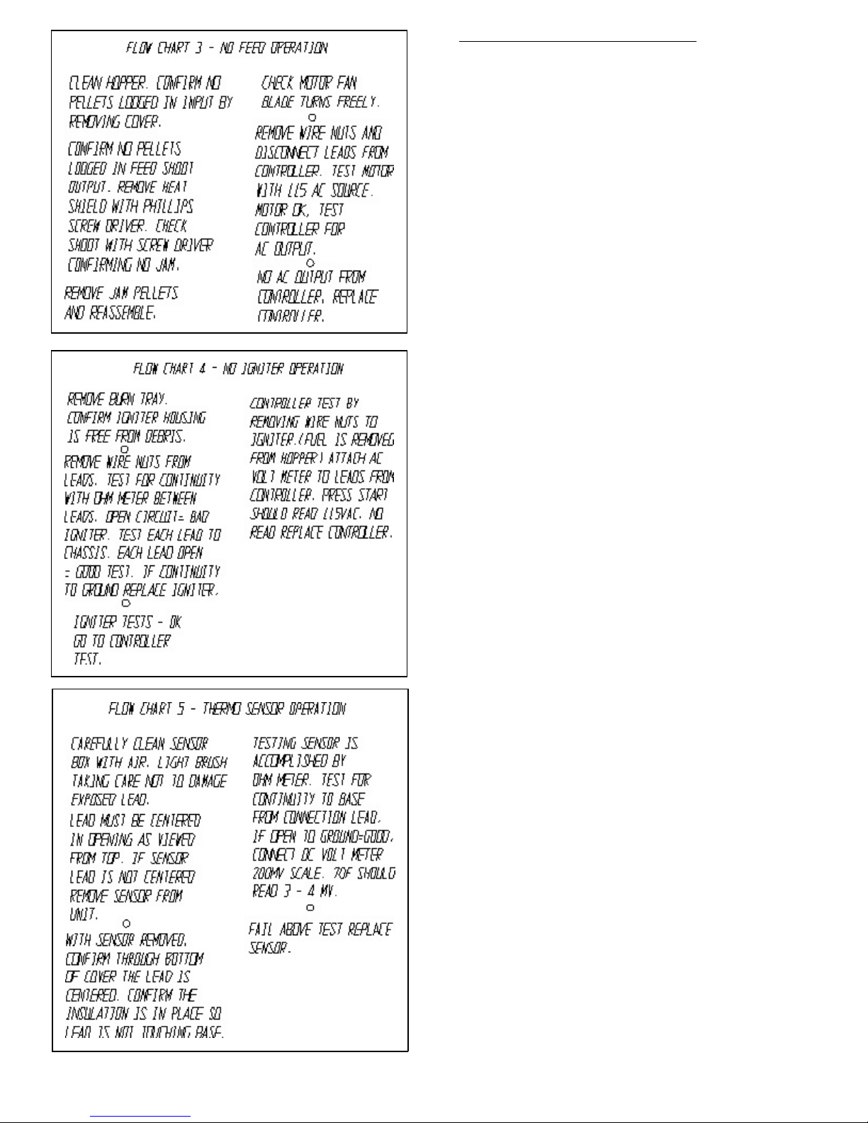
TES T ING & SE R VIC ING T H ERM O -SENSOR
The therm o-sensor is loc ate d on the le ft s ide in te rior of
the chassis. It is protected by a steel hood and is
designe d for s ta nda rd grill operations . The sensor does
not require reg ular se rvic e e xcept to confirm it is free
from cook in g debris.
It m ay be poss ible however to dam age the se nsor if
som e item is pushed through the hood acc ess or is hit
hard enoug h to dis place the lead e nd. T e stin g of ths
senso r is the refore as im portant as the m ain control test.
Outline of the basic control test will provide gene ral
operation of the sensor an d fee d back to the c ontro ller. If
the sensor o peratio n w arran ts furthe r eva lu atio n
com p le te the following tests:
1) Check sensor physical d am age or d ebris in ho od or
hood ve nt hole.
* Clean with a ir or soft b rus hing action to rem o ve
build u p. Care sho u ld be taken not to bend or
da m a ge le ad end.
Therm o -Se nsor - L o cated le ft inside bas e
2) Check sensor lea d attac hm e nt to th e controlle r by
accessing m ain co ntrol th rough front pan el.
* Confirm the screw s that hold the leads are tight.
Care sho u ld be taken no t to over tig hte n a s the
ba se is m ad e o f plastic .
* Loose attachm en t cou ld c ause e rratic s enso r reads
by con troller.
* Leads have sp ecific polarity and m us t be attache d to
the prope r lug. R efer to the colo rs no te d on th e
board base, RED & YELLO W .
* Reversing the polarity will cause the grill to read a
reducing te m pe rature when the a ctual tem pe rature is
increasing. T he ope rating result is to start the g rill
and a run o f less than 5 m in utes with a C o L shut
down.
3) Se nsor G rounding to Chassis cau sing con trol
function problem s and m issed s tarts.
* The s enso r leads sh ould not come in c ontact with
the chassis to a c ause a ground con dition . This will
cause the co ntroller to act erratic.
* Starts tha t continu e beyond the 32 5° target w ithout
run m o de initiation and e rratic sh ut downs leading to
fast C o L cycles are direc tly caus ed by grounde d
sensors.
* Testing for g rou nding requires th e sens or lead s to be
disconnected from the c ontrolle r and a O HM m e ter
applied to c hass is a nd one s ensor lead. If c ontinuity
is fo und the se nsor is groun ded an d shou ld b e
rem oved for insp ection and possible replacem e nt.
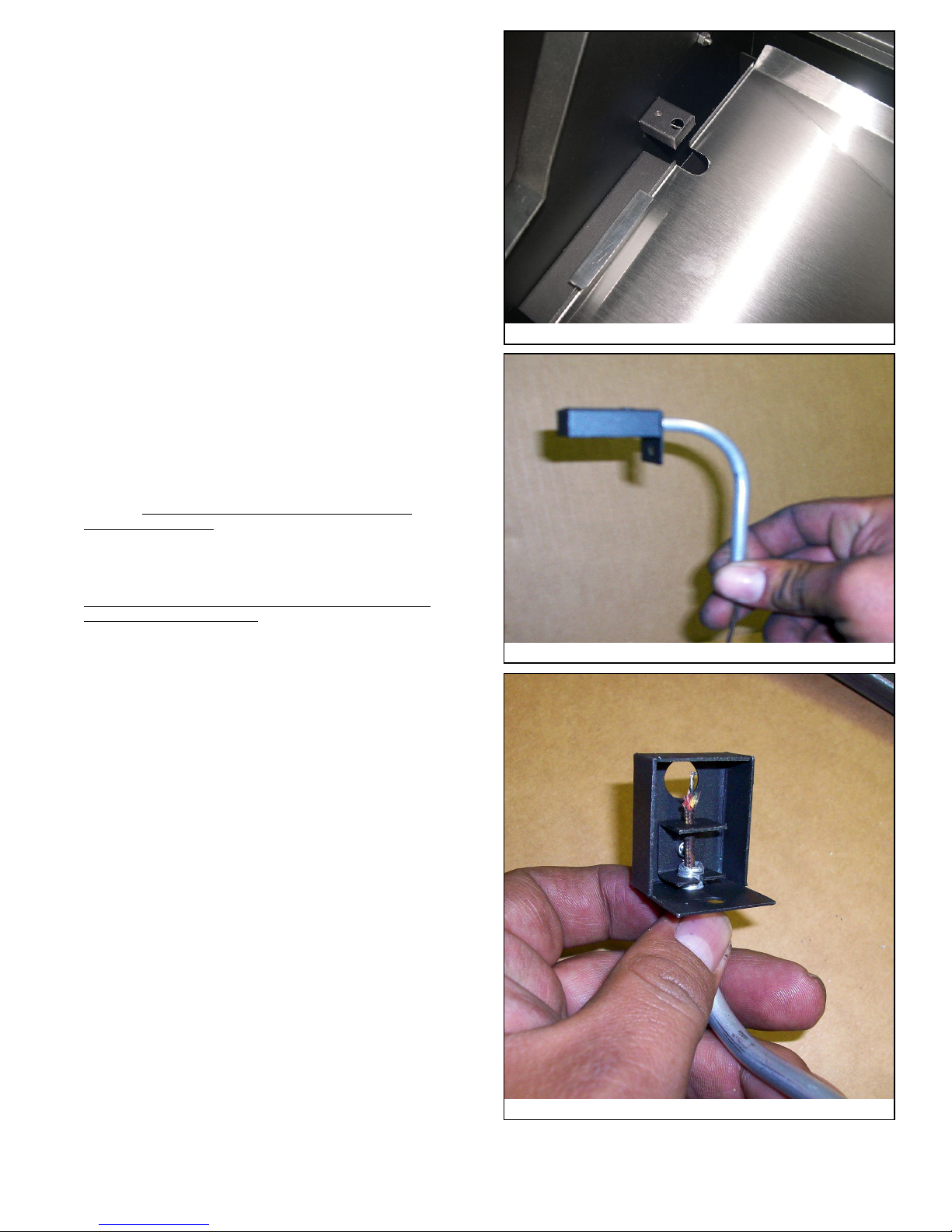
Therm o-sensor Assem bly
TES T ING & SE R VIC E AUG ER, FAN , AN D IGNIT E R
Tes t proce dures for th ese co m ponen ts a re sign ificantly
the sam e as they are basic 115VAC lo ads . Eac h
com p onent can be re m oved for electric testing an d or
tested in place. The following is an ite m spe cific
description :
Therm o-sensor lead p lacement
-3 -
 Loading...