

Sweepster QC 210 Series Manual

51-3880, 11/08 1
QC Series
210 Series
Hydraulic Windrow Sweepers
for Skid Loaders
Sweepster Serial Number____________________ Manual Number: 51-3880
Release Date: November 3, 2008
Serial Number 0733001 and Up
800-456-7100 www.paladinlcg.com Sweepster 2800 N. Zeeb Rd., Dexter, MI 48130 United States of America

2 51-3880, 11/08

51-3880, 11/08 3
Table of Contents
Section 1 ... Installation.................................................... 5-13
Section 2 ... Operation and Maintenance ..................... 15-23
Section 3 ... Service ........................................................ 25-30
Section 4 ... Parts............................................................ 31-43
Section 5 ... Options ....................................................... 45-54
Section 6 ... Appendix .................................................... 54-61

4 51-3880, 11/08

51-3880, 11/08 5
Installation Manual
QC Series Angle Brooms
Table of Contents
Introduction ...............................................................6
Safety Information ................................................7-13
General Safety Information .................................... 7-8
Safety Signs & Labels ........................................ 10-11
Product Information Section ....................................12
Installation/Storage ................................................. 13

6 51-3880, 11/08
SAFETY SECTION
INTRODUCTION
Introduction
Importance of this Manual
Read this manual before attempting to operate
the equipment.
This operator’s manual should be regarded as part of the
sweeper. Suppliers of both new and secondhand sweepers are
advised to keep documentation indicating that this manual was
provided with the sweeper.
The manual contains information regarding installation,
operation and maintenance required for this sweeper and
optional equipment. It also includes detailed parts lists.
Purpose of Sweeper
This sweeper is designed solely for use in construction cleanup,
road maintenance, grounds maintenance and similar
operations. Use in any other way is considered contrary to the
intended use. Compliance with and strict adherence to
operation, service and repair conditions, as specied by the
manufacturer, are also essential elements of the intended use.
Contacting SWEEPSTER
If you have any questions about information in this manual or
need to order parts, please call, write, fax or e-mail
SWEEPSTER.
SWEEPSTER
2800 North Zeeb Road
Dexter, Michigan 48130
Phone: (734) 996-9116 - (800) 456-7100
FAX: (734) 996-9014
e-mail: sweepster@paladinbrands.com
For help with installation, operation or maintenance
procedures, contact our Technical Service Department. Direct
product questions and parts orders to our Sales Department.
When ordering parts or accessories, be prepared to give the
following information:
•Sweeper model, serial number and date of
purchase
•Prime mover, make and model
•Part number, description and quantity
This sweeper should be operated, serviced and repaired only
by persons who are familiar with its characteristics and
acquainted with relevant safety procedures.
Accident prevention regulations, all other generally
recognized safety regulations and all road trafc regulations
must be observed at all times.
Any modications made to this sweeper may relieve the
manufacturer of liability for any resulting damage or injury.
Safety Alert Symbol
This safety alert symbol indicates important safety
messages in this manual. When you see this symbol, be
alert to the possibility of injury. Carefully read the message that
follows and inform other operators.
Terms Used in Manual
Right-hand, left-hand, front and rear are determined from the
operator’s perspective (either the operator’s seat or standing
behind a walk-behind unit), facing forward in the normal
operating position.
Prime mover refers to the tractor, truck, loader or tow vehicle
that the sweeper is mounted on or towed by.
Optional Equipment
Installation instructions for optional equipment, if applicable,
appear in the Service Manual Section.
Specications & Features
Due to continuous product improvement, specications and
features may change without notice.
Warranty
To validate the warranty for this unit, ll out the warranty card or
warranty pages located at the back of this manual. Then, send
this information to SWEEPSTER.

51-3880, 11/08 7
SAFETY SECTION
GENERAL SAFETY INFORMATION
Safety Information
Read this manual
Read all safety information in this manual. All
operators must read and understand the entire
contents of this manual before sweeping.
General safety practices are listed on Safety
Information pages and specic safety
information is located throughout this manual.
Hazard Denitions
Four hazard classications are used in this manual. They are
DANGER - Indicates an imminently hazardous
situation which, if not avoided, will result
in death or serious injury.
WARNING
situation which, if not avoided, could
result in death or serious injury.
CAUTION - Indicates a potentially hazardous
situation which, if not avoided, may result
in minor or moderate injury.
NOTICE - Used for instructions when machine damage
may be involved.
Operation
CAUTION
Only fully trained operators or trainee
operators under the close supervision of
a fully trained person should use this
machine.
Before operating sweeper:
•Learn sweeper and prime mover controls in an off-road
location.
•Be sure that you are in a safe area, away from trafc or
other hazards.
•Check all hardware holding the sweeper to the prime
mover, making sure it is tight.
•Replace any damaged or fatigued hardware with
properly rated fasteners. See Maintenance Section
- Indicates a potentially hazardous
- A sweeper is a demanding machine.
•Check prime mover tire pressure before sweeping.
•Check tire ratings to be sure they match the prime
mover load. Weigh the sweeper end of the prime
mover, if necessary, to insure proper tire rating.
•Remove from the sweeping area all property that
could be damaged by ying debris.
•Be sure all persons not operating the sweeper are
clear of the sweeper discharge area.
• Always wear proper apparel such as a long-sleeved
shirt buttoned at the cuffs; safety glasses, goggles
or a face shield; ear protection; and a dust mask.
While operating sweeper:
•When operating sweeper, adhere to all government
rules, local laws and other professional guidelines for
your sweeping application.
WARNING - Never raise the sweeper more than a few
feet off the ground. The sweeper can tip
back or the prime mover can tip over
causing death or serious injury,
• Before leaving the operator’s area for any reason, lower
the sweeper to the ground. Stop the prime mover
engine, set the parking brake and remove the key from
the ignition.
• Minimize ying debris - use the slowest rotating speed
that will do the job. See Operation Section: Operating
Tips
• Keep hands, feet, hair and loose clothing away from all
moving parts.
• Leave the brush hood (shield) and all other shields and
safety equipment in place when operating the sweeper
and prime mover.
• Be aware of the extra weight and width a sweeper adds.
Reduce travel speed accordingly. See Product
Information Section: Operating the Sweeper.
• When sweeping on rough terrain, reduce speed to avoid
“bouncing” the sweeper. Loss of steering can result.
• Never sweep toward people, buildings, vehicles or other
objects that can be damaged by ying debris.
• Only operate the sweeper while you are in the operating
position. The safety restraint must be fastened while
you operate the prime mover. Only operate the controls
while the engine is running. Protective glasses must be
worn while you operate the prime mover and while you
operate the sweeper.
•Make sure all hydraulic hardware and hydraulic ttings
are tight.
•Replace any damaged or fatigued ttings or hoses.
• While you operate the sweeper slowly in an open area,
check for proper operation of all controls and all
protective devices. Note any needed repairs during
operation of the sweeper. Report any needed repairs.

8 51-3880, 11/08
SAFETY SECTION
GENERAL SAFETY INFORMATION
Service & Repair - General
CAUTION - Do not modify the sweeper in any way.
Personal injury could result. If you have
questions, contact your dealer or
SWEEPSTER.
Repair or adjust the sweeper in a safe area, away from
trafc and other hazards.
Before adjusting or servicing - lower the sweeper to the
ground, set parking brake, shut down the prime mover
and remove the key from the ignition.
When working on or around the sweeper, safely secure it
from falling or shifting.
Service & Repair - Hydraulic Safety
Stop the prime mover engine and release hydraulic pressure
before servicing or adjusting sweeper hydraulic systems.
WARNING - Escaping hydraulic uid can have
enough pressure to penetrate the skin,
causing serious personal injury.
Check lines, tubes and hoses carefully. Do not use your
hand to check for leaks. Use a board or cardboard to check
for leaks. Tighten all connections to the recommended
torque. See Appendix.
Do not bend high pressure lines. Do not strike high pressure
lines, Do not install bent lines, bent tubes, or kinked hoses.
Do not install damaged lines, damaged tubes, or damaged
hoses.
Repair loose lines, loose tubes, and loose hoses. Repair
damaged lines, damaged tubes, and damaged hoses.
Leaks can cause res. See your SWEEPSTER dealer
for repair or replacement parts.
Replace the parts if any of the following conditions are
present:
•The end ttings are damaged or leaking.
•The outer covering is chafed or cut.
•The reinforcing wire layer is exposed.
•The outer covering is ballooning locally.
•The hose is kinked or crushed.
•The hoses have been pulled or stretched.
Make sure that all clamps, guards, and shields are installed
correctly.

51-3880, 11/08 9
Notes
10 51-3880, 11/08
7
5
6
4
2
4
3
7
SAFETY SECTION
SAFETY SIGNS & LABELS
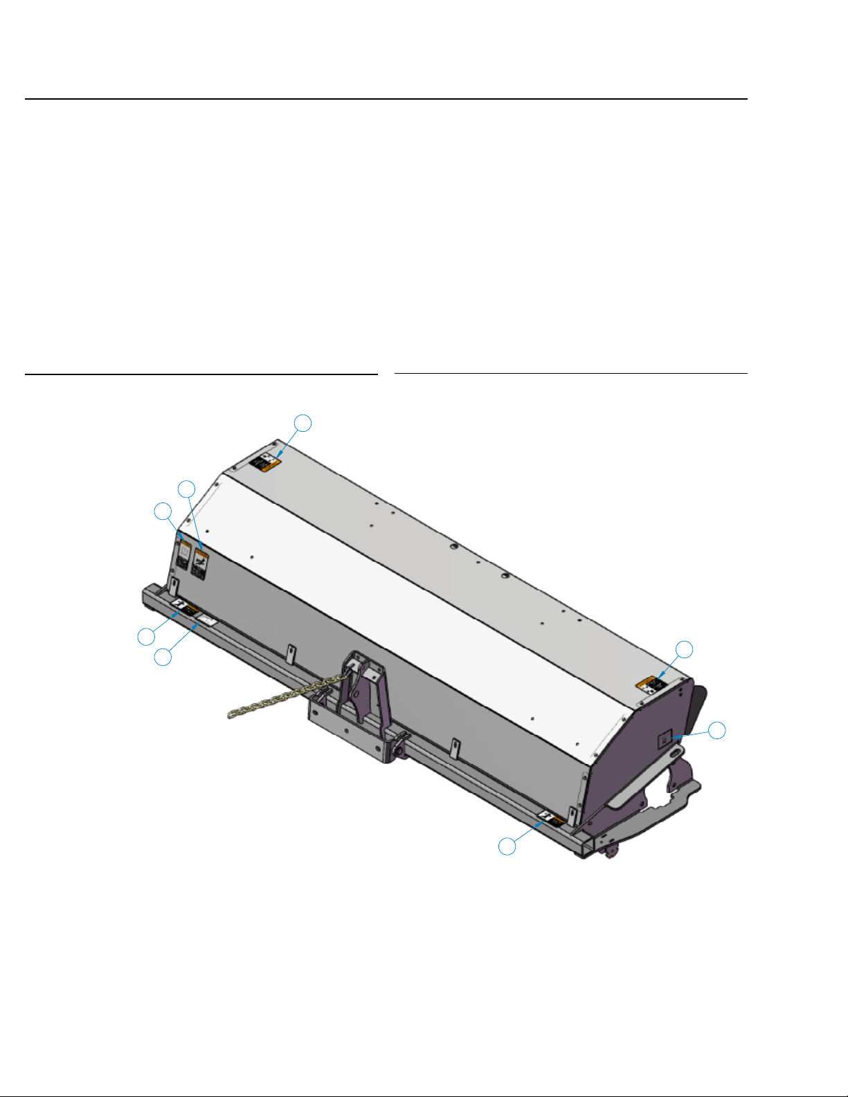
Safety Signs and Labels
There are several specic safety signs on this sweeper. The
exact location of the hazards and the description of the
hazards are reviewed in this section.
Placement or Replacement of Safety Signs
1. Clean the area of application with nonammable solvent,
and then wash the same area with soap and water.
2. Allow the surface to fully dry.
3. Remove the backing from the safety sign, exposing the
adhesive surface.
4. Apply the safety sign to the position shown in the diagram
above and smooth out any bubbles.
Instructions
• Keep all safety signs clean and legible.
• Replace all missing, illegible, or damaged safety signs.
• Replacement parts, for parts with safety signs attached,
must also have safety signs attached.
• Safety signs are available, free of charge, from your dealer
or from SWEEPSTER.
Item Part Qty Description
2. 50-0634 1 Label, Serial Number
3. 50-0643 2 Label, Tie Down Point
4. 50-0721 2 Label, Warning, Crush Hazard
5. 50-0722 1 Label, Warning, Misuse Hazard
6. 50-0724 1 Label, Warning, High Pressure Fluid Hazard
7. 50-0726 2 Label, Warning, Flying Objects & Entanglement

51-3880, 11/08 11
SAFETY SECTION
SAFETY SIGNS AND LABELS
Safety Signs and Labels
2. 50-0634
3. 50-0643
4. 50-0721
6. 50-0724
5. 50-0722
7. 50-0726

12 51-3880, 11/08
OPERATION SECTION
PRODUCT SPECIFICATIONS
Product Information
Section
Specications and Model
Views
Maximum Width at 0° Articulation
Maximum Width at Full Articulation
Approximate Weight
with SAE J2513
Mounting
Maximum Length at 0°
Articulation
Maximum Width at 0°
Articulation
Maximum Length at 0° Articulation
Maximum Length at
Full Articulation
Maximum Width at
Full Articulation
Sweeping Width at 0º
Articulation
Sweeping Width at Full
Articulation
QC Brush Head
Single Motor Dual Motor
793 lbs 829 lbs 5 Ft
852 lbs 890 lbs 6 Ft
915 lbs 953 lbs
982 lbs
71 inches with SAE J2513
Mounting
70.5 inches 5 Ft
82.5 inches 6 Ft
94.5 inches
106.5 inches 8 Ft
79.5 inches 5 Ft
82.5 inches 6 Ft
85.5 inches 7 Ft
88.5 inches 8 Ft
72 inches 5 Ft
82 inches 6 Ft
93 inches
103 inches 8 Ft
60 inches 5 Ft
72 inches 6 Ft
84 inches 7 Ft
96 inches
54 inches 5 Ft
64 inches 6 Ft
75 inches 7 Ft
85 inches 8 Ft
7 Ft
1022 lbs 8 Ft
7 Ft
7 Ft
8 Ft
Maximum Length at Full Articulation

51-3880, 11/08 13
INSTALLATION SECTION
INSTALLING/REMOVING SWEEPER & STORAGE
Sweeper Installation
(Broom to Prime Mover)
WARNING - Improper attachment of sweeper could
result in injury or death. Do not operate
this machine until you have positive
indication that the attachment is securely
mounted.
1. Position the broom on a level surface.
2. Enter the prime mover.
3. Fasten the safety restraints.
4. Start the engine.
5. Disengage the parking brake.
6. Align the attachment mechanism with the mounting on the
broom, attach to the prime mover. Follow the attaching
procedure in the prime mover owners manual.
7. Engage the parking brake and shut down the prime
mover. Be sure to relieve pressure to the auxiliary
hydraulic lines.
8. Unfasten safety restraints and exit the prime mover.
Removing the Sweeper
WARNING - Serious injury or death may result from
disengaging the sweeper when the
sweeper is in an unstable position or
carrying a load. Place the sweeper in a
stable position before disengaging.
NOTICE - Hoses for the sweepers must be removed before
the quick attach is disengaged. Pulling the
sweeper with the hoses could result in damage
to the prime mover or the sweeper.
1. Lower the broom to the ground.
2. Engage the parking brake and shut down the prime
mover. Be sure to relieve pressure to the auxiliary
hydraulic lines.
3. Unfasten safety restraints and exit prime mover.
4. Lock jack stands in lowered position. (if available)
5. Disconnect the broom hydraulic lines from the prime
mover. Connect quick couplers together to keep clean.
6. Disengage attachment locking mechanism.
(mechanical type)
9. Lock jack stands in stowed position. (if available)
10. Ensure that the hydraulic quick couplers are clean.
Connect hydraulic lines for the broom to the
prime mover. Twist the collar of the quick couplers
one quarter of a turn in order to secure the hydraulic
connections.
11. While the loader arms are lowered, visually inspect the
attachment mechanism to ensure that it is securely
mounted.
12. Enter prime mover, fasten safety restraints and start the
prime mover.
13. Carefully raise the loader and cycle the rollback/dump
cylinders to check clearances, that limiting stops make
proper contact and verify that all mounting procedures
have been successfully completed. Contact SWEEPSTER
for instructions if the limiting stops do not contact properly.
7. Enter prime mover, fasten safety restraints and start the
prime mover.
8. Disengage attachment mechanism. (hydraulic type)
9. Disengage the parking brake, and back away from the
broom.
Storage
NOTICE - Do not store the sweeper with weight on the
brush. Weight will deform the bristles,
destroying the sweeping effectiveness. To
avoid this problem, place the sweeper on
blocks or use storage stands.
Do not store polypropylene brushes in direct
sunlight. The material can deteriorate and
crumble before the bristles are worn out.
Keep polypropylene brush material away from
intense heat or ame.

14 51-3880, 11/08
Notes

51-3880, 11/08 15
Operation and
Maintenance Manual
QC Series Angle Brooms
Table of Contents
Operation .............................................................16-18
Operation ........................................................................16
Leveling Sweeper ........................................................17-18
Maintenance. .......................................................19-23
Brush Pattern Adjustment .................................................19
Maintenance Schedule .....................................................20
Maintenance Record .........................................................21
Replacing Brush Sections .................................................22
Lubrication Points ............................................................ 23

16 51-3880, 11/08
OPERATION SECTION
SWEEPING/OPERATING TIPS
Before Each Use
Perform daily maintenance as indicated in Maintenance
Schedule.
Run the prime mover and sweeper at a slow idle. Check for
hydraulic leaks or other problems and make corrections, if
necessary, before using the sweeper. See “Hydraulic
inspection guideline” .
WARNING - Avoid serious injury. Check for large
objects that could harm the operator or
others if thrown by the sweeper. Remove
these items before operating.
During Use
Directing Debris
Carry the sweeper low to the ground so that the operator has
good visibility and stability. Avoid any sudden movements.
Avoid excessive downward pressure on the brush sections to
prevent
excessive wear. A two to four inch wide pattern is sufcient for
most
applications. Ensure that the adjustment bolts are equally
adjusted in order to prevent an uneven wear pattern. To adjust
brush pattern see “Adjusting Brush Pattern”.
Direct debris by angling the brush head in that direction.
Observe wind direction. Sweeping with the wind makes
sweeping more effective and helps keep debris off the
operator.
The terms swing and angle are used interchangeably.
4. Engage the brush and then lower it to the ground.
5. Increase prime mover engine rpm to sweeping speed.
6. Travel forward at 5 mph (8 kph) or less.
NOTICE - Avoid sweeper damage. Reduce travel speed to
avoid hitting immovable objects.
Operating Tips
NOTICE- Avoid sweeper damage. Do not ram into piles.
Use an appropriate attachment for this type
of job.
Brush, Engine & Travel Speeds
Vary brush, engine and travel speeds to match sweeping
conditions.
Large Areas
When sweeping a large area, such as a parking lot, make a
path down the middle and sweep to both sides. This reduces the
amount of debris that the sweeper must sweep to one side.
Snow
Fast brush speeds and slow travel speeds are needed to sweep
snow effectively. Start at 3/4 throttle and the lowest gear of the
prime mover. For wet and/or deep snow, increase to almost full
throttle. This helps keep snow from packing up inside the brush
hood.
In deep snow you may need to make multiple passes to get
down to a clean surface.
Manual Angle
1. Remove the quick release pin from the swing plate.
2. Position the brush head at the desired angle, aligning
holes in the swing plate and mounting frame.
3. Re-insert the quick release pin.
Hydraulic Angle
1. Start the prime mover.
2. Position the brush head at the desired angle by using
Sweeping
To sweep:
1. Manual angle only - Swing the brush head assembly
the direction that you want to direct debris.
2. Start the prime mover at idle and raise the brush.
3. Hydraulic angle only - Swing the brush head assembly
the direction that you want to direct debris.
To keep snow from blowing back onto a swept area, always
sweep so the wind is at your back.
Dirt & Gravel
To keep dust at a minimum, use the optional dust suppression
kit or plan sweeping for days when it is overcast and humid or
after it has rained. Also, sweep so the wind blows at your back.
Low brush speeds and moderate travel speeds work best for
cleaning debris from hard surfaces. Brush speeds that are too
fast tend to raise dust because of the aggressive sweeper
action.
To sweep gravel, use just enough brush speed to “roll” the
gravel, not throw it.
Heavy Debris
Travel slowly - 2-3 mph. (3-5 kph)
Sweep a path less than the full width of the sweeper.
Increase engine speed if debris becomes very heavy.
51-3880, 11/08 17
MAINTENANCE SECTION
LEVELING THE SWEEPER
Leveling
Level the sweeper for even brush wear and effective use.
CAUTION - Avoid injury. Before adjusting the sweeper,
always turn off the sweeper and the prime
mover engine and remove the key.
1. Move the sweeper to a at, paved surface.
2. Lower the brush head assembly so the brush is 2 inches
(51 mm) above the ground.
3. Engage the parking brake and shut down the prime
mover. Be sure to relieve pressure to the auxiliary
hydraulic lines.
4. Unfasten safety restraints and exit prime mover.
5. Check if the swing assembly is level by using a bubble
level. To make corrections:
Adjust tilt cylinders. If the front of the swing assembly is
high, extend tilt cylinders. If low, retract cylinders.
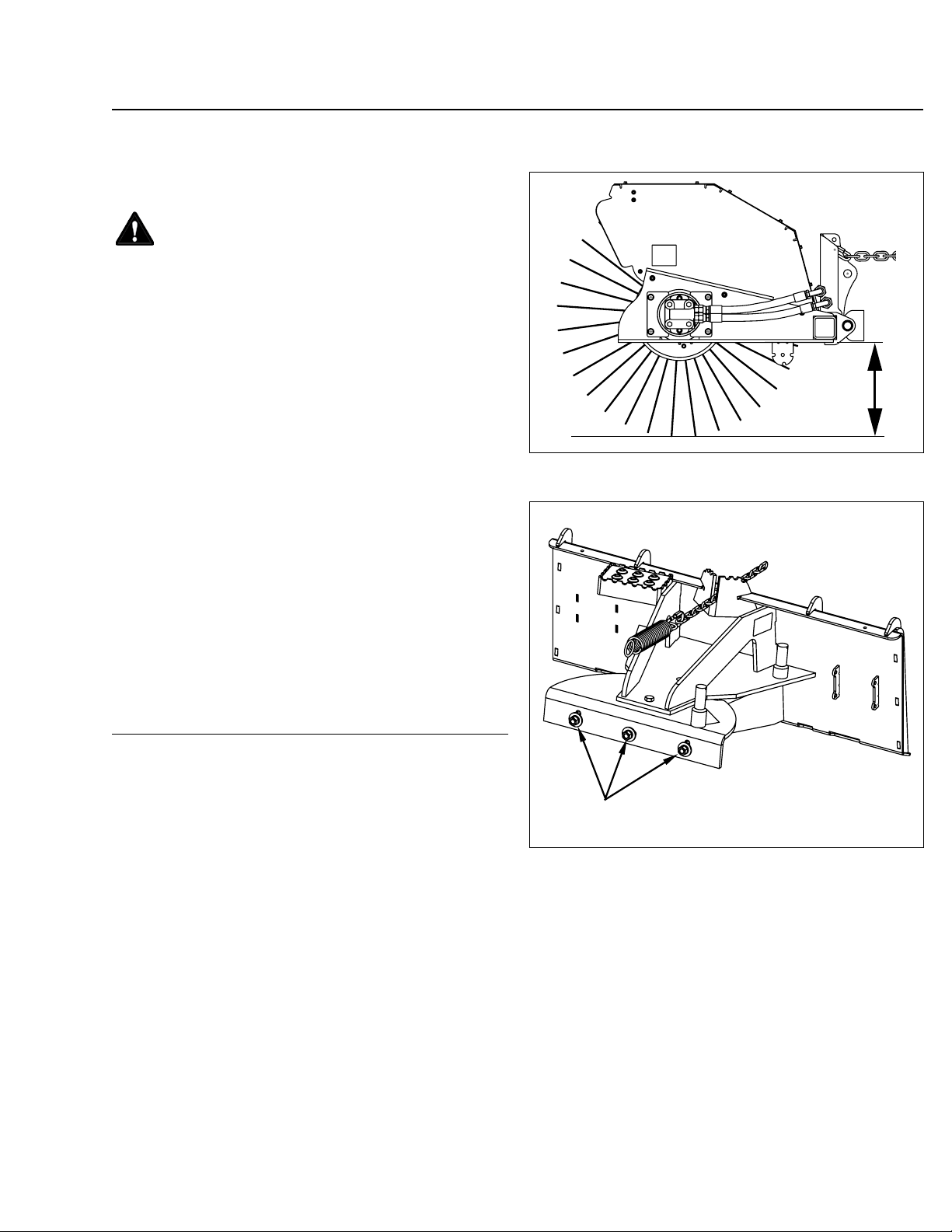
6. Position the brush head assembly straight ahead. On
each side, measure from the brush frame to the ground
(gure 1). If measurements are not equal:
Loosen hardware that attaches the swing assembly to
the brush head assembly; lower the high side of the
brush head until both sides are an equal distance above
the ground. Tighten the hardware. (gure 2)
gure 1
gure 2
18 51-3880, 11/08
MAINTENANCE SECTION
LEVELING THE SWEEPER
Low
gure 3
High
gure 4
High
Low
High
Low
Low
High
High
gure 5
Low
gure 6
Low
High
High
Low
Low
High
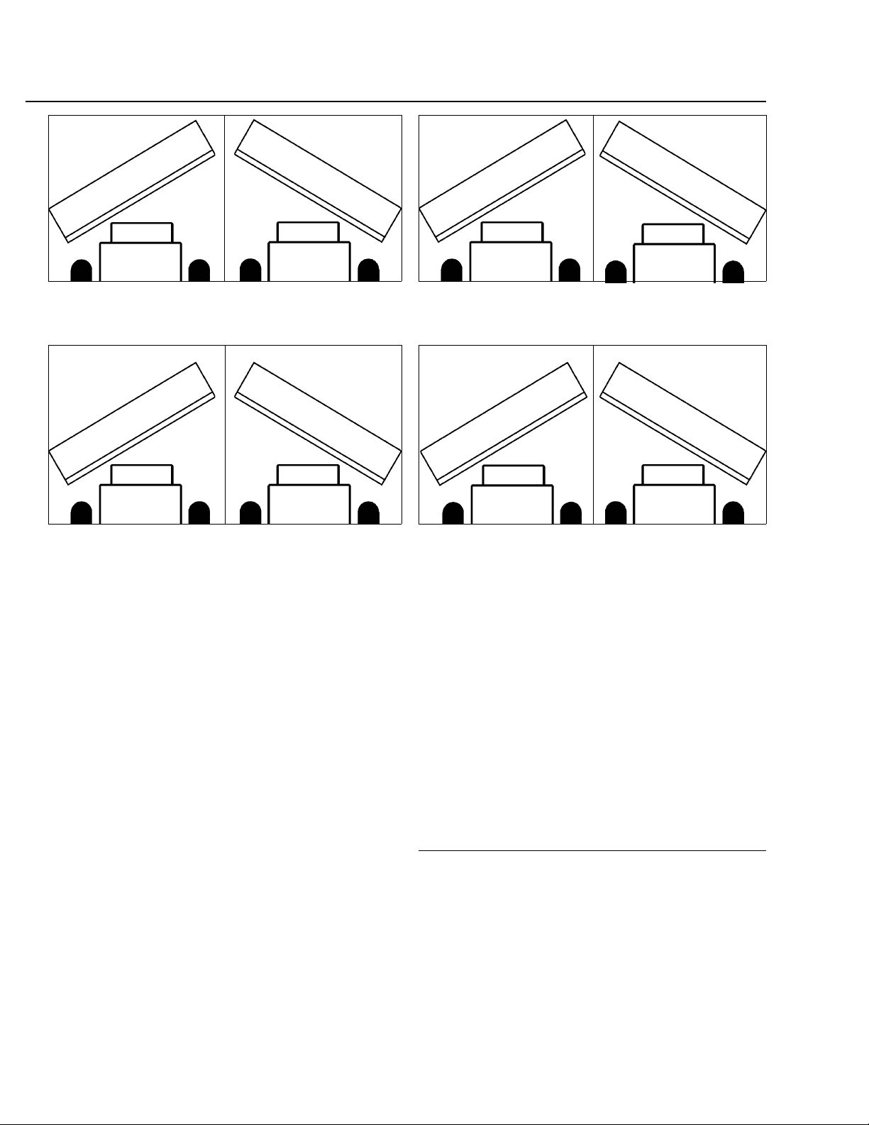
7. Measure to see if the brush head assembly is level when
angled. First, angle the brush head to the right. Measure
as in step 4. Then, angle the brush head to the left.
Measure again. If measurements are equal, the
sweeper is level. If not, proceed with this step.
To correct leveling problems shown in:
• gure 3, extend tilt cylinders.
• gure 4, retract tilt cylinders.
• gure 5, loosen hardware that attaches the swing
assembly to the brush head assembly; lower the
left-hand side of the brush head until both sides are an
equal distance above the ground. Tighten the
hardware.
• gure 6, loosen hardware that attaches the swing
assembly to the brush head assembly; lower the right hand side of the brush head until both sides are an
equal distance above the ground. Tighten the
hardware.
51-3880, 11/08 19
MAINTENANCE SECTION
BRUSH PATTERN/SPRING CHAIN/TRANSPORT CHAIN
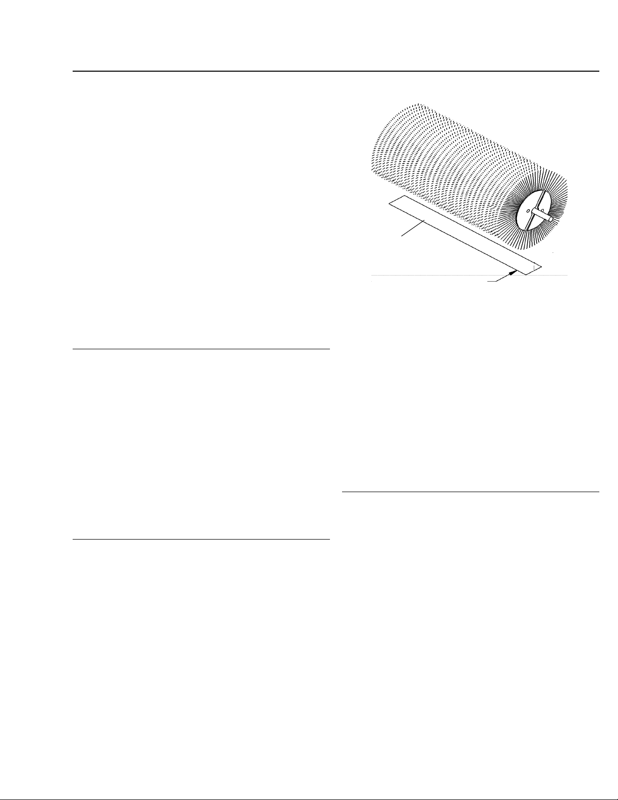
Setting Brush Pattern
A properly adjusted brush offers the best sweeper
performance. To check the brush pattern:
1. Move the sweeper to a dusty, at surface.
2. Set the prime mover’s parking brake and leave the engine
running.
3. Start the sweeper at a slow speed: lower it so the bristle
tips touch the ground. Run the sweeper in a stationary
position for 10 seconds.
Swept Area
4. Raise the sweeper and back away; switch off the engine
and remove the key. The brush pattern left in the dust
should be 2-4 inches (51-102 mm) wide, running the
length of the brush. (Compare the swept area with
gure 7.)
2-4 in.
(51-102 mm)
5. Adjust the brush pattern as necessary according to
instructions found in adjusting the Spring-Chain
Assembly.
Adjusting Spring-Chain Assembly
The spring-chain assembly allows the brush head to pivot up
and down.
To adjust the brush pattern:
1. Lower the sweeper.
2. Tighten the transport chain and lower the sweeper so the
transport chain supports weight.
3. Move the spring chain forward in the swing assembly
chain holder to lower the brush head or backward in the
holder to raise it.
Figure 7
Tightening Transport Chain
The transport chain supports the weight of the brush head
assembly during transport between work sites and during
adjustment of the spring-chain assemblies.
To adjust the transport chain:
1. Extend tilt cylinders.
2. Tighten the transport chain.
3. Retract tilt cylinders.
 Loading...