

Page 1
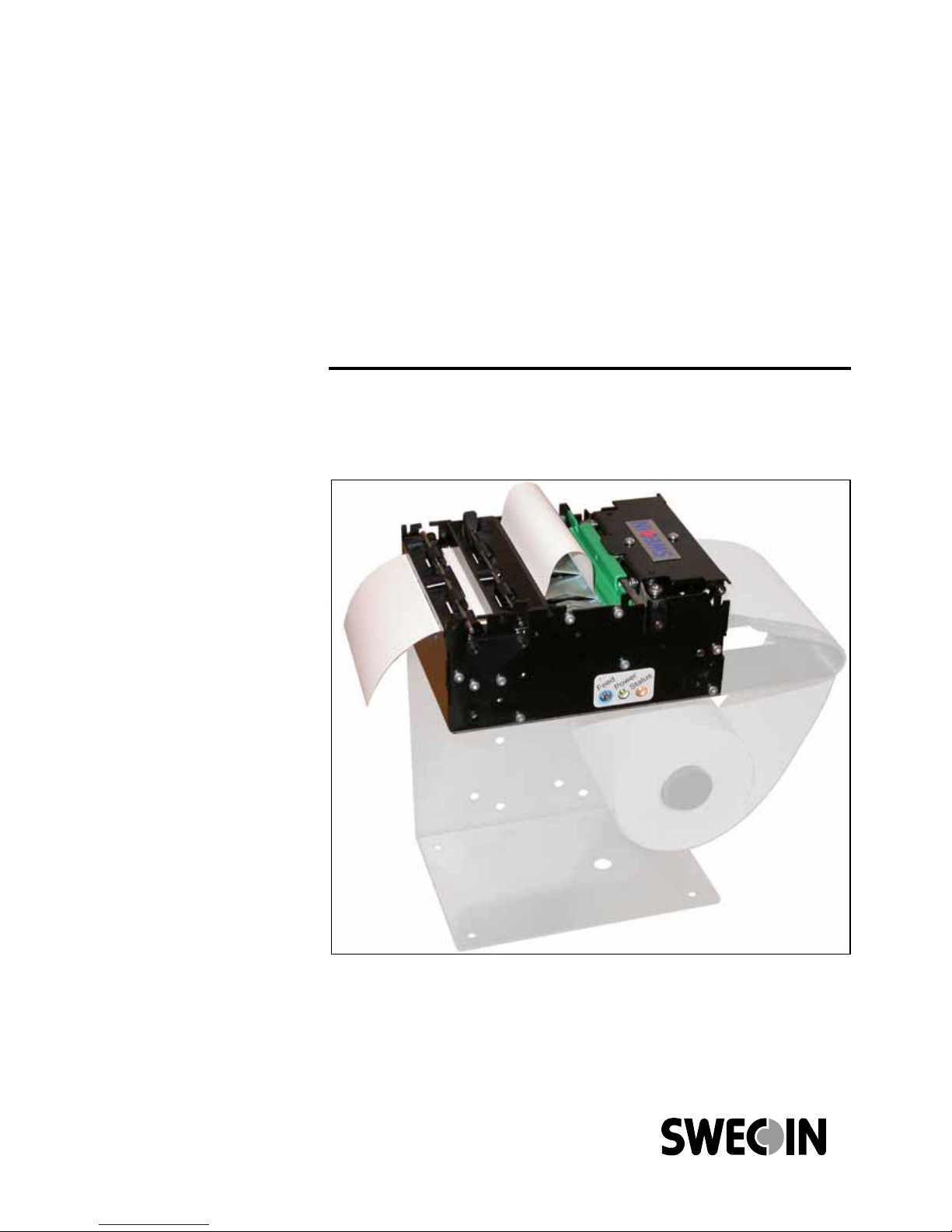
Swecoin Kiosk Printer
TTP 2000 Model
Technical Manual
94822
Page 2
Publ. No.: 103471, Ed. D, February 20, 2006
TTP 2000 Kiosk Printer
Technical Manual
Page 3

2
Acknowledgments
Adobe and Acrobat are trademarks of Adobe Systems
Incorporated
Windows is a trademark of Microsoft Corporation
This is a publication of Swecoin AB
Box 322, SE-192 30 SOLLENTUNA, Sweden
Phone +46 8 623 45 60
Fax +46 8 594 709 89
E-mail [email protected]
Web site http://www.swecoin.se
© Swecoin AB 2004, 2005
All rights reserved. Reproduction in whole or in parts is prohibited without written consent of the copyright
owner. We have taken great care to ensure that the information in this manual is correct and complete.
However, if you discover any errors or omissions, or if you wish to make suggestions for improvements, you
are welcome to send your comments to us. Swecoin AB disclaims any liability resulting from the use of this
information and reserves the right to make changes without notice.
Edition D, February 2006
Printed in Sweden
Page 4

Introduction
0602 TTP 2000 Kiosk Printer–Technical Manual 3
CONTENTS
1 Introduction...................................................................................................................5
1.1 About this manual............................................................................................5
1.2 Updating ..........................................................................................................5
2 Product presentation....................................................................................................6
2.2 Controls ...........................................................................................................8
3 Installation...................................................................................................................10
3.1 Installing a paper guide .................................................................................10
3.2 Installation considerations.............................................................................11
3.3 Installing a paper-low sensor (option) ...........................................................15
3.4 Connecting to the computer ..........................................................................16
3.5 Connecting the power ...................................................................................18
3.6 Making a test printout ....................................................................................19
3.7 Installing a printer driver................................................................................20
4 Operation.....................................................................................................................22
4.1 Installing a paper roll .....................................................................................22
4.2 Clearing paper jams ......................................................................................24
5 Programming ..............................................................................................................25
5.1 How the commands are described................................................................26
5.2 Summary of control codes & escape sequences..........................................27
5.3 Software command syntax............................................................................29
5.4 Font loading...................................................................................................54
5.5 Logotypes......................................................................................................56
5.6 Status reporting .............................................................................................58
6 Default parameter settings ........................................................................................59
6.1 How the parameters are described ...............................................................59
6.2 Summary of parameter settings ....................................................................60
6.3 Serial interface set-up ...................................................................................61
6.4 Parallel port setup .........................................................................................62
6.5 Print setup .....................................................................................................62
7 Page setup...................................................................................................................69
7.1 Printable area ................................................................................................69
7.2 Aligning preprint and thermal print ................................................................70
7.3 Parameters used ...........................................................................................71
7.4 Black-mark sensing from within "Windows" ..................................................74
Page 5

Introduction
4 TTP 2000 Kiosk Printer–Technical Manual 0602
8 Interface.......................................................................................................................75
8.1 Serial, TTP 2010 ...........................................................................................75
8.2 Parallel, TTP 2020.........................................................................................76
8.3 USB, TTP 2030 .............................................................................................77
9 Maintenance................................................................................................................78
9.1 Fault finding...................................................................................................78
9.2 Cleaning the print head .................................................................................79
9.3 Firmware........................................................................................................79
10 Specifications .............................................................................................................86
10.1 General..........................................................................................................86
10.2 Paper.............................................................................................................86
10.3 Text Mode .....................................................................................................87
10.4 Miscellaneous................................................................................................88
10.5 Life Expectancy .............................................................................................88
10.6 Ordering number list......................................................................................89
10.7 Dimensions....................................................................................................90
REGISTER NOW!
If you wish to stay informed of product changes, manual updates etc., you are
welcome to subscribe to our bulletin service.
To register as a subscriber, either visit our web site http://www.swecoin.se to fill in
your subscription request, or send e-mail to [email protected].
Enter the text Subscribe bulletins as the subject. Do not enter any text in the message
area.
Registration date (for your own records):
REVISION HISTORY
Edition A: This issue, describes TTP 2000 with firmware version 2.52
Edition B: This issue, describes TTP 2000 with firmware version 3.05+
Edition C: This issue, describes TTP 2000 with firmware version 3.10
Edition D: This issue, describes TTP 2000 with firmware version 3.20
Page 6

Introduction
0602 TTP 2000 Kiosk Printer–Technical Manual 5
1 INTRODUCTION
1.1 About this manual
1.2 Updating
This manual will be updated as, from time to time, printer functions and features may be
added or amended. You will always find the latest edition on our web site
(http://www.swecoin.se). You can order printed copies of the current manual by e-mail,
fax, or phone.
If you require functions not found in the manual edition at your disposal, you are welcome
to consult one of our representatives for information.
Page 7
Product presentation
6 TTP 2000 Kiosk Printer–Technical Manual 0602
2 PRODUCT PRESENTATION
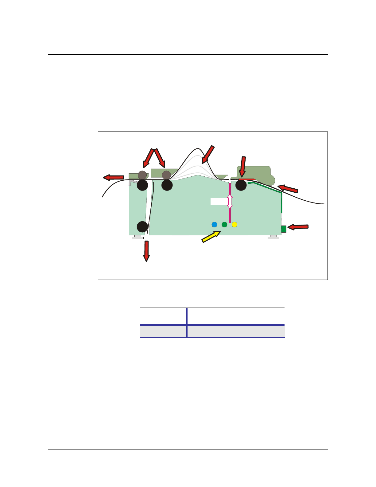
The TTP 2000 series are kiosk printers for 58 to 82.5 mm paper using direct thermal
printing. It has integrated guillotine cutter, looping presenter with built in retract and retain
function, and control board. The print speed is 150 mm per second, and the presenting
speed 300 mm/s to ensure high throughput.
The printhead can easily be opened to give the operator access to the paper path, and
print head, for maintenance purposes.
Loop area
Presenter driver
Retract exit
(to waste basket)
Control
board
Paper entry
Control panel on both
sides of the printer
Printhead
Cutter
ٛ
ٛ
ٛ
Printout
exit
ٛٛ
Figure 1 Principle of operation
The capability of the control board differs between the versions of TTP 2000:
TTP 2010 TTP 2020 TTP 2030
Interface
Serial Parallel USB
Printer drivers for Microsoft Windows™ and Linux are available, and the printer is
compatible with the Plug and Play standard.
The text capability makes it easier to print directly from the kiosk software without using a
driver.
Page 8
Product presentation
0602 TTP 2000 Kiosk Printer–Technical Manual 7
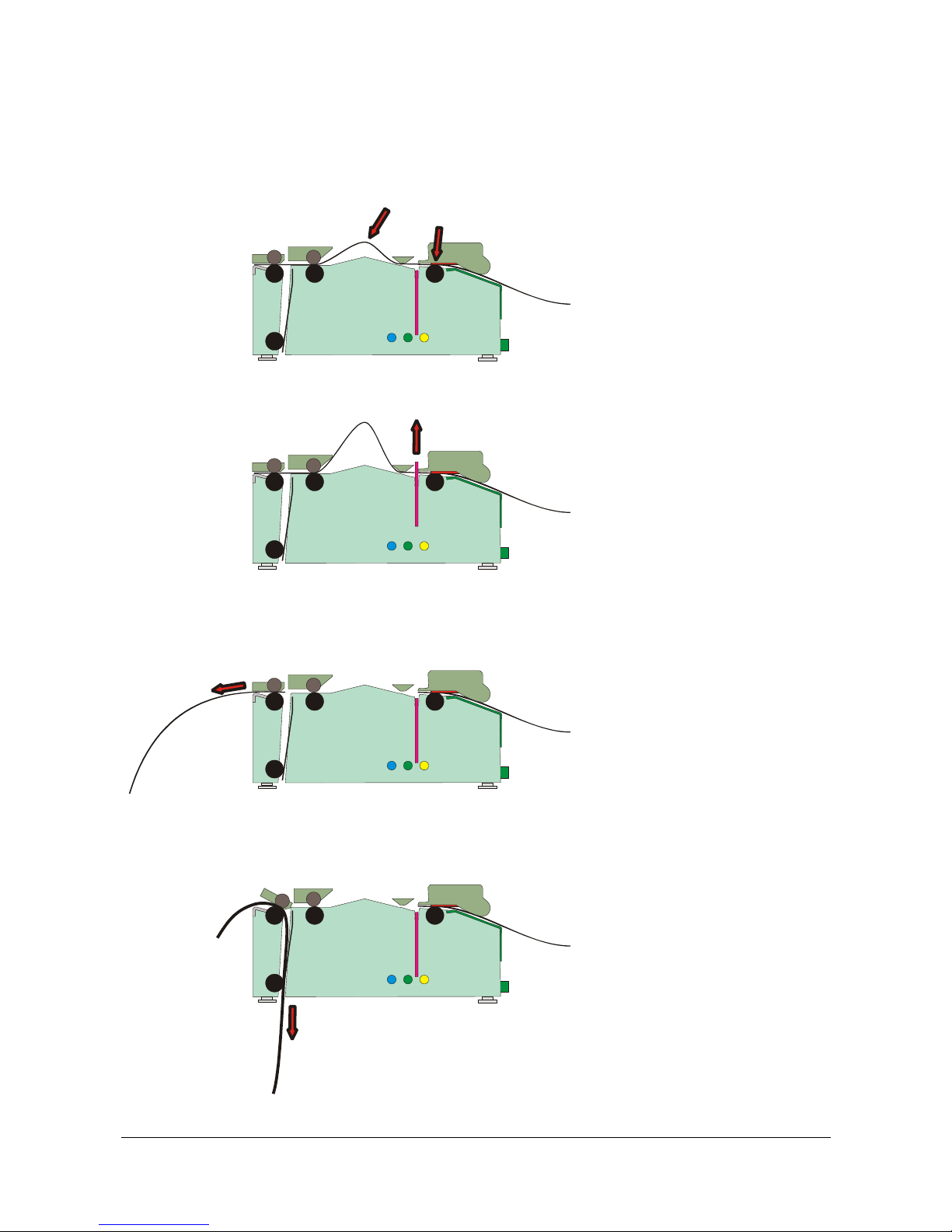
Print
Cut
ٛ
ٛ
Present
Printout
ٛٛ
Store printout
in loop
Retract to wastebasket
ٛ
ٛ
ٛ
Print
Cut
Present
Retract
ٛ
ٛ
2.1.1 Looping presenter
The loop generating presenter
mechanism has many benefits;
•
It handles documents of
various lengths by storing
the printed paper in a loop.
•
It holds the printout until fully
printed and cut before
presenting the completed
printout to the customer.
•
When presented, only the
very end of the printout is
held by the printer so the
customer can easily take the
printout no matter how long
or short it is. You can also
select to eject a portion of
the printout and then use the
pull detector to eject the rest
when the customer pulls in
the paper.
•
The retract-and-retain
function can retract
uncollected printouts and
throw them in a wastebasket
inside the kiosk. Retracts
are reported to the driver so
any remaining data for that
printout can be deleted.
Figure 2 The Swecoin looping presenter
Page 9
Product presentation
8 TTP 2000 Kiosk Printer–Technical Manual 0602
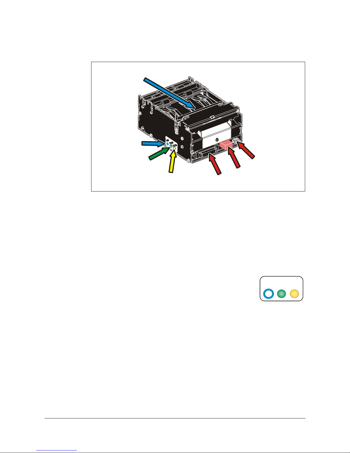
2.2 Controls
Feed Button
Status Indicator
Power Indicator
Printhead lock/
cutter protection
Interface
Connector
Power
Connector
Paper low
Connector
Figure 3 Rear view
The controls are duplicated on both sides of the printer so that they are easily accessible
regardless of how the printer is installed.
2.2.1 Feed button
The
Blue
feed-button has several functions:
•
Short press; eject printout from presenter
•
Longer press; feed, cut, and present a complete page.
Any data in the print buffer will be printed. If the buffer is empty the page will be
blank.
In black mark mode, the page will be synchronized with the black mark.
•
Press and hold while turning on the power, or while opening and closing the
printhead to print a self-test printout. See page 19.
F
e
e
d
P
o
w
e
r
S
t
a
t
u
s
R
Page 10

Product presentation
0602 TTP 2000 Kiosk Printer–Technical Manual 9
2.2.2 Status indicator
●●
The status indicator has several functions:
ON constantly
— the printer is operational
Flashes rapidly
— indicates error. Hold down the feed-forward button and the
number of blinks will reflect the
status-code
.
1 Presenter jam, paper cannot be ejected / retracted
2 Cutter cannot return to home position
3 Out of paper
4 Printhead lifted
5 Paper feed error (under head)
6
Temp error, printhead is above 60
°
C
7 Presenter jam, motor cannot rotate
8 Paper jam during retract
Fast flashes Checksum error, firmware
Steady light Wrong firmware type or target for firmware loading
Status-codes are reset:
1 When the conditions causing them are removed
2 When the printer is turned off/on
3 When the printhead is lifted and then lowered.
Blink, blink, pause, blink, blink
— is the
warning-code
for paper low1
The warning-code is reset automatically when the condition causing it is removed.
2.2.3 Voltage indicator
●●
Green indicator constantly ON: 24 V present
1
This signaling is disabled by default. It can be disabled/enabled by setting parameter p52
Page 11
Installation
10 TTP 2000 Kiosk Printer–Technical Manual 0602
3 INSTALLATION
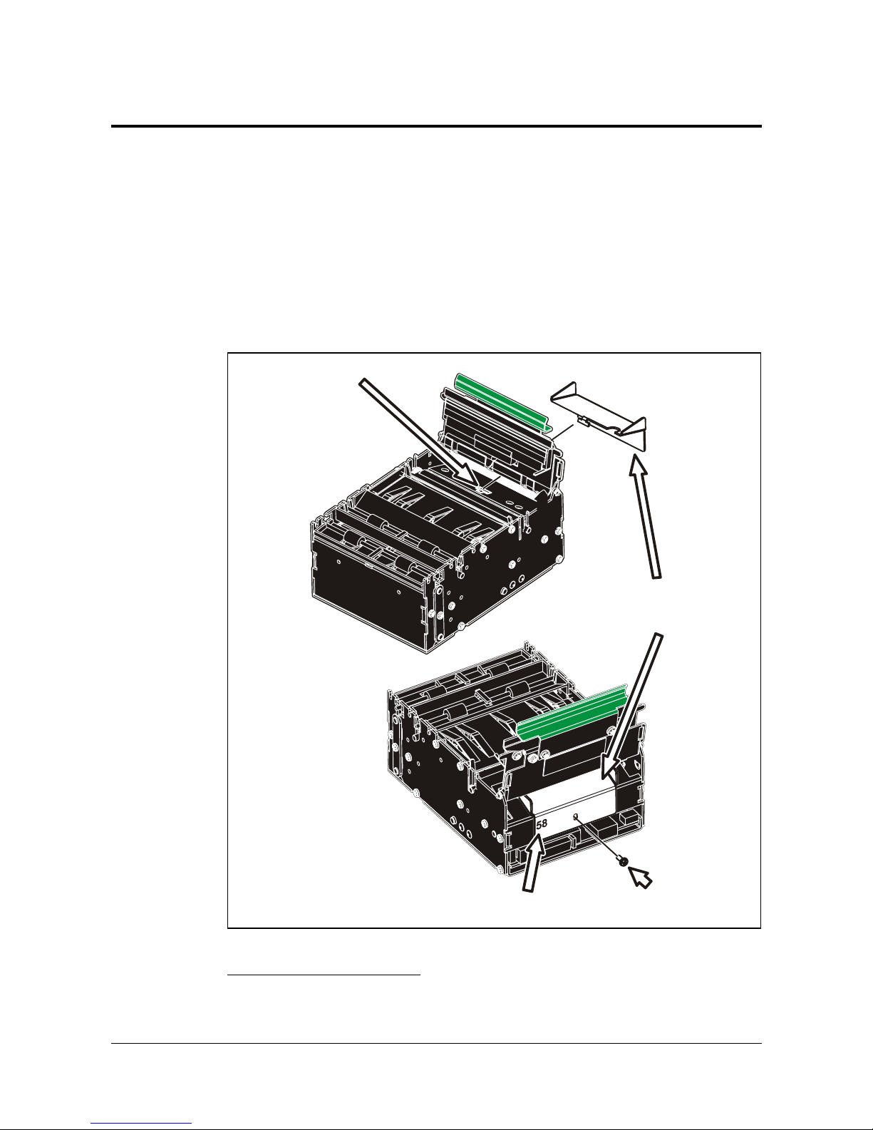
3.1 Installing a paper guide
The paper guide selects if the printer should use 58, 60, 80, or 82.5 mm paper width. The
printer senses what paper guide is fitted and adjusts to it automatically. The TTP 2000
printers are delivered without paper guide fitted.
1. Select the paper guide you want to install
1
2. Open the printhead by pushing green printhead lock plate backwards and lifting
up the printhead, see page 24.
3. Enter the T-shaped tab of the paper guide into the “T”-hole, and fasten the screw.
4. Close the printhead
Paper
Guide
Screw
M3 x 4
Width
in mm
“T”-hole
Figure 4 Fitting a paper guide
1
Evaluation kits contain all input guides available. Regular volume deliveries only contain the appropriate guide for the customer
in question.
Page 12
Installation
0602 TTP 2000 Kiosk Printer–Technical Manual 11
3.2 Installation considerations
The TTP 2000 printer should be installed in some kind of enclosure such as a self-service
kiosk. The footprint and the paper output height is identical to the TTP 1020 /TTP 1030.
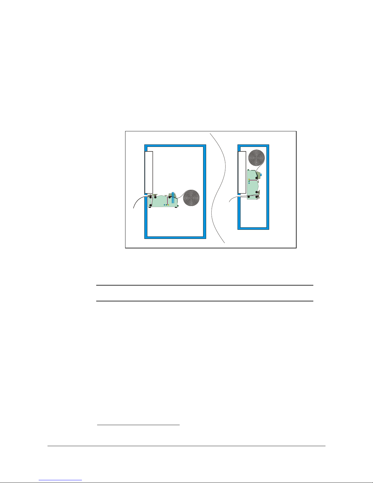
3.2.1 Orientation
The TTP 2000 can be installed horizontally or vertically1. Vertical installation is suitable
for narrow kiosk designs. Here the printer swaps outputs; the normal output becomes the
retract, and the retract output feeds the printout to the customer.
Horizontal
Screen
4
4
33
3
4
3
Screen
V
ertical
Figure 5 The printer can be installed in different orientations. Just set parameter
n57 to the appropriate setting and the printer adapts to its new
orientation.
If you use the Windows driver, a selection in the driver sets horizontal or
vertical mode.
NOTE! — In vertical mode the printer does not loop the paper but stores it hanging
down, then cuts and ejects vertically when the printout is ready.
1
Implemented in firmware version 3.20
Page 13
Installation
12 TTP 2000 Kiosk Printer–Technical Manual 0602
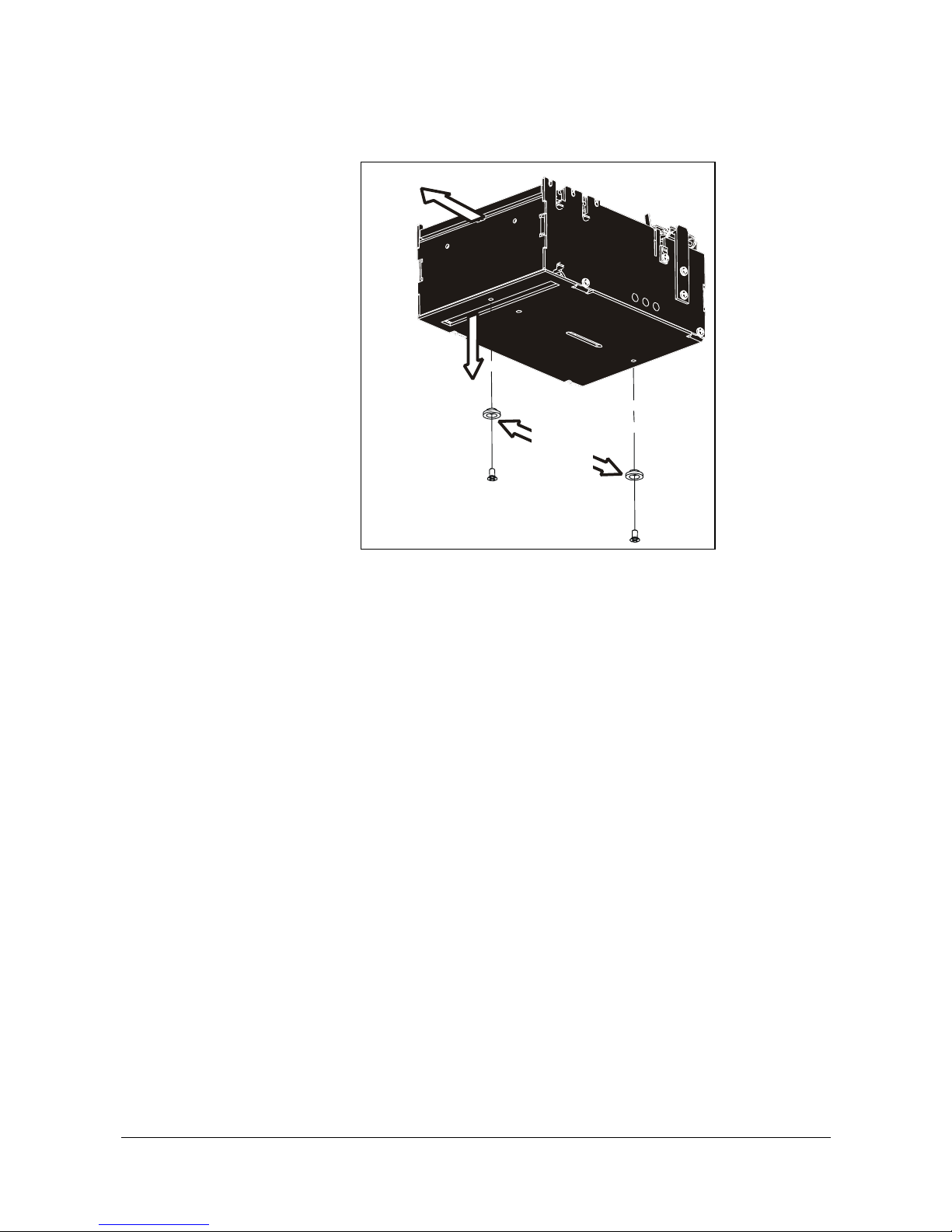
3.2.2 Quick-fit hubs
Retract
exit
Printout exit
Optional
quick-fit
hubs
Figure 6 Front, bottom view
The printers attach to the kiosk using two screws, or just slides in place using the quick-fit
hubs.
Page 14
Installation
0602 TTP 2000 Kiosk Printer–Technical Manual 13
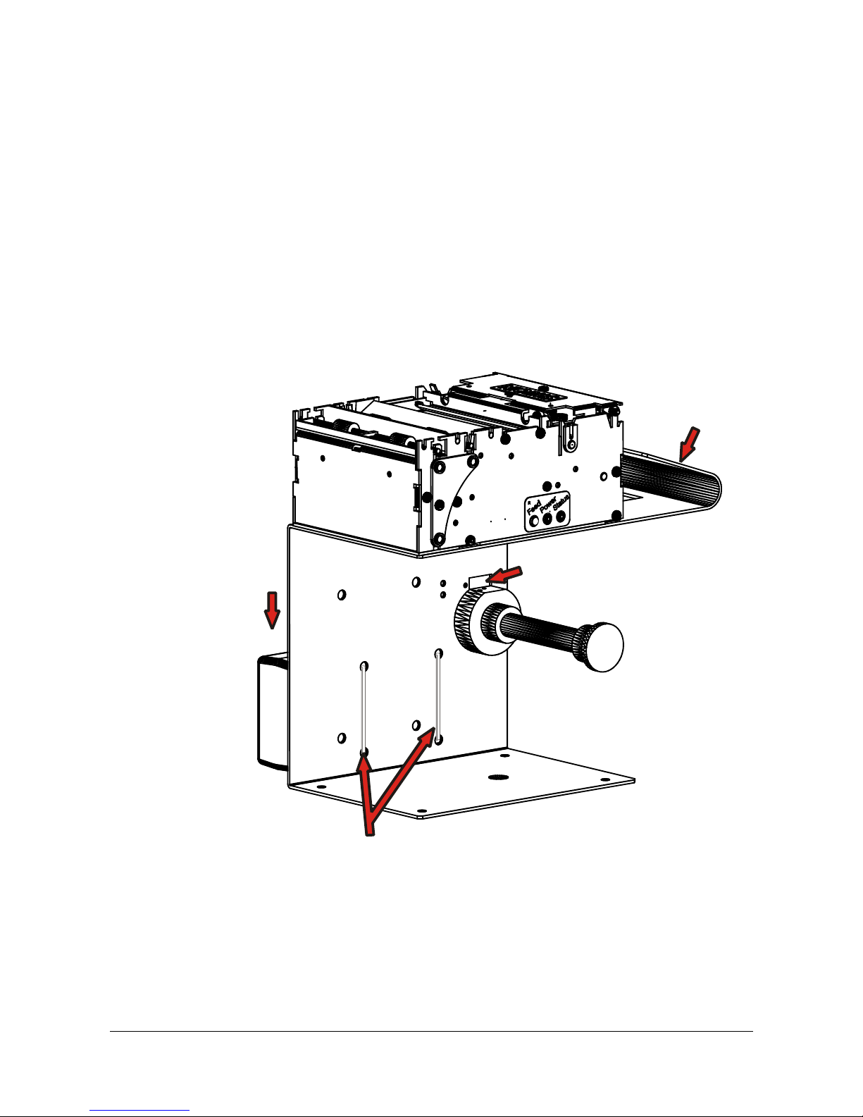
3.2.3 Using a Swecoin roll holder
The Swecoin roll holders fit paper widths, 58 mm, 60 mm, 80 mm, and 82.5 mm without
adjustments, and takes minimum 150 mm rolls.
An example of a Swecoin roll holder is the shelf type that has the quick fit fastening so
you just connect the cables to the printer then slide it onto the roll holder. It also has
additional holes so that you can attach the 75 W PSU with straps, and fit an optional
paper low sensor.
This roll holder both stands stable on your desktop, and can be fastened into your kiosk
and used in normal installations.
More Swecoin roll holders can be found in chapter 10 of this manual.
PSU
space
Space for optional
paper low sensor
Integrated
paper guid
e
Strap holes for fastening PSU
Page 15
Installation
14 TTP 2000 Kiosk Printer–Technical Manual 0602
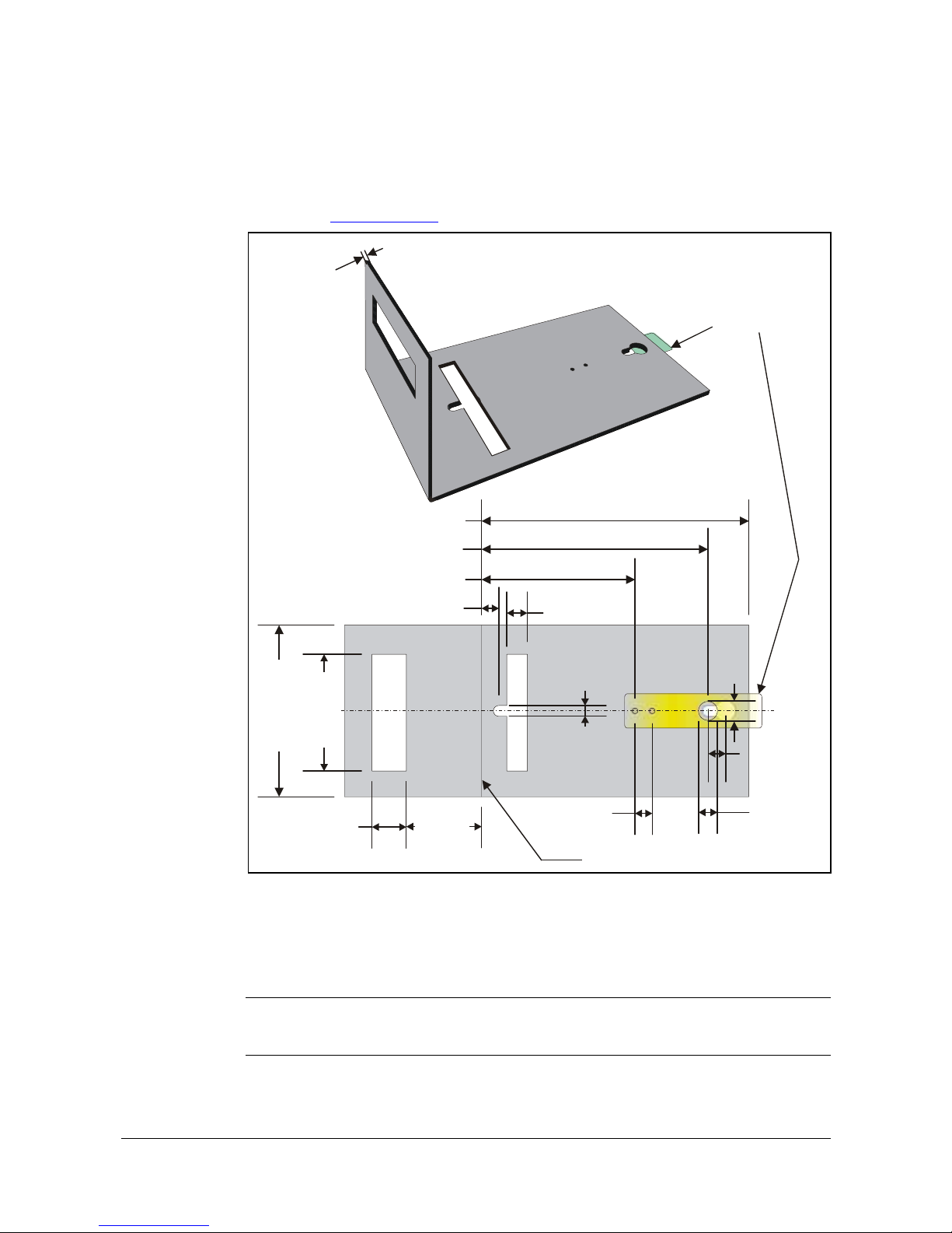
3.2.4 Design you own mounting
The illustration below gives an example of a printer-mounting shelf. See also "printer
Dimensions" on page 90, and the 3D solid models and outline drawings for CAD that are
available on www.swecoin.se
.
20 mm
Paper width
+ 10 mm
44 mm
10 mm
∅
12 mm
∅
6.5 mm
10 mm
90.8 mm
132 mm
156 mm
Leaf spring
01473-000
∅
11 m m
10 mm
1.
5
m
m
Add material for corner radius
Min. 100 mm
Center
10 mm
Figure 7. Example of a simple shelf for fastening a standard printer using quick-fit hubs and a leaf spring
retainer (order No. 01473-000)
Additional space is required for paper loading and paper jam removal. Consider mounting
the printer on a movable platform so that the printer can be maintained outside the printer
enclosure.
HINT! — We recommend you to make the output slot and the retract slot 97 mm wide.
This way you will have no problem using all paper widths that the TTP 2000
series of printers can handle.
Paper width
+ 10 mm
Page 16
Installation
0602 TTP 2000 Kiosk Printer–Technical Manual 15
3.2.5 Electrostatic discharges, and earth currents
Preventing ESD and earth currents from affecting the printer operation
requires
proper
connection of the printer chassis to protective earth through a mounting platform or
through a separate earth conductor.
3.2.6 Ambient light
There is an optical sensor 20 mm behind the paper exit at the front of the printer.
To ensure proper printer operation, design the printer enclosure so that it prevents direct
sunlight or light from indoor lamps from reaching the sensor through the paper exit.
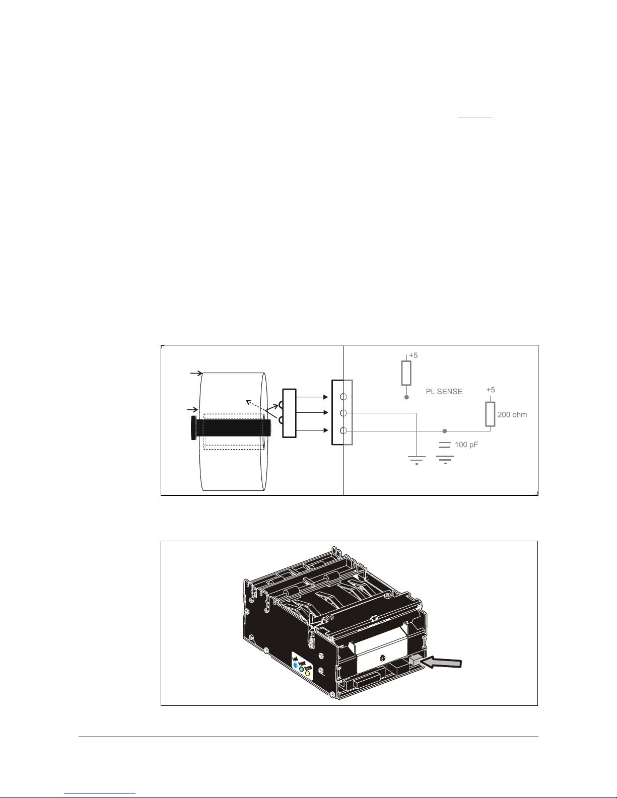
3.3 Installing a paper-low sensor (option)
A paper-low sensor alerts the system when a certain length of paper remains on the roll.
The purpose of this sensor is to get an early alert so that you can replace the paper roll in
time in remotely located kiosks.
All paper roll holders supplied by Swecoin can be equipped with paper-low sensors. Just
install it, and connect the cable to the paper low connector at the back of the printer.
+5
+5
Paper-low
sensor
2
3
1
J10
PL SENSE
SW97081F
200 ohm
100 pF
Paper roll
New
Near
end
Roll holder shaft
Gray = Connection
inside printer
Figure 8. Paper-low sensor connection
Paper low
connector
Figure 9. Location of paper-low connector
Page 17
Installation
16 TTP 2000 Kiosk Printer–Technical Manual 0602
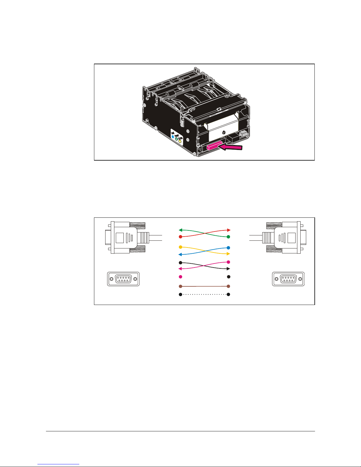
3.4 Connecting to the computer
Interface
connector
Figure 10. Location of interface connector
3.4.1 TTP 2010
Connect a Swecoin serial cable, ordering No. 10825-000, between the printer and the
computer to be used. We strongly recommend using the Swecoin cable because many
incompatible cables are available.
Printer
PC
Female
594837261
Female
594837261
2RxDRxD2
3TxDTxD3
9RIRI9
6DSRDSR6
8CTSCTS8
4DTRDTR4
7RTSRTS7
1DCDDCD1
5GNDGND5
Serial Cable 10825-000
Figure 11. Serial interface cable 10825-000. Dotted leads are not connected in the printer.
To be able to connect the cable in any direction, make symmetrical cables.
Page 18
Installation
0602 TTP 2000 Kiosk Printer–Technical Manual 17
3.4.2 TTP 2020
Connect the printer to the parallel port of the computer to be used.
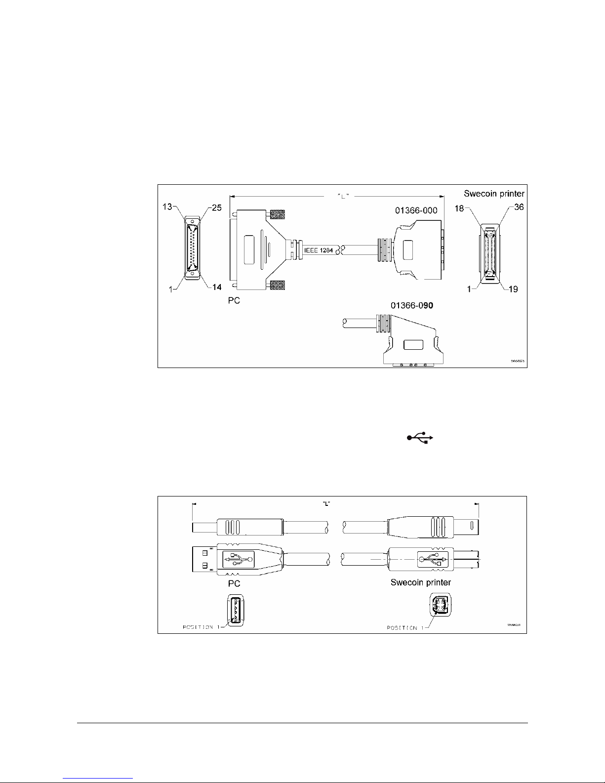
Use cables 01366-000 or 01366-090, see the illustration below.
The printer end of the cable should have an IEEE-1284 type C, 36-pole mini Centronics,
with clip latches, see page 76 for pin assignment.
Figure 12. IEEE-1284 cable with type A and type C connectors
3.4.3 TTP 2030
Connect J13 of the printer to the USB port of the computer or the USB hub to be used.
USB connectors can be recognized by the following symbol:
.
Connector J13 is a 4-pin USB type B connector. See Table 8 for pin assignment.
A suitable cable is available from Swecoin, ordering number 01542-000.
Figure 13. USB cable with type A and type B connectors
Page 19
Installation
18 TTP 2000 Kiosk Printer–Technical Manual 0602
3.5 Connecting the power
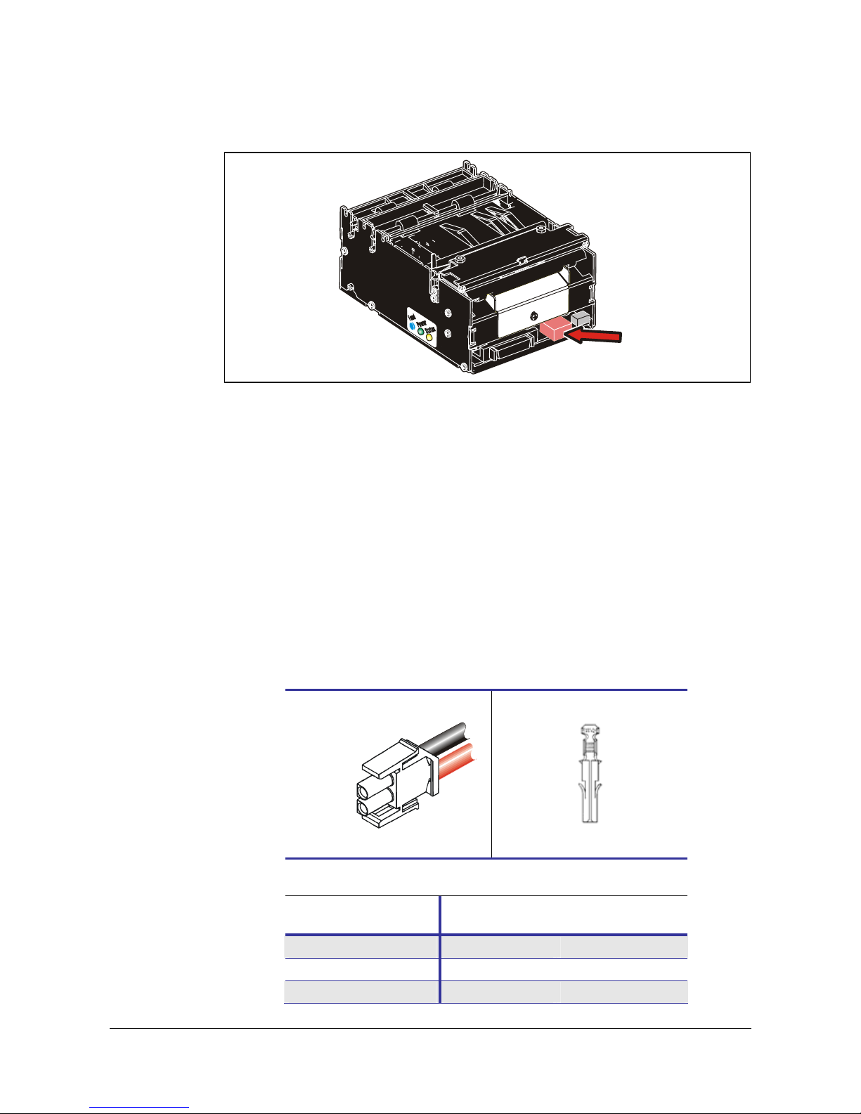
Power
Connector
Figure 14. Location of power connector
Using a Swecoin power supply (page 95):
1. On power supplies with line voltage selector, make sure it is set to your local line
voltage.
2. Connect the cable from the power supply the power connector on the back of the
printer.
3. Connect the power cable to the line outlet.
4. Turn ON the power.
If you use another type of power supply unit, 24 V cables are available from Swecoin AB,
order No. 01370-000. If you make cables of your own, connect the voltages according to
the following illustration. Note that protective ground and minus output should
not
be
interconnected in the power supply. At the printer end of the cable, use an AMP Mate-NLok connector housing and two contact-sockets:
Housing: AMP No. 350777-1
GND
+24 V
Socket: AMP No. 350689-1
Figure 15. Power connection
Mode
58-60 mm
paper width
80 – 82.5 mm
paper width
Idle
150 mA 150 mA
Standard text printing
2 A average 3 A average
All black printing
6 A 8.5 A
Table 1. Current consumption
Page 20
Installation
0602 TTP 2000 Kiosk Printer–Technical Manual 19
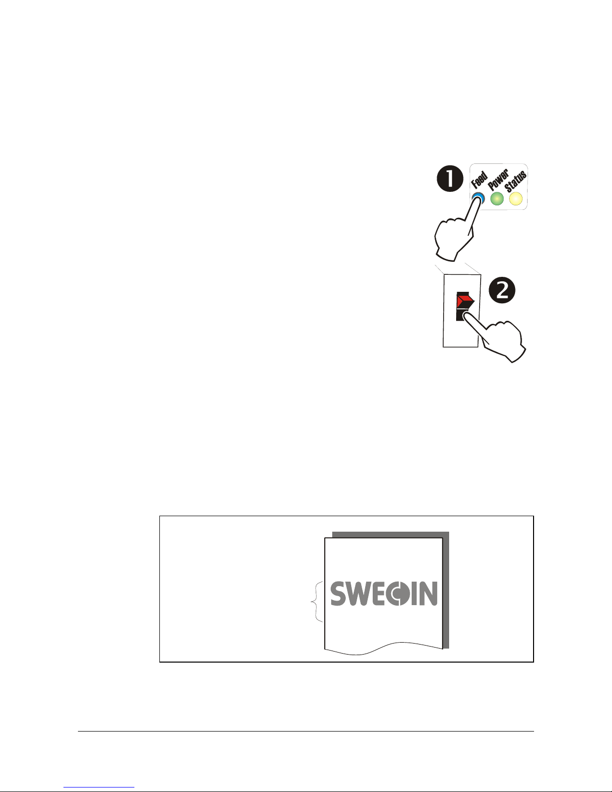
3.6 Making a test printout
1. Switch OFF the power.
2. Hold the feed-forward button depressed while powering ON
the printer. Keep the button depressed until printing starts.
This produces a printout showing the firmware program version
and date, control board revision number and serial number,
name of loaded fonts and logotypes, and the parameter
settings.
3. Each successive press of the button will produce a test
printout.
Switch the printer OFF and ON again to exit self-test mode.
If a power button is not available for the printer, follow the
below procedure:
1. Lift the printhead
2. Hold the FF-button pressed while lowering the head
and hold it pressed while an auto load of paper is done
3. Release the button and a self-test printout will be printed
4. The printer exits self-test mode and goes on-line
3.6.1 Customizing the self test printout
The self test printout starts with a text line, and then a Swecoin logotype. This logotype is
just a printout of logotype No. 0., so if you want to personalize the self test printouts in
your installation, delete all logotypes and store your own logotype as No. 0.
See also logotypes on page 56.
www.swecoin.se
TTP 2020 Kiosk Printer
Logotype No. 0
Figure 16. Logotype No. 0 is printed on the self test printout.
1
0
Self-test
Page 21
Installation
20 TTP 2000 Kiosk Printer–Technical Manual 0602
3.7 Installing a printer driver
Printer drivers for Linux, and Microsoft Windows™ are available on the Swecoin web site
www.swecoin.se
, or on disk from Swecoin, see page 2 for address. Please follow the
installation instructions that accompany the drivers.
3.7.1 Status monitoring through Windows1
Status can be fetched from a language monitor (20x0mon.dll) that is installed into
Windows with the driver. Documentation of the language monitor is available on the
drivers’ page on the Swecoin web site.
If you want to monitor status through the language monitor,
make sure that the printer is
selected as default printer
, and that bi-directional support is enabled in the port section of
the driver settings.
NOTE! – On TTP 2020, parameter p5 should be set to 1 to make status
replies possible when paper is out. See page 62.
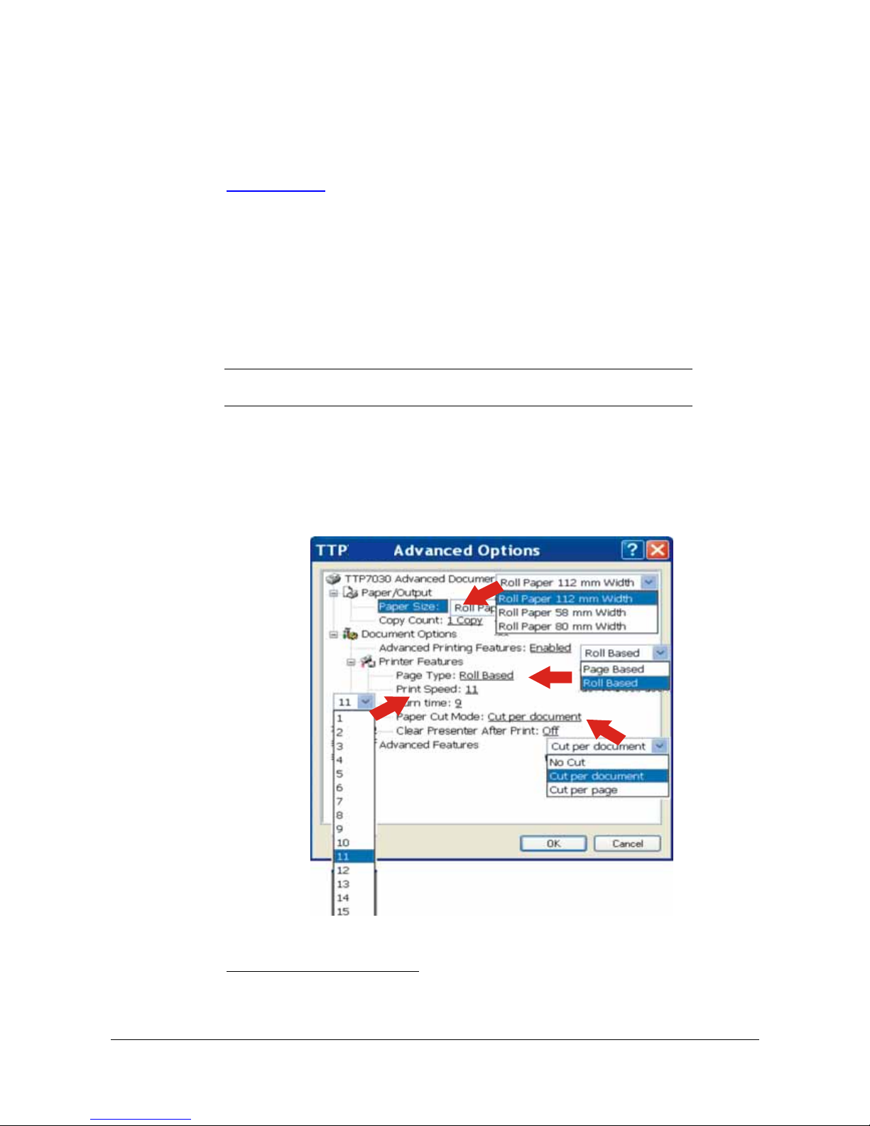
3.7.2 Settings available in the driver
The looks of the dialogue boxes vary between driver versions, but essentially the same
settings can be made.
You start with the Printing Preferences window. Here you find the portrait/landscape
setting, and an advanced button.
Figure 17. Example of setup window
1
If a print server is used, it must support true binary communications, bi-directionally. If you use incompatible print servers,
bidirectional support must be disabled in the driver properties.
Page 22

Installation
0602 TTP 2000 Kiosk Printer–Technical Manual 21
The advanced button contain the Swecoin specific settings:
Paper/Output
•
Paper size: Roll paper 58 - 60 mm / 80 – 82.5 mm
•
Copy Count: 1 to 9999
Document options
Advanced printing features:
Enabled
/ disabled
Printer features:
•
Page Type:
Page based
/Roll based/Black Mark1
•
Printing Speed: 1 to 19
•
Burn Time: 1 to15
•
Retract Setting: Eject | Eject after x sec., Retract | Retract after x sec.2
•
Paper Cut Mode: No Cut /
Cut per document
/ Cut per page3
•
Clear Presenter After Print: On /
Off
•
Hold Page After Print: On /
Off
4
•
Vertical mount On /
Off
•
Slow present On /
Off
Advanced features
•
Advance After Print: 0-100 mm (
10 mm
)5
•
Paper Eject: 0-100 mm (
30 mm
)6
•
Reverse Before Print: 0-100 mm (
0 mm
)7
•
Black mark Settings:8
o
Minimum black mark: 0-100 mm (
3 mm
)
o
Maximum black mark: 0-100 mm (
16 mm
)
o
Cut position: 0-100 mm (
25 mm
)
•
Scaling: 10-400% (
100%
)9
•
Contrast/brightness
1
Page based give the page size set in the Paper Size setting (in server preferences, forms). Roll based saves paper by cutting
after the last print on the page. Black Mark synchronizes with preprinted marks on the back of the paper.
2
Interpret like; Retract page in presenter when a new page is printed, and retract uncollected pages after xx seconds.
3
“Cut per page” give three pages when a 3-page document is printed, while “Cut per document” give one long page with all
information printed on it.
4
Holds printing of consecutive pages until the customer takes the presented page. If a page is not taken within the set retract
timeout, the rest of the print job is deleted from the print queue in Windows This requires bidirectional communication.
5
Paper Advance is advance before cut, that is bottom margin.
6
This eject is in addition to the standard 50 mm, so a setting of 100 gives 150 mm total eject.
7
Paper reverse is reverse before print, and reduces the 9 mm top margin with the value entered here. So a setting of 4 gives
9 – 4 = 5 mm top margin.
8
Black mark synchronization ON /OFF is selected with Page Type.
9
Scaling to e.g. 99% can be used when you need to print forms with fixed page length that otherwise would not fit on a page.
Page 23
Operation
22 TTP 2000 Kiosk Printer–Technical Manual 0602
4 OPERATION
4.1 Installing a paper roll
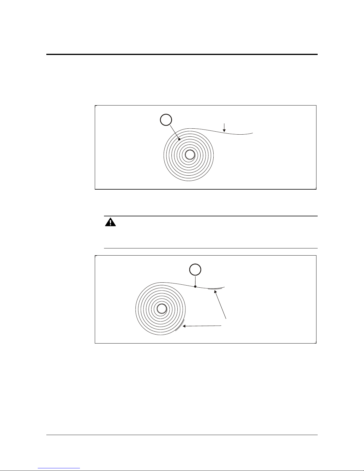
1. Turn the new paper roll as shown. The paper should be inserted into the printer with
the temperature-sensitive side up.
Temperature-sensitive
coating
SW96074A
1
Figure 18. Turn the paper roll so that the paper leaves the roll from the top
2. Tear off a full turn of the paper from the new paper roll.
CAUTION!
This is important since the outer end of the paper is usually fixed to the roll with some
type of glue or self-adhesive substance that might otherwise cause paper jam or even
print head damage.
SW96075B
2
Glue or similar
substance
Figure 19. Tear off a full turn from the new paper roll
3. Make sure the printer is turned ON.
Page 24
Operation
0602 TTP 2000 Kiosk Printer–Technical Manual 23
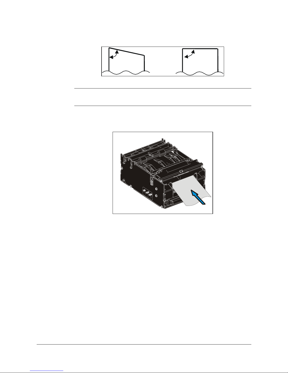
4. Cut the paper in a suitable angle:
90º
Thermal side (top)
70º
Thermal side (top)
Cut off at
a 70º-90º
angle
Figure 20. Suitable paper edge for auto load
NOTE 1! — The paper sensor is at the same side as the interface connector. If the paper
is cut in a direction opposite to that as shown in the figure above, the sensor
will not detect the paper.
5. Insert the paper through the paper entry opening at the back of the printer.
The printer will now feed, cut and eject a printout, and then automatically go on-line.
Figure 21. Insert the new paper
Page 25
Operation
24 TTP 2000 Kiosk Printer–Technical Manual 0602
4.2 Clearing paper jams
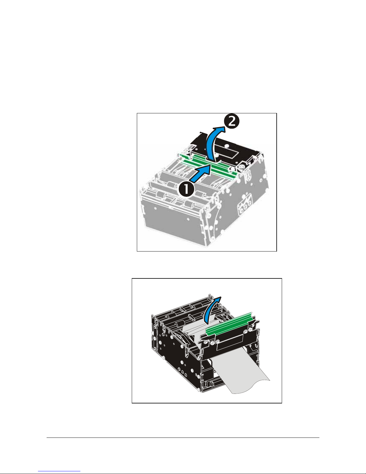
Should a paper jam occur, follow the procedure below:
Open the printhead by:
1. Press the green release lever toward the rear of the printer.
2. Lift the head.
Figure 22. Opening the printhead
3. Remove any paper trash and close the printhead.
ٛ
Figure 23. Remove paper trash
Page 26
Programming
0602 TTP 2000 Kiosk Printer–Technical Manual 25
5 PROGRAMMING
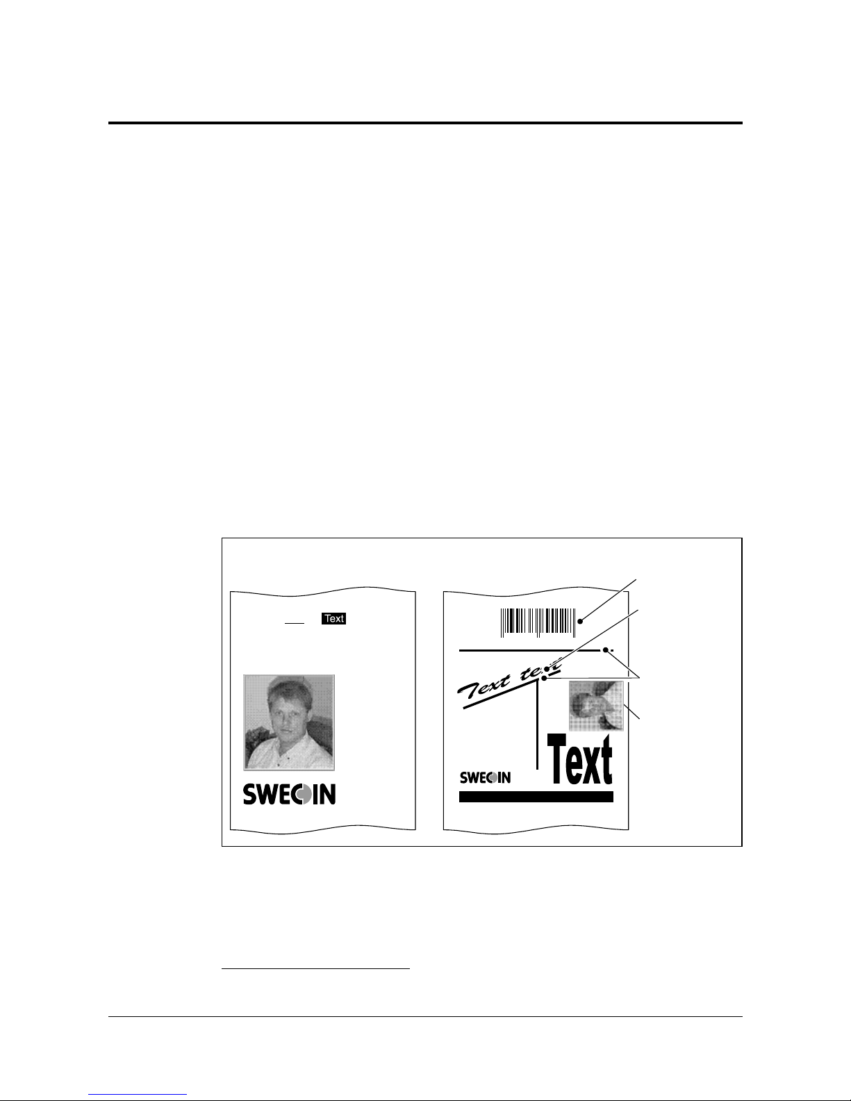
There are two completely different ways of setting up the printout: Text oriented and
driver oriented style.
Text oriented
The printout can be seen as the page of a simple word processor. You send text and
graphics to the printer, which prints the information in the same sequence as the data is
received. Design features are limited to the font stored in the flash PROM of the printer.
There are two text cursors, one for portrait, and one for landscape
1
. The start positions of
the cursors are the upper left corner for the portrait cursor, and the upper left corner for
the landscape cursor, see Figure 24. You can switch between these cursors at any time;
the cursor will retain its last position on the ticket.
Driver oriented
All TTP 2000 printers can print documents through a driver. When a Windows driver is
used, you can use any Windows program to design the ticket with text, graphics, bar
codes or whatever you want to print and in any orientation you want.
The Windows driver issues all the necessary commands. By setting up printing
preferences in the driver you select how the printer should cut and present the printout.
Sw98073
Text can be printed in
any orientation, font,
and size.
Graphics can be rotated,
color images converted
to gray scale, etc.
Lines can be added.
Tex t
text
text text text text
text text text text
text
1 234567 890128
Bar codes can be added.
Text text
text text
text text
text text
text text
Text text text text text text text text text text
Tex t r e ce i p t
Driver (Windows) receipt
Text text text text text text text text text text
text text text text text text text text text text
text text text
text text text text text text text text text text
Figure 24. Printout styles
1
Only available in Fixed Document Mode. See parameter n36.
Page 27
Programming
26 TTP 2000 Kiosk Printer–Technical Manual 0602
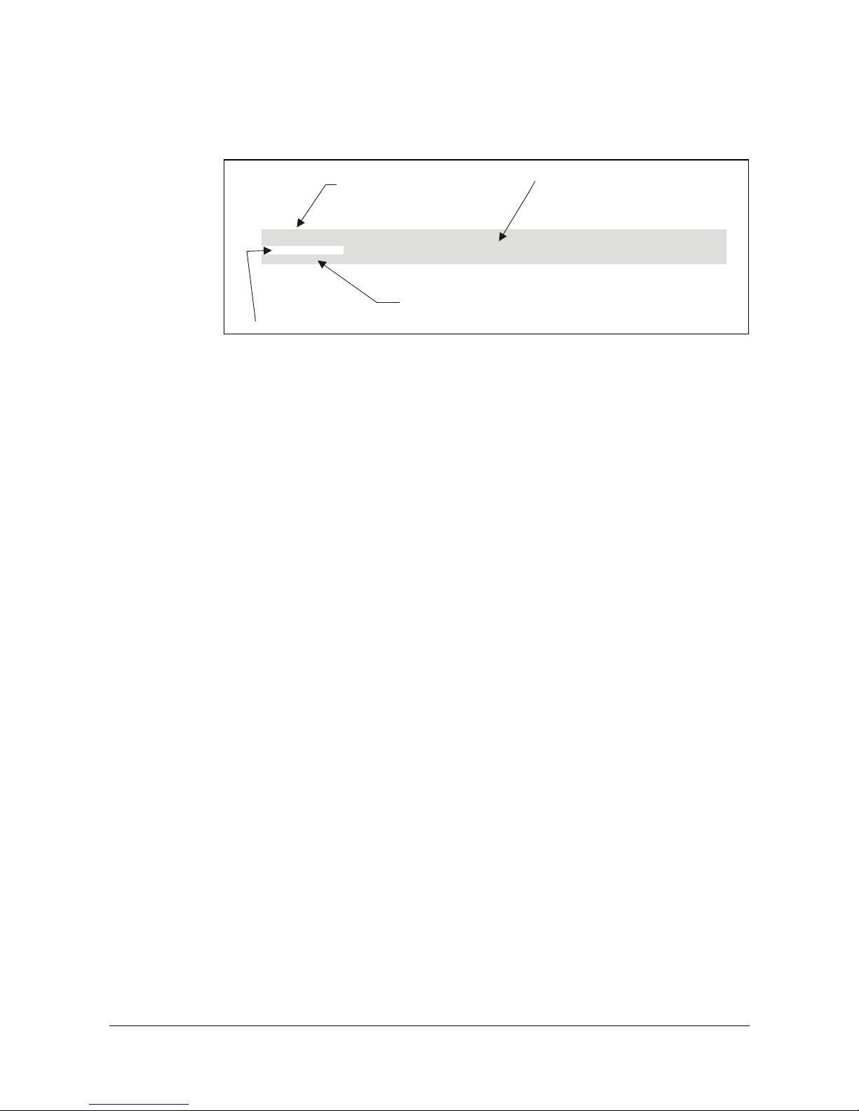
5.1 How the commands are described
ESC ! n1
1B 21 n1 Hex
27 33 n1 Dec
Select font
Mnemonic
Hex representation of command
Decimal representation of command
Purpose of command
SW 03002
5.1.1 Mnemonic
Is the popular command name that should be easy to remember.
5.1.2 Hex
Give the command in hex representation
5.1.3 Decimal
Give the command in decimal representation
5.1.4 Values
n1, n2, etc. represents values that you set with the commands. What you should enter
here depends on what you want the command to do.
5.1.5 Examples
Command examples are formatted in
Courier
and typed in the same way as used in the
Swecoin TTP editor:
<ESC>&P<001><019>
Where
<ESC>
means the escape character 27 decimal (hex 1B). Numbers between less-
than and greater-than characters, for example
<001><019>
, means 1 and 19 decimal.
When the numbers indicate a hex value, h is appended to the number (
<01h><13h>
).
EXAMPLE:
<065>, <65d>
,
<41h>
and A are four different ways of expressing the character A.
Page 28

Programming
0602 TTP 2000 Kiosk Printer–Technical Manual 27
5.2 Summary of control codes & escape sequences
Command Hex Decimal Function Page
BS
08 8 Backspace
32
CAN
18 24 Cancel
32
CR
0D 13 Carriage return
32
EM
19 n1 25 n1 Enforced Clear Presenter
41
ENQ
05 5 Clear Presenter
41
ESC ACK
1B 06 n1 27 6 n1 Acknowledge Marker
53
ESC !
1B 21 n1 27 33 n1 Select Font
30
ESC #
1B 23 27 35 Calibrate Blackmark Sensor
29
ESC & 000
1B 26 00 27 38 0 Load Font
44
ESC & 001
1B 26 01 27 38 1 Load Logotype
43
ESC & 004
1B 26 04 27 38 4 Store current Parameter Values
43
ESC & C
1B 26 43 27 38 67 Erase all Fonts
44
ESC & D
1B 26 44 27 38 68 Erase Fonts 4 to 7
44
ESC & F
1B 26 46 27 38 70 Recall Parameter Profile
44
ESC & L
1B 26 4C 27 38 76 Erase all Logotypes
43
ESC & P
1B 26 50 n1...n2 27 38 80 n1...n2 Set Parameter Value
45
ESC ?
1B 3F 27 63 Reset (full)
43
ESC @
1B 40 27 64 Reset (initialize)
43
ESC b
1B 62 n1...n5 27 98 n1...n5 Print Bitmap at XY-position
36
ESC B
1B 42 n1 27 66 n1 Bold
31
ESC B C
1B 42 43 n1 27 66 67 n1 Barcode Clear
35
ESC B S
1B 42 53 n1...n11 27 66 83 n1...n11 Barcode field Specify
34
ESC B W
1B 42 57 n1 27 66 87 n1 Barcode Write
35
ESC d
1B 64 n1 27 100 n1 Make n Linefeeds
33
ESC ENQ 001
1B 05 01 27 5 1 Status Enquiry
46
ESC ENQ 002
1B 05 02 27 5 2 Paper-near-end Enquiry
47
ESC ENQ 004
1B 05 04 27 5 4 Fonts and Logotype Enquiry
47
ESC ENQ 005
1B 05 05 27 5 5 Sensor Enquiry
48
ESC ENQ 006
1B 05 06 27 5 6 Status Report
49
ESC ENQ 007
1B 05 07 27 5 7 Firmware-version Enquiry
50
ESC ENQ 009
1B 05 09 27 5 9 Serial-number Enquiry
50
ESC ENQ 010
1B 05 0A 27 5 10 Control board revision Enquiry
50
ESC ENQ 011
1B 05 0B 27 5 11 Head temperature Enquiry
50
Page 29

Programming
28 TTP 2000 Kiosk Printer–Technical Manual 0602
ESC ENQ 012
1B 05 0C 27 5 12 Bootware version Enquiry
50
ESC ENQ c
1B 05 63 27 5 99 Device ID Enquiry
52
ESC ENQ E
1B 05 45 27 5 69 Read extended status
52
ESC ENQ p
1B 05 50 n1 27 5 80 n1 Parameter-setting data Enquiry
52
ESC ENQ P
1B 05 50 n1 27 5 80 n1 Parameter-setting data Enquiry
52
ESC f
1B 66 n1 27 102 n1 Presenter loop ON/OFF/max length
42
ESC FF
1B 0C n1 27 12 n1 Eject (run presenter)
41
ESC g
1B 67 n1...n5 27 103 n1...n5 Print Logotype
38
ESC h
1B 68 n1 27 104 n1 Text Height
31
ESC i
1B 69 n1 27 105 n1 Italics
31
ESC j
1B 6A n1 27 106 n1 Paper Reverse
39
ESC J
1B 4A n1 27 74 n1 Paper Advance
39
ESC L
1B 4C n1 27 76 n1 Print Logotype at Current Position
38
ESC N
1B 4E n1 27 78 n1 Align Text 30
ESC NUL
1B 00 27 0 Load Firmware
45
ESC o
1B 6F n1 27 111 n1 Text and logotype orientation
30
ESC p
1B 70 27 112 Print
39
ESC P
1B 50 n1 27 80 n1 Print Self-test Printout
39
ESC r
1B 72 n1...n9 27 114 n1...n9 Print Ruler Line
37
ESC RS
1B 1E 27 30 Cut only, no Eject
40
ESC s
1B 73 n1 27 115 n1 Send dot-line, 203 dpi
36
ESC t
1B 74 n1...n5 27 116 n1...n5 Print Text at XY 32
ESC T
1B 54 n1 27 84 n1 Reversed/Inversed Text
31
ESC u
1B 75 n1 27 117 n1 Underline
31
ESC w
1B 77 n1 27 119 n1 Text Width
31
ESC Z
1B 5A 27 90 Go to next Top of Form
29
FF
0C 12 Form Feed
33
HT
09 9 Horizontal Tabulation
33
LF
0A 10 Linefeed
33
RS
1E 30 Cut and Eject
40
US
1F 031 Partial cut
40
Table 2. Control codes & escape sequences in alphabetical order
NOTE! – In all responses from the printer the most
significant byte (MSB) is transmitted first
Page 30

Programming
0602 TTP 2000 Kiosk Printer–Technical Manual 29
5.3 Software command syntax
The commands in this section are grouped after what they do, and these groups are
sorted in a theoretical usage sequence. It starts with commands for specifying the printed
page — through text-and-graphics commands — to cut-and-present commands. System
and status commands are presented at the end.
5.3.1 Black mark (top-of-form) commands
See also “Aligning preprint and thermal print” on page 69.
ESC #
1B 23 Hex
27 35 decimal
Calibrate Blackmark Sensor
Looks for a black mark, measures the contrast of the mark and sets parameter n51 to a
suitable value for the detected voltage, then reverses to the start position.
To make the calibration permanent, send
ESC & 4h
, store parameter values.
NOTE! – Be sure to first set up the length of the black mark and the distance
between two black marks in the parameter setup.
ESC Z
1B 5A Hex
27 90 Decimal
Go to next Top of Form
In black mark mode,
an ESC Z
starts looking for a black mark at the current position and
continues for one page length. If no black mark is found, the printer stops and bit 3 in
status byte 2 is set to 1 (See
ESC ENQ 6h
).
When black mark mode is disabled, ESC Z will perform a form feed.
Page 31

Programming
30 TTP 2000 Kiosk Printer–Technical Manual 0602
5.3.2 Text commands
Text received by the printer is printed with the currently selected font and font attributes.
Text exceeding the page width is wrapped with the line spacing selected.
ESC o n1
1B 6F n1 hex
27 111 n1 decimal
Text and Logotype Orientation
Changes the orientation of text and logotypes.
n = 0 Gives portrait orientation
n = 1 Gives landscape orientation
Portrait and landscape can be mixed on the same printout. There are two cursors, one for
portrait and one for landscape. The cursor always starts at the top left corner of the
document. Looking at the paper when it exits the printer, the portrait cursor is at the top
left corner of the printout, moving to the right as text is typed, while the landscape cursor
is at the top right corner, moving downwards.
NOTE! — Landscape orientation can only be used with Fixed Document Mode.
ESC N n1
1B 4E n1 hex
27 78 n1 decimal
Align Text
Changes the alignment of text and logotypes.
ESC N 0
= Left
ESC N 1
= Center
ESC N 2
= Right
ESC ! n1
1B 21 n1 hex
27 33 n1 decimal
Select Font
This command selects one of eight fonts. The font design depends on which fonts have
been loaded
1
into the printer. Make a test printout to see which fonts are available in your
printer.
ESC ! 0
selects normal font (font 0)
ESC ! 4
selects font 4
ESC ! 1
selects font 1
ESC ! 5
selects font 5
ESC ! 2
selects font 2
ESC ! 6
selects font 6
ESC ! 3
selects font 3
ESC ! 7
selects font 7
Table 3. Font selection commands
Lines, too long to be printed in the selected font, are automatically wrapped around.
Different fonts can be used on the same line.
Selecting an empty font location, will set bit 4 of byte 1 in the status enquiry response to ”1".
See “Parameter setting data enquiry” on page
52
.
NOTE! — If more than 379 characters are sent to the printer before an LF, the
first part of the buffer contents is printed-out automatically. The text is
formatted according to the already received formatting commands.
1
For font loading, see “Font loading” page 44.
Page 32
Programming
0602 TTP 2000 Kiosk Printer–Technical Manual 31
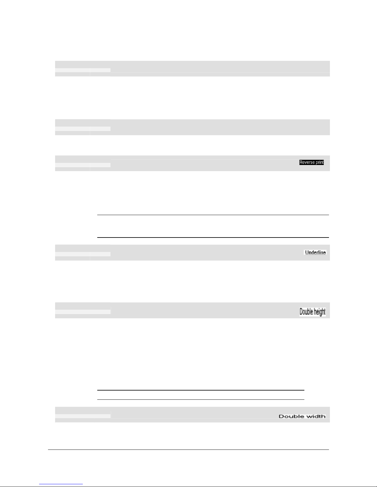
ESC B n1
1B 42 n1 Hex
27 66 n1 decimal
Bold
Normal Bold
n = 0 Turns OFF bold (Normal)
n = 1 Turns ON
bold
Bold is designed for normal character width and shows less and less as the width
increases.
ESC i n1
1B 69 n1 Hex
27 105 n1 decimal
Italics
Normal Italics
n = 0 Turns OFF Italics (Normal)
n = 1 Turns ON
Italics
ESC T n1
1B 54 n1 Hex
27 84 n1 decimal
Reversed/Inversed Text
Selects normal or reversed print.
n = 0 Gives normal print, black on white
n = 1 Gives reversed print, white on black
Single words, characters, or complete text lines can be reversed.
NOTE! – Reverse text and underline XOR's the background with the foreground. This
means that the order in which the commands are issued affect the printout if
one text overlaps another.
ESC u n1
1B 75 n1 hex
27 117 n1 decimal
Underline
n = 0 Turns OFF underline
n = 1 Turns ON a 1 pixel wide underline
n = 2 Turns ON a 2 pixel wide underline, etc. up to n=7.
Characters, single words, or complete text lines can be underlined.
ESC h n1
1B 68 n1 hex
27 104 n1 decimal
Text Height
Applicable n values are 000 — 015.
n = 1 Increases the character height to 2 times the basic character height.
n = 2 Increases the character height to 3 times the basic character height etc.
n = 0 Resets the character height to the basic character height.
In combination with variable character width (
ESC w n
), give highly legible characters
depending on the font to which the command has been applied.
Different fonts and heights can be mixed on the same print line.
NOTE! – DO NOT use multiple height/width attributes when printing bar codes .
ESC w n1
1B 77 n1 hex
27 119 n1 decimal
Text Width
Applicable n values are 000 — 007.
n = 1 Increases the character width to 2 times the basic character width.
Page 33

Programming
32 TTP 2000 Kiosk Printer–Technical Manual 0602
n = 2 Increases the character width to 3 times the basic character width etc.
n = 0 Resets the character width to the basic character width.
In combination with variable character height (
ESC h n
), give highly legible characters
depending on the font to which the command has been applied.
Different fonts and widths can be mixed on the same print line.
NOTE! – DO NOT use multiple height/width attributes when printing bar codes .
ESC t n1...n5 data
1B 74 n1...n5 data hex
27 116 n1...n5 data decimal
Print Text at XY
Prints a text string at the specified X-Y position. The string will use the formatting set by
font, reversed, width, height, bold, italics, and underline commands.
n1n2 Two byte definition of the X print position (in pixels).
n3n4 Two byte definition of the Y print position (in pixels).
n5 The number of characters in the string.
data The text string. The length must be exactly the number of characters specified by
n5, otherwise the printer will stop, waiting for more characters.
After the string has been printed, the cursor will return to the position it had before the
string command was issued.
NOTE 1! —
ESC t
only works with fixed document mode (p36=0).
NOTE 2! —
ESC t
clears any text preceding it on the same line.
Commands will not be cleared.
BS
08 Hex
8 Decimal
Backspace
Moves the print-position one step to the left. Backspace can be used to combine
characters. For instance to print a
Ø
, send text commands
O
BS
/
to the printer, and the
slash will overprint the O.
Only one backspace can be used at a time. Excessive backspaces will be ignored.
CAN
18 hex
24 decimal
Cancel
Cancels text and attributes sent before the
CAN
command on the same line.
Commands, are not cancelled.
CR
0D hex
13 decimal
Carriage Return
By default, carriage return is ignored.
By changing the default settings, you can:
Interpret is as
CR
which returns print position to beginning of line without line feed.
Page 34

Programming
0602 TTP 2000 Kiosk Printer–Technical Manual 33
Interpret CR as
CR/LF
which inserts line space as specified by the line spacing setting
(see parameter p13), and returns the print position to beginning of the line.
See “Carriage return and line feed behavior” on page 64.
LF
0A hex
10 decimal
Linefeed
Linefeed is interpreted as
CR/LF
by default. This inserts line spaces as specified by the
line spacing setting (see parameter p13), and returns the print position to beginning of the
line. LF also converts text from the input buffer to pixel lines and stores them in the line
buffer, ready to be printed.
By changing the default settings, you can:
Interpret
LF
as Linefeed. This inserts line space as specified by the line spacing setting
(see parameter p13), without returning the print position to the beginning of the line.
Ignore
LF
.
See “Carriage return and line feed behavior” on page 64.
ESC d n1
1B 64 n1 hex
27 100 n1 decimal
Make n Linefeeds
Executes the number of linefeeds as defined by variable n1. The length of each line feed
is determined by the default value for selected font (see parameter p13 on page 63).
The print position is returned to the beginning of the line. Any text on the line is lost. To
avoid losing text, send an
LF
before sending
ESC d n
.
FF
0C hex
12 decimal
Form Feed
Prints data from the input buffer and feeds the paper to the top of the next page.
In fixed document length (FORM-mode) this command prints data in the input buffer and
feeds the paper to the top of next page.
In variable document length mode
FF
advances to the minimum page length. If the
printout already is longer than the minimum page length, FF does not feed the paper at
all.
In black-mark mode, the
FF
command looks for a black mark, see
ESC Z
If "Auto cut" is set to 1 (see page 64),
FF
effects form-feed, cut, and eject.
NOTE! — Use parameter p37 and p38 to define page length.
HT
09 hex
9 decimal
Horizontal Tabulation
Shifts the current print position to the next Tab position.
Set tab positions with parameters p15 – p30.
Page 35
Programming
34 TTP 2000 Kiosk Printer–Technical Manual 0602
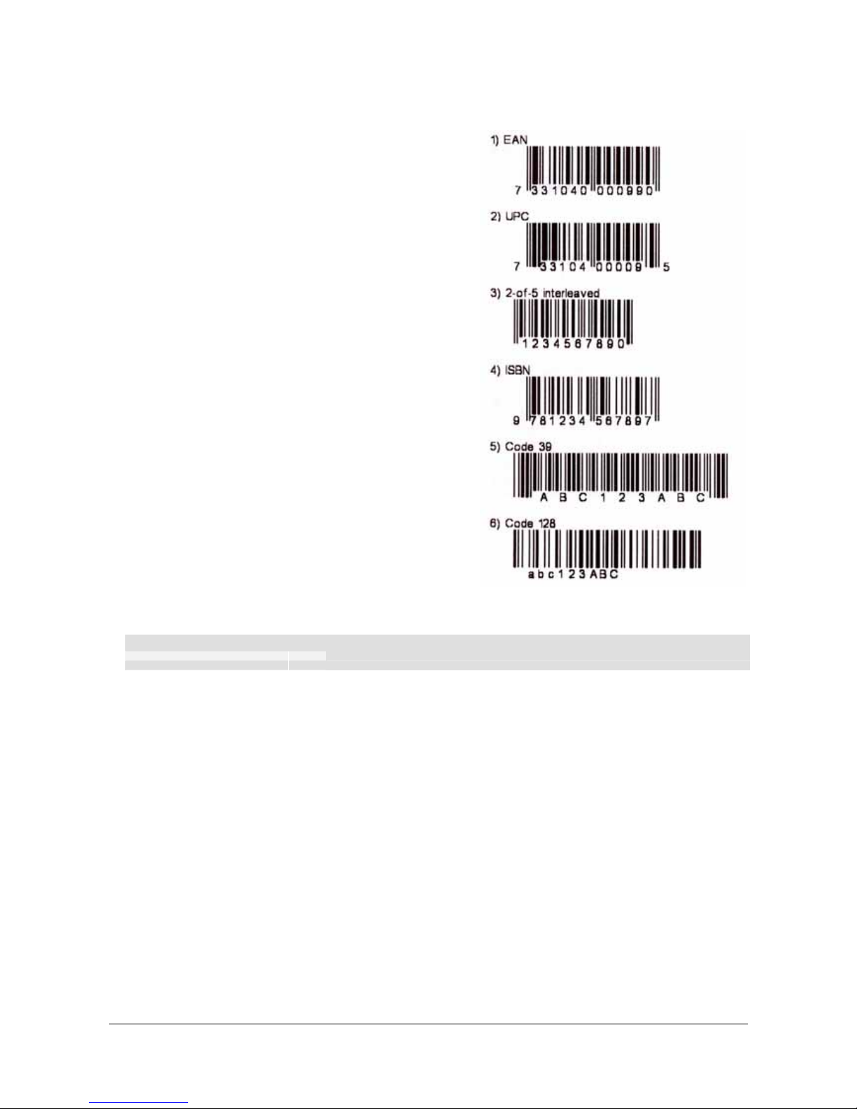
5.3.3 Barcode Commands
TTP 2000 can print EAN 8, EAN 13,
UPC, 2-of-5 Interleaved, ISBN, Code39,
Code128, and EAN128 barcodes.
Example:
<ESC>BS<00h><00h><78h><00h>
<00h><0Ch><00h><50h><00h><02h>
<00h>
<ESC>BW<00h>733104000099<00h>
<RS>
The above will print an EAN barcode with
height = 10 mm, 15 mm in from the right
margin.
CODE 128 / EAN128
The following codes select function codes
in Code 128:
Name Dec Hex
FNC1 193 C1h
FNC2 194 C2h
FNC3 195 C3h
FNC4 196 C4h
Figure 25. Samples of barcodes .
Starting the data string starts with
FNC1
generates an EAN128 code.
ESC B S n1...n11
1B 42 53 n1...n11 hex
27 66 83 n1...n11 decimal
Barcode field Specify
Bar codes can only be printed in portrait mode unless Fixed Document Mode is selected
with parameter n36.
The command reserves an information field as a bar code field. The command also
identifies the type, number of digits, and the configuration of bars to be placed in the bar
code field.
n1 Specifies the bar code field No. (0—15). Bar code fields may be specified in any
order.
n2n3 Sets the X coordinate of the bar code field origin (n2 is the higher-order and n3
the lower-order byte).
n2 and n3 must be 1-byte hexadecimal or decimal numbers. The values must not
place the bar code outside the total pixel count that can be handled by the printer.
n4n5 Must be specified but the values are discarded by the printer.
n6 Specifies the number of bar code digits, but is ignored by the printer.
n7n8 Specifies the height of the bars.
n9 Specifies the type of bar code. The following types are supported.
n9 = 0 EAN 8 or 13 (auto detect). The printer calculates the necessary check digit.
Page 36

Programming
0602 TTP 2000 Kiosk Printer–Technical Manual 35
n9 = 1 UPC
b9 = 2 2/5 Interleaved (even number of characters must be sent)
n9 = 3 ISBN
n9 = 4 Code128 (Start data string with C2h to encode EAN128)
n9 = 6 Code39
n10 Specifies the thickness of the narrow bar 0=1 pixel, 1=2 pixel, and so on.
n11 Specifies the wide-bar-to-narrow-bar ratio. Only used in Code 39 and 2-of-5
interleaved where different ratios are allowed
ESC BW n1nx
1B 42 57 n1 nx Hex
027 066 087 n1 nx Decim al
Barcode Write
Writes data to the bar code field reserved by the ESC BS command.
n1 Specifies the field No. Range 0 to 15. Fields can be specified in any order
but other values than 0 to 15 are ignored.
n2 . . . nx Specifies bar code data bytes.
To create a bar code add-on, insert a space character and then the data for
the add-on. Two of five characters are allowed of the add-on.
NUL must be placed at the end of the bar code data.
Any invalid bar code character terminates the command, and print <Invalid barcode> on
the printout.
5.3.4 Example:
<ESC>BS<h00><h00><h32><h00><h00><h0C><h00><h50><h00><h02><h00>«»
<ESC>BW<h00>733104000099<h00>«»
<RS>«»
Will print one barcode with height = 10 mm and moved 10 mm to the right
ESC B C
1B 42 43 n1 hex
27 66 67 n1 decimal
Barcode Clear
Clears the bar code field reserved by command ESC BS.
n Specifies which bar code field to clear. The range is 0 to 15. The fields may be
cleared in any order.
Page 37

Programming
36 TTP 2000 Kiosk Printer–Technical Manual 0602
5.3.5 Graphics commands
ESC b n1...n5 data
1B 62 n1...n5 Data hex
27 98 n1...n5 Data decimal
Print Bitmap at XY-position
Prints a black & white (1-bit color depth) Windows bitmap (BMP-file) at the specified X-Y
position. The bit-map must be a complete uncompressed Windows bitmap where the data
starts with BM. Max size is limited to the free RAM printed on the self-test printout.
n1 Always 0
n2n3 Two byte definition of the X print position (in pixels).
n4n5 Two byte definition of the Y print position (in pixels).
data Bitmap data.
After the bitmap has been printed, the cursor will return to the X-position that it had before
the bitmap command was issued.
Selecting horizontal mode (with
ESC o 0h
) prints the image in portrait orientation, while
selecting the vertical mode (with
ESC o 1h
) prints the image in landscape orientation.
NOTE! — The Y print-position and horizontal/vertical orientation only works if Fixed
Document Mode is set with parameter n36.
ESC s n1 data
1B 73 n1 Data Hex
27 115 n1 Data Decimal
Send dot-line, 203 dpi
Sends one line of dot data. This command is used to build images, one dot line at a time
by the printer driver and should not be combined with text commands.
n Determines the number of bytes. Range: 1-255.
<data> 1 – x bytes, where x is the printhead width in bytes. The printhead width is in
the spec. of the printer.
For example:
•
58 mm printers use 54 bytes
•
80 mm printers use 72 bytes
CAUTION! – Always send the No. of bytes that you specify!
If more than the specified No. of bytes are received, the rest of the bytes
will be interpreted as text or commands. This can cause any kind of
problems in the printer as graphics data can contain any hex value.
If you specify less data then the actual printhead width, the printer will fill
the rest of the dot line with spaces.
Page 38
Programming
0602 TTP 2000 Kiosk Printer–Technical Manual 37
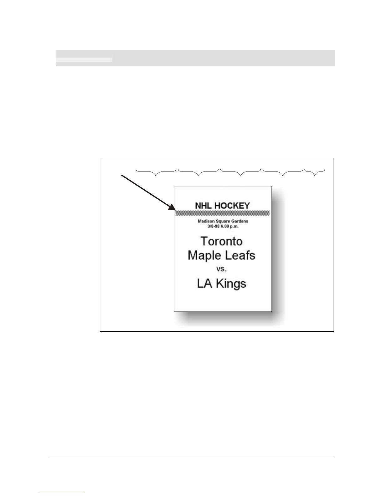
ESC r n1...n9
1B 72 n1...n9 hex
27 114 n1...n9 decimal
Print Ruler Line
Prints a ruler line across the paper.
A ruler line is normally used to divide the printout into logical parts to make it easier to
read. A ruler line is actually an area defined by a start X-Y position and a stop X-Y
position. This area is filled with black or a checkered pattern.
n1n2 Two byte definition of the X start position
n3n4 Two byte definition of the Y start position
n5n6 Two byte definition of the X stop position (must be larger than x1x2)
n7n9 Two byte definition of the Y stop position (must be larger than y1y2)
n9 Fill pattern, 0=black, 3= Checkered
<ESC>r<000><000><000><000><001><193><000><024><003>
X start Y start
X stop Y stop
Fill
0=black
3=checkered
SW99006
Figure 26 Printout with checkered ruler line
Page 39

Programming
38 TTP 2000 Kiosk Printer–Technical Manual 0602
ESC g n1...n5
1B 67 n1...n5 hex
27 103 n1...n5 decimal
Print Logotype
Prints a customized logotype1 stored in the flash PROM. See also “Logotypes” on page 56.
n1 One-byte logotype identification No. (0—15)
n2n3 Two-byte definition of desired print position in X-direction measured from lefthand edge of the page (see page 69 regarding definition of ”page”). X-direction is
perpendicular to the paper transport direction.
ESC L n1
1B 4C n1 Hex
27 76 n1 Decimal
Print Logotype at Current Position
Prints a customized logotype stored in the flash PROM at the position of the cursor. The
bottom line of the logotype is positioned at the baseline of the text on the line. If the
logotype is higher than the text, the line spacing is increased.
See also Logotypes on page 56.
n One-byte logotype identification No. (0—15)
1
For logotype loading, see "ESC & 1" on page 43.
Page 40

Programming
0602 TTP 2000 Kiosk Printer–Technical Manual 39
5.3.6 Print commands
ESC p
1B 70 Hex
27 112 Decimal
Print
This command makes the printer print the contents of the line buffer.
Text is converted from text to pixel lines and stored in the line buffer when an LF is
received. If the line buffer is empty when ESC p is received, nothing is printed.
Text to be printed <LF><ESC>p
prints "Text to be printed" on the paper.
Printout is effected automatically at:
Cut (
RS
and
ESC RS
)
Form feed (
FF
)
Clear presenter (
ENQ
)
Run presenter (
ESC FF n
)
Print buffer full
Press on FF-button
ESC P n1
1B 50 n1 Hex
27 80 n1 decimal
Print Self-test Printout
This command makes the printer generate a self-test page based on the current
parameter settings and print that page. The parameter values printed are the ones
currently being used. They can differ from Power-ON default values if for example a
printout from Windows has been done before
ESC P
is sent to the printer. To make a self
test printout with the Power-ON default settings, power up the printer with the FF button
pressed.
n = 0 Gives standard self-test printout.
n = 1 Gives a character set printout using the font selected by parameter p14.
ESC J n1
1B 4A n1 hex
27 74 n1 decimal
Paper Advance
The value n represents the number of dot lines the paper is to be transported forwards.
Range: 1–255.
A dot line is 0.125 mm, and 255 dot lines equal approximately 32 mm.
ESC j n1
1B 6A n1 hex
27 106 n1 decimal
Paper Reverse
The value n represents the number of dot lines the paper is to be transported backwards.
Range: 1–255.
CAUTION! – NEVER reverse more than 6 mm at top of page!
You may lose grip of the paper.
A dot line is 0.125 mm, and 255 dot lines equal approximately 32 mm.
Page 41

Programming
40 TTP 2000 Kiosk Printer–Technical Manual 0602
5.3.7 Cut and present commands
NOTE! – The printer does not receive data while cut and present commands are
executed.
RS
1E Hex
30 Decimal
Cut and Eject
Effects a paper cut-off and an eject through the presenter module. The RS command automatically give the eject length of 50 mm in addition to the factor stored in parameter p47.
If the printout length is too short, paper-feed is added until the minimum printout length
(set by parameters 37 and 38) is reached, before execution of the Cut command.
NOTE! – The cut position is 9 mm before the print line. This makes the last 2 lines on a
page end up in the beginning of the next page. To get the cut after the text,
Please have parameter 49 set to auto (default setting).
If you do not use the auto setting you can use <RS> together with the paper
advance command:
<ESC>J<110><RS>
Gives a cut & eject after
the last text line.
ESC RS
1B 1E Hex
27 30 Decimal
Cut only, no Eject
Effects paper cut-off only.
Eject can be effected with the
ESC FF n
command (see 41).
To avoid thin strips of paper in the printer, multiple cut commands without paper feed inbetween will not be performed. If the printout length is too short, paper-feed is added until
the minimum printout length is reached, before execution of the cut command.
See Also Note on cut position for the
<RS>
command above.
NOTE 1! – Use the cut command if you want full control over the printer from your
system. But remember that you also must add commands to feed to the
correct cut position and eject the paper so that the customer can get hold of
it.
NOTE 2! – Top margin settings that move the paper count as paper feed
US
1F hex
031 decimal
Partial cut (unit separate)
Prints a dotted line, a pair of scissors, and partially cuts the paper to make it easier to tear
off the paper (a cut of about 5-mm in each edge).
Page 42
Programming
0602 TTP 2000 Kiosk Printer–Technical Manual 41
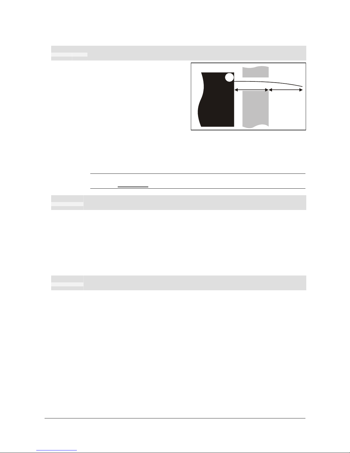
ESC FF n1
1B 0C n1 hex
27 12 n1 decimal
Eject (run presenter)
ESC FF
ejects the document through
the presenter module. Variable
n
represents the eject-length in steps.
The setting of parameter n47 is always
added to the eject n in all forms of
eject.
The range for n is 1 to 127. The range
128-255 is reserved for future use.
One step is 1 mm
Place this command after a cut command (
ESC RS
) to partially eject the printout to the
customer. Set the eject length so that the customer sees that the printout comes out of
the kiosk wall. The pull-detector gives motorized eject of the rest of the printout when the
customer pulls the paper.
NOTE! – The cut and eject command RS, automatically give the eject length of 50 mm
in addition to the factor stored in parameter n47.
EM n1
19 n1 Hex
25 n1 Decimal
Enforced Clear Presenter
Same function as
ENQ
but overrides the Retract and Retain parameter (p45) with another
presenter behavior. The function of n can be 0 to 255 0-99 ejects while 100-255 retracts
(see the description of parameter 45). The command will clear the presenter immediately
(with printing synchronization).
<EM><000>
Ejects the presented page
<EM><100>
Retracts the presented page
ENQ
05 Hex
5 Decimal
Clear Presenter
Clear the paper-path in the presenter of printouts. For example, to eject a document not
removed during the previous print/cut/eject operation. Parameter No. 45 controls how the
presenter is cleared.
Kiosk
wall
n47
Eject n
Printer
Page 43

Programming
42 TTP 2000 Kiosk Printer–Technical Manual 0602
ESC f n1
1B 66 n1 Hex
27 102 n1 decimal
Presenter loop ON/OFF/max length
NOTE! – Obsolete command, may disappear from future
program releases. Use parameter p9 instead.
n is the loop length limit in 3.2 cm steps. If the printout length exceeds the max loop limit,
it is partially ejected before the printer continues.
range 0 and 3 to 255.
n = 0 The paper is fed straight through the presenter.
n = 18 Default setting which gives a loop of just above 0.5 m.
NOTE 1! – The loop is limited to the value set by
ESC f n
to avoid paper jam. When
the set length has been looped, the printer presents that part of the printout.
Then, without cutting the paper, it continues to print the rest of the printout.
NOTE 2! – The loop is automatically disabled in vertical mode
Page 44

Programming
0602 TTP 2000 Kiosk Printer–Technical Manual 43
5.3.8 System related commands
ESC ?
1B 3F Hex
27 63 Decimal
Reset (full)
Restarts the printer with a complete reset.
This is the same as power off/on and takes about a second to execute.
ESC @
1B 40 Hex
27 64 Decimal
Reset (initialize)
Terminates the processing and initializes the control board. The control board is reset to
default-values (same as after power ON). Do not use this command as part of a print data
command string.
ESC & 001
1B 26 01 Hex
27 38 1 decimal
Load Logotype
Stores a logotype bitmap in the flash PROM. The logotype is printed with the
ESC g
and
ESC L
commands, see page 38. Also see Logotypes on page 56.
NOTE! — If the logo width exceeds the print width, the operation is aborted.
ESC & L
1B 26 4C Hex
27 38 76 decimal
Erase all Logotypes
Erases all logotypes stored in the flash PROM.
NOTE! — This command is only executed if at least one logotype has been loaded
ESC & 004
1B 26 04 Hex
27 38 4 decimal
Store current Parameter Values
Stores the current setting of all parameter values in the setting memory. These
parameters are then used as default parameters. Storing takes approximately 4 seconds.
The printer activates the presenter motor temporarily to indicate that storing is complete.
Page 45

Programming
44 TTP 2000 Kiosk Printer–Technical Manual 0602
ESC & 000
1B 26 00 hex
27 38 0 decimal
Load Font
This command is used to load a font to the printer flash PROM. The font is placed in the
first free address position in the order of load sequence.
A Swecoin font-file consists of a header containing data describing the font as well as
data for each individual character in the font.
Fonts can be designed with the font editor and loaded or deleted with the software
available for free on the Swecoin web site. The font loading and deleting commands
described here should only be used if you do not work in the Windows environment.
For complete specification of the font format, see the Fonts section of www.swecoin.se
.
NOTE! – The available font memory is printed on the self-test printout. A maximum of 8
fonts can be addressed. Exceeding any of these limits will cause this command
to fail.
ESC & C
1B 26 43 Hex
27 38 67 decimal
Erase all Fonts
Erases all fonts stored in the flash PROM.
NOTE! — This command is only executed if at least one font has been loaded
ESC & D
1B 26 44 Hex
27 38 68 decimal
Erase Fonts 4 to 7
Erases fonts number 4–7. Fonts 0–3 are not affected by this command.
The operation is complete when the printer resets automatically and activates the
presenter motor temporarily. Takes approximately 4 seconds.
ESC & F
1B 26 46 hex
27 38 70 decimal
Recall Parameter Profile
This command resets the parameters of the printer to default or any previously stored
setup.
Temporarily sets all parameters to predefined values that are stored in the printer. To
keep the values as default, store them in the flash PROM with command
ESC & 4
.
Unless you save the parameters, a reset command or power OFF/ON will return the
parameters to the settings stored in the flash PROM.
Page 46

Programming
0602 TTP 2000 Kiosk Printer–Technical Manual 45
ESC & P n1...n2
1B 26 50 n1...n2 hex
27 38 80 n1...n2 decimal
Set Parameter Value
A number of bytes in the flash PROM hold various parameter values called
default
parameters
. One or several of them can be overridden temporarily with this command.
n1 Parameter number, range 1 -255.
n2 Parameter value.
See “Default parameter settings” on page 27.
The permanently stored parameters will be used again after a printer-reset command or
at power ON.
The temporary values can, however, be stored in the flash PROM as permanent values
with command
ESC & 4
.
SET SEVERAL PARAMETERS AT ONCE
ESC & P <000> <FromPar><ParCount><Data>
FromPar is the parameter number to start writing and ParCount is the number of bytes
being sent. For every byte sent the parameter number is incremented.
Example:
<ESC>&P<000><015><005><005><010><015><020><025>«»
Sets the first 5 tabs to 5, 10, 15, 20, and 25. (FromPar 15, ParCount 5)
ESC NUL
1B 00 Hex
27 0 Decimal
Load Firmware
This command should be used when you integrate firmware loading into your kiosk
program.
NOTE! – Utility programs to load firmware into the printer
are available from www.swecoin.se
Page 47

Programming
46 TTP 2000 Kiosk Printer–Technical Manual 0602
5.3.9 Status reporting commands
See also “
Status reporting
” on page 58.
NOTE! – All status commands except for the acknowledge
marker are immediate. That is they pass the print
queue and are answered directly.
Status-codes are reset:
1 When the conditions causing them are removed.
2 When the printer is turned off/on or a reset command is received.
3 When the printhead is lifted and then lowered.
ESC ENQ 001
1B 05 01 Hex
27 5 1 decimal
Status Enquiry
A status enquiry results in response
ACK
(06h) if all sensors are clear, but
NAK
(15h) +
code if one or more sensors report some condition.
Status code Meaning
ACK OK (printer is operable)
NAK 01h Paper left in presenter module. Attempt to clear the paper path failed.
NAK 02h Cutter jammed
NAK 03h Out of paper
NAK 04h Printhead lifted
NAK 05h Paper-feed error. No paper detected in presenter although 10 cm has been
printed. Paper might be wound around the platen or, in some way, has been
forced above the presenter module.
NAK 06h Temperature error. The printhead temperature has exceeded the 60 °C
maximum limit.
NAK 07h Presenter not running
NAK 08h Paper jam during retract
NAK 0Ah Black mark not found
NAK 0Bh Black mark calibration error
NAK 0Ch Index error
NAK 0Dh Checksum error
NAK 0Eh Wrong firmware type or target for firmware loading
NAK 0Fh Firmware cannot start because no firmware is loaded or firmware checksum
is wrong.
NAK 10h Retract function timed out. If the customer doesn’t take the paper and the
printer clears the presenter due to a timeout, the pending error bit is set and
error code NAK 10h is reported.
NAK 11h Paused (ex. To avoid overheating of stepper motors)
NAK FFh Undefined error
Table 4. Status codes
NOTE! — Errors 02h, 05h, and FFh are terminal faults that require you to reset the
printer before it will be operable again. A reset means that any data in the
buffer is lost.
The printer automatically recovers from the other conditions as soon as the
condition is corrected, without data loss.
Page 48

Programming
0602 TTP 2000 Kiosk Printer–Technical Manual 47
A status enquiry command can only return one status code at a time. If there are two or
more simultaneous conditions, each condition should be cleared and the status enquiry
repeated in order to get a complete report of all status codes.
The host computer cannot be certain that all conditions have been cleared until an
ACK
is
received.
The possible conditions are reported in the above order.
NOTE! – If you want to read out all status information directly, use
ESC ENQ E
.
ESC ENQ 002
1B 05 02 hex
27 5 2 decimal
Paper-near-end Enquiry
This command requests a paper-near-end sensor (paper low) status from the printer in a
1-byte format.
Value = (01h) indicates ”No paper”
Value = (00h) indicates ”Paper present” at the sensor position
NOTE! – The status of the sensor is sampled every time the printout is cut. If three
succeeding samples show "no paper", the status reply changes to 00. This
is to prevent false alarm if the side of the paper roll is not clean. If you want
the momentary status of the sensor, use
ESC ENQ 6
and extract the paper-
near-end bit.
ESC ENQ 004
1B 05 04 hex
27 5 4 decimal
Fonts and Logotype Enquiry
Requests multiple bytes of information regarding loaded fonts and logotypes.
EXAMPLE (↵ = CR LF)
Send→
ESC ENQ 04d
Read
←
0:7862 ATM9↵
1: ↵
2: ↵
3: ↵
4: ↵
5: ↵
6: ↵
7: ↵
Free font memory:123082↵
00:38 117 Swecoin Logo ↵
01: ↵
02: ↵
03: ↵
04: ↵
05: ↵
06: ↵
07: ↵
08: ↵
09: ↵
10: ↵
11: ↵
12: ↵
13: ↵
14: ↵
15: ↵
16: ↵
Free logo memory:126352↵
Page 49
Programming
48 TTP 2000 Kiosk Printer–Technical Manual 0602
ESC ENQ 005
1B 05 05 hex
27 5 5 decimal
Sensor Enquiry
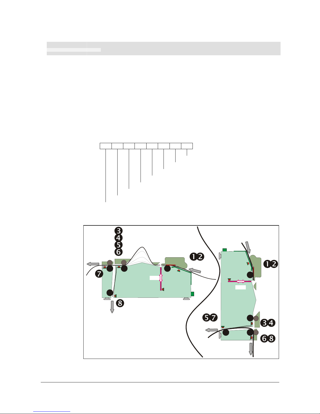
Results in a 2-byte response, reflecting the status of all virtual sensors. Virtual sensors
maintain their functionality in all configurations of this printer, while physical sensors
reported by ESC ENQ 6 signals differently depending on if for example horizontal or
vertical mode is enabled.
The same physical sensor give several virtual statuses depending on when, in the print
cycle, the sensor is activated.
FIRST BYTE:
Reserved for future use.
SECOND BYTE:
7 6 5 4 3 2 1 0 Bit
Sensor 1, Paper before head
Sensor 2, Black mark
Sensor 3, Paper after head
Sensor 4, loop ready
Sensor 5, presenter
Sensor 6, retract ready
Sensor 7, in retract
Sensor 8, at bin
Printout exit
Paper entry
Cutter
ٛ
ٛ
ٛ
Retract exit
Retract exit
Paper entry
Cutter
ٛ
ٛ
ٛ
Printout exit
ٛ
ٛ
Horizontal
Vertical
Figure 27. Physical-to-virtual sensor mapping
Page 50
Programming
0602 TTP 2000 Kiosk Printer–Technical Manual 49
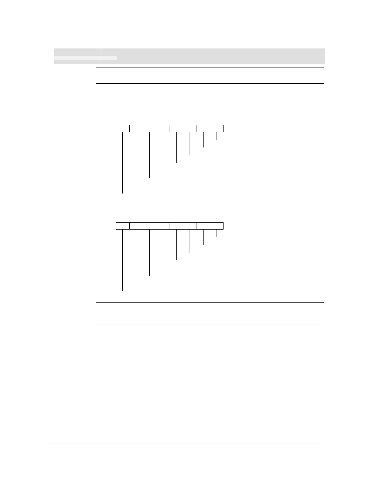
ESC ENQ 006
1B 05 06 hex
27 5 6 decimal
Status Report
NOTE! – The sensor status reported it the status report are for compatibility with older
printers. Please use ESC ENQ 5 in new applications.
Results in a 2-byte response, reflecting the status of each sensor. This command is
intended as a go/no go indication.
FIRST BYTE:
7 6 5 4 3 2 1 0 Bit
Do not use!
-
Do not use!
Error blackmark
-
Power has been OFF***
Print data exists**
Status code available*
SECOND BYTE:
7 6 5 4 3 2 1 0 Bit
Out of paper
Paper-near-end****
-
Paper at presenter
Cutter stuck
Printhead lifted
-
Retract unit mounted
HINT! – Mask away the undefined bits in your application program to avoid having to
change the application, if future firmware releases starts using them.
Mask first reply byte with E8h, Mask second reply byte with BBh
Table 5. Sensor status
* This bit indicates that a status code is available. Use
ESC ENQ 1
or
ESC ENQ E
to
fetch it.
** This bit tells you that there are data in the printer that have not yet been printed.
There are two possible reasons for that:
1) The last command received by the printer was not a command that triggers a
printout.
2) The printer is printing
*** When parallel cable is connected, both printer and host computer must have
been off to set this bit. This is because the interface powers the RAM in the
printer.
**** This paper-near-end bit differs from the
ESC ENQ 2
response, see page 47.
Bit 4 and 5 in the first byte are reset when read.
Page 51

Programming
50 TTP 2000 Kiosk Printer–Technical Manual 0602
ESC ENQ 007
1B 05 07 Hex
27 5 7 decimal
Firmware-version Enquiry
Results in a 2-byte response representing the version of the installed firmware.
The first byte represents major versions, and the second byte minor versions.
If no firmware is loaded, the printer will answer with
00h
.
EXAMPLE
Send→
ESC ENQ 07d
Read
←
<02h><29h>
That is, a response with the value
<02h><29h>
indicates version 2.41.
ESC ENQ 009
1B 05 09 hex
27 5 9 decimal
Serial-number Enquiry
Results in an 6-byte response representing the serial number.
EXAMPLE
Send→
ESC ENQ 09d
Read
←
00h 00h 02h 2Bh C6h 28h
(hex), or
000 000 002 043 198 040
(dec)
ESC ENQ 010
1B 05 0A hex
27 5 10 decimal
Control board revision Enquiry
Results in a 1-byte response representing the control board revision. A minus sign
indicates that no revision has been made, while A indicates the first revision, and so on.
EXAMPLE
Send→
ESC ENQ 10d
Read
←
n
Where n can be ‘A’ (ASCII) or41h (hex) or 065 (dec)
ESC ENQ 011
1B 05 0B hex
27 5 11 decimal
Head temperature Enquiry
Results in a 1-byte response representing the temperature of the Printhead.
EXAMPLE
Send→
ESC ENQ 11d
Read
←
n
Where n is a value representing the approximate temperature in Celsius.
The answer is an signed byte (two's complement). If bit7 is 1 than it’s a
negative value, invert all bits and add 1 the get the value.
Page 52

Programming
0602 TTP 2000 Kiosk Printer–Technical Manual 51
ESC ENQ 012
1B 05 0C hex
27 5 12 decimal
Bootware version Enquiry
Results in a 2-byte response representing the version of the installed bootware.
The first byte represents major versions, and the second byte minor versions.
EXAMPLE
Send→
ESC ENQ 12d
Read
←
<001><030>
That is, a response with the value
<01h><30h>
indicates version 1.48.
ESC ENQ c
1B 05 63 hex
27 5 99 decimal
Device ID Enquiry
Results in a string containing the device ID in the Windows Plug and Play string format.
The two first bytes represent the string length.
EXAMPLE
Send→
ESC ENQ 99d
Read
←
00d 106d
This indicates that the string is 104 characters (plus two
characters indicating the string length)
Page 53
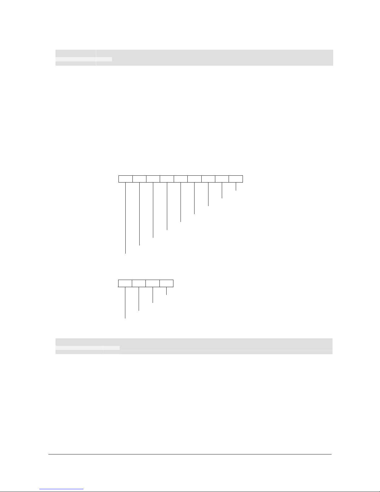
Programming
52 TTP 2000 Kiosk Printer–Technical Manual 0602
ESC ENQ E
1B 05 45 hex
27 5 69 decimal
Read extended status
Extended status is status from the printer together with devices connected to the I2C
options-bus available in some Swecoin printers (the TTP 2000 series does not have any
I
2
C bus so these parts of the command are superfluous). The short message protocol
gives replies up to 255 bytes. Other protocols may be defined in the future. Protocols are
described in separate documents.
ESC ENQ E results in a variable length reply:
n1 Protocol version, 11h = Short Message Protocol
n2 Protocol length in bytes
n3-n255 Data specified by the protocol
SHORT MESSAGE STATUS EXAMPLES
Example 1
– Out of paper presenter Jam, and shutter open error.
11 07 01 05 20 83 87 21 81 Hex
Status code 1 (shutter device)
Device Shutter
Status code 7 (printer device)
Status code 3 (printer device)
Device local host (printer)
Tag message length (bytes)
Tag ID: Status messages
Protocol Length in bytes
Protocol SM, version 1 (short message)
Example 2
– No errors in any device.
11 02 01 00 Hex
Tag message length (bytes)
Tag ID: Status messages
Protocol Length in bytes
Protocol SM, version 1 (short message)
ESC ENQ P n1
1B 05 50 n1 Hex
27 5 80 n1 Decimal
Parameter-setting data Enquiry
This command requests information about the setting of parameter n1, that is, the
parameter value stored in flash PROM or any parameter value temporarily set by other
ESC commands.
n1= 1 gives the setting of parameter 1, etc.
The parameter names are listed on page 61.
n1 = 0 gives a response where the first two bytes specifies the length of data to come,
and then follows a block of data for all parameters in the temporary setup.
Page 54

Programming
0602 TTP 2000 Kiosk Printer–Technical Manual 53
ESC ACK n1
1B 06 n1 hex
27 6 n1 decimal
Acknowledge Marker
n1 = One-byte marker. Range 1h to 255h
The "acknowledge marker" n is placed in the command queue and when the execution of
commands reaches the marker it is sent back to the host computer. This is an addition to
the status commands that pass the queue and are answered immediately when received.
EXAMPLE:
"Print data"
<LF><esc>p<ESC><ACK><01h>
Wait for <01h>
<RS><ESC><ACK><02h>
Wait for <02h>
The printer will send
<01h>
when <print data> has executed and
<02h>
when the ejecting
has been performed.
NOTE 1! — You must wait for the acknowledge marker to return before sending any
more data to the printer.
NOTE 2! — Acknowledge marker cannot be used for events that write to the flash
PROM, for instance font loading. This is because the writing procedure
erases the buffer, including the markers, and uses all RAM in the printer.
Page 55

Programming
54 TTP 2000 Kiosk Printer–Technical Manual 0602
5.4 Font loading
The printer can store 8 fonts in its flash PROM. The memory available for fonts is printed
on the self-test printout. The character size is fixed
1
, so you must load one font file for
each character size you require. The fonts are given font numbers when they are loaded
into the printer. The first font is assigned number 0 and the next font 1 etc. up to font 7.
Parameter p14 “Font Selection” will determine what font to use when no font selection
command has been received (see page 63).
You cannot erase a single font, but must erase font 4-7 with command
ESC & D,
or all
eight fonts with
ESC & C
, then reload the fonts you wanted to keep.
Windows software for font generation and management is available on the Swecoin web
site. If you need to load fonts in a non-Windows environment, use the
ESC & NUL
command.
The time required for processing the font data that is loaded is typically 15–20 seconds
per font, excluding transfer time. During this time, any data sent to the printer will be lost.
NOTE! — The font processing ends with a reset. The presenter motor runs momentarily
to indicate that the printer is ready to be used.
CAUTION! — Loading to the flash PROM will erase the RAM completely since the
RAM is used during the loading process. Any print data residing in RAM
will thus be lost.
5.4.1 File format
A font consists of a header describing the font, then data for every character in the font.
The header has to be downloaded even if the font consists of a single character only.
Below is a description of the font header.
1 byte Reserved Should always be 0 (zero)
1 byte Reserved Should always be 0 (zero)
1 byte Char. width (X) The number of bytes required for the width of one character,
usually 2 or 3. Range 1 to 8.
1 byte Character pitch The maximum width of one character in the set. This value is
used for tab position calculation. Range 1 to 255.
1 byte Char. height (Y) The maximum height of one character matrix measured in
pixels. This is also the minimum line spacing for this
character set.
27 byte Font name String of characters used to identify the character set.
This will be printed on status printouts. (E.g. Swiss 10 cpi.)
Char_matrix table: 256 records, each containing 3 bytes.
3 byte Char_width (pixels) + Char_Ystart(pixels) + Char_Yheight(pixels)
Char_bitmap data: Bitmap data for all characters that are to be defined.
1
Multiple height and width commands can be used on all fonts.
Page 56
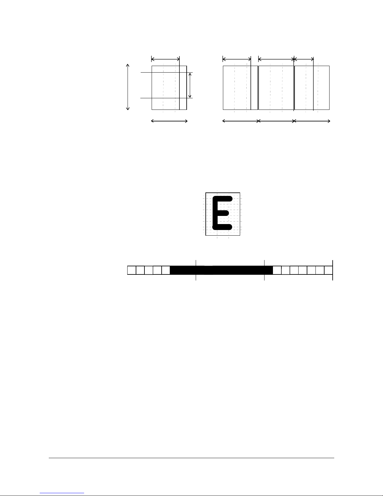
Programming
0602 TTP 2000 Kiosk Printer–Technical Manual 55
A
Char_Ystart
Baseline
Char_sizeX
Char_Yheight
Char_sizeY
Char_width
A
Char_pitch
Char_width
W
Char_pitch
Char_width
g
Char_pitch
Char_width
Character bitmap data:
A character is made up of a bitmap the size of which is:
Char. width (X) * Char. Height (Y) bytes.
012
0
4
ROW
COLUMN
Col 0 Col 1
MSB LSB MSB LSB
Col 2
MSB LSB
Row 1
=03H =FFH =80H
The bitmap data consists of bitmap patterns for each character in a character set for
which the parameter Char_width in the Char_matrix table is set to a value between 1 and
24. A character that has its Char_width set to zero, is not included in the bitmap data.
The bitmap for one character is then defined according to the following table:
(COL 0, ROW Ystart) , (COL 1, ROW Ystart) , (COL 2, ROW Ystart)
(COL 0, ROW Ystart+1) , (COL 1, ROW Ystart+1) , (COL 2, Ystart+1)
.
.
(COL 0, ROW Ystart+Yheight), (COL 1, ROW Ystart+Yheight ), (COL 2, ROW
Ystart+Yheight)
In this example, each row consists of 3 columns equal to 3 bytes.
In order to minimize the required storage space, only rows between Ystart and
Ystart+Yheight are included in the character bitmap.
Page 57

Programming
56 TTP 2000 Kiosk Printer–Technical Manual 0602
5.5 Logotypes
Up to 16 logotypes can be stored in the flash PROM of the printer. The logotypes can be
positioned and printed out with commands
ESC g or ESC L
.
The exact number of logotypes and their sizes is determined by the total amount of
memory used for fonts, logotypes and loaded firmware. Make a test printout to see how
much memory is available.
NOTE! – Logotype No. 0 is printed in the top of the self test printout, so this can be used
to customize the self test printout.
5.5.1 Loading
Windows software that converts black and white BMP bitmap files to logotypes and load
them into the printer is available on the Swecoin web site. If you need to load logotypes in
a non-Windows environment, use the
ESC & 1
command.
The time required by the printer to process logotype data, excluding transfer time from the
PC, is typically 15 to 20 seconds, per logotype. During this time, any data sent to the
printer will be lost.
5.5.2 File format
A header containing information about the logotype number, size and logotype name
shall define each loaded logotype. Immediately after the header follows the actual bitmap
of the logotype.
ESC & 01H <Header><Bitmap>
Header:
Byte 0 Logotype number used to identify the logotype when printing.
Byte 1 X size measured in bytes.
Byte 2 Y size measured in pixels.
Byte 3—15 A logotype name that will be printed on test printouts.
Bitmap:
The bitmap
must
have exactly (X size * Y size) number of bytes. 1=black, 0=white dot.
Bit No. 7 in byte 0 represents the top left corner of the logotype.
X size
Y size
0
7
Byte 0
Page 58

Programming
0602 TTP 2000 Kiosk Printer–Technical Manual 57
5.5.3 Printing
To print a logotype you can use two commands,
ESC L n1
, prints the logotype at the
current cursor position, just like any character.
ESC g n1 n2n3 n4n5
prints the logotype
at a specified X-Y position.
n1 One byte logotype number, (0—15)
n2n3 Two byte X position measured in pixels from the left hand edge of the print
window.
n4n5 Two byte Y position in pixels from top of the page.
These bytes must always be inserted but they are ignored in variable-pagelength mode where logotypes are always printed at the current Y-position.
5.5.4 Erasing
All logotypes are erased with the
ESC & L
command.
CAUTION! — Loading to the flash PROM will erase the RAM completely since the
RAM is used during the loading process. Any print data residing in RAM
will thus be lost.
Page 59
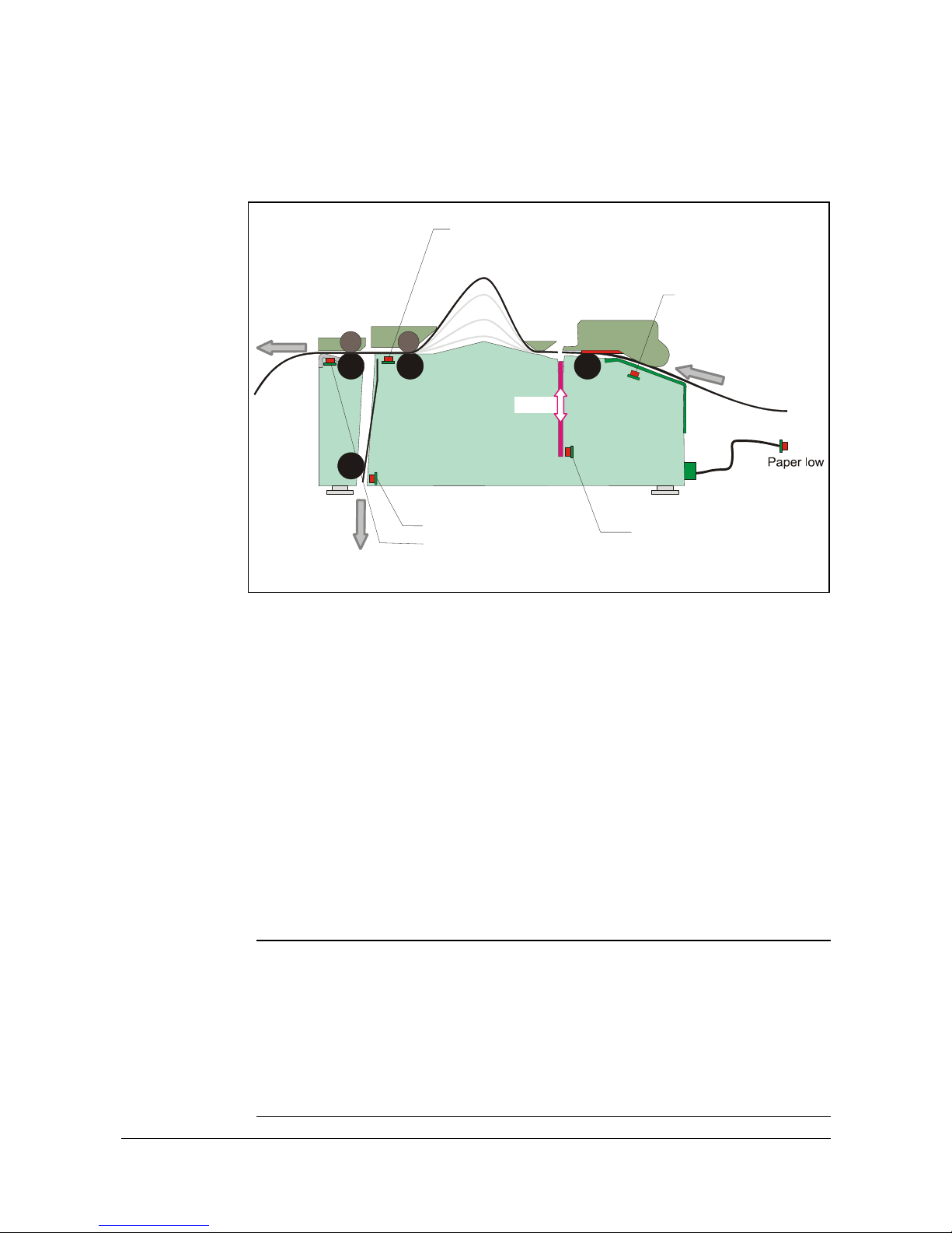
Programming
58 TTP 2000 Kiosk Printer–Technical Manual 0602
5.6 Status reporting
The printer is equipped with a number of sensors that report the printer status and various
conditions such as out-of-paper, previous printout not removed, etc.
Retract exit when horizontal
Printout exit when vertical
Paper entry
Cutter
ٛ
Printout exit when horiz.
Retract exit when vert.
ٛ
ٛ
Cutter home sensor
Paper-out/black-mark
W
aste when horizontal
Presenter
Waste when vertical
Figure 28. Sensor placement in the printer
A good practice in unattended printer applications is to check for errors and paper
availability before printing.
1. Send a Status Report Query (
ESC ENQ 6
, page 49) and check that the answer is "No
errors"
2. If “Status codes available” is indicated, read out the status message with Status
Request (
ESC ENQ 1
, page 46), and take appropriate actions.
3. Send a paper-near-end query (
ESC ENQ 2
, page 47) to see if the sensor reports low
paper level.
4. If paper-near-end is indicated, report the condition to the systems supervisor so that
he can schedule a service visit to the printer.
5. Print the printout.
NOTE 1! — A status reply must be read! Sending a second status query without
reading the reply of the first query may lock the printer.
NOTE 2! — When using a multitask OS, status queries and responses may not be
transferred immediately from your application to the printer and vice versa.
So write your program in such a way that it repeats the query if it gets a
timeout or an invalid reply. Good practice is to ask once every ten seconds,
five times before giving up.
NOTE 3! — You should construct your application in such a way so as not to request
status while printing, as this can result in loss of data
Page 60
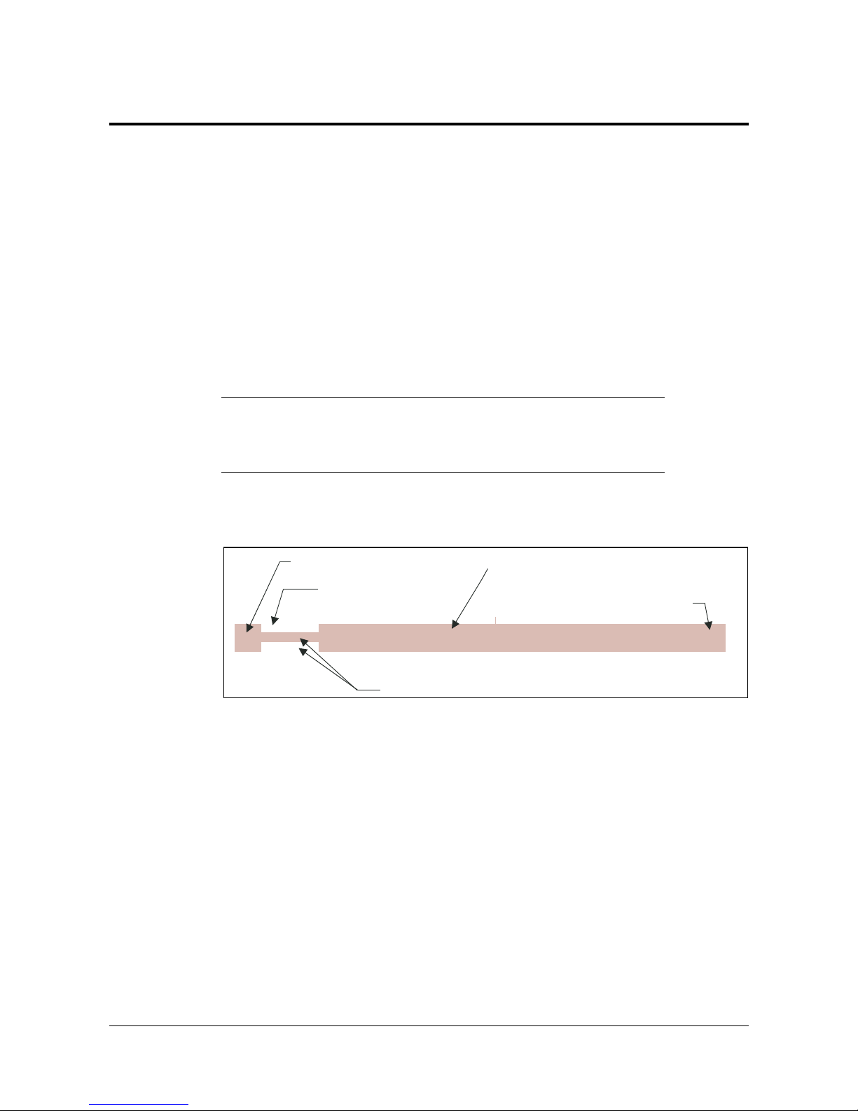
Default parameter settings
0602 TTP 2000 Kiosk Printer–Technical Manual 59
6 DEFAULT PARAMETER SETTINGS
Some of the printer settings can be stored in the flash PROM so that they will be used
also after power OFF.
The stored parameter settings are printed out on the self-test printout.
The number in front of the function is the parameter number (n) used when setting the
parameter with the command
ESC & P n v
.
You can use the parameter settings pretty much like normal commands. Either send the
parameter values with each printout, or set them up once and then send
ESC & 4h
to
store all settings in the flash PROM.
You can always return to factory default settings by sending
ESC & F 10
, and then
storing those settings with
ESC & 4h.
NOTE 1! – The parameters can be locked so that no changes are possible.
Check parameter 53 on the self-test printout to find out.
NOTE 2! – If you try to set a parameter to an invalid value, the parameter
will be set to the nearest valid value below.
6.1 How the parameters are described
0 Default
0 Min
47
255 Max
Eject calibration constant (mm)
DRV
Parameter number
Default value
Range
Description as printed on self test printout
DRV indicates that the
Windows driver overrides setting
SW 02001
6.1.1 Default value
The default values indicated are "factory default settings" you get by sending
ESC & F 10
. These are not necessarily the settings that your printer was originally
delivered with because many printers have customized settings when delivered.
6.1.2 Examples
Command examples are formatted in
Courier
and typed in the same way as used in the
Swecoin TTP editor:
<ESC>&P<001><019>
Where <ESC>
means the escape character 27 decimal (hex 1B). Numbers between less-
than and greater-than characters, for example
<001><015>
, means 1 and 15 decimal
(hex 1 and 13).
Page 61

Default parameter settings
60 TTP 2000 Kiosk Printer–Technical Manual 0602
6.2 Summary of parameter settings
TTP model
Parameter Description ESC&F Default Page 2010 2020 2030
1
Baud rate 96 (9600 Baud) 61 X
2
Data bits 8 61 X
3
Parity 0 (No parity) 61 X
4
Flow control 2 (Hardware) 61 X
5
Disable parallel port signaling 0 (No) 62 X
7
Burn time 9 74 X X X
8
Print speed 19 (150 mm/s) 62 X X X
9
Presenter loop length 15 (48 cm) 63 X X X
10
Pulse control 3 (2 burn pulses) 63 X X X
12
Font attributes 0 (off) X X X
13
Line spacing 0 (Auto) 63 X X X
14
Font selection 0 (TTP Mono 9) 63 X X X
15 to 30
Tab stop 4, 8, 12 etc. 63 X X X
33
CR/LF 0 (LF = CR/LF, CR=Ignored) 64 X X X
34
Auto cut after FF 1 (Off) 64 X X X
36
Document mode 1 (Variable) 64 X X X
37 and 38
Page length, Minimum / fixed / BM 2, 88 (75 mm) 65 X X X
39
Max black mark length 80 (10 mm) 66 X X X
40
Min black mark length 24 (3 mm) 66 X X X
41 and 42
Black mark cut offset 0, 0 (0 mm) 66 X X X
43 and 44
Black mark top margin 0, 0 (Disabled) 66 X X X
45
Trash bin mode (Retract function) 3 (Eject and retract after 30 s) 66 X X X
47
Wall compensation 0 67 X X X
49
Advance before cut 0 (Off) 67 X X X
51
Black mark level 75 67 X X X
52
Warning level 0 (Off) 67 X X X
56
Max status code 255 68 X X X
57
System 255 68 X X X
NOTE! – When the printer is set up the way you like it to be, you send
ESC & 4h
, and all settings will be stored.
Page 62

Default parameter settings
0602 TTP 2000 Kiosk Printer–Technical Manual 61
6.3 Serial interface set-up
96 Default
11 Min
1
96 Max
Baud rate
Stores the communication speed on the serial interface.
<ESC>&P<001><024>
2400 bps
<ESC>&P<001><048>
4800 bps
<ESC>&P<001><096>
9600 bps
<ESC>&P<001><019>
19200 bps
<ESC>&P<001><038>
38400 bps
<ESC>&P<001><057>
57600 bps
<ESC>&P<001><011>
115200 bps
NOTE! – If you set an invalid value, the baud rate will return to the previous value.
8 Default
7 Min
2
8 Max
Data bits
Selects if 7-bit ASCII, or 8-bit, is used on the serial interface.
<ESC>&P<002><007>
7-bits (characters 0-127)
<ESC>&P<002><008>
8-bits (characters 0-255)
0 Default
0 Min
3
2 Max
Parity
Select what parity to use on the serial interface.
<ESC>&P<003><000>
No parity
<ESC>&P<003><001>
Odd parity
<ESC>&P<003><002>
Even parity
2 Default
0 Min
4
2 Max
Flow-control
Select what handshaking to use on the serial interface.
<ESC>&P<004><000>
No flow control
<ESC>&P<004><001>
Xon / Xoff 1
<ESC>&P<004><002>
Hardware
1
DO NOT USE if you send any type of binary data like graphics data, status requests etc. Xon / Xoff only works when plain text
is sent unidirectional to
the printer. Graphics and status replies may well contain the Xon (11h) and Xoff (13h) characters and
will obstruct the communication.
Page 63

Default parameter settings
62 TTP 2000 Kiosk Printer–Technical Manual 0602
6.4 Parallel port setup
0 Default
0 Min
5
1 Max
Disable parallel port signaling
Pins 12 and 15 on the parallel port signal paper out and error. However, in an
unattended kiosk you may not want this because it causes the host computer to stop
communicating, and the operating system may display a warning or error message on the
kiosk screen.
By disabling the hardware signals, the kiosk software can for example use status
commands to find out paper level and alert appropriate personnel when the level is low,
then close the kiosk when paper is out.
<ESC>&P<005><000>
No, paper out and error signals are
not
disabled
<ESC>&P<005><001>
Yes, paper out and error signals are disabled
NOTE! — When enabled, the hardware signal on pin 12 and 15 will block all
communication until the error is corrected. This means that it will be
impossible to ask for status.
6.5 Print setup
9 Default
1 Min
7
15 Max
Burn time
DRV
1
A long burn time gives darker print. On insensitive paper types you may have to increase
the burn time to get an acceptable print quality.
19 Default
1 Min
8
19 Max
Max print speed
DRV
The main reason to decrease the print speed is to enhance print quality, and to reduce
average current consumption.
n
1 2 3 4 5 6 7 8 9 10 11 12 13 14 15 16 17 18
19
mm/s
47 48 49 50 51 52 53 55 57 61 65 70 77 86 96 107 123 136
150
NOTE! — Some settings result in printer chassis resonance causing increased noise
and deteriorated print quality
1
DRV indicates that, when using Windows, the driver takes over this setting so please set appropriate value in the driver
properties/document defaults.
Page 64

Default parameter settings
0602 TTP 2000 Kiosk Printer–Technical Manual 63
15 Default
3 Min
9
255 Max
Presenter Loop length
Limits the maximum loop length. When the set length is reached, the printer ejects part of
the printout and continues too print. You use this when you have very limited space for
the loop inside the kiosk. Each step represents a 3.2-cm increment.
Setting the parameter to 0 disables the looping and feeds the paper straight out.
<ESC>&P<009><000>
Disable the loop
…
<ESC>&P<009><007>
16 cm loop
…
<ESC>&P<009><015>
48 cm loop
3 Default
3 Min
10
7 Max
Print head pulse control
Controls how the print head burns the pixels;
<ESC>&P<010><003>
2 burn pulses
<ESC>&P<010><007>
4 burn pulses
<ESC>&P<010><007>
4 burn pulses
CAUTION! – 3 and 7 are the only allowed setting, do not set anything else!
0 Default
0 Min
13
30 Max
Line spacing
The line spacing is normally set by the font height. With this parameter you can set a line
spacing that is higher that the font height. Line spacing settings lower than the font height
will be ignored.
<ESC>&P<013><030>
30 pixels or font height, whichever is the largest
0 Default
0 Min
14
7 Max
Font selection
Store which font number is used if no font is specified. Font is selected using the "Select
Font " command
ESC ! n
. Selecting an invalid font gives a software error status message
(invalid index).
- Default
1 Min
15 to 30
255 Max
Tab stop
Stores 16 different TAB stop positions. The position is set in increments of 2.5-mm.
Tab position 255 sets a tab stop on the last position of the line. Use this if you want
underline or reversed text to extend across the full paper width.
To set all tab stops at once, follow the procedure "Set several parameters at once"
described on page 45.
To move a single tab stop, use the set parameter command
<ESC>&P
. for example:
<ESC>&P<015><010>
Set the first tab stop 25 mm from the left margin.
Default positions are one TAB on each cm; that is parameter values 4, 8, 12 etc.
Page 65

Default parameter settings
64 TTP 2000 Kiosk Printer–Technical Manual 0602
0 Default
0 Min
33
4 Max
CR/LF behavior1
Carriage Return and Line Feed can be interpreted in five different ways to suit different
operating systems.
<ESC>&P<033><000>
LF = CR/LF CR = Ignored
<ESC>&P<033><001>
LF = CR/LF CR = CR
<ESC>&P<033><002>
LF = LF CR = CR
<ESC>&P<033><003>
LF = LF CR = CR/LF
<ESC>&P<033><004>
LF = Ignored CR = CR/LF
NOTE! – The character currently interpreted as LF converts
text from the input buffer to pixels on the paper. If
no such character has been received after 379
characters, a linefeed is inserted automatically.
1 Default
0 Min
34
1 Max
Auto cut after FF
Decides if the printer should cut after executing an FF command, or if it should just feed
the form length.
<ESC>&P<034><000>
No cut
<ESC>&P<034><001>
Cut
1 Default
0 Min
36
2 Max
Document mode
DRV
Determines what should control the page length:
<ESC>&P<036><000>
Fixed Document Mode. Shorter documents will automatically be
extended, while longer documents will be divided into several
pages of the desired length.
Page length will be the length set by parameters 37 and 38
<ESC>&P<036><001>
Variable Document Mode. The length of the page varies with
the contents (printouts shorter than the value specified by
parameters 37 and 38 will be extended to that length)
<ESC>&P<036><002>
Black Mark Mode. Marks on the paper set the form length.
Minimum one form length is always fed. If a black mark is found
before that, the printer feeds to the next black mark, then cuts
and ejects. This ensures that no small paper stripes are cut of
and left in the printer.
NOTE! – Max page length in Fixed Document Mode is A5-size, which is 148.5 mm.
1
v=0 is suitable for Windows, v=1 for UNIX and Mac OS X, v=2 for DOS, and v=4 for Macintosh Classic
Page 66
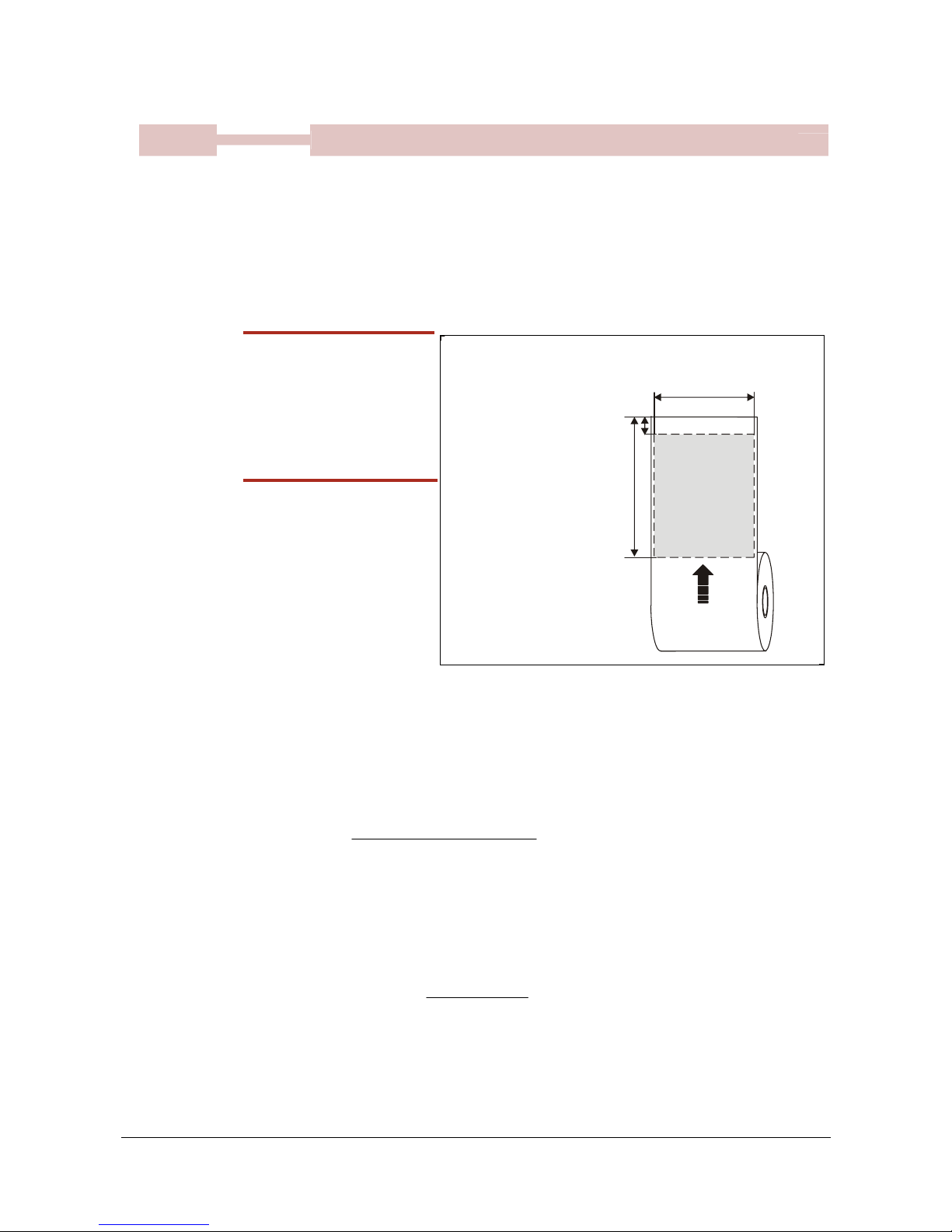
Default parameter settings
0602 TTP 2000 Kiosk Printer–Technical Manual 65
2 , 88 Default
2 , 48 Min
37 & 38
255 , 255 Max
Page length
DRV
Defines three different things:
1) The minimum length of a page in variable document mode
2) The actual page length in fixed document mode
3) The distance between black marks in black mark mode
One step is 0.125 mm. Settings shorter than 70 mm, will be interpreted as 70 mm.
<ESC>&P<037><006><ESC>&P<038><064>
Set page length to 200 mm.
Length p37 p38
70 mm <002> <048>
75 mm <002> <088>
100 mm <003> <032>
150 mm <004> <176>
200 mm <006> <064>
250 mm <007> <208>
300 mm <009> <096>
SW97063-R4
TEXT
Text text
TEXT
Text text
Page length
(minimum 93) mm
Page width =
applicable print
window width
Paper transport
direction
To p m a r g i n
(Distance between cut and print line, 12 mm)
Figure 29. Definition of page size
Fixed document mode
Max
fixed document mode
page length is depends of the amount of free ram. Make a
self-test printout to check how much is available in your printer. (Depends on firmware
version).
marginbottommargintop
widthPaper
bytesinRAMFree
lengthPage −−
−
=
1024
Paper length, top, and bottom margins are in pixel lines. Paper width is in bytes or mm.
(1 byte = 1 mm.)
Example:
If Free RAM on a TTP 2000 is 114627 bytes, print width is 80 mm = 80 bytes,
top margin is 20 mm, and bottom margin 10 mm (20 x 8 =160 and 10 x 8 = 80
pixel lines):
mmlinespixellengthPage 147118080160
80
1024114627
==−−
−
=
If a too large fixed page is specified the printout will be blank from memory full to the cut.
Page 67

Default parameter settings
66 TTP 2000 Kiosk Printer–Technical Manual 0602
50 Default
1 Min
39
160 Max
BM (black mark) length
DRV
Specifies the length of the black mark in 0.125-mm steps. Measure the length of the black
mark on your paper and enter that value here.
Marks 5 mm longer than this value are interpreted as paper out. The default value of 80
equals 10 mm.
<ESC>&P<039><040>
Sets max black mark length to 5 mm.
30 Default
1 Min
40
159 Max
Min BM (black mark) length “Garbage Filter”
DRV
Specifies the minimum length of the black mark in 0.125-mm steps. Shorter marks are
ignored. The default value of 24 equals 3 mm.
<ESC>&P<040><036>
Sets min black mark length to 4 mm.
0 , 0 Default
0 , 0 Min
41 & 42
255 , 255 Max
BM (black mark) cut offset
DRV
Defines the paper feed between the black mark detection and cut. One step is 0.125 mm.
<ESC>&P<041><001><ESC>&P<042><144>
Feeds 50 mm between black mark and cut.
0 , 0 Default
0 , 0 Min
43 & 44
255 , 255 Max
Top margin (mm)
Defines the distance between the cut in Black mark mode and the top of the first text line
in 0.125 mm steps. The top margin feed is effectuated when the presenter is cleared
from the previous page.
0 = disabled top margin. This gives the physical top margin of the printer, which is 9 mm.
Avoid settings 1 – 8 mm because then the printer must reverse the paper before starting
to print, which may cause paper jam, especially at small roll diameters.
<ESC>&P<043><000><ESC>&P<044><240>
Add 30-mm top margin.
3 Default
0 Min
45
130 Max
Trash bin mode (Retract function)
Sets the function of the "retract and retain" function.
<ESC>&P<045><000>
Eject page when new page is printed. (Retract disabled)
<ESC>&P<045><003>
Eject page when new page is printed. Page not taken after 30s
will be retracted. (Range 1-30, 1 step = 10 s)
<ESC>&P<045><100>
Retract page when new page is printed
<ESC>&P<045><103>
Retract page when new page is printed. Page not taken after
30s will be retracted. (Range 101-130, 1 step = 10 s)
Page 68
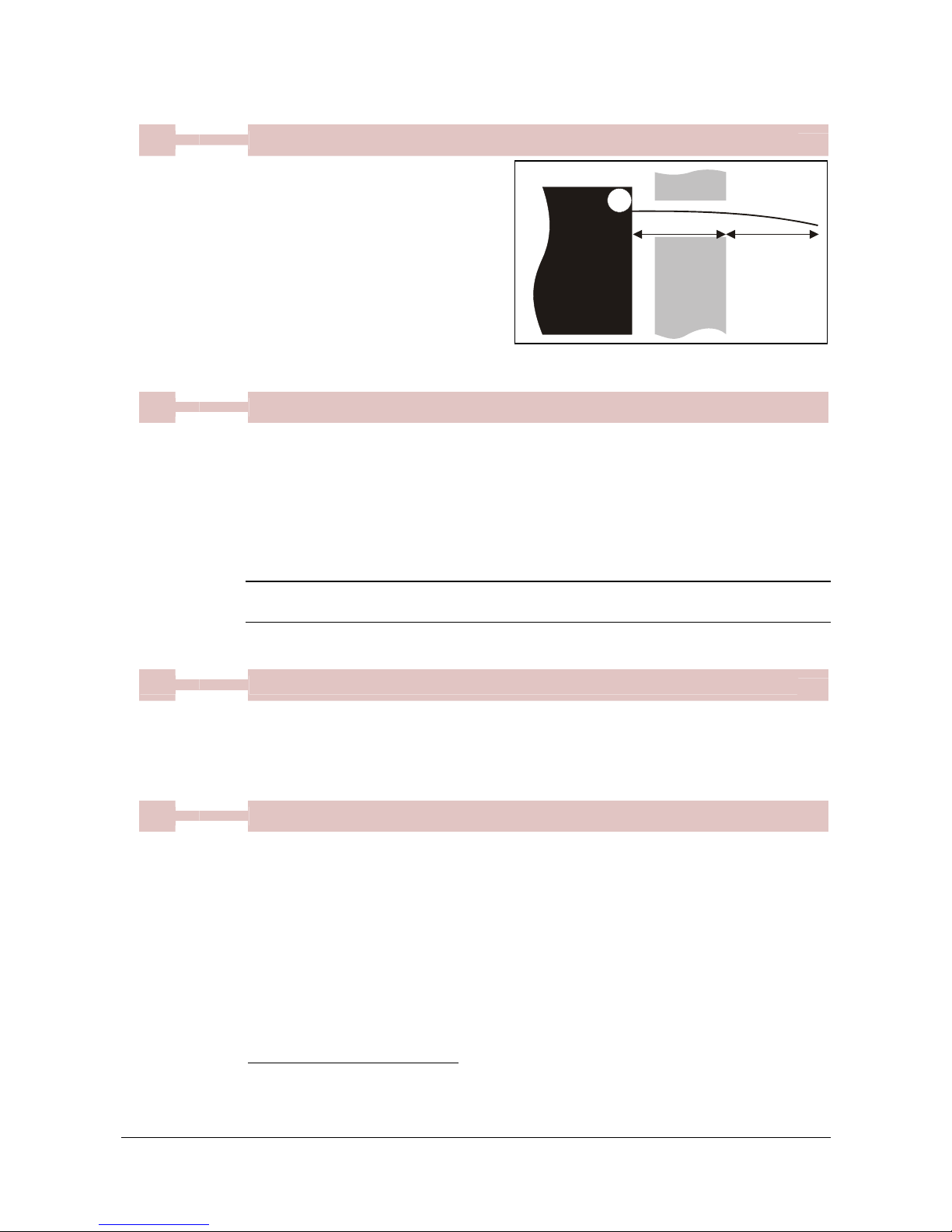
Default parameter settings
0602 TTP 2000 Kiosk Printer–Technical Manual 67
40 Default
0 Min
47
255 Max
Wall Compensation (mm)
DRV
When the printout is printed and cut,
the presenter ejects 50 mm of the
page so that the customer can grab it.
If the kiosk wall is thick, or if you just
want a longer part of the printout to be
visible, this parameter adds extra eject
length.
<ESC>&P<047><050>
Adds 50 mm
extra eject = 100 mm in total.
1 Default
0 Min
49
1 Max
Advance before cut
DRV
Selects if the cut command cuts at the position where the paper is at, or if the printer
should advance the paper before cutting.
<ESC>&P<049><000>
Off
<ESC>&P<049><001>
Automatic Distance Calculation1
Set to 1 if the printer is used in text mode and 0 if it is used from a driver that takes care
of this in the driver.
NOTE! – The paper is advanced before the FF command calculates the page length to
see if the page length is longer than the set minimum length.
50 Default
0 Min
51
255 Max
Black mark sensitivity
DRV
This parameter is used by command ESC # to store the calibration of the black mark
sensor. Normally there is no need to set this parameter manually.
0 is white and 255 is pitch black (out of paper).
0 Default
0 Min
52
255 Max
Warning level
Turns on/off indication of Paper near end level on the status indicator. This affects only
the status indicator, not the status enquiries
<ESC>&P<052><000>
No indication
<ESC>&P<052><001>
Paper Near End indication
1
"Automatic Distance Calculation" means advancing the paper with the Head-To-Cutter distance
(12 mm on the TTP 2000).
Kiosk
wall
n47
Eject n
Printer
Page 69

Default parameter settings
68 TTP 2000 Kiosk Printer–Technical Manual 0602
255 Default
0 Min
56
255 Max
Max status code
This will control the highest status code that is reported by ESC ENQ x06 and ESC ENQ
x01 (Pending-status-code bit). You use this if your kiosk software is not written so it
masks away unknown status messages.
Example:
If you want the TTP 2000 to be compatible with software written for TTP 1020,
set parameter 56 to 6h and error codes 7 and up will not be reported.
255 Default
0 Min
57
255 Max
System
The system parameter will control up to eight system components in the printer.
Two are specified so far and those are:
Bit 0: Clear presenter at reset
Bit 1: Pull detector
Bit 2: Horizontal
Setting the bit to 1 enables the function and setting it to 0 disables it.
NOTE! – Bits who’s function are not yet specified must always be set to 1.
Example:
<ESC>&P<057><254>
Presenter will not be cleared at power ON and reset
<ESC>&P<057><253>
The pull detector is disabled
<ESC>&P<057><252>
The presenter will not be cleared at power ON and reset and
the pull detector is disabled
<ESC>&P<057><251>
The printer is set to vertical mode, that is the retract output and
the normal output are swapped.
<ESC>&P<057><255>
The printer is reset to normal behavior
Page 70
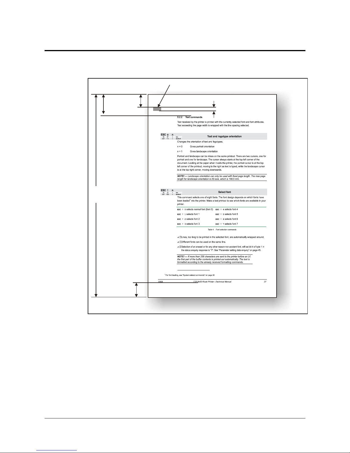
Page setup
0602 TTP 2000 Kiosk Printer–Technical Manual 69
7 PAGE SETUP
7.1 Printable area
n41, n42
n39
Black Mark on back o
f
page
n43, n44
n49
n37, n38
Top margin, bottom margin, page length, and synchronization with preprint are set up
with parameters in the printer.
Page 71
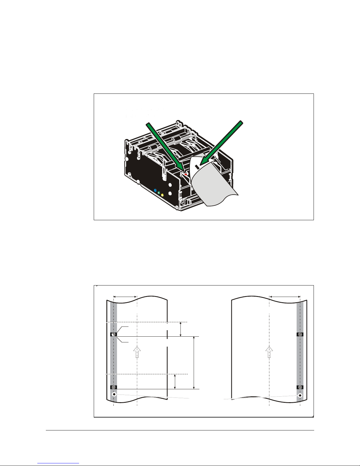
Page setup
70 TTP 2000 Kiosk Printer–Technical Manual 0602
7.2 Aligning preprint and thermal print
The printer can synchronize the cutting of the printout with black-marks printed on the
back of the paper. You use this function when you have preprint on the printout and you
don't want a cut in the middle of that preprint, or text printed on top of the preprint.
Black-mark on
back of paper
Black-mark and
paper-out sensor
Figure 30. Black mark sensor
The sensor used to detect the black-marks is the same sensor as used for paper end
detection. The sideways position depends on which paper guide is fitted. With 58 and
60 mm guides it is 22 mm to the left of the paper center, and with 80 and 82.5 mm
guides, it is 30 mm to the right of the paper center. The distance from the sensor to the
cutter is 25 mm. The sensor accuracy is about ±0.5 mm so avoid designing receipts with
too high demands for synchronization.
Paper viewed from thermalcoating side so black marks
are on opposite side
Min. page
length
(See specifications)
30 mm
Paper
feed
direction
Preprinting not
recommended
within this zone
Cut line
Cut line
25 mm
Black mark size 5 x 9 mm
25 mm
22 mm
Punched hole 5 mm
∅
Paper
feed
direction
or
58 and 60 mm paper 80 and 82.5 mm paper
C
L
C
L
Figure 31. Recommended black mark size and position
Page 72

Page setup
0602 TTP 2000 Kiosk Printer–Technical Manual 71
The sensor triggers on the black-to-white transition of the black-mark, which is when the
black print ends (trailing edge).
Since the same sensor is used for both paper end and black-mark detection, the printer
must know the length of the black-mark to avoid signaling end-of-paper when it detects a
black-mark. The default setting accepts black-marks in the range 3 –16 mm, and works
perfectly with the recommended black-mark length of 5 mm. Marks shorter than 3 mm are
interpreted as dirt, and marks longer than 16 mm as out-of-paper. You can change both
these values by changing the printer default settings.
Black mark mode is selected by setting parameter 36 to 2, and storing the parameters.
NOTE! – It is essential that you store the parameters in the printer for black mark
synchronization even if you enable black marks in the Windows driver.
This is because Windows is not used at paper loading, and feeding with
the FF button on the printer.
7.3 Parameters used
7.3.1 Parameter n36 Document mode
Set to 2 to enables black mark check.
7.3.2 Parameters n37 and n38 - Page length minimum
Measure the distance from the trailing edge of one black mark to the
trailing edge of the next. The resolution is 0.125 mm so multiply the
distance by 8, then calculate the value to enter as n37 and n38.
Example: If the page length is 100mm,
(100 x 8) / 256 = 3.125.
n37 is the integer value, that is 3, while
n38 is the fraction, 0.125 x 256 = 32
7.3.3 Parameter n39 – Max Black Mark length
Measure the height of the black mark. The resolution is 0.125 mm so multiply the black
mark length (in millimeters) by 8 and enter the value as n39.
7.3.4 Parameter n40 – Min Black Mark length (Garbage Filter)
This parameter is actually a filter to filter-out garbage on the paper. If a spot is smaller
than this value, it will not be regarded as a black mark. 1. About ⅓ of the black mark
length is usually a suitable setting.
Page 73
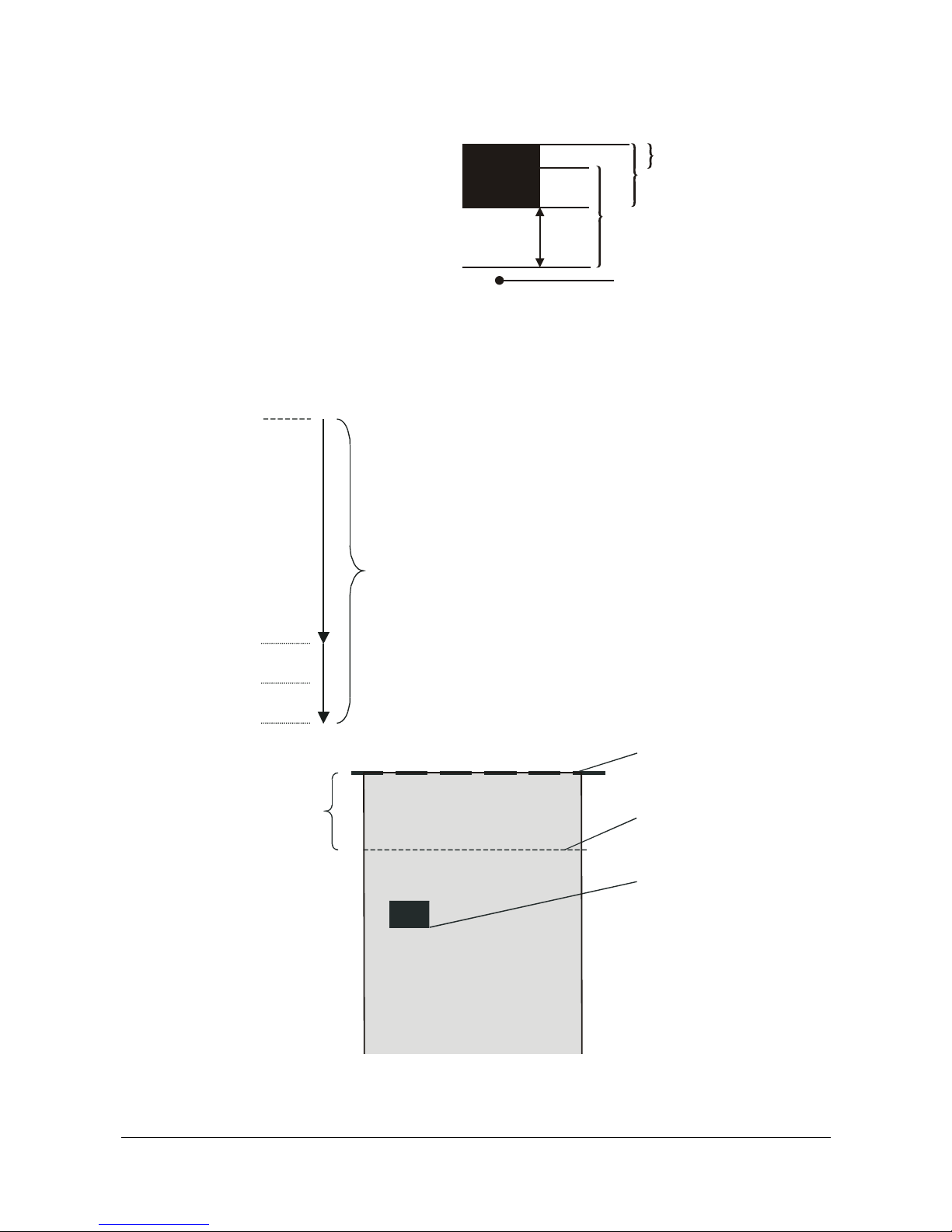
Page setup
72 TTP 2000 Kiosk Printer–Technical Manual 0602
GARBAGE, BLACK MARK AND
OUT OF PAPER DETECTION
For every step the paper is
feed, the black mark sensor
is sampled to detect
garbage, black marks or
out of paper.
When the printer detects blackness is has to check if it is only garbage; if the paper gets
white again within n40 x 0.125 mm, then it is garbage and the spot is ignored. If it is still
black after n40 x 0.125 mm, it is probably a black mark.
If the paper gets white within an additional n39-n40 plus
5 mm then it is a Blackmark. The 5-mm is a constant
added to make sure that noise on the edge not will
interfere with the samples. If it at this point still is still black
we have detected out of paper.
Be careful about n40 and n39. If n39 – n40 is to small,
then the minimum detection area will be too little. This
area should not be less than 2 mm.
7.3.5 Parameter n41 and n42 –Black mark cut offset
After the black mark is detected (black to white change)
the printer feeds another distance to place the paper in cut
position. This distance cannot be negative so placing the
black mark too close to the paper edge is better than too
far away.
n41 & n42
The actual cut position
Desired cut position
Black mark detected
(ESC x n1 n2 is an obsolete command that sets n41 and n42. It is implemented for
backward compatibility with old drivers. Set parameters n41 and n42 with the
ESC & P n1 n2 command instead.)
n37 &
n38
n39
10 mm
Detectio
n
area
Garbage range n40
Printed black mark n39
Valid black mark range (n39 – n40 + 5mm)
5 mm
Constant
Out of paper
Page 74

Page setup
0602 TTP 2000 Kiosk Printer–Technical Manual 73
FF (FORM FEED)
Use FF to print the buffer content, go to the next top of form (black mark), and cut the
paper.
ESC Z (GO TO NEXT TOP OF FORM)
Use ESC Z to move the paper to the next top of form. This is practically a Form-Feed
without printing and cut. It searches for the next black mark for maximum one page length
+ black mark length (256 x n37+n38 + n39)/8. An additional length of 20mm is added to
be sure to pass the edge of the next black mark. If there is no black mark within the set
distance plus 20 mm, an error is raised.
7.3.6 Example
The commands are used together in the following way:
The following examples are not made for a specific programming language or editor, but
can be implemented with the tools of your choice. The data sent
to the printer
are
marked with “Send
→
”.
When setting up the printer:
Send
→ ESC & P 35d 1d
Enables black mark sync
Send
→ ESC & P 37d 4d
Sets distance between two black marks
Send
→ ESC & P 38d 0d
n37=4d and n38=0d gives 128 mm
Send
→ ESC & P 39d 80d
Sets max Blackmark to 80 x 0.125 = 10mm
Send
→ ESC & P 40d 24d
Sets max Blackmark to 24 x 0.125 = 3 mm
Send
→ ESC & P 41d 0d
Send
→ ESC & P 42d 200d
Sets Blackmark offset to 200 x 0.125 = 25mm
Send
→ ESC & P 43d 0d
Send
→ ESC & P 44d 0d
Sets Blackmark top margin to 0mm
Send
→ ESC & 4d
Stores the above parameters as default parameters.
The above set up and stores the parameters in the flash prom of the printer, so this need
only be sent once to the printer when setting it up for Blackmark sync.
Document:
Send→ the text and graphics
At the end of the document:
Send→
ESC Z
Feeds the printout to the next black-mark + the additional feed
specified by the
ESC x
command.
Send
→
RS
Cuts and ejects the printout.
Simple calibration process:
1. Enable black mark mode by setting parameters n36 - n42 as described on the
previous pages.
Page 75

Page setup
74 TTP 2000 Kiosk Printer–Technical Manual 0602
2. Load paper with black marks into the printer
3. Send the
ESC #
command and wait until the paper stops
4. If the paper has returned to it's original position, the calibration is finished
5. If not, it was not possible to distinguish the black mark. Check the n37 and n38
settings and try again).
6. Save the settings with
ESC & 4
7.4 Black-mark sensing from within "Windows"
In Windows, the printer driver
controls when the paper is
cut and ejected. Settings in
the driver override the default
parameter settings in the
printer.
The settings are available in
the Windows
Printing
Preferences Menu
, in the
Advanced Options window.
The names of the options
box differ between driver
versions, but the same
settings are available:
You set n36 to 2 by setting
Page Type to Black Mark,
and Black Mark Check: True.
You set n37, n38 by setting
Paper Size. If no standard paper size is corresponds to the page length you have, create
a new form with that length in the Windows "Printer Server Properties".
You set n39 by setting
Maximum Black mark: to the length of the black mark on your paper
You set n40 by setting
Minimum Blackmark: to the value you want for garbage filter
You set n41, n42 by setting
Cut Position: to the length of transport that you want between black mark and cut.
HINT! – When everything is set up correctly and the printer p rints a s it should;
print a page, then without switching the power off, send the store parameters command
ESC & 04h to the printer (for example using the PRTMON.EXE program from
www.swecoin.se
. If you do this, parameters that the driver uses are stored in the printer
as default parameters. This way the printer synchronizes on black mark also when yo u
load paper, if you press the FF button, etc.
Page 76
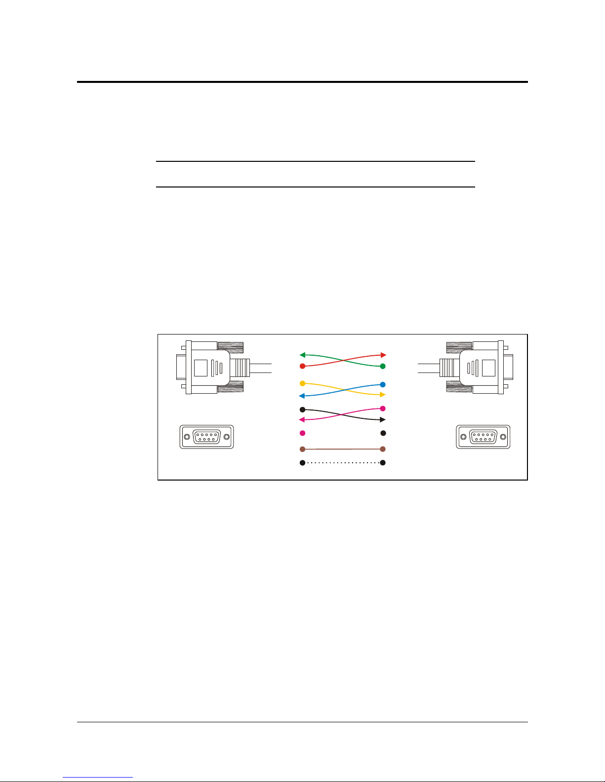
Interface
0602 TTP 2000 Kiosk Printer–Technical Manual 75
8 INTERFACE
The printer has one standard interface, and an optional serial interface. There are no
selections to be made, but only one interface can be used at a time. The printer will not
function properly if data is received on more than one interface at a time.
NOTE! — If you use the printer through a Windows driver, you need not read
the rest of this chapter.
8.1 Serial, TTP 2010
The RS-232 interface of the TTP 2010 printer has a transfer speed that can be set to
between 2 400 and 115200 bits/s.
Applications where text-only printouts are to be printed are suitable for serial interface
because of its easy to use bi-directional capability. The relatively low transfer speed limits
the printing speed when printing graphics. Full-width graphics with 115 200 bits/s result in
printing speeds of about 24 mm/s for the 80-mm version of the printer.
Printer
PC
Female
594837261
Female
594837261
2RxDRxD2
3TxDTxD3
9RIRI9
6DSRDSR6
8CTSCTS8
4DTRDTR4
7RTSRTS7
1DCDDCD1
5GNDGND5
Serial Cable 10825-000
Figure 6. Serial connector pin assignment
Setup options
Baud: 2 400, 4 800, 9 600, 19 200, 38 400, 57 600, and 115 200 bits/s
Flow control: None, Xon / Xoff, or Hardware
Data bits: 7/8
Stop bits: 1 (fixed)
Parity: None, Odd, or Even
Default settings: 9600 bits/s, 8-bits, No parity, 1 stop bit, and hardware flow control.
See also: Default parameter settings on page 27
Page 77

Interface
76 TTP 2000 Kiosk Printer–Technical Manual 0602
8.2 Parallel, TTP 2020
The TTP 2020 parallel port is bi-directional and support Compatibility and
Reverse-Nibble modes.
NOTE! – If you intend to use any other mode than Compatibility Mode, we recommend
you to get the documents for the IEEE-1284 standards, and study them thoroughly.
Pin Host
IEEE1284-A
(D-Sub)
Direction Pin Printer
IEEE1248-C
Compatible
Signal
names
Nibble and
byte mode
Signal
names
1
Ö
15 nStrobe HostClk
2-9
Ö
6-13 Data Data
10
Õ
3 nAck PtrClk
11
Õ
1 Busy PtrBusy
12
Õ
5 PError AckDataReq
13
Õ
2 Select Xflag
14
Ö
17 nAutoFd HostBusy
15
Õ
4 nFault nDataAvail
16
Ö
14 nInit nInit
17
Ö
16 nSelectIn IEEE 1284 Active
18-25 GND 19-35 Ground Ground
+Ö
18 Host Logic High
.Õ
36 Peripheral Logic High
Table 7. Signal names for the parallel port.
Signal names starting with "n" are active LOW signals
8.2.1 Error signaling
All errors that are not reset when status is read will set the nFault signal, for example:
•
Head lifted
•
Cutter not home
•
Out of paper
This error also sets the Paper Out/End (PE) together with nFault:
•
Out of paper
NOTE! – The signaling of nFault and PE can be switched on/off with parameter p5.
Page 78
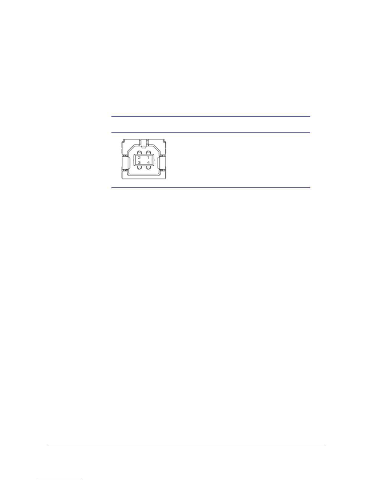
Interface
0602 TTP 2000 Kiosk Printer–Technical Manual 77
8.3 USB, TTP 2030
The USB (Universal Serial Bus) is an interface designed to handle peripherals daisy
chained to a single connector. The transfer speed is up to 12 Mbits/s, which is quite
adequate for the printer. Use this interface in operating systems with USB support, for
instance Windows XP. USB devices are Plug and Play compatible and hot swappable,
which means that they can be connected and disconnected without turning off the power,
or rebooting the computer.
Contact Number Signal Name Comment
1 VCC Cable power
2 – Data
3 + Data
4 Ground Cable ground
Table 8. USB connector (J13) pin assignment
Page 79

Maintenance
78 TTP 2000 Kiosk Printer–Technical Manual 0602
9 MAINTENANCE
9.1 Fault finding
In connection with service of the printer it is good practice to remove paper dust and lint
from the paper path, cutter and sensor areas. Paper dust, when accumulated, may
interfere with printer functions such as optical sensors.
To avoid smudging the paper, do not apply oil on the cutting knife.
Symptom Suggested actions
Nothing is printed when you press
the feed button in self-test mode,
but the document is transported, cut
and ejected.
• Check that the paper roll is turned the correct way with
thermal sensitive layer facing up.
• Check that the paper used meets the paper
• Check that the printhead cable is fully inserted into the
connectors at each end.
Paper jam
• Check cutter-home sensor.
Printer does not work at all
• Check that the printhead is closed.
• Check that power is supplied to the printer.
• Check the function of the paper-out sensor.
Self-test prints OK, but the printer
works strangely in normal operation.
• Check that both ends of the interface cable are
properly connected.
• Application program might be incorrect. Contact system
manager.
No cutting
• Check that the connector for the cutting motor is fully
seated on the control board.
Bad cutting (uneven top and bottom
document edges).
• Switch OFF printer and remove any obstructing paper
particles in cutter and presenter modules.
Inconsistent cutter operation
• Check/clean cutter-home sensor.
Paper is fed straight through the
printer. Paper does not loop.
• Check/clean presenter sensor.
• Check setting of parameter p9.
Missing print or irregular spots.
• Paper may be too humid. Let it adapt to ambient
temperature and humidity for approximately 24 hours
before use.
• The paper used might not meet the paper specification.
White longitudinal lines in the printout.
• Faulty print head, replace.
Faint print.
• The paper used might not meet the paper specification.
• Clean print head with ethyl or isopropyl alcohol.
• Adjust print contrast, see page 74.
Strange characters or graphics
printed, or any kind of strange
printer behavior.
• Might be caused by erroneous data sent from the host.
Check validity of transferred data.
Table 9. Faultfinding
Page 80

Maintenance
0602 TTP 2000 Kiosk Printer–Technical Manual 79
9.2 Cleaning the print head
The print head can be cleaned without removal.
1. Open the printhead.
2. Clean the heat elements with a cotton swab immersed in ethyl or isopropyl alcohol.
9.3 Firmware
The firmware is stored in flash-PROM on the control board. A replacement control board
may not contain the same firmware version that you are currently using, so if you replace
control board for some reason, upgrade it to the firmware version you want to use.
9.3.1 Loading
REMEMBER! – Always design your kiosk system so that remote upgrade of firmware is
possible. If you need to upgrade firmware in the future, the kiosks can
be spread over a vast area and upgrade can become very expensi ve.
Fetch the firmware from the Swecoin web site http://www.swecoin.se. There you will also
find a loader program (Windows™ software) facilitating the loading of the firmware into
the printer.
The loader program contains a help file with detailed instructions on how to load the
firmware into the printer.
In non-Windows environments, use the following procedure to load the firmware:
1. Send ESC NUL (1BH 00H) to the printer.
2. Wait 0.5 seconds.
3. Send the firmware file to the printer.
4. Wait until the printer buzzes to confirm that the loading is complete (the presenter
motor runs for a second).
CAUTION! The loading and burning can take up to one minute. Do not abort before one
minute by turning OFF the power to the printer. Doing so may leave the printer in a state
where new firmware cannot be loaded.
Page 81

Maintenance
80 TTP 2000 Kiosk Printer–Technical Manual 0602
9.3.2 Firmware history
Functions and features are being added from time to time affecting the firmware in the
printer. The following table lists the changes of general interest.
Notice that the list may not contain the latest firmware versions. Please visit our web site
http://www.swecoin.se
for current information.
The firmware number is divided into two section, the header and the version, separated
by a dash.
Firmware header 1814-xxx is for TTP 2020 and TTP 2030
Firmware header 1818-xxx is for TTP 2010
Other headers are for customized versions of the printer and only available for the
customer for whom this version was developed.
A printer can only be updated with firmware that has the same header as the original
number.
The -xxx indicates the firmware version and for example 310 means firmware version
3.10.
FW version Change
1814-310
1818-310
First released firmware version
Changes from last beta-release:
1. Accept larger firmware.
2. Hex mode detects how many bytes can be printed on each line.
3. Power-on reset code, and reset code after firmware-, font-, logo- and
parameter changes cleared up.
4. Communication no longer locks up after loading an oversized font.
5. USB improvements in register and fifo handling
6. Parameter selected font will now check if font is available, use font 0 if
not.
7. Quicker deletion of print nodes, when entered error state. Gives
quicker response of ACK-marker in queue.
8. New fault code (08h) for retract-jam added to Status enquiry (ESC
ENQ 01h), Extended status (ESC ‘E’), and Status LED-indication
1814-320
1818-320
Improvements
1. Added Vertical mode (parameter n57)
2. Added Partial cut (US command).
3. New command (ESC END 05h) has been added to be able the read all
print sensors.
4. Supports new Parallel interface chip on TTP 2020(CPLD), in addition
to the discontinued Intel chip.
5. Improved the automatic speed reduction at low temperatures
Bug fixes
6. Changed SoftReset to fix problems with request sent to printer
during font/logotype/parameter burn.
7. SELECT in the parallel interface will now go low during firmware
burning.
8. PCA revision will be detected correctly
9. Fixed a bug that disabled the loop in black mark mode.
10. Fixed burn-time bug
11. Fixed bug that made Autoload delay disappear after 22 minutes.
Page 82
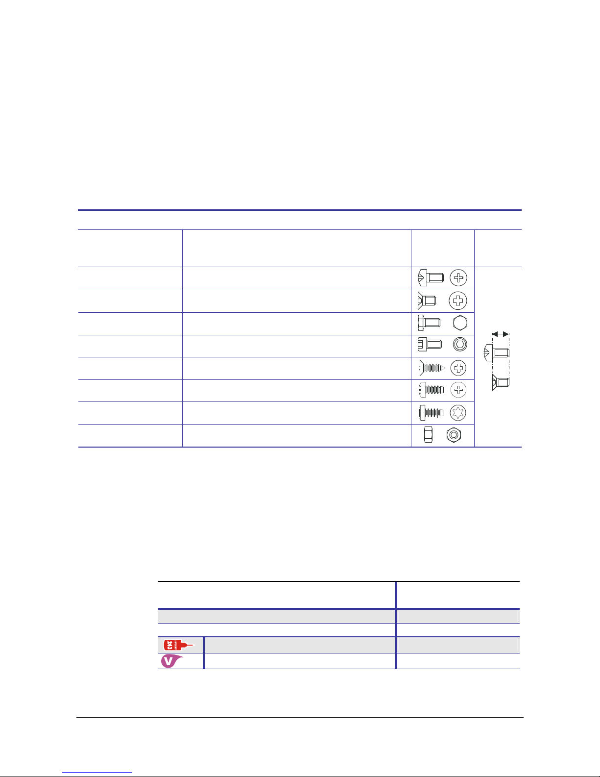
Maintenance
0602 TTP 2000 Kiosk Printer–Technical Manual 81
Replacement parts
Items coded SP are standard replacement parts.
1. Screws, washers, nuts etc. are available in a common hardware store, and are thus
not supplied as replacement parts.
2. Parts that are considered as not being worn by normal printer use are not
replacement parts, for example the printer chassis.
Should you require any of these "non-replacement parts", contact Swecoin for advice.
Other price and delivery conditions may apply for non-coded items.
Standard hardware
Designation example How to interpret the designation Illustration How to
measure
Screw MRX-H M3x5 Panhead screw. Thread: M3. Length: 5 mm
Screw MFX-H M3x6 Countersunk screw. Thread: M3. Length: 6 mm
Screw M6S M6x16 Hex head screw. Thread: M6. Length: 16 mm
Screw MC6S M6x12 Allen-head screw. Thread: M6. Length: 12 mm
Screw FXS-H ST 2.9x6.5
Countersunk. Self-threading. ∅2.9 mm. Length: 6.5 mm
Screw, RXK-H ST 2.9x8
Panhead screw, Self-threading. ∅2.9mm. Length:8 mm
Screw RTK ST 2.9x6.5 Torx panhead. Self-threading. ∅2.9mm. Length: 6.5 mm
Nut M6M M2 Hex nut, M2 thread
Length
DO NOT OVER-TIGHTEN THE SCREWS!
The max torque for the different screw sizes are as follows:
M2 = 0,13 Nm
M2.5 = 0,26 Nm
M3 = 0,46 Nm
M4 = 1.1 Nm
TOOLS, THREAD LOCKING AND LUBRICATION
Tools
Swecoin Part No.
Screwdriver Phillips No. 1 02542-001
Screwdriver Torx T9 02449-009
Thread lock for screws that hold plastic parts 103650
Vaseline spray to lubricate moving parts 104237
.
Page 83

Maintenance
82 TTP 2000 Kiosk Printer–Technical Manual 0602
Item. SP Part No. Designation Qty.
1 X 00375-000 Cog Wheel 2 Pcs.
2 01268-000 Tie wrap 71 x 1.8 mm 1 Pcs.
3 02096-001 Label TTP 2000 Button L 1 Pcs.
5 X 02382-000 Label, "Swecoin" 1 Pcs.
4 02096-002 Label TTP 2000 Button R 1 Pcs.
6 X 09022-309 Nut M6M M2.5 6 Pcs.
7 09045-105 Circlip RS 1.9 2 Pcs.
8 X 09045-107 Circlip RS 3.2 4 Pcs.
9 X 09100-121 Screw MRX-H M2x6 6 Pcs.
10 X 09100-197 Screw MRX-H M2.5x12 1 Pcs.
11 09100-218 Screw MFX-H M3x4 1 Pcs.
12 09101-220 Screw MFX-H M3x6 1 Pcs.
13 09200-188 Screw (TX) MRT M2.5x3 2 Pcs.
14 09200-189 Screw (TX) MRT M2.5x4 2 Pcs.
15 09200-191 Screw (TX) MRT M2.5x6 28 Pcs.
16 100060 Screw MFX-H M2x6 2 Pcs.
17 100479 Screw MFX-H M2.5x12 1 Pcs.
18 X 100481 Spacer DRM 2550x4 4 Pcs.
19 101771 Hub 1 Pcs.
20 102938 Bottom Protection 1 Pcs.
21 102947 Rear Plate 1 Pcs.
22 102949 Pressure Plate 1 Pcs.
23 102950 Front Plate 1 Pcs.
24 102951 Motor Bracket 1 Pcs.
25 102952 Stripper 1 Pcs.
26 102956 Hub 5 Pcs.
27 X 102958 Cutter Blade, Moving 1 Pcs.
28 102959 Side Plate 1 Pcs.
29 X 102963 Cog Wheel 0.5x40 3 Pcs.
30 X 102966 Pressure Roll 4 Pcs.
31 X 102967 Pressure Roll Shaft 2 Pcs.
32 102970 Cutter Drive Plate 1 Pcs.
33 102971 Drive pin 1 Pcs.
34 102974 Leaf Spring 1 Pcs.
35 103082 Cog Wheel 0.5x48 1 Pcs.
36 103083 Shaft Cutter 1 Pcs.
37 103084 Cutter Link 1 Pcs.
38 103090 Cog Wheel 0.5x54 1 Pcs.
39 103136 Hub Nut M2.5x4.0x1.6 3 Pcs.
40 103140 Cover Plate Assy 1 Pcs.
41 103142 Guide 1 Pcs.
42 103144 Spacer M2x35.0 2 Pcs.
43 103145 Spacer M2x40.0 2 Pcs.
44 103146 Side Plate 1 Pcs.
45 X 104399 Thermal Printhead with connector 1 Pcs.
46 X 103273 Sensor board Assy TTP 2000-80, PCA 1 Pcs.
Page 84
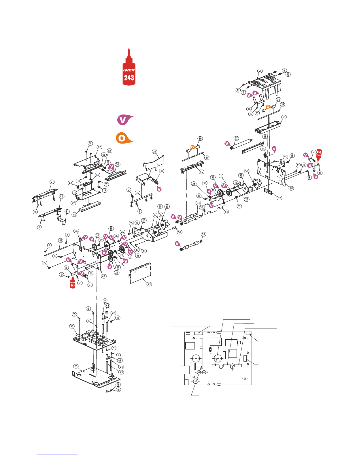
Maintenance
0602 TTP 2000 Kiosk Printer–Technical Manual 83
= Oil
TOF/BM/sensor
Print motor
Cutter motor
Presenter motor
Sensor, outer
Sensor, inner
Printhead
= Vaseline spray
104237
= Apply on thread:
Loctite 243
Threadlocker,
medium strength,
removable, and
oil tolerant
103650
Page 85

Maintenance
84 TTP 2000 Kiosk Printer–Technical Manual 0602
Item. SP Part No. Designation Qty.
47 X 103274 Printhead Cable assy 1 Pcs.
48 X 103275 Opto Sensor Assy, inner 1 Pcs.
49 X 103276 Opto Sensor Assy, outer 1 Pcs.
50 X 103289 Stepper Motor Assy 3 Pcs.
51 X 103306 Cable, Sensor Board 1 Pcs.
52 X 103350 Platen Assy 1 Pcs.
53 X 103351 Feed Roller Assy 3 Pcs.
54 103361 Exit Guide 1 Pcs.
55 103362 Guide front 1 Pcs.
56 103688 Guide 1 Pcs.
57 X 103690 Light Transmitter 2 Pcs.
58 X 102677 Controller Board TTP 2010 PCA 1 Pcs.
58 X 103015 Controller Board TTP 2020, PCA 1 Pcs.
58 X 103716 Controller Board TTP 2030 MKI, PCA 1 Pcs.
59 103725 Hub Nut M2.5x12.5 1 Pcs.
60 103726 Compression Spring SF-TF 0.5x5x9.4 2 Pcs.
61 103747 Shaft 1 Pcs.
62 103748 Cover, Printhead Module 1 Pcs.
63
103845 Label TTP 2030 1 Pcs.
64 X 104029 Bearing, Platen 2 Pcs.
65 X 104030 Bearing, Feed Roller 2 Pcs.
66 X 104032 Cutter blade, fixed 1 Pcs.
67 104097 Compression Spring 0.5x5x9.98 1 Pcs.
Not shown 103848 Complete packaging for TTP 20x0 1 Pcs.
Page 86
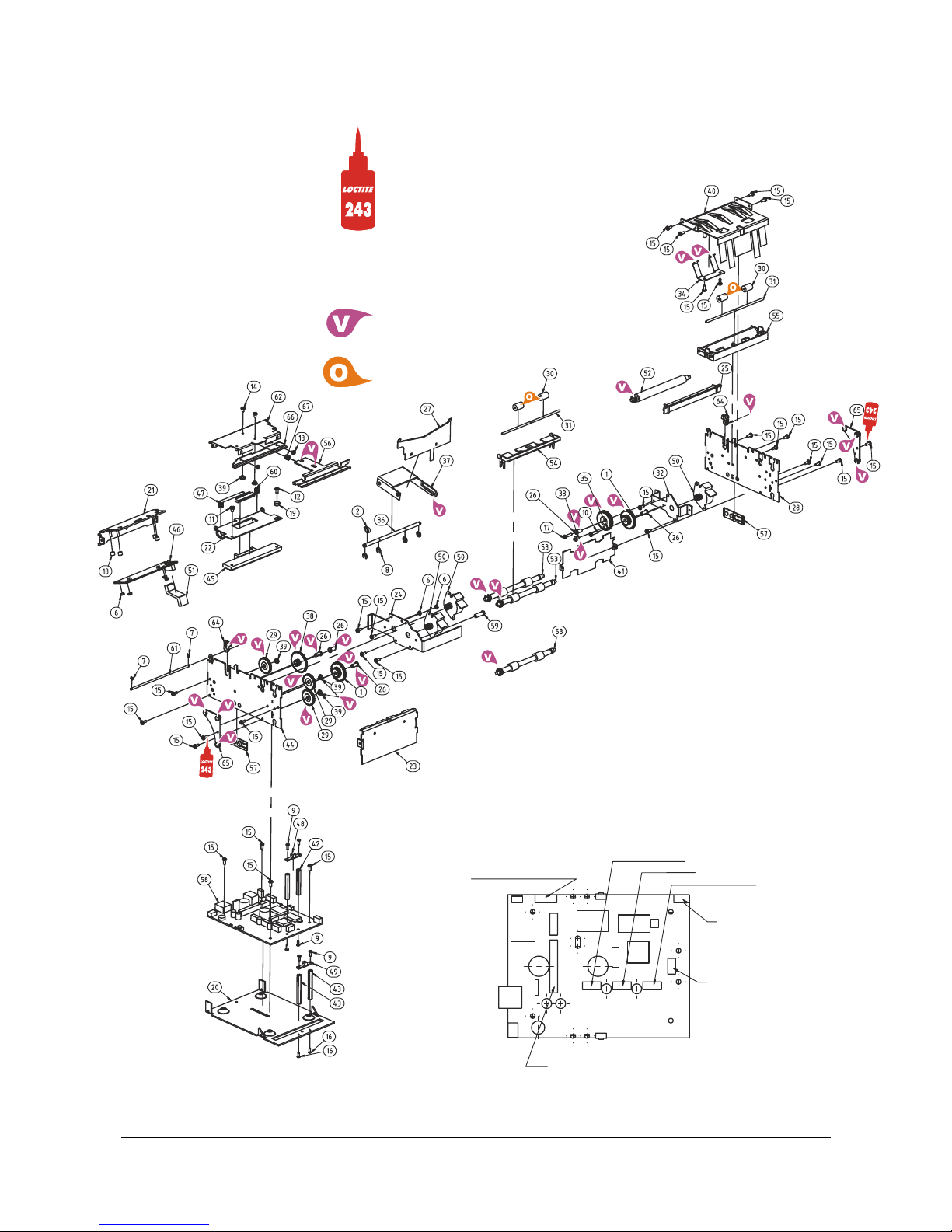
Maintenance
0602 TTP 2000 Kiosk Printer–Technical Manual 85
= Oil
TOF/BM/sensor
Print motor
Cutter motor
Presenter motor
Sensor, outer
Sensor, inner
Printhead
= Vaseline spray
104237
= Apply on thread:
Loctite 243
Threadlocker,
medium strength,
removable, and
oil tolerant
103650
Page 87

Specifications
86 TTP 2000 Kiosk Printer–Technical Manual 0602
10 SPECIFICATIONS
10.1 General
Printer control Windows and Linux drivers.
Text print with ESC commands for formatting.
Print method Direct thermal line printing
(no ink, no toner, no ribbons, just the paper)
Resolution 8 dots/mm (203 dpi)
Print speed Up to 150 mm/s
Max print width
- 58 mm and
60 mm paper 54 mm = 432 pixels
- 80 mm and
82.5 paper 72 mm = 576 pixels
Interfaces
- TTP 2010 Serial RS 232
- TTP 2020 Parallel IEEE 1284
- TTP 2030 USB
Presenter Looping presenter with pull detector, and retract & retain function.
Stepper motor control for exact positioning
Loop storage length 70 to 600 mm (max length may be limited by space in kiosk)
Cutter Guillotine cutter. Stepper motor driven.
10.2 Paper
Paper supply Roll paper
Image life More than 25 years with appropriate paper quality.
Roll diameter 250 mm max (can be less depending on roll holder design)
Spindle diameter 40 mm (25 mm minimum)
Paper width 58, 60, 80, and 82.5 mm
Paper weight 55 –110 g/m
2
(0.054 – 0.11 mm)
Paper sensors Out of paper, paper in presenter, paper in retract path, black mark,
and input for external paper-low sensor.
Specification subject to changes without notice.
Page 88
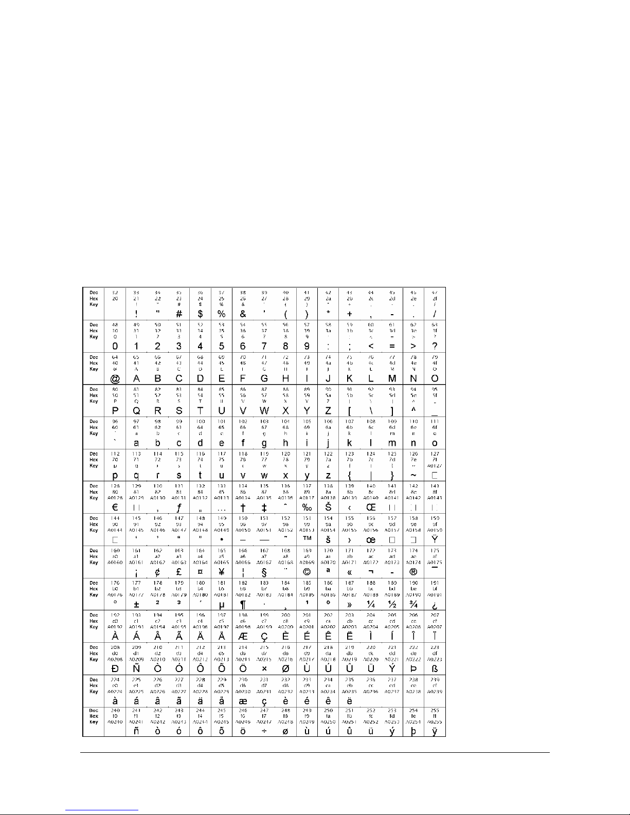
Specifications
0602 TTP 2000 Kiosk Printer–Technical Manual 87
10.3 Text Mode
Orientation Horizontal (portrait mode) and Vertical (Landscape mode)
Standard fonts ATM9, 14 pixels/character fixed spacing font
Characters/line 30 characters on 58 mm and 60 mm paper using ATM9 font
(max 61 characters using 29 cpi font)
41 characters on 80 mm and 82.5 mm paper using ATM9 font
(Max 82 characters using 29 cpi font)
Text attributes Underline, Bold, Italics, reverse print, multiple width and height
Bar codes EAN, UPC, Interleaved 2-of-5, ISBN, Code 39, EAN128 and Code128
Graphics Logotypes and b&w BMP-files
10.3.1 Basic character set
The default fonts use
Windows code page
1252 Western which
contains ISO 8859-1
(ANSI) characters.
You can use other
character sets by
creating and loading
appropriate font files.
Characters 0 to 31
are control codes that
cannot be changed,
but 32 to 255 can be
custom designed.
The table below
shows the characters
stored in flash PROM
on the printer control
board.
Table 10.
Code page
1252 character table
Page 89

Specifications
88 TTP 2000 Kiosk Printer–Technical Manual 0602
10.4 Miscellaneous
Environment 0°C to +50°C, 35% to 75% RH, non-condensing
Size 107 x 68 x 144 mm (w x h x d)
Weight 1.1 kg
Power requirements 24 Vdc ±5% average 2 A when printing, 85 mA idle.
10.5 Life Expectancy
Printhead More than 100 km paper
More than 1x10
8
pulse lines (typically)
Control board 90 000 hours (typically)
Cutter 1 000 000 cuts (typically)
Page 90

Specifications
0602 TTP 2000 Kiosk Printer–Technical Manual 89
10.6 Ordering number list
10.6.1 Printer assembly
Evaluation
Printer
1
kit2
TTP 2010 (Serial) 01971-000 01971-800
TTP 2020 (Parallel) 01972-000 01972-800
TTP 2030 (USB) 01973-000 01973-800
10.6.2 Accessories
Shown on page:
Paper Guide Kit 58 mm 01970-058 10
Paper Guide Kit 60 mm 01970-060
–“–
Paper Guide Kit 80 mm 01970-080
–“–
Paper Guide Kit 82.5 mm 01970-082
–“–
Paper-low sensor w. 300 mm cable (5-15 mm focal dist) 01890-300
Serial cable RS232, 9-pin, 1.5m 10825-000 16
Boot Cable, 9-Pin, 1.5m 01902-000
Parallel Cable A-C IEEE-1284 1.8m 01366-000 17
Parallel Cable 90°A-C IEEE-1284 1.8m 01366-090 17
USB cable 1.8 m 01542-000 17
Roll holder for
∅
200 mm, adjustable position. 58-82.5 mm 103938 92
Mounting plate for the above roll holder 104208 92
Wall mount roll holder for
∅
150 mm roll below. 58-82.5 mm 104123 94
Shelf mount roll holder for
∅
150 mm roll below. 58-82.5 mm 104126 93
Paper roll 58 mm
∅ ≈
150 mm, 60g/m², length 300 m 01942-058
Paper roll 60 mm
∅ ≈
150 mm, 60g/m², length 300 m 01942-060
Paper roll 80 mm
∅ ≈
150 mm, 60g/m², length 300 m 01942-080
Paper roll 82.5 mm
∅ ≈
150 mm, 60g/m², length 300 m 01942-082
Technical manual 103471
Printer driver CD, Windows and Linux 101368
Quick-fit hub kit (2 pcs w. screws), see Figure 6 103939 12
Leaf-spring retainer for quick-fit hubs 01473-000 14
75W Power supply unit with 1.8m secondary cable
3
01776-000 95
150W Power supply unit with on/off switch, and 500 mm
secondary cable
4
01035-014 95
NOTE! – Mains cord is not included in the PSU's.
1
One paper guide is included with each printer. Please indicate what width you want on
your orders.
2
Evaluation kits contain printer, all paper guides, roll holder with 58 and 80mm paper rolls
and sensor, interface cable, power supply, documentation and drivers.
3
Mains cord is not included in the PSU's.
Page 91
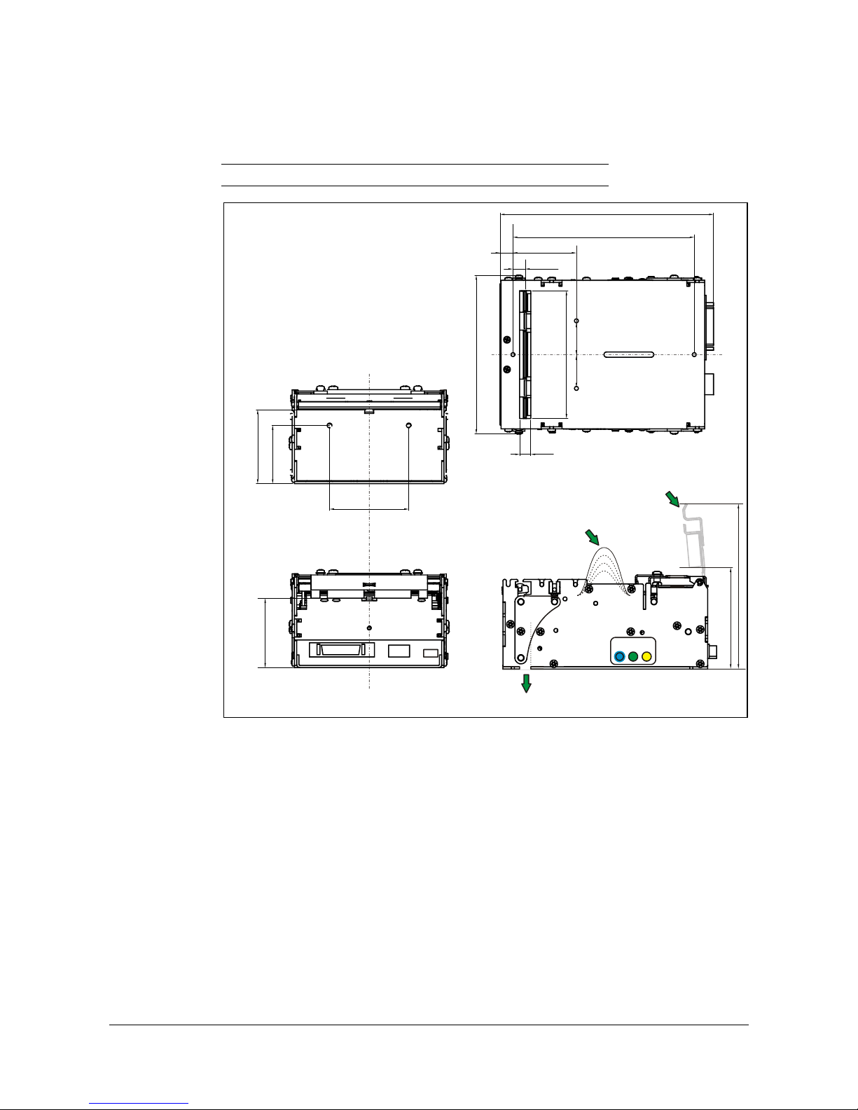
Specifications
90 TTP 2000 Kiosk Printer–Technical Manual 0602
10.7 Dimensions
10.7.1 Printer
NOTE! – Additional space is required for paper roll and handling
Retract output
107
8
C
L
86
25
9
122
144
8.25
Paper
entry
Paper
exit
50
46
53
39
The paper path
is centered around
C
L
68
110
Presenter
loop area
Use M3 screws for fastening printer
Max length = 4 mm inside printer
Printhead
open
C
L
F
e
e
d
P
o
w
e
r
S
t
a
t
u
s
R
C
L
C
L
25
45
Figure 32. Measurements drawing
Page 92
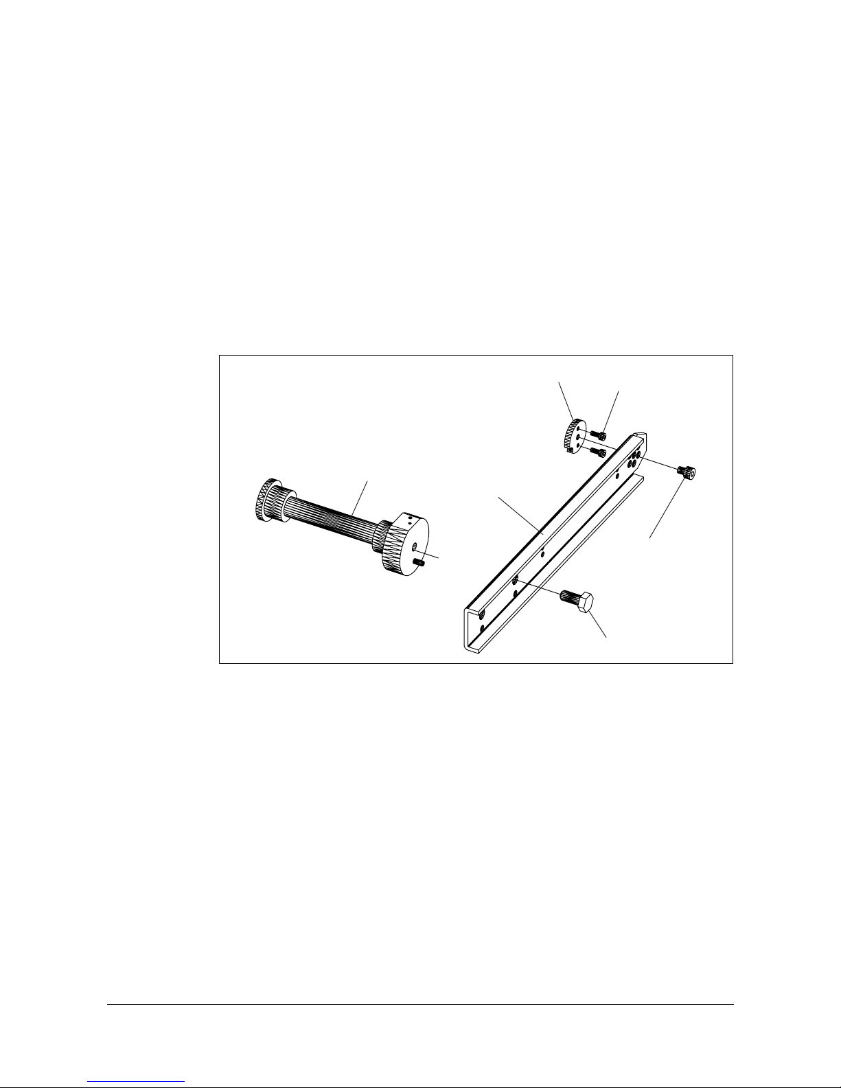
Specifications
0602 TTP 2000 Kiosk Printer–Technical Manual 91
10.7.2 Universal roll holder
This roll holder can be fitted on the right or left side of the printer. The arm can be set in
three different angles. This makes make integration in the kiosk easy.
58 mm, 60 mm, 80 mm, and 82.5 mm paper widths can be used without adjustments.
The universal roll holder takes Ø200 mm rolls in the two high and low positions of the
arm, and 250 mm rolls in the “under” position.
The arm only is required in the high position, while the guide plate with integrated strainrelief is required in the two other positions.
The optional paper low sensor can be fitted.
M2.5x6
M4x5
Roll support
Holder arm
Spacer
M6x14
Figure 33. Universal roll holder
1) Fit the spacer on the side of the printer where you want the arm using the
two M2.5x6 screws.
2) Push the arm onto the spacer screw heads in one on the three usable
angles (Note that if you use the arm without the guide plate, only the
high position is possible to use.)
3) Fasten the arm with the M4x5 screw
4) Move the roll support to the outermost position if you want to use bigger
rolls.
5) Fit the optional paper low sensor onto the roll support, fasten the cable
with tie wraps, and connect it to the connector on the back of the printer.
Page 93
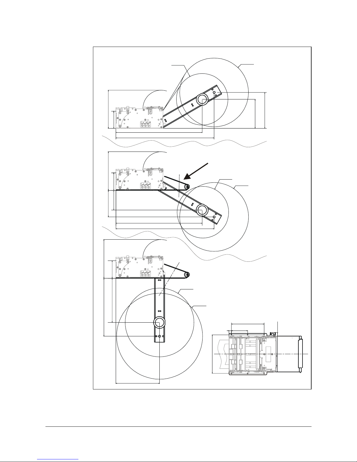
Specifications
92 TTP 2000 Kiosk Printer–Technical Manual 0602
High position
Low position,
with guide plate
Under position,
with guide plate
Ø150 mm paper roll
84 mm
105 mm
Ø200 mm
paper roll
50
51
Min space 111Min space 113
51 128
Min space 113
169
127
95
47
8
112
10
Ø150 mm paper roll
Ø200 mm
paper roll
Ø250 mm paper roll
Ø200 mm
paper roll
57
77
251
285
251
285
Figure 34. Universal roll holder, measurements drawing
Page 94
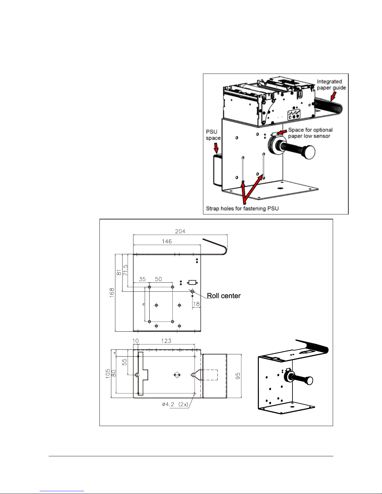
Specifications
0602 TTP 2000 Kiosk Printer–Technical Manual 93
10.7.3 Shelf type roll holder below, Ø150 mm rolls
This roll holder fits all paper widths,
58 mm, 60 mm, 80 mm, and 82.5 mm
without adjustments,
and it takes Ø150 mm rolls.
It has the quick fit fastening so you
just connect the cables to the printer
then slide it onto the roll holder. It
also has additional holes so that you
can attach the 75W PSU with straps,
and fit an optional paper low sensor.
This makes it an ideal evaluation roll
holder, which stands stable on your
desktop, but also can be fastened
into your kiosk and used in normal
installations.
104126
Figure 35. Roll holder 104126 measurements drawing
Page 95
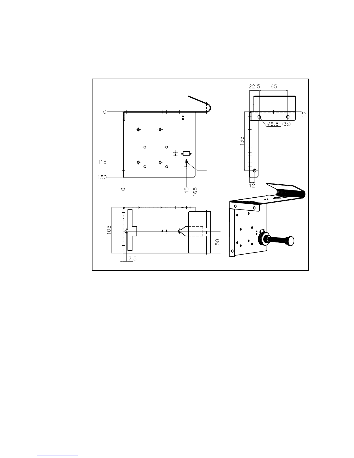
Specifications
94 TTP 2000 Kiosk Printer–Technical Manual 0602
10.7.4 Kiosk wall type roll holder below, Ø150 mm rolls
This roll holder fits the same holls as the above but attaches to the front kiosk wall instead
of a shelf.
Roll center
104123
Figure 36. Roll holder 104123 measurements drawing
Page 96
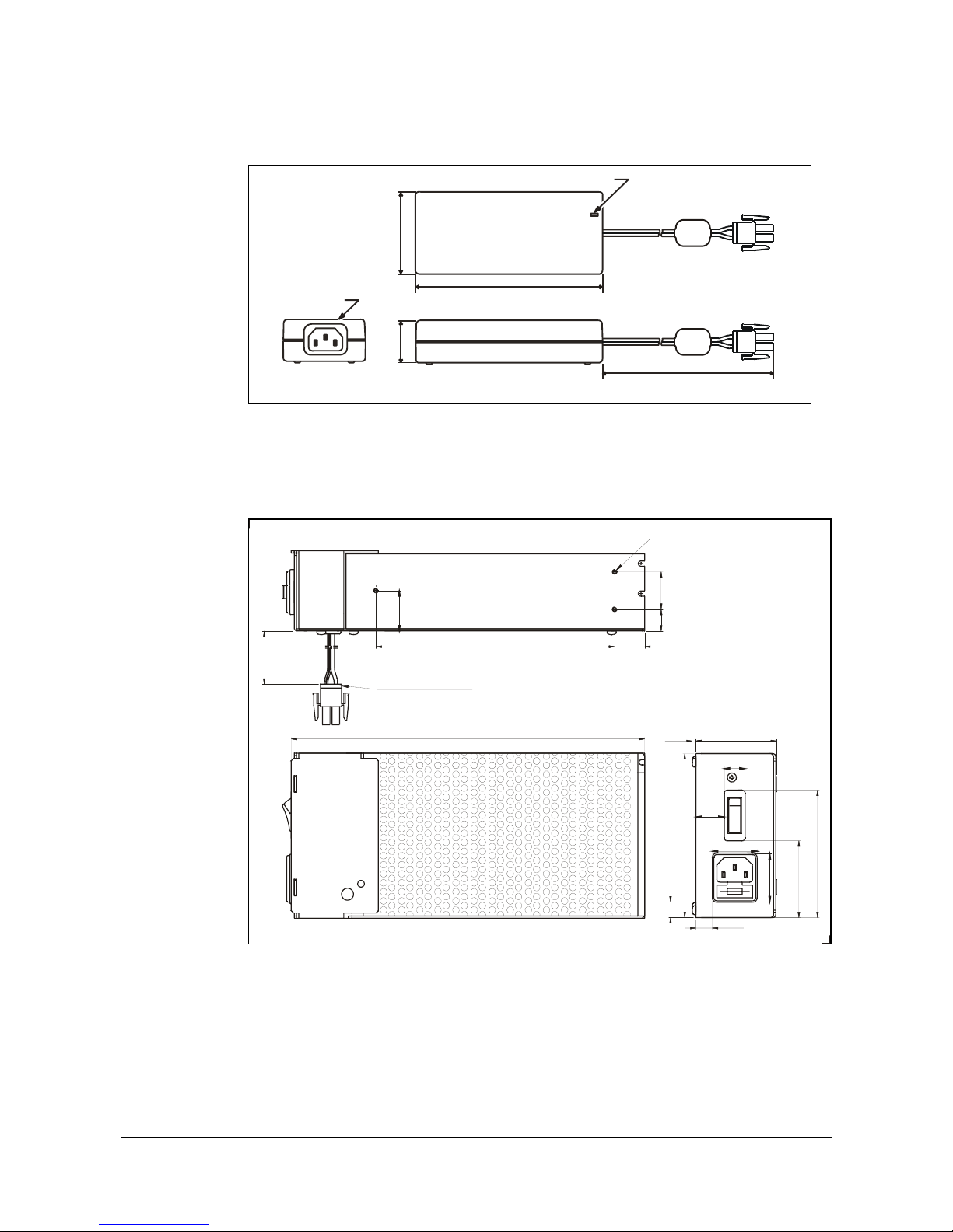
Specifications
0602 TTP 2000 Kiosk Printer–Technical Manual 95
10.7.5 75W Power Supply
1.8 m
IEC320/C14
Power ON indicator
58
132
30
01776-000
Figure 37. Measurements of 75W PSU
10.7.6 150W Power Supply
54.02.5
1
1
0
.
0
1
0
.
5
11. 0
30.0
3
2
.
5
5
1
.
5
8
5
.
5
19.0
14.0
1
4
.
5
2
5
.
0
2
7
.
0
M3 (3x)
235.5
159.0
20.0
Cable 01370-000
5
0
0
.
0
SW99013
Bottom view
Figure 38. Measurements of 150W PSU
Page 97

Index
96 TTP 2000 Kiosk Printer–Technical Manual 0602
Index
2
2-of-5 Interleaved .........34
A
Accessories .................. 89
ACK.............................. 46
Acknowledge marker.... 53
Add-on, bar code.......... 35
Aligning preprint and
thermal print ............. 70
Alignment .....................30
Ambient light................. 15
ANSI............................. 87
Auto cut after FF........... 64
B
Backspace.................... 32
Barcodes ...................... 34
Baud rate...................... 61
Black-mark ............. 29, 70
Check ....................... 21
Length ......................66
Sensitivity ........... 67, 74
BMP-file........................ 36
Bold .............................. 31
Bootware ...................... 51
Bottom margin .............. 67
Brightness ....................21
Burn time ...................... 62
Buttons ........................... 8
C
Calibration .............. 29, 67
Cancel .......................... 32
Carriage return .......32, 64
Center align .................. 30
Character set................ 87
Cleaning the printhead . 79
Clear presenter. 21, 41, 68
Code page.................... 87
Code128....................... 34
Code39......................... 34
Commands summary ...27
Connecting to the
computer ............ 16, 17
Connector
Interface ...................16
Paper Low ................ 15
Power ....................... 18
Contrast........................ 21
Control board revision .. 50
CR/LF behavior ............64
Current consumption18, 62
Cut................................ 40
Cut and eject................. 40
Cut offset ...................... 66
Cutter not in home
position ..................... 46
D
Data bits ....................... 61
Decimal ........................26
Decimal codes........ 27, 60
Default settings ............ 59
Serial interface ......... 75
Store ........................ 43
Dimensions .................. 90
Document Mode
BM............................ 64
Fixed ........................ 64
Variable.................... 64
Dot-line......................... 36
Drawing
shelf ......................... 14
Driver
Installation................ 20
Mode ........................ 25
Settings .................... 20
Status Monitoring ..... 20
E
EAN128........................ 34
EAN13.......................... 34
EAN8............................ 34
Earth currents............... 15
Eject ............................. 41
Eject length .................. 67
Enclosure ..................... 11
Enforced clear presenter41
Error codes......... 9, 46, 58
ESD.............................. 15
F
Fault finding.................. 78
Feed button .............. 8, 19
File format
Font.......................... 54
Logotypes................. 56
Firmware ...................... 50
history ...................... 80
loading ..................... 79
Fixed Document Mode . 64
Flow-control.................. 61
Fonts .... 30, 44, 47, 63, 87
file format ................. 54
loading ..................... 54
Form feed..................... 33
G
Garbage Filter .............. 66
Ground ............ See Earth
H
Hardware handshaking 61
Height........................... 31
Hex............................... 26
Hex codes .............. 27, 60
Hold after print.............. 21
Horizontal mode ........... 68
Humidity ....................... 88
I
I2C options-bus............. 52
IEEE-1284.................... 17
Indicators........................ 9
Installation.....................11
paper roll...................22
paper-low sensor ......15
printer driver..............20
Interface........................75
Connector .................16
Inversed ........................31
ISBN .............................34
ISO 8859-1 ...................87
Italics............................ Se
K
Kiosk .............................11
L
Landscape ....................30
Language monitor .........20
Leaf-spring retainer.14, 89
LEDs ...............................9
Left align .......................30
Life Expectancy.............88
Light ..............................15
Line spacing..................63
Linefeed ..................33, 64
Lines. horizontal............37
Load paper....................22
Loading firmware ..........79
Logotypes....38, 43, 47, 56
file format ..................56
Loop
Disable................42, 63
Length.......................63
Limit ..........................42
Presenter ....................7
M
Maintenance .................78
Measurements drawing.90
Minimum printout length40
Mnemonic .....................26
Mounting shelf ..............14
N
n1, n2, etc. ....................26
NAK ..............................46
Noise, excessive...........62
O
Operation ......................22
Options-bus ..................52
Ordering information .....89
Orientation ....................30
Output slot ....................14
P
Page
Based........................21
Length.......................65
Setup ........................69
Type..........................21
Paper
Advance..............21, 39
Cut mode ..................21
Page 98

Index
0602 TTP 2000 Kiosk Printer–Technical Manual 97
Eject .........................21
Feed backwards ....... 39
Feed error................. 46
Feed forward ............39
Guide............ 10, 70, 89
In presenter ..............46
Jam........................... 24
Low sensor ............... 89
Near-end status........ 47
Ordering numbers .... 89
Page length .............. 40
Reverse .............. 21, 39
Roll installation .........22
Sensitivity ................. 21
Specifications ...........86
Paper-low ..................... 15
Connector................. 15
Parallel
Cable.................. 17, 89
Port........................... 17
Port setup ................. 62
Parameters................... 59
recall......................... 44
reset to default.......... 59
set ............................ 45
store .........................43
Parity ............................ 61
Partial cut ..................... 40
Pin assignment
Serial port ................. 75
USB port................... 77
Pixel-line....................... 36
Plug and Play ........... 6, 51
Portrait.......................... 30
Power
Connection ............... 18
Connector................. 18
Supply .......... 18, 89, 95
Present ................... 40, 41
Slowly....................... 21
Presenter........................ 7
Clear................... 41, 68
Print
bitmap....................... 36
commands................ 39
logotype .................... 38
quality ....................... 62
ruler line.................... 37
Speed............. 6, 21, 62
Print head
lifted.......................... 46
pulse control ............. 63
temperature .............. 50
Printable area ............... 69
Printer
driver ....................6, 20
opening..................... 24
operable ................... 46
out of paper .............. 46
Printout length .............. 40
Printout, self-test .......... 19
Product presentation ...... 6
Programming.......... 27, 60
Protective earth ............ 15
Pull-detector ................. 41
Disable ..................... 68
Q
Quick-fit hubs ............... 12
R
Replacement parts ....... 81
Reporting status ........... 58
Reset
printer................. 43, 46
Retract ............... 7, 21, 66
Reversed...................... 31
Right align .................... 30
Roll
Holders..................... 89
Roll based .................... 21
Roll holders ............ 13, 91
Ruler line...................... 37
S
Scaling ......................... 21
Self-service kiosk ......... 11
Self-test.................. 19, 39
Send dot-line ................ 36
Sensors........................ 47
paper-low ................. 15
status ....................... 49
Serial
Cable........................ 89
Serial cable .................. 16
Serial interface ............. 75
Serial number............... 50
Shelf............................. 14
Short Message Protocol52
Shutter ......................... 52
Specifications ............... 86
Status
acknowledge ............ 53
bytes .................. 48, 49
code ......................... 46
commands................ 46
Extended.................. 52
indicator ..................... 9
messages................. 46
Reporting.................. 58
Store parameters ......... 43
Summary of control
codes & escape
sequences.................27
Syntax...........................29
T
Tab................................33
Stop positions ...........63
Temperature .................50
Error..........................46
Range .......................88
Terminal faults ..............46
Test printout..................19
Text
alignment ..................30
bold ...........................31
commands ................30
height ........................31
italics........................ Se
Mode...................25, 87
position .....................32
reversed....................31
underline ...................31
width .........................31
TOF mark See Black-mark
Top margin....................66
Torque, screws .............81
Trash bin
See ...................Retract
U
Underline ......................31
UPC ..............................34
USB ..............................77
Cable ........................89
Connector .................17
Port ...........................17
V
Variable Document
Mode.........................64
Vertical
Installation.................11
Mode...................21, 68
Voltage indicator .............9
W
Wall Compensation.......67
Warning level ..........67, 68
Waste
See ...................Retract
Width.............................31
Windows ...2, 6, 20, 51, 79
X
Xon / Xoff ......................61
Page 99

98 TTP 2000 Kiosk Printer–Technical Manual 0602
This page is intentionally left blank.
 Loading...