

SWASH SFF1000CSA series, SFF1001CSA series, SFF1002CLN series, SFF1002CSA series, SFF1001CLN series Technical Education

TECHNICAL EDUCATION
L-86
SWASH™ Clothing Care System
SFF1000CSA*
SFF1001CSA*
SFF1002CSA*
SFF1001CLN*
SFF1002CLN*
* Denotes Engineering Revision
JOB AID W10713431

FORWARD
This Whirlpool Job Aid, "SWASH™ Clothing Care System” (Part No. W10713431), provides the In-Home
Service Professional with informaon on the operaon and service of the “SWASH Clothing Care
System."
GOALS AND OBJECTIVES
The goal of this Job Aid is to provide informaon that will enable the In-Home Service Professional to
properly diagnose malfuncons and repair the "SWASH™ Clothing Care System.”
The objecves of this Job Aid are to:
• Understand and follow proper safety precauons.
• Successfully troubleshoot and diagnose malfuncons.
• Successfully perform necessary repairs.
• Successfully return the clothing care system to its proper operaonal status.
WHIRLPOOL CORPORATION assumes no responsibility for any repairs made on our
products by anyone other than authorized In-Home Service Professionals.
Copyright © 2014, Whirlpool Corporaon, Benton Harbor, MI 49022
Whirlpool®/™ is a trademark of Whirlpool U.S.A. Tide®/™ is a trademark of The Procter & Gamble Company. Swash®/™ is a
trademark of Go Unlimited LLC. © 2014. All Rights Reserved. The WHIRLPOOL and TIDE trademarks are used by Go Unlimited
LLC under license. Product manufactured under license for, and warranty provided by, Go Unlimited LLC, Cincinna, OH 45202
ii n
SWASH™ Clothing Care System

SWASH™ Clothing Care System
SECTION 1 — GENERAL INFORMATION
SWASH™ SYSTEM SAFETY ..................................................................................................................1-2
MODEL & SERIAL NUMBER LABEL .....................................................................................................1-3
TECH SHEET LOCATION .......................................................................................................................1-3
SWASH™ SYSTEM................................................................................................................................1-4
SWASH™ SYSTEM OVERVIEW.............................................................................................................1-5
SWASH™ SYSTEM SPECIFICATIONS ....................................................................................................1-5
SECTION 2 — OPERATION
CONNECTING THE SWASH™ SYSTEM .................................................................................................2-2
BUTTONS AND STATUS LIGHTS ..........................................................................................................2-3
HOW DOES THE SWASH™ SYSTEM WORK? ........................................................................................2-4
HOW TO USE SWASH™ SYSTEM .........................................................................................................2-5
HANGING CLOTHES ............................................................................................................................2-6
EMPTYING THE RESERVOIR ................................................................................................................2-8
CONSUMER TROUBLESHOOTING .......................................................................................................2-9
SWASH™ SYSTEM TIPS .......................................................................................................................2-9
TABLE OF CONTENTS
SECTION 3 — COMPONENT ACCESS
SWASH™ SYSTEM EXPLODED VIEW ...................................................................................................3-2
SWASH™ SYSTEM PARTS LIST .............................................................................................................3-3
REMOVING THE REAR PANEL .............................................................................................................3-4
REMOVING THE TOP COVER & CONTROL HOUSING .........................................................................3-5
REMOVING THE USER INTERFACE ......................................................................................................3-6
REMOVING THE DISPENSING SYSTEM ...............................................................................................3-6
REMOVING THE PUMP ASSEMBLY .....................................................................................................3-7
REMOVING THE APPLIANCE CONTROL UNIT (ACU) ..........................................................................3-7
REMOVING THE THERMISTOR ...........................................................................................................3-7
REMOVING THE DOOR ASSEMBLY .....................................................................................................3-8
REMOVING THE CLIPS & ROLLER ASSEMBLY .....................................................................................3-9
REMOVING THE BASE COMPONENTS ..............................................................................................3-10
REMOVING THE SIDE PANELS ..........................................................................................................3-12
SECTION 4 — DIAGNOSTICS & TROUBLESHOOTING
SAFETY FIRST ......................................................................................................................................4-2
CUSTOMER TROUBLESHOOTING .......................................................................................................4-3
CUSTOMER ERROR CODES .................................................................................................................4-3
CONTROL PANEL .................................................................................................................................4-4
DIAGNOSTIC GUIDE ............................................................................................................................4-4
SERVICE DIAGNOSTICS .......................................................................................................................4-4
SERVICE DIAGNOSTIC FUNCTIONS ....................................................................................................4-5
FAULT / ERROR CODES ........................................................................................................................4-6
TROUBLESHOOTING GUIDE ...............................................................................................................4-8
WIRING DIAGRAM ............................................................................................................................4-10
APPLIANCE CONTROL UNIT (ACU) ...................................................................................................4-11
USER INTERFACE (UI) ASSEMBLY .....................................................................................................4-12
STRIP CIRCUITS .................................................................................................................................4-13
SWASH™ Clothing Care System
n
iii

PRODUCT SPECIFICATIONS & WARRANTY INFORMATION SOURCES (inside back cover)
iv n
SWASH™ Clothing Care System

GENERAL INFORMATION
Section 1:
General Information
This secon provides general safety, parts, and informaon for
the “SWASH™ Clothing Care System.”
Q SWASH™ System Safety
Q Model & Serial Number Label
Q Tech Sheet Locaon
Q SWASH™ System
Q SWASH™ System Overview
Q SWASH™ System Specicaons
Q Notes
SWASH™ Clothing Care System
n
1-1

GENERAL INFORMATION
SWASH™ System Safety
Your safety and the safety of others are very important.
We have provided many important safety messages in this manual and on your appliance. Always read and obey all safety
messages.
This is the safety alert symbol.
This symbol alerts you to potential hazards that can kill or hurt you and others.
All safety messages will follow the safety alert symbol and either the word “DANGER” or “WARNING.”
These words mean:
You can be killed or seriously injured if you don't immediately
DANGER
WARNING
All safety messages will tell you what the potential hazard is, tell you how to reduce the chance of injury, and tell you what can
happen if the instructions are not followed.
follow instructions.
You
can be killed or seriously injured if you don't
instructions.
follow
STATE OF CALIFORNIA PROPOSITION 65 WARNINGS:
WARNING: This product contains one of more chemicals known to the State of California to cause cancer.
WARNING: This product contains one or more chemicals know to the State of California to cause birth defects or other
reproducve harm.
IMPORTANT SAFETY INSTRUCTIONS
WARNING: To reduce the risk of re, electric shock, or injury to persons when using the SWASH™ system, follow basic
precauons, including the following:
n Read all instrucons before using the SWASH™ system.
n Use the SWASH™ system only for its intended use.
n To reduce the risk of electric shock, do not immerse any
part of SWASH™ system in water or other liquids.
n Never yank cord to disconnect from outlet; instead, grasp
plug and pull to disconnect.
n Do not allow cord to touch hot surfaces. Let SWASH™
system cool completely before pung away. Loop cord
loosely around SWASH™ system when storing.
n Always disconnect SWASH™ system from electrical outlet
when not in use, or when cleaning SWASH™ system.
n Do not operate SWASH™ system with a damaged cord, or
if it has been dropped or damaged. To reduce the risk of
electric shock, do not disassemble or aempt to repair
SWASH™ system. Contact a qualied service person for
examinaon and repair. Incorrect reassembly or repair
could cause a risk of re, electric shock, or injury to
persons when SWASH™ system is used.
n Close supervision is necessary for any appliance being
used near children.
n Use care when interrupng a cycle; interior surfaces may
be hot if SWASH™ system is opened when in use.
n To reduce the likelihood of circuit overload, do not
operate other high-waage hardware (i.e. refrigeraon,
air condioner, etc) on the same circuit.
n The SWASH™ system is intended for household use only.
Do not use outdoors.
n Do not use in garages or near any ammable liquids.
n Do not use an extension cord.
n The use of accessories other than those supplied with
the SWASH™ system is not recommended and may cause
injury.
n Use and store SWASH™ system out of regularly traveled
paths to reduce the possibility of p-over.
n Keep the area clear around the base of SWASH™ system
to make sure venlaon openings in the boom of
SWASH™ system are not blocked.
n Do not modify SWASH PODS™ cups or use any alternate
formulas. The SWASH™ system was designed to work
safely using only the unique SWASH PODS™ cups. Any
modicaons could reduce user safety.
n Burns could occur from touching hot metal parts.
SAVE THESE INSTRUCTIONS
1-2 n
SWASH™ Clothing Care System
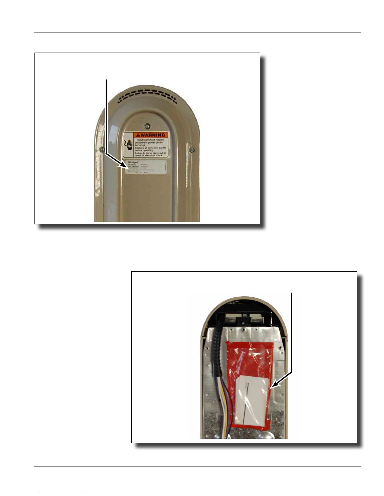
Model & Serial Number Label
Model & Serial Number
Label Location
GENERAL INFORMATION
Figure 1 - Located on back panel of SWASH™ system
Tech Sheet Location
Tech Sheet Location
Figure 2 - Located behind the back panel of SWASH™ system
SWASH™ Clothing Care System
n
1-3
GENERAL INFORMATION
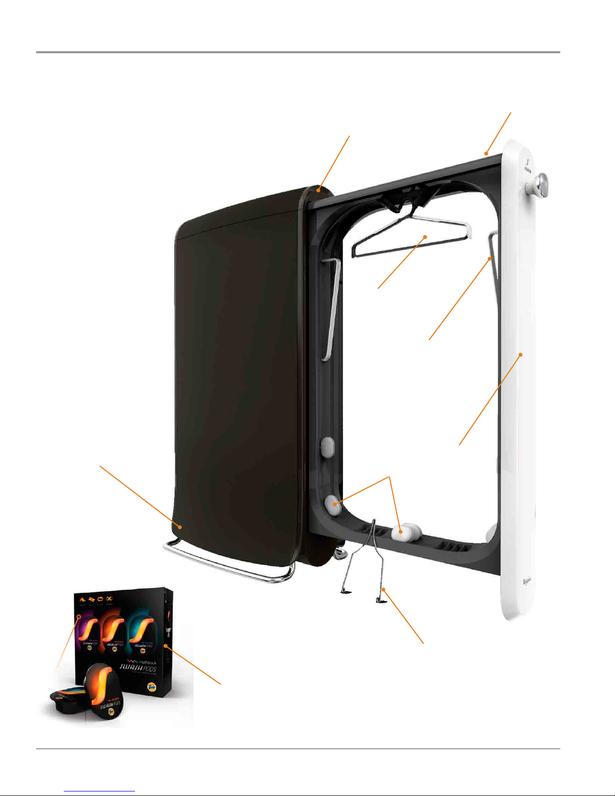
SWASH™ System
SWASH PODS™ BAY
CONTROL PANEL
ADJUSTABLE
HANGER
RESERVOIR
SLEEVE
WRAPS
DOOR
SMOOTHING
CLIPS
SWASH PODS™ CUPS
1-4 n
SWASH™ Clothing Care System
POCKET
SMOOTHER
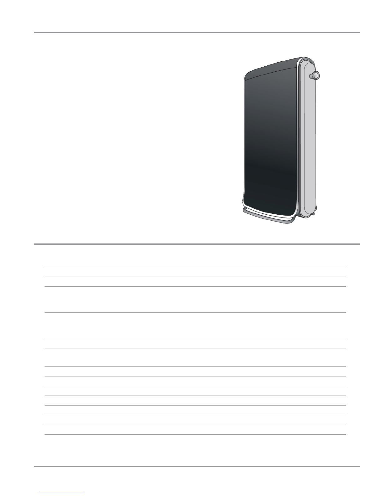
SWASH™ System Overview
SWASH™ Clothing Care System
The SWASH™ system gets clothes looking and feeling their
best. De-wrinkle, Refresh, Restore, and Preserve clothes for
results never before achievable at home with the SWASH
system’s 10 minute express clothing care. The SWASH system,
an all-in-one, in-home, convenient clothing care system, has
elements of a clothes steamer and an iron. Designed to t in
any life-style, the consumer can put the SWASH system almost
anywhere, like their bedroom or closet. It uses a standard wall
outlet, so all they have to do is plug it in and start living life
unhampered.
The SWASH system works with a few key technologies. The
Smoothing Clips provide the right amount of tension; a
superne mist of the SWASH PODS™ formula is sprayed onto
both sides of the hanging clothes, and circulated heat removes
light wrinkles and restores the t to clothes that’s lost aer
wear by ghtening bers without shrinking.
Using the SWASH system is as easy as plugging it into a
standard 120 VAC wall outlet. No water, plumbing, pipes,
vents, special hook-ups, or professional installaon assistance
is needed.
GENERAL INFORMATION
SWASH™ System Specifications
Voltage: 120 VAC, 60 Hz
Heater Waage: 1300 W
Countdown and Display Status: LED Countdown Time Remaining - White LEDs
Cycle Done - Blue LED
Cup Missing - Orange LED
Cycles: Normal - 10 minutes
Heavy Duty - 15 minutes
Cancel
Number of Cycles: 3
Number of Garments: 2-Sided Treatment of 1 Garment
1-Sided Treatment of 2 Garments
Number of Smoothing Clips: 6
Number of Sprays: 4
Pocket Smoother 1
Height: 51 in.
Width: 16 in.
Depth: 30 in.
Depth with door open: 54 in.
SWASH™ Clothing Care System
n
1-5

GENERAL INFORMATION
Notes
1-6 n
SWASH™ Clothing Care System

OPERATION
Section 2:
Operation
This secon provides operaonal use and care informaon for
the “SWASH™ Clothing Care System.”
Q Connecng the SWASH™ System
Q Buons and Status Lights
Q How Does the SWASH™ System Work?
Q How to Use SWASH™ System
Q Hanging Clothes
Q Emptying the Reservoir
Q Consumer Troubleshoong
Q SWASH™ System Tips
Q Notes
SWASH™ Clothing Care System
n
2-1
OPERATION
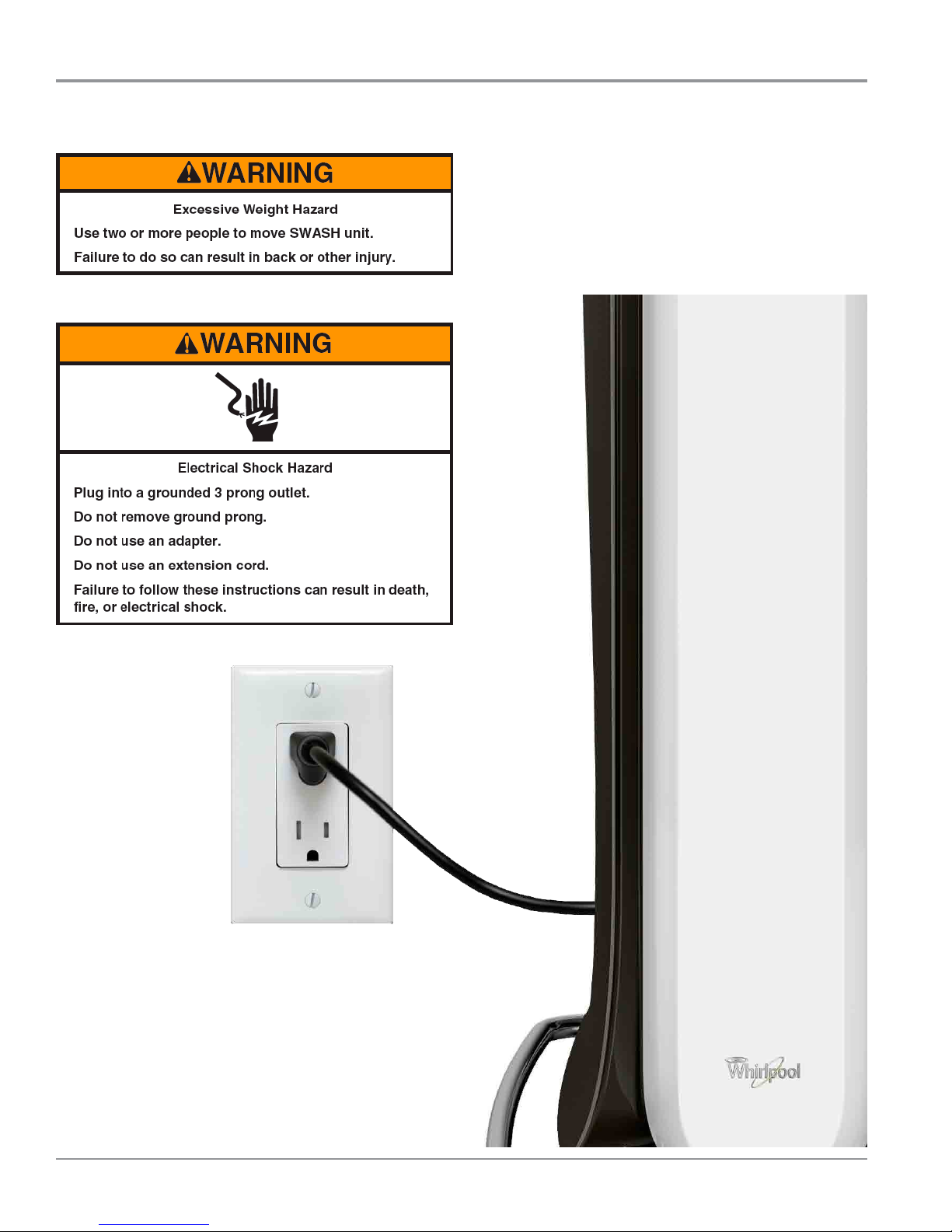
Connecting the SWASH™ System
Connecng the SWASH™ System
Plug your SWASH™ system into a standard grounded electrical
outlet (110v). No plumbing, pipes, or vents needed.
2-2 n
SWASH™ Clothing Care System
Figure 1
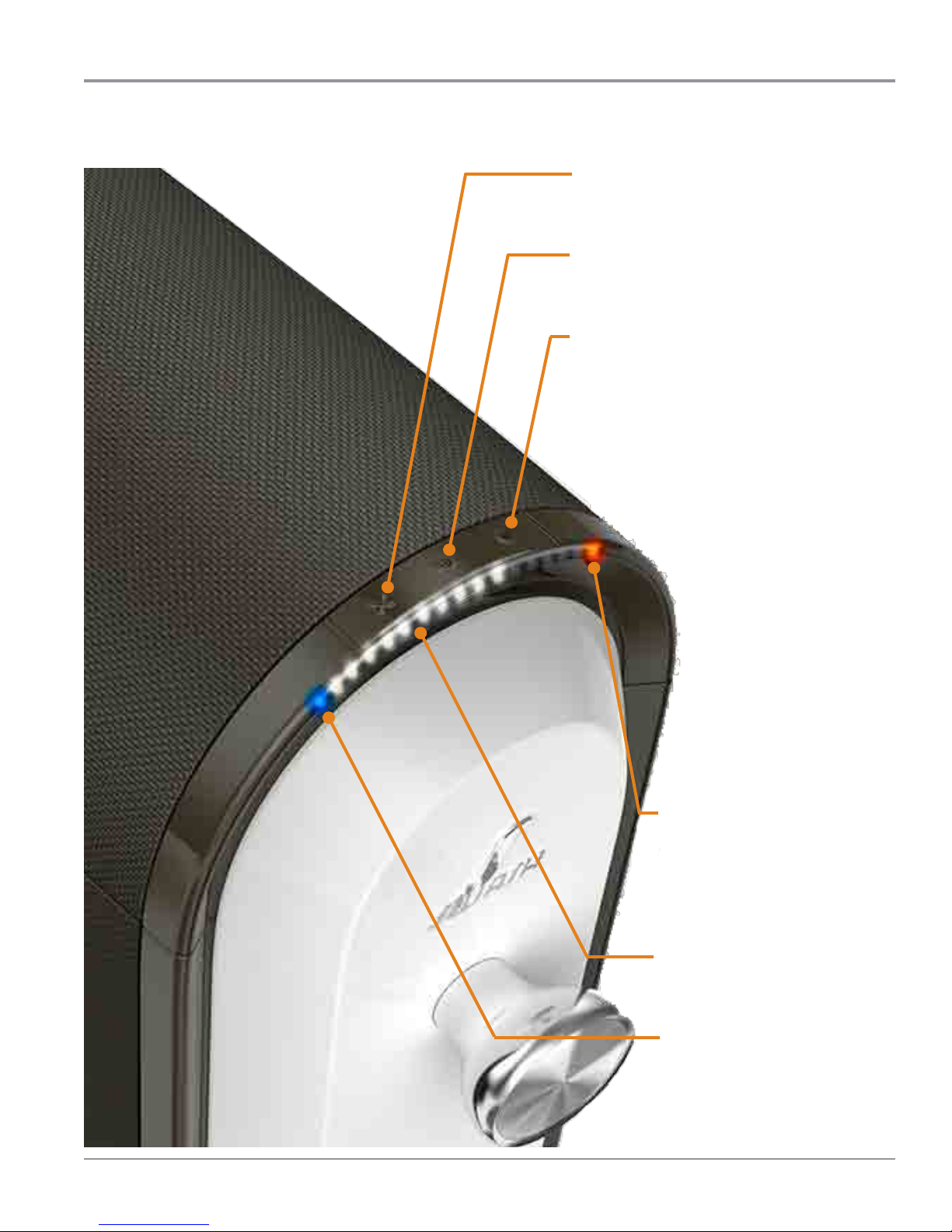
Buttons and Status Lights
X BUTTON
cancels the cycle
10 MINUTE BUTTON (STANDARD CYCLE)
use for most clothing
15 MINUTE BUTTON (EXTENDED CYCLE)
extends drying me for heavier clothing
OPERATION
ORANGE LIGHT
ashes if you try to start SWASH™
system without a cup or if the door
is not completely closed. If other
lights are on with the orange light
(see troubleshoong)
WHITE LIGHTS
count down the minutes remaining
BLUE LIGHT
turns on when your cycle is nished
Figure 2
SWASH™ Clothing Care System
n
2-3
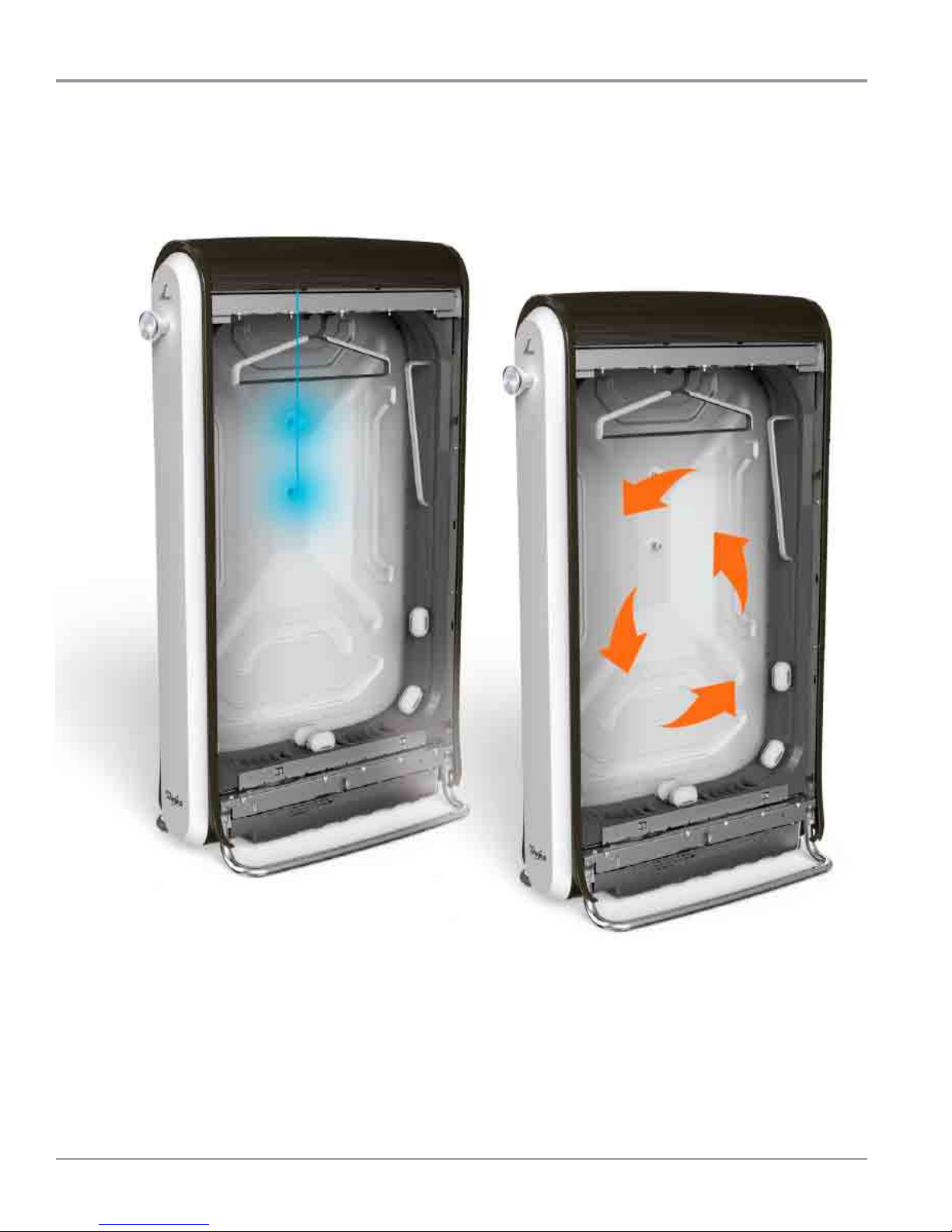
OPERATION
How Does the SWASH™ System Work?
The SWASH™ system works with a few key technologies. A superne mist of the SWASH PODS™ formula is sprayed onto both
sides of the hanging clothes. The smoothing clips (oponal) pull clothes ght, and heat is circulated.
Superne mist circulaon
2-4 n
SWASH™ Clothing Care System
Warm air circulaon
Figure 3
Operang Basics
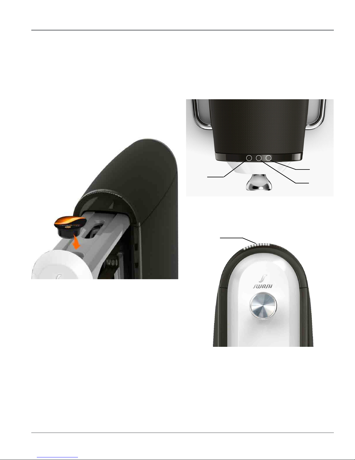
OPERATION
How to Use SWASH™ System
Hang
1. Pull out drawer and hang clothes in machine. See pages
6-7 for more informaon on how to hang clothes.
Load
2. Load a SWASH POD™ cup in top of drawer and close
drawer rmly (see Figure 4). Do not remove lm from cup
as it will get pierced when you push the drawer in. Only
use SWASH PODS™ cups.
Start
3. Select cycle buon to Start. Tap on “10” for standard
cycle, “15” for extended cycle, or “X” to cancel. See page 3
for more informaon.
10
Cancel
15
Figure 5
4. White LEDs will count down the minutes remaining and
a blue light will let you know when the cycle is done (see
Figure 6).
White Lights
(me remaining)
Figure 4
Figure 6
5. Remove the empty SWASH PODS™ cup.
6. Remove garment from SWASH™ system and enjoy.
SWASH™ Clothing Care System
n
2-5

OPERATION
Hanging Clothes
Hanging Your Clothes
Smoothing clips aren’t needed for refreshing. You can get great results with minimal eort. For smoothing wrinkles, try
experimenng with a few clips.
IMPORTANT: The SWASH™ system is not recommend for silk, leather, velvet, suede, and fur. Some temporary spots may occur.
If this happens, clean per clothing manufacturer’s instrucons.
CREASED PANTST-SHIRT / POLO SHIRT
Figure 7
SWEATER DRESS
Figure 8
2-6 n
SWASH™ Clothing Care System

OPERATION
Hanging Clothes (Continued)
Buon Down Shirt
Place sleeves through sleeve wraps and clip. Use the remaining 4 clips to pull at and hold ght to get maximum wrinkle release.
Finally put pocket smoother in pocket.
Pants or Jeans
Hang legs over the top of hanger rst and then clip. Pull waist down and clip
to get the most area exposed to the SWASH PODS™ formula.
Figure 9
Shorts or Skirts
Pull a couple of smoothing clips through the
hanger for shorts and skirts.
Figure 10
SWASH™ Clothing Care System
n
2-7

OPERATION
Emptying the Reservoir
Emptying the Reservoir
The SWASH™ system is designed to collect any excess mist for
easy disposal. If the orange and blue lights are both ashing,
you will need to empty the reservoir that collects the excess
mist.
1. Locate reservoir at rear base of SWASH™ system.
Blue Light
Figure 11
2. Remove reservoir and take to sink (see Figure 12).
Orange Light
3. Pull plug and empty out liquid in sink (see Figure 13).
Figure 13
4. Replace plug and insert reservoir back into SWASH™
system (see Figure 14).
Figure 12
2-8 n
SWASH™ Clothing Care System
Figure 14

Consumer Troubleshooting
Troubleshoong
Nothing happens when you push the 10 or 15
minute button
¾ Check to make sure the SWASH™ system is plugged into a
power outlet.
¾ If SWASH™ system is plugged in, unplug it and plug it back
in to reset.
SWASH™ system does not work as well as expected
¾ Select the recommended cycle based on your clothing type.
¾ Keep longer clothes from laying on the boom of the
device.
¾ SWASH™ system is only recommended for 2 lightweight
items. For best results, refresh only one item at a me.
¾ Do not operate, install, or store the SWASH™ system where
it will be exposed to water, weather, or at temperatures
below 50° F (10° C). Let the SWASH™ system and SWASH
PODS™ cups warm up to room temperature before use.
OPERATION
1. Orange light is blinking - SWASH™ system will
not start
¾ Make sure door is closed properly.
¾ Make sure cup is loaded in bay. If cup is empty or missing,
replace with new cup. Use only SWASH PODS™ cups in your
SWASH™ system.
2. Orange and blue lights are blinking
¾ The reservoir is full and needs to be emped, or is missing
and needs to be replaced. See emptying the reservoir on
page 2-8.
You have a spot on your clothing after a cycle.
¾ The SWASH PODS™ formula may leave a spot on some
fabrics. These spots are easily removed when clothes
are washed or dry-cleaned according to clothing
manufacturer’s care label.
SWASH™ System Tips
Multiple Clothing Items
The SWASH™ system works best on one item. If refreshing
2 items at a me, hang them back-to-back for best results.
Addional SWASH™ hanger required. You can order addional
hangers at SWASH.COM.
Reducing Wrinkles
To maximize wrinkle release, buon or zip up your clothing.
Use the smoothing clips for non-stretchy fabrics. Make sure
your clothes are ght and smooth.
Smoothing Clips
Experiment with the smoothing clips to nd what gives you
the best results for your clothes. You may not need all of the
provided smoothing clips to get great results.
3. Orange and white lights on
¾ If orange and me remaining lights are solid. SWASH™
system is paused. Close door and cycle will resume.
4. Orange light blinking and white lights on
¾ If orange light is blinking and at least two white lights
are solid, SWASH™ system is not working. See Secon 4,
“Diagnoscs and Troubleshoong.”
Temperature Use
If your SWASH™ system or SWASH PODS™ cups have just come
inside from very cold weather, allow them to sit for a while to
get to room temperature before using.
Cleaning SWASH™ system
Use a so, damp cloth or sponge to wipe your SWASH™
system to help keep it looking new.
Wash Hands after Cleaning
If eye contact occurs, rinse well with water. If irritaon
persists, get medical aenon.
Visit swash.com/setup for addional informaon and video demonstraons.
SWASH™ Clothing Care System
n
2-9

OPERATION
Notes
2-10 n
SWASH™ Clothing Care System

COMPONENT ACCESS
Section 3:
Component Access
This secon provides service parts access, removal, and
installaon instrucons for the “SWASH™ Clothing Care
System.”
n SWASH™ System Exploded Views
n SWASH™ System Parts List
n Removing the Rear Panel
n Removing the Top Cover & Control Housing
n Removing the User Interface
n Removing the Dispensing System
n Removing the Pump Assembly
n Removing the Appliance Control Unit (ACU)
n Removing the Thermistor
n Removing the Door Assembly
n Removing the Clips & Roller Assembly
n Removing Base Components
n Removing the Side Panels
n Notes
SWASH™ Clothing Care System
n
3-1

COMPONENT ACCESS
SWASH™ System Exploded View
NOTE: The SWASH™ System Exploded View was not available
at the me of publicaon. Please refer to PartSmartweb
Online Parts Catalog for product related parts informaon.
This page is a place-holder for future revision.
Reference Parts List on page 3
3-2 n
SWASH™ Clothing Care System

COMPONENT ACCESS
SWASH™ System Part List
NOTE: The SWASH™ System Parts List was not available
at the me of publicaon. Please refer to PartSmartweb
Online Parts Catalog for product related parts informaon.
This page is a place-holder for future revision.
SWASH™ Clothing Care System
n
3-3

COMPONENT ACCESS
Removing the Rear Panel
WARNING
Electrical Shock Hazard
Disconnect power before servicing.
Replace all parts and panels before operating.
Failure to do so can result in death or
electrical shock.
1. Unplug the SWASH™ Clothing Care System.
2. Locate the reservoir at the rear base of the unit.
3. Remove the reservoir and set aside.
4. Remove back cover. Using a T-20 TORX driver, remove the
9 screws securing the back cover to the SWASH system
(see Figure 2).
Reservoir
Figure 2
3-4 n
SWASH™ Clothing Care System
Figure 2
5. Set aside back panel for reinstallaon.

Removing the Top Cover & Control Housing
WARNING
Electrical Shock Hazard
Disconnect power before servicing.
Replace all parts and panels before operating.
Failure to do so can result in death or
electrical shock.
1. First, perform procedure on page 3-4, “Removing the Rear
Panel” prior to performing the following steps.
2. Remove the top cover by sliding the cover back “slightly”
towards the rear of the unit (see Figure 1).
COMPONENT ACCESS
4. Using a 1/4” socket, remove the six (6) screws (3 on each
side) securing the control housing to the unit (see Figure 3).
Control Housing
Cover Slots
Figure 3
5. Remove harness shield from back of the control housing
(see Figure 4).
Slide cover towards rear
Figure 1
3. Li the top up and away from the unit—starng from the
back (see Figure 2). Remove cover and set aside.
Li up cover and remove
Harness Shield
Figure 4
6. Remove control housing and set aside (see Figure 5).
Figure 2
Figure 5
SWASH™ Clothing Care System
n
3-5

COMPONENT ACCESS
Removing UI and Dispensing System
WARNING
Electrical Shock Hazard
Disconnect power before servicing.
Replace all parts and panels before operating.
Failure to do so can result in death or
electrical shock.
Removing the User Interface
1. First, perform procedure on page 3-4, “Removing the Rear
Panel” prior to performing the following steps.
2. Next, perform procedure on page 3-5, “Removing Top
Cover and Control Housing.
3. Slide open door.
4. Disconnect harness from UI PCB. See Figure 1.
5. Using a 1/4” nut driver, remove the
securing the User Interface to the control bracket as
illustrated in Figure 1.
door switch and remove from unit.
Pull UI Assembly forward over the
two (2) screws
Removing the Dispensing System
1. First, perform procedure on page 3-4, “Removing the Rear
Panel” prior to performing the following steps.
2. Next, perform procedure on page 3-6, “Removing Top
Cover and Control Housing.
3. Disconnect hose from Dispensing System.
4. Disconnect harness from Dispensing System micro-switch.
See Figure 1.
5. Using a 1/4” nut driver, remove the
securing the Dispensing System to the control bracket as
illustrated in Figure 1.
unit.
Remove Dispensing System from the
Switch Harness
two (2) screws
Pump Hose
Figure 1 - User Interface
Figure 1 - Dispensing System
UI Harness
3-6 n
SWASH™ Clothing Care System

Removing Pump, ACU, and Thermistor
WARNING
Electrical Shock Hazard
Disconnect power before servicing.
Replace all parts and panels before operating.
Failure to do so can result in death or
electrical shock.
Removing the Pump Assembly
1. First, perform procedure on page 3-4, “Removing the Rear
Panel” prior to performing the following steps.
2. Next, perform procedure on page 3-5, “Removing Top
Cover and Control Housing.
3. Disconnect hose from Pump Assembly (see Figure 1).
4. Disconnect hoses from “T” ng (see Figure 1).
5. Disconnect harness from Pump Assembly (see Figure 1).
6. Using a 1/4” nut driver, remove the four (4) screws
securing the Pump Assembly to the control bracket (see
Figure
1).
Remove Pump Assembly from the unit.
“T” Fing Hoses
Pump Hose
COMPONENT ACCESS
Removing the Appliance Control Unit (ACU)
1. First, perform procedure on page 3-4, “Removing the Rear
Panel” prior to performing the following steps.
2. Next, perform procedure on page 3-5, “Removing Top
Cover and Control Housing.
3. Disconnect the four (4) harnesses from the Appliance
Control Unit (ACU).
4. Using a 1/4” nut driver, remove the one (1) screw securing
the ACU to the control bracket (see Figure
ACU from unit.
Figure 1 - ACU
Removing the Thermistor
1. First, perform procedure on page 3-4, “Removing the Rear
Panel” prior to performing the following steps.
2. Next, perform procedure on page 3-5, “Removing Top
Cover and Control Housing.
3. Disconnect the two (2) wires going to the Thermistor
Assembly (see Figure 1).
4. Using a 1/4” nut driver, remove the two (2) screws
securing the Thermistor to the control bracket (see Figure
1).
Remove Thermistor from unit.
1).
Remove
Pump Harness
Figure 1 - Pump Assembly
Thermistor
Wires
Figure 1 - Thermistor
SWASH™ Clothing Care System
n
3-7

COMPONENT ACCESS
Removing the Door Assembly
WARNING
Electrical Shock Hazard
Disconnect power before servicing.
Replace all parts and panels before operating.
Failure to do so can result in death or
electrical shock.
Removing the Door Assembly
1. Unplug the SWASH™ Clothing Care System.
2. Slide open the door assembly as far as possible (see
Figure 1).
3. Lay SWASH™ system on its side to access the boom of
the door assembly (see Figure 2).
4. Separate the lower slide from the door frame. Using a
#2 Phillips screwdriver, remove the
screws and using a #15 TORX driver, remove the four (4)
‘boom-mounted’ screws as illustrated in Figure 2.
Phillips Screws
TORX Screws
Figure 2
NOTE: When reassembling the door frame to the lower slide,
be sure to place the tab of the lower slide assembly into the
slot located under the door frame as shown in Figure 3.
two (2) ‘side-mounted’
Figure 1
Frame Slot
Slide Tab
Figure 3
connued . . .
3-8 n
SWASH™ Clothing Care System

COMPONENT ACCESS
Removing the Clips & Roller Assembly
5. Set SWASH™ system upright. Using a #15 TORX driver,
remove the two (2) screws securing the top door cover as
illustrated in Figure 4. Remove cover to expose the upper
slide assembly.
Phillips Screws
Figure 4
6. Separate the upper slide from the door frame. Using a #1
Phillips screwdriver, remove the
securing the upper door to the slide assembly. See Figure 4.
Door assembly can now be removed from
three (3) bolts and nuts
SWASH™
system.
Removing the Clips & Roller Assembly
1. First, perform procedure on page 3-8, “Removing the Door
Assembly” prior to performing the following steps.
2. Using a #2 Phillips screwdriver, remove the door knob
from door assembly.
3. Remove door cover from door frame. The door cover is
aached to the frame by six (6) clips (see Figure 1). Slowly
pull the door cover from the frame 1 clip at a me starng
from the boom and working to the top.
Figures 1 & 2
4. Remove Clip and Roller Assembly. Using a #2 Phillips
screwdriver, remove the four (4) screws (2 on each side)
securing the clips & roller assembly to the upper door
frame. See Figure 3.
Figure 4
Phillips Screws
(each side)
Figure 3
SWASH™ Clothing Care System
n
3-9

COMPONENT ACCESS
Removing Base Components
WARNING
Electrical Shock Hazard
Disconnect power before servicing.
Replace all parts and panels before operating.
Failure to do so can result in death or
electrical shock.
1. Unplug the SWASH™ Clothing Care System.
2. Locate the reservoir at the rear base of the unit. (Refer to
page 3-4 for locaon of reservoir.)
3. Remove the reservoir and set aside.
4. Lay SWASH™ system on its back (see Figure 1).
5. Using a 1/4” nut driver, remove the ve (5) screws
securing the boom plate to the unit (see Figure 1).
Remove boom plate and set aside.
6. Using a #20 TORX driver, remove the four (4) screws
securing the reservoir housing to the unit (see Figure 2).
Boom Plate
Figure 2
7. Remove the reservoir housing by sliding two at bladed
screwdrivers in-between the housing and side panel of
unit. Gently, move the side panel away from the housing
unl it pops free from base. See Figure 3.
Figure 1
3-10 n
SWASH™ Clothing Care System
Figure 3

Removing Base Components (continued)
8.
Disconnect the blower and heater connectors (see Figure 4).
9. Using a 1/4 nut driver, remove the screw securing the
ground wire coming from the blower motor (see Figure 4).
10. Using a 1/4” nut driver, remove the seven (7) screws
securing the blower/heater assembly to the unit (see
Figure 4).
Blower
Connector
COMPONENT ACCESS
11.
To remove the heater from the blower/heater
assembly, use a 1/4” nut driver to remove the two
screws securing the heater to the blower housing (see
Figure 5 below).
12.
Remove heater assembly from blower housing. The
heater assembly contains the heater coil, thermal
cuto, and high limit thermostat. (See Figure 6.)
Blower Wheel
GND Screw
Figure 6
IMPORTANT: The fan motor and blower wheel cannot be
replaced individually. The fan motor, blower wheel, and
blower housing must be replaced as an assembly.
Heater
Connector
Figure 4
Heater Assembly
Fan Motor
Heater Screws (2)
Figure 5
SWASH™ Clothing Care System
n
3-11

COMPONENT ACCESS
Removing the Side Panels
WARNING
Electrical Shock Hazard
Disconnect power before servicing.
Replace all parts and panels before operating.
Failure to do so can result in death or
electrical shock.
1. First, perform procedure on page 3-6, “Removing the Rear
Panel” prior to performing the following steps.
2. Next, perform steps 1 - 3 on page 3-7, “Removing Top
Cover and Control Housing.
3. Side panels are held in place with tabs (see Figure 2). To
remove side panel, grasp top of panel on each side and li
up (see Figure 1). Set aside for reassembly.
Side Panel Tabs (4)
Li up panel and remove
Figure 2
5. SWASH™ system with side panels removed (see Figure 4).
NOTE: Two (2) sprayers on each side of cabinet.
Sprayers
Tabs Slots (4)
Figure 1
4. Repeat process for other side.
3-12 n
SWASH™ Clothing Care System
Figure 3

Notes
COMPONENT ACCESS
SWASH™ Clothing Care System
n
3-13

COMPONENT ACCESS
Notes
3-14 n
SWASH™ Clothing Care System

DIAGNOSTICS & TROUBLESHOOTING
Section 4:
Diagnostics &
Troubleshooting
This secon provides diagnosc, fault codes, and
troubleshoong informaon for the “SWASH™ Clothing Care
System.”
n Safety First
n Customer Troubleshoong
n Customer Error Codes
n Control Panel
n Diagnosc Guide
n Service Diagnoscs
n Service Diagnosc Funcons
n Fault / Error Codes
n Troubleshoong Guide
n Wiring Diagram
n Appliance Control Unit (ACU)
n User Interface (UI) Assembly
n Strip Circuits
n Notes
SWASH™ Clothing Care System
n
4-1

DIAGNOSTICS & TROUBLESHOOTING
WARNING
For Service Technician Use Only
DANGER
Electrical Shock Hazard
Only authorized technicians should perform
diagnostic voltage measurements.
After performing voltage measurements,
disconnect power before servicing.
Failure to follow these instructions can result in
death or electrical shock.
Disconnect power before servicing.
Replace all parts and panels before operating.
Failure to do so can result in death or
electrical shock.
Electrical Shock Hazard
Voltage Measurement Safety Information
When performing live voltage measurements, you must do the following:
n Verify the controls are in the off position so that the appliance does not start when energized.
n Allow enough space to perform the voltage measurements without obstructions.
n Keep other people a safe distance away from the appliance to prevent potential injury.
n Always use the proper testing equipment.
n After voltage measurements, always disconnect power before servicing.
IMPORTANT: Electrostatic Discharge (ESD) Sensitive Electronics
ESD problems are present everywhere. Most people begin to feel an ESD discharge at approximately
3000V. It takes as little as 10V to destroy, damage, or weaken the main control assembly. The new
main control assembly may appear to work well after repair is nished, but a malfunction may occur
at a later date due to ESD stress.
n Use an anti-static wrist strap. Connect wrist strap to green ground connection point or unpainted
metal in the appliance
n Touch your nger repeatedly to a green ground connection point or unpainted metal in the
appliance.
n Before removing the part from its package, touch the anti-static bag to a green ground
connection point or unpainted metal in the appliance.
n Avoid touching electronic parts or terminal contacts; handle electronic control assembly by
edges only.
n When repackaging main control assembly in anti-static bag, observe above instructions.
IMPORTANT SAFETY NOTICE — “For Technicians only”
This service data sheet is intended for use by persons having electrical, electronic, and mechanical
experience and knowledge at a level generally considered acceptable in the appliance repair trade.
Any attempt to repair a major appliance may result in personal injury and property damage. The
manufacturer or seller cannot be responsible, nor assume any liability for injury or damage of any
kind arising from the use of this data sheet.
4-2 n
SWASH™ Clothing Care System
-OR-

DIAGNOSTICS & TROUBLESHOOTING
For Service Technician Use Only
Customer Troubleshoong
Nothing happens when you push the 10 or 15
minute button
¾ Check to make sure the SWASH™ system is plugged into a
power outlet.
¾ If SWASH™ system is plugged in, unplug it and plug it back
in to reset.
SWASH™ system does not work as well as expected
¾ Select the recommended cycle based on your clothing type.
¾ Keep longer clothes from laying on the boom of the
device.
¾ SWASH™ system is only recommended for 2 lightweight
items. For best results, refresh only one item at a me.
¾ Do not operate, install, or store the SWASH™ system where
it will be exposed to water, weather, or at temperatures
below 50° F (10° C). Let the SWASH™ system and SWASH
PODS™ cups warm up to room temperature before use.
You have a spot on your clothing after a cycle.
¾ The SWASH PODS™ formula may leave a spot on some
fabrics. These spots are easily removed when clothes
are washed or dry-cleaned according to clothing
manufacturer’s care label.
Customer Error Codes
1. Orange light is blinking - SWASH™ system will
not start
¾ Make sure door is closed properly.
¾ Make sure cup is loaded in bay. If cup is empty or missing,
replace with new cup. Use only SWASH PODS™ cups in your
SWASH™ system.
2. Orange and blue lights are blinking
¾ The reservoir is full and needs to be emped, or is missing
and needs to be replaced. See emptying the reservoir on
page 2-8.
3. Orange and white lights on
¾ If orange and me remaining lights are solid. SWASH™
system is paused. Close door and cycle will resume.
4. Orange light blinking and white lights on
¾ If orange light is blinking and at least two white lights
are solid, SWASH™ system is not working. See Secon 4,
“Diagnoscs and Troubleshoong.”
SWASH™ Clothing Care System
n
4-3

DIAGNOSTICS & TROUBLESHOOTING
FOR SERVICE TECHNICIAN’S USE ONLY
For Service Technician Use Only
Control Panel
White LEDs (15)
X
“10” key
10 15
“X” key
Control Panel, Viewed From Above Control Panel, Viewed From Front
“15” key
Diagnosc Guide
Before servicing, check the following:
n Make sure there is power at the wall outlet.
n Has a household fuse blown or circuit breaker tripped? Was a
regular fuse used? Inform the customer that a me delay fuse
is required.
n All tests/checks should be made with a VOM (volt-ohm-
milliammeter) or DVM (digital-voltmeter) having a sensivity
of 20,000 Ω per volt DC or greater.
n Check all connecons before replacing components. Look for
broken or loose wires, failed terminals, or wires not pressed
into connecons far enough.
n A potenal cause of a control not funconing is corrosion on
connecons. Observe connecons and check for connuity
with an ohmmeter.
n Connectors: Look at top of connector. Check for broken or
loose wires. Check for wires not pressed into connector far
enough to engage metal barbs.
n Resistance checks must be made with power cord unplugged
from outlet, and with wiring harness or connectors
disconnected.
Blue LED
LED 8
LED 6
LED4
Figure 1
LED 10
LED 12
LED 14
Service Diagnoscs
NOTE: THE ONLY WAY TO ENTER SERVICE DIAGNOSTICS IS
FROM THE OFF MODE.
The SWASH™ system should be able to enter service
diagnoscs mode regardless of the state of door switch and
reservoir switch.
Right aer powering up (plugging in the SWASH™ system), you
will have 30 seconds to press the three dierent keys in any
sequence three mes within 10 seconds to place the SWASH™
system in service diagnosc mode. If the key sequence is not
completed within the 10 second me period, entrance to
service diagnosc mode will not occur. If entrance to service
diagnosc mode is successful, the following sequence of
events will occur:
1. If the reservoir switch is ON, all 15 white LEDs will ash
ON and OFF. The tester must verify that no LED is missing.
If the reservoir switch is OFF, all 15 White LEDs will be OFF.
2. The service technician will instruct the tester to “Press
and hold the <15> key”. If the tester veries that the fan
relay turned ON, this step passed. Releasing the <15> key
will turn the relay OFF.
3. Next the service technician will instruct the tester to
“Press and hold the <10> key”. If the tester veries that
the pump relay turned ON by detecng a waage change
of approximately 60W, this step passed. Releasing the
<10> key will turn the relay OFF. Verify that the power
consumpon decreased.
4. Next the service technician will instruct the tester to
“Press and hold the <X> key”. If the tester veries that
the heater reads approximately 1300W, this step passed.
Releasing the <X> key will turn the relay OFF.
5. The blue LED will ash ON and OFF if the thermistor is
operang correctly.
6. The blue LED will turn ON if the thermistor is OPEN or
SHORTED.
7. Open the door and the orange LED will turn OFF.
8. Shut the door and the orange LED will ash ON and OFF.
9. Service diagnoscs will end aer two minutes or if power
is cycled.
Orange LED
4-4 n
SWASH™ Clothing Care System
NOTE: Refer to table on page 4-5 for diagnosc test funcons.

DIAGNOSTICS & TROUBLESHOOTING
For Service Technician Use Only
Service Diagnosc Funcons (see page 4-4 for instrucons)
Right aer powering up (plugging in the SWASH™ system), you will have 30 seconds to press the three dierent keys in any
sequence three mes within 10 seconds to place the SWASH™ system in service diagnosc mode. If entrance to service
diagnosc mode is successful, the following funcons will be available.
COMPONENT KEY STATUS LEDs
RESERVOIR SWITCH ON
OFF
FAN RELAY “15” Acvates Fan* N/A
All 15 White LEDs ash ON and OFF
All 15 White LEDs OFF
PUMP RELAY “10”
HEATER RELAY “X”
THERMISTOR Funconal
DOOR SWITCH Open
NOTES:
* Press and hold the <15> key to turn on the Fan. Release the <15> key to turn o the Fan.
† Press and hold the <10> key to turn on the Pump. Release the <10> key to turn o the Pump.
‡ Press and hold the <X> key to turn on the Heater. Release the <X> key to turn o the Heater. (You will hear the heater
solenoid on the ACU “click” when the heater turns on and o.)
Acvates Pump†
Acvates Heater‡
Open/Shorted
Closed
N/A
N/A
Blue LED Flash ON and OFF
Blue LED will turn ON
Orange LED will turn OFF
Orange LED Flash ON and OFF
SWASH™ Clothing Care System
n
4-5

DIAGNOSTICS & TROUBLESHOOTING
For Service Technician Use Only
Fault / Error Codes
DISPLAY ERROR CODE MALFUNCTION EXPLANATION AND RECOMMENDED PROCEDURE
LED ON:
12, 14
LED FLASHING:
ORANGE
LED ON:
10, 12, 14
LED FLASHING:
ORANGE
LED ON:
8, 10, 12, 14
LED FLASHING:
ORANGE
F3E1 Open Thermistor Condion Connually monitor temperature sensor for an invalid
resistance value based on the thermistor reading value out
of the range of 35.42kΩ (32°F/0°C) and 719Ω (212°F/100°C).
This error will show if reading more than 35.42kΩ for more
than 30 seconds.
1. Review the ambient temperature of the room; if the
temperature of the sensor is less than 32°F (0°C), the
error will remain.
2. Verify the wire harness connecon. Any open
connecon will create a resistance higher than 35.42kΩ
and the error will remain.
3. Reset the ACU by unplugging the SWASH™ system for
more than 5 seconds.
4. Enter the service diagnoscs mode (see page 2) and
review the operaon of the thermistor.
5. Verify the resistance value of the thermistor (J3-5 to J3-
6); if it is open or shorted, replace the thermistor.
F2E2 Shorted Thermistor Condion Connually monitor temperature sensor for an invalid
resistance value based on the thermistor reading value out
of the range of 35.42kΩ (32°F/0°C) and 719Ω (212°F/100°C).
This error will show if reading less than 719Ω for more than
30 seconds.
1. Review the ambient temperature of the room; if the
temperature of the sensor is more than 212°F (100°C),
the error will remain.
2. Verify the wire harness connecon. Any shorted
connecon will create a resistance lower than 719Ω
and the error will remain.
3. Reset the ACU by unplugging the SWASH™ system for
more than 5 seconds.
4. Enter the service diagnoscs mode (see page 2) and
review the operaon of the thermistor.
5. Verify the resistance value of the thermistor (J3-5 to J3-
6); if it is open or shorted, replace the thermistor.
F2E1 Shorted Key Event If the control detects an invalid key press (one or more keys
pressed for more than 5 seconds), the UI will generate an
error code (F2E1) to the ACU.
1. Disconnect the WIDE Connector of the UI and reset the
SWASH™ system by unplugging the power for more
than 5 seconds. By doing this, the capacive buons
will recalibrate.
2. Make sure that the UI PCB Assembly is not aected by
extreme ambient condions like temperature (185°F
[85°C] max.) and humidity (95% non condensate).
3. Verify 5V input from WIDE connector between lines
P1-1 and P3-1.
4. Inspect the keypad area to conrm that there are no
liquids, moisture, or any other foreign materials on the
capacive buon area.
4-6 n
SWASH™ Clothing Care System
Connued . . .

DIAGNOSTICS & TROUBLESHOOTING
For Service Technician Use Only
Fault / Error Codes (connued)
DISPLAY ERROR CODE MALFUNCTION EXPLANATION AND RECOMMENDED PROCEDURE
LED ON:
6, 8, 10, 12, 14
LED FLASHING:
ORANGE
LED ON:
4, 6, 8, 10, 12, 14
LED FLASHING:
ORANGE
F6E1 WIDE Communicaon The failure will be shown if: Communicaon
• The ACU has not received a valid WIDE serial
communicaon message within 30 seconds.
• The ACU has detected connuous problems with
messages transmied over the WIDE bus.
• If communicaon is resumed at any me, the display
will funcon normally.
1. Check the wire harness connecon between the ACU
and the UI, and measure connuity between all wires.
2. Make sure that the UI PCB Assembly and the ACU
board are not aected by extreme ambient condions
like temperature (185°F [85°C] max.) and humidity
(95% non condensate).
3. Reset the SWASH™ system by disconnecng the power
for more than 5 seconds.
4. Verify 5V output from the WIDE connector between
lines P1-1 and P3-1 and the P19 connector.
5. Enter the service diagnoscs mode (see page 2) and
review the operaon of the thermistor.
F1E1 Microcontroller Fault If a corrupted microcontroller or communicaon error has
occurred, the ACU will generate this error code.
1. Review input voltage from lines P12 and P9. It should
be 120 VAC/60 Hz.
2. Make sure that the ACU board is not aected by
extreme ambient condions like temperature (185°F
[85°C] max.) and humidity (95% non condensate).
3. Remove the ACU board from the plasc chassis and
perform a visual inspecon of the back of the board.
4. Verify 5V and 12V output on the P19 connector
between pins P19-2 and P19-3 for 5V, and P19-1 and
P19-3 for 12V.
5. If no voltage is detected in step 4, replace the ACU.
SWASH™ Clothing Care System
n
4-7

DIAGNOSTICS & TROUBLESHOOTING
WARNING
For Service Technician Use Only
Troubleshoong Guide
DANGER
Electrical Shock Hazard
Only authorized technicians should perform
diagnostic voltage measurements.
After performing voltage measurements,
disconnect power before servicing.
Failure to follow these instructions can result in
death or electrical shock.
Disconnect power before servicing.
Replace all parts and panels before operating.
Failure to do so can result in death or
electrical shock.
PROBLEM POSSIBLE CAUSE /TEST
NOTE: Possible Causes/Tests must be performed in the sequence show for each problem.
WON’T POWER UP
(buons do not respond
when pressed)
WON’T START A CYCLE 1. Verify that there is a cup inside the SWASH™ system.
WON’T DISPENSE 1. Verify that the cup inside the SWASH™ system is new.
1. Verify that the SWASH™ system is plugged into a working outlet and that there are no blown fuses or
tripped circuit breakers.
2. Verify that the plug does not have two adapters aached to it.
3. Unplug the SWASH™ system or disconnect the power.
4. Reconnect the power.
5. Check the voltage available (120V) at the ACU terminals (CON2-P12 and CON1-P9). If there is voltage,
go to step 10.
6. If there is no voltage at the ACU, disconnect the power cord from the harness and check if there is
voltage (120V) at the connector that plugs into the harness. If there is voltage at the power cord
connector, go to step 8.
7. Replace the power cord if there is no voltage at the connector.
8. Check the connuity between power cord connector terminal 1 on the harness and CON2-P12. Check
the connuity between terminal 2 and CON1-P9.
9. Replace the harness if there is no connuity in any line.
10. Check that there is 5V DC between pin 2 and pin 3 at connector P19 inside the ACU.
11. If there is no voltage between pin 2 and pin 3 at connector P19 on the ACU, replace the ACU.
12. If there is voltage between pin 2 and pin 3 at connector P19 on the ACU, replace the UI.
2. Check if the orange LED on the UI is ashing at a rate of 3 Hz.
3. If the orange LED is ashing and a cup is inserted in the SWASH™ system, verify that the piercing
mechanism is funconing properly.
4. Verify that the pump harness is connected to the ACU at connector J1-10.
5. Disconnect the pump, aempt to start a cycle, and verify that there is voltage at the pump terminals
on the harness during the dispensing phase.
6. If there is no voltage at the pump terminals on the harness, check the connuity of the harness
between the pump and the ACU. If connuity is OK, replace the ACU.
2. Disconnect the pump, aempt to start a cycle, and verify that there is voltage at the pump terminals
on the harness during the dispensing phase. If there is voltage, go to step 4.
3. If there is no voltage at the pump terminals on the harness, check the connuity of the harness
between the pump and the ACU. If connuity is OK, replace the ACU.
4. If there is voltage at the pump terminals on the harness, replace the pump.
Electrical Shock Hazard
4-8 n
SWASH™ Clothing Care System
Connued . . .

DIAGNOSTICS & TROUBLESHOOTING
For Service Technician Use Only
Troubleshoong Guide (connued)
PROBLEM POSSIBLE CAUSE /TEST
NOTE: Possible Causes/Tests must be performed in the sequence show for each problem.
GARMENT IS WET 1. Disconnect the fan motor and verify that there is voltage of 120V at the fan motor connector on the
THERE IS A PUDDLE OF
WATER BENEATH THE
SWASH™ SYSTEM
CUP IS NOT COMPLETELY
EMPTY
SWASH™ SYSTEM STARTS
BY ITSELF
SWASH™ SYSTEM VIBRATES
OR IS NOISY
harness during the running/drying mode. If there is voltage, go to step 5.
2 If there is no voltage at the fan motor connector on the harness, check the connuity between fan
motor connector terminal 1 and CON1-P11 and also between fan motor connector terminal 2 and
CON1-P9.
3. Replace the harness if there is no connuity in any line.
4. Replace the ACU if the harness is OK and if voltage was not found at the fan motor connector on the
harness in step 1.
5. If there is voltage at the fan motor connector on the harness, replace the fan motor.
1. Empty the reservoir tray.
2. Disconnect the reservoir sensor switch.
3. Check the connuity (J3-3 to J3-4) in the reservoir sensor switch connector to the SWASH™system
when the reservoir tray is inserted. If there is connuity, go to step 5.
4. If there is no connuity, replace the reservoir sensor switch.
5. Check the connuity in the harness between reservoir sensor switch connector terminal 1 and
CON3-P4 and also between sensor switch connector terminal 2 and CON3-P3.
6. Replace the harness if there is no connuity in any line.
7. If none of these steps indicate an electrical problem, the problem is mechanical and the reservoir tray
must be replaced.
1. Verify that the piercing mechanism is properly piercing the cup.
2. Remove the needle and make sure that liquid can pass through it.
3. Inspect the hoses to verify that they are not kinked.
4. Replace the pump.
1. Check for an error code on the SWASH™ system display.
2. Verify that there is voltage of 5V DC between pin 2 and pin 3 at connector P19 on the ACU.
3. If there is no voltage between pin 2 and pin 3 at connector P19 on the ACU, replace the ACU.
4. If there is voltage between pin 2 and pin 3 at connector P19 on the ACU, replace the UI.
1. Verify that the pump is properly aached.
2. Make sure that the impeller is not touching the lower blower.
3. Verify that the motor is properly aached.
4. Verify that the motor sha is not damaged.
SWASH™ Clothing Care System
n
4-9

DIAGNOSTICS & TROUBLESHOOTING
FOR SERVICE TECHNICIAN’S USE ONLY
For Service Technician Use Only
CUP
SWITCH
SENSOR
IMPORTANT: Electrostac discharge may cause damage to control electronics. See page 5-1 for ESD informaon.
Figure 2
Wiring Diagram
4-10 n
SWASH™ Clothing Care System

For Service Technician Use Only
Appliance Control Unit (ACU)
DIAGNOSTICS & TROUBLESHOOTING
J3 - Thermistor, Cup &
Reservoir Switches
J1 - Neutral, Pump, & Fan Motor
APPLIANCE
CONTROL
UNIT
ACU CONNECTOR PIN-OUTS
CONNECTOR J1
(Neutral, Pump, and Fan Motor)
J1-9 Neutral from plug
J1-10 Pump
J1-11 Fan Motor
CONNECTOR J2
(L1 and Heater)
J2-7 Heater Assembly
J2-12 L1 from plug
P19 - User Interface J2 - L1 & Heater
Figure 3
CONNECTOR J3
(Pod Switch, Reservoir Switch, and Thermistor)
J3-2 Switch, Cup Sensor
J3-3 Switch, Reservoir Sensor
J3-4 Switch, GND
J3-5 Thermistor (Temp 2)
J3-6 Thermistor (Temp 1)
CONNECTOR P19
(User Interface)
P19-2 +5 VDC
P19-3 Ref GND
P19-4 DATA
SWASH™ Clothing Care System
n
4-11

DIAGNOSTICS & TROUBLESHOOTING
For Service Technician Use Only
User Interface (UI) Assembly
Figure 3 - User Interface Assembly
Flex PCB
Rigid PCB
P3 - Flex PCB
UI CONNECTOR PIN-OUTS
CONNECTOR J1
(Appliance Control Unit)
J1-1 +5 VDC
J1-2 DATA
J1-3 Ref GND
User Interface
Rigid PCB
J1 - Appliance Control Unit
Figure 3 - Rigid PCB
CONNECTOR P3
(Flex PCB)
P3 - Ribbon Connector
4-12 n
SWASH™ Clothing Care System

Strip Circuits
L1
N
FAN MOTOR
L1
N
HEATER
L1
N
PUMP
Heater
DIAGNOSTICS & TROUBLESHOOTING
For Service Technician Use Only
BK
Fan Motor
Pump
J2-12
ACU BOARD
BK
BK
J2-12
HEATER
J2-12
RELAY
J2-7
ACU BOARD
FAN MOTOR
RELAY
ACU BOARD
PUMP
RELAY
V
P6-1
J1-11
J1-10
THERMAL
CUTOFF
BOTTOM TRAY
NOTE: Check TCO & High Limit if open circuit is detected.
THERMAL
FUSE
LBU
P7-1
BOTTOM TRAY
NOTE: Check Thermal Fuse if open circuit is detected.
HEATER
ELEMENT
11.5 Ω
FAN
MOTOR
13.1 Ω
M
PUMP
V
P5-1
NOTE: Check pump resistance if open circuit is detected.
??? Ω
P
P5-2
HIGH LIMIT
THERMOSTAT
W
P7-2
W
P6-2
W
W
W
W
Pod / Reservoir Switches
CUP SENSOR SWITCH
POD SENSOR SWITCH
RESERVOIR SENSOR SWITCH
ACU BOARD
Thermistor
ACU BOARD
TEMP1
J3-6
POD SWITCH
CUP SWITCH
J3-2
J3-3
B
Y
RESERVOIR
SWITCH
THERMISTOR
R/W R/W
10k Ω ∗
* Approximate value measured
at room temperature
R
J3-4
R
GND
ACU BOARD
ACU BOARD
J3-5
TEMP 2
SWASH™ Clothing Care System
4-13
n

DIAGNOSTICS & TROUBLESHOOTING
Notes
4-14 n
SWASH™ Clothing Care System

PRODUCT SPECIFICATIONS &
WARRANTY INFORMATION SOURCES
IN THE UNITED STATES:
FOR PRODUCT SPECIFICATIONS AND WARRANTY INFORMATION CALL:
PHONE: 1-866-333-4195
FOR TECHNICAL ASSISTANCE WHILE AT THE CUSTOMER’S HOME CALL:
THE TECHNICAL ASSISTANCE LINE: 1-800-832-7174
HAVE YOUR STORE NUMBER READY TO IDENTIFY YOU AS AN
AUTHORIZED IN-HOME SERVICE PROFESSIONAL
FOR LITERATURE ORDERS (CUSTOMER EXPERIENCE CENTER):
PHONE: 1-800-851-4605
FOR TECHNICAL INFORMATION AND SERVICE POINTERS:
www.servicemaers.com
IN CANADA:
FOR PRODUCT SPECIFICATIONS AND WARRANTY INFORMATION CALL
PHONE: 1-800-461-5681
FOR TECHNICAL ASSISTANCE WHILE AT THE CUSTOMER’S HOME CALL:
THE TECHNICAL ASSISTANCE LINE: 1-800-488-4791
HAVE YOUR STORE NUMBER READY TO IDENTIFY YOU AS AN
AUTHORIZED IN-HOME SERVICE PROFESSIONAL

SWASH™
Clothing Care System
W10713431
 Loading...