

Page 1
1
QHW_ALARMCD290914E | © Swann 2014
Alarm Security Kit - NVR EN
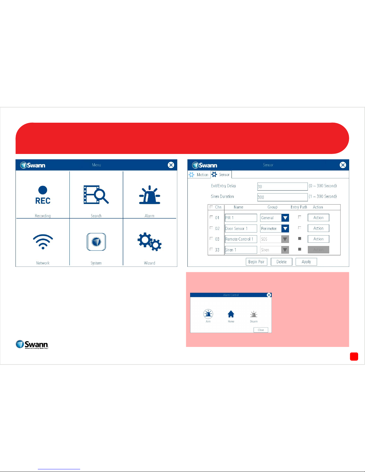
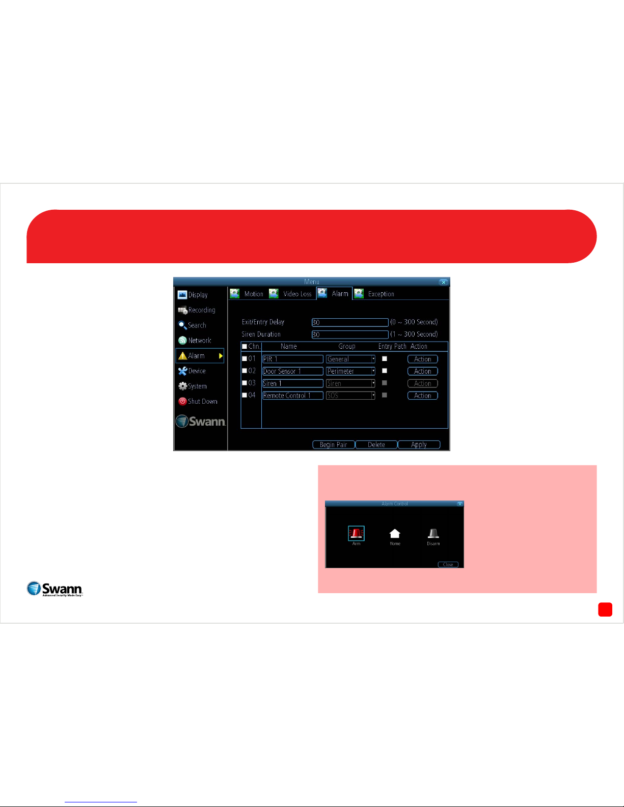
The alarm configuration menu (see above right screenshot) allows you
to configure and change settings for the PIR movement sensors, window/door sensors, remote controls (key fobs) and wireless siren.
All movement sensors, window/door sensors, remote controls and wireless siren are paired with your USB antenna during manufacture however, pairing instructions are provided in case you have to restore your
NVR to default settings as per the instructions in this quick start guide.
Please download the full user manual for a comprehensive explanation
of the various functions available (www.swann.com).
To access the “Alarm Control” menu, right-click the mouse at the
Live View screen to access the Menu Bar, then click the “Alarm” icon.
The alarm control function allows you to enable all alarms
(Arm), a perimeter alarm
(Home) or to disable the alarm
(Disarm). You can also use the
remote control to enable or
disable the same functions.
Page 2
42
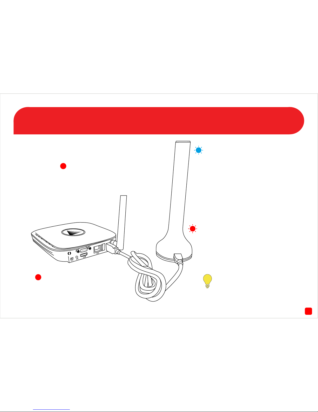
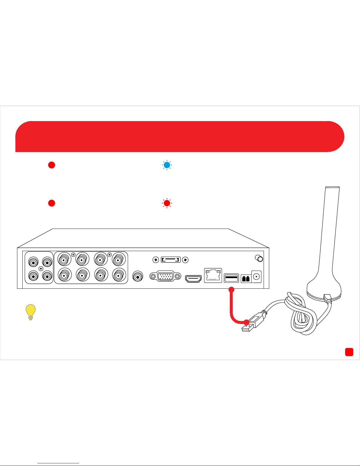
Connecting the USB Antenna
Connect the mini-USB connection on the
provided USB cable to the mini-USB port
on the USB antenna. Connect the other
end to a spare USB port at the rear of the
NVR.
When the USB antenna is connected to
the NVR you will see a blue LED at the top
and bottom.
If the NVR hasn’t detected the USB
antenna, you will see “Motion” at
the Main Menu instead of “Alarm”.
Make sure the antenna is connected
correctly then restart the NVR.
The top and bottom LED will flash blue
to indicate the USB antenna is initialising.
The LED will stop flashing when the
antenna is ready.
The bottom LED will flash red when the
wireless siren has been triggered.
Page 3
73
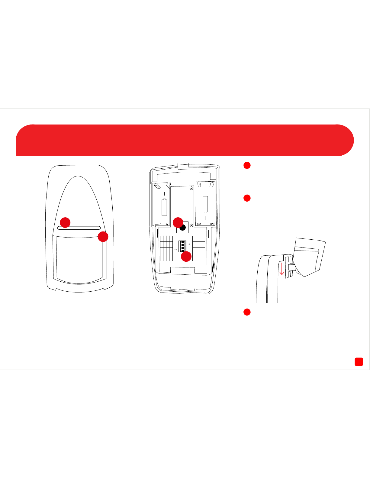
The PIR Movement Sensor
1. LED - Will flash red to indicate
that movement has been
detected.
2. PIR Sensor - Is an electronic
sensor that can detect warm
moving objects in its field of view.
1234
ON
OFF
1 2 MODE
ON OFF 1-pulse
OFF ON 2-pulse
OFF ON 3-pulse
3 4 MODE
ON OFF TEST
OFF ON NORMAL
OFF ON CODING
1
2
3
4
3. Tamper Button - If the back
cover has been removed, an alert
will be sent to the NVR.
4. DIP Switches - Do not adjust
these as they have been set
correctly during manufacture.
Using a flathead screwdriver, insert this into the clip at the bottom
of the movement sensor to open
the back cover.
Install the provided 3V battery into
the battery compartment. Put the
cover back on when you have
finished and follow the pairing
instructions on page 6.
Insert the mounting bracket at
the top of the movement sensor.
Push down until it clicks into place
as illustrated above.
Page 4
24
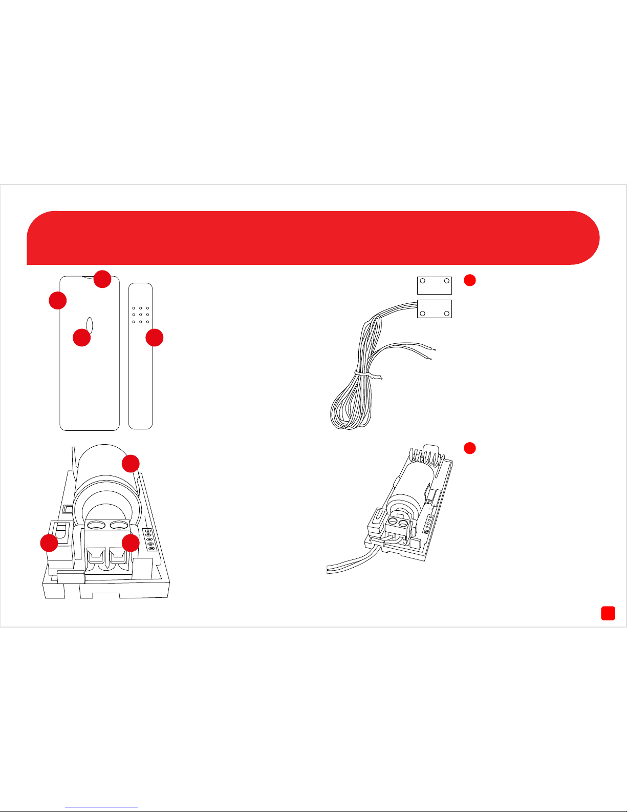
The Window/Door Sensor
1. Window/Door Sensor.
2. Using a flathead screwdriver, gen-
tly press down the button at the top
and use a downward motion to open
the cover.
3. The LED will flash green during
normal operation. You will momentarily see a solid green LED
when the sensor has been activated.
4. The width between the magnet
sensor and window/door sensor
should be no more than half an
inch (1.25 cm) apart.
5. Install the provided 3V battery into
the battery compartment. A green
LED will start to flash.
6. The pair/tamper button pairs
the window/door sensor to your
NVR. Follow the pairing instructions on page 7.
7. The wired sensor connects
here. Please note, the wired door
sensor is an optional installation.
1
2
3 4
5
6 7
Thread the wired sensor cable
into the window/door sensor
(see below illustration). Use
a Phillips head screwdriver
to tighten the cable into the
terminal.
The wired sensor can be used
if you have double windows
or doors within the house or
if you have a sliding door that
has a corresponding security
door. Put the cover back on
after pairing.
Page 5
5
The Wireless Siren
Fig. 1 - Use a Phillips head
screwdriver to remove the
battery cover. Install 3 x AA
batteries provided. Put the
cover back on when you
have finished and fasten the
screw.
Fig. 2 - To access the pair
button, use a Phillips head
screwdriver to remove three
screws as illustrated on the
left. Carefully remove the
cover and try to minimise
any contact with the internal
components.
Fig. 3 - The pair button is
located on the right and the
green and blue LEDs are located at the bottom. Follow
the pairing instructions on
page 8. Put the cover back on
after pairing and fasten all
three screws.
Fig. 4 - Use the mounting
bracket to install the wireless siren to a wall or ceiling.
Please note, there is a tab on
the back of the siren which
locks in with the groove on
the mounting bracket. Slide
the siren to the right to lock
it in place.
Bracket Mount
Page 6
86
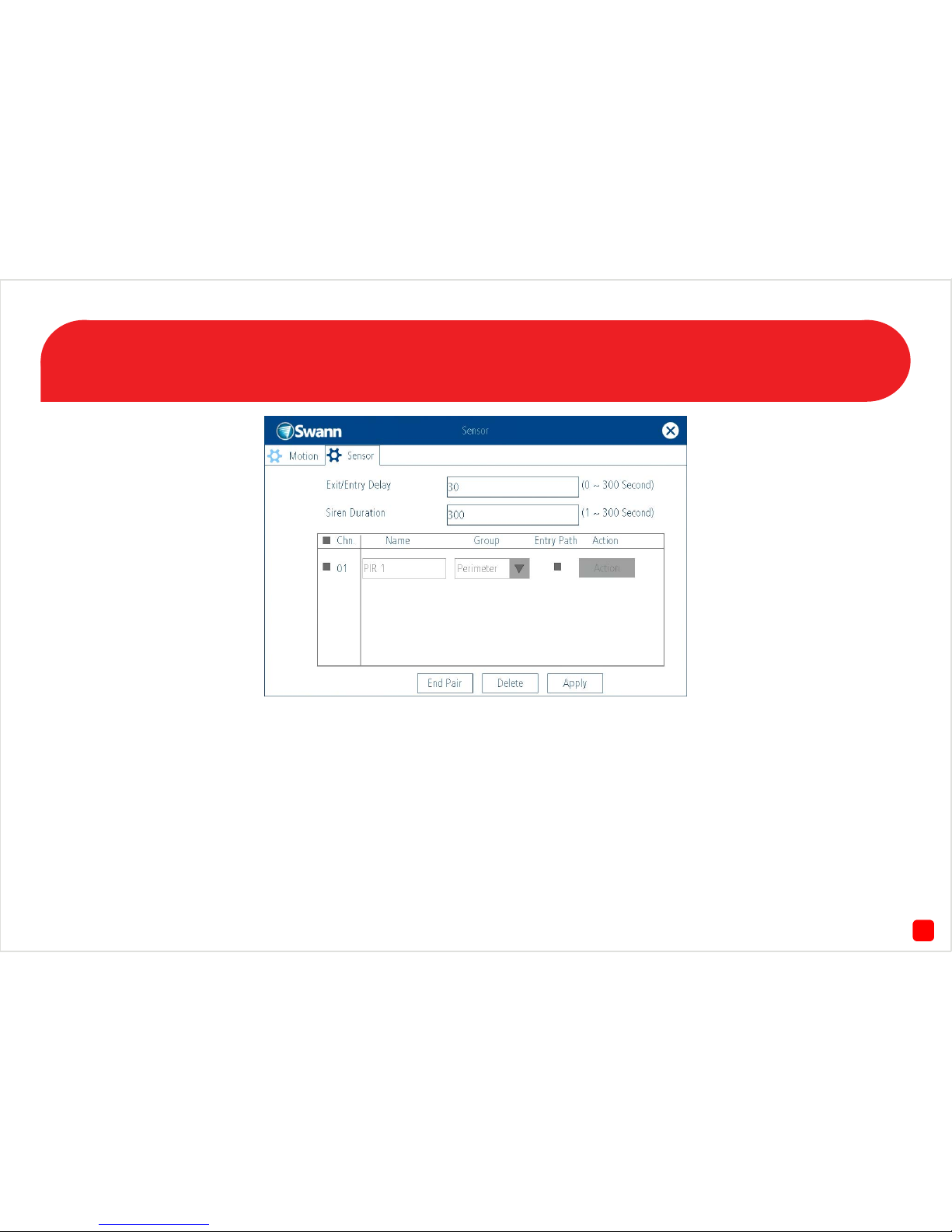
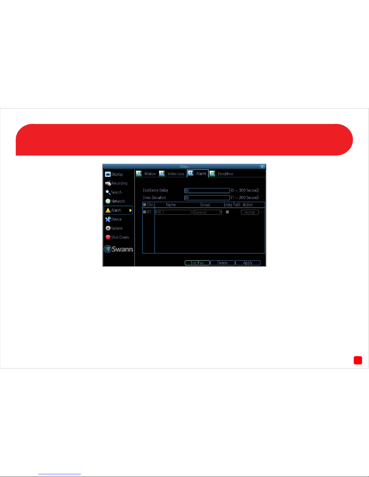
Pairing the PIR Movement Sensors
1. To access the “Sensor” menu, right-click the mouse at the Live View
screen, click “Menu”, click “Alarm” then click the “Sensor” tab.
2. Click “Begin Pair”.
3. Activate the movement sensor by moving in front of it. The LED will
flash red and the NVR will detect the sensor and add it to the sensor list.
Repeat this step for any other movement sensors.
Please note, to conserve battery power, the PIR movement sensor when
activated will wait five seconds to activate again.
Group - There are three options available to group your sensors. For
the PIR movement sensor it is recommended that you set this to “General”. This means any movement within the vicinity of the sensor will
then activate the wireless siren to be activated when you select “Arm”
in the “Alarm Control” menu. You can change this group when you have
finished pairing.
Page 7

37
Pairing the Window/Door Sensors
1. If the window/door sensor has the cover on, follow the instructions on
page 4 to gain access to the pair/tamper button.
2. Press and hold the pair/tamper button. You will momentarily see a
flashing red LED then a solid green LED.
3. The NVR will detect the sensor and add it to the sensor list. Repeat
this step for any other window/door sensors. Put the cover back on when
you have finished.
It’s a good idea to make sure the window/door sensor and the magnetic
sensor are held together to prevent it from triggering.
Group - Leave this as “Perimeter”. The perimeter group allows move-
ment inside the house (when you select “Home” in the “Alarm Control”
menu) but if a window or door is opened this will activate the siren.
Page 8
68
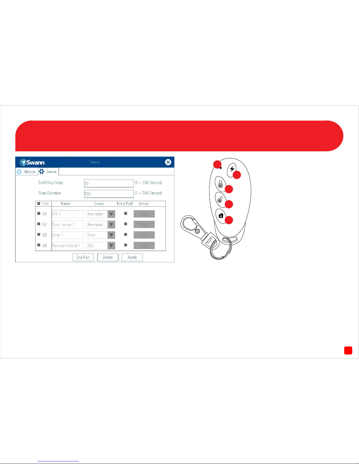
Pairing the Wireless Siren/Remote Control
1. Press and hold the pair button on the wireless siren (see page 5 - Fig.
3). After a short moment you will see a solid blue LED. The NVR will
detect the siren and add it to the sensor list. Put the cover back on after
pairing and fasten all three screws.
2. The battery for the remote control is pre-installed so there is no need
to open the battery cover located at the rear.
3. Press one of the buttons on the remote control. The NVR will detect
the remote control and add it to the sensor list. Repeat this step if you
have more than one remote control.
4. Click “End Pair” then click “Apply”.
Group - The remote control is always set to “SOS” and cannot be
changed.
Don’t forget to click “Apply” otherwise any changes made will not be
saved.
1) Transmit LED - If you don’t see
a red LED when you press a button,
this indicates the battery is flat.
2) Panic - Click this to activate the
wireless siren instantly.
3) Alarm On - Click this to enable all
sensors listed in the sensor list.
4) Alarm Off - Click this to disable all
sensors listed in the sensor list.
5) Perimeter On - Click this to enable
all window/door sensors only. This
allows movement inside the house
but if a window or door is opened this
will activate the wireless siren.
2
3
4
5
1
Page 9
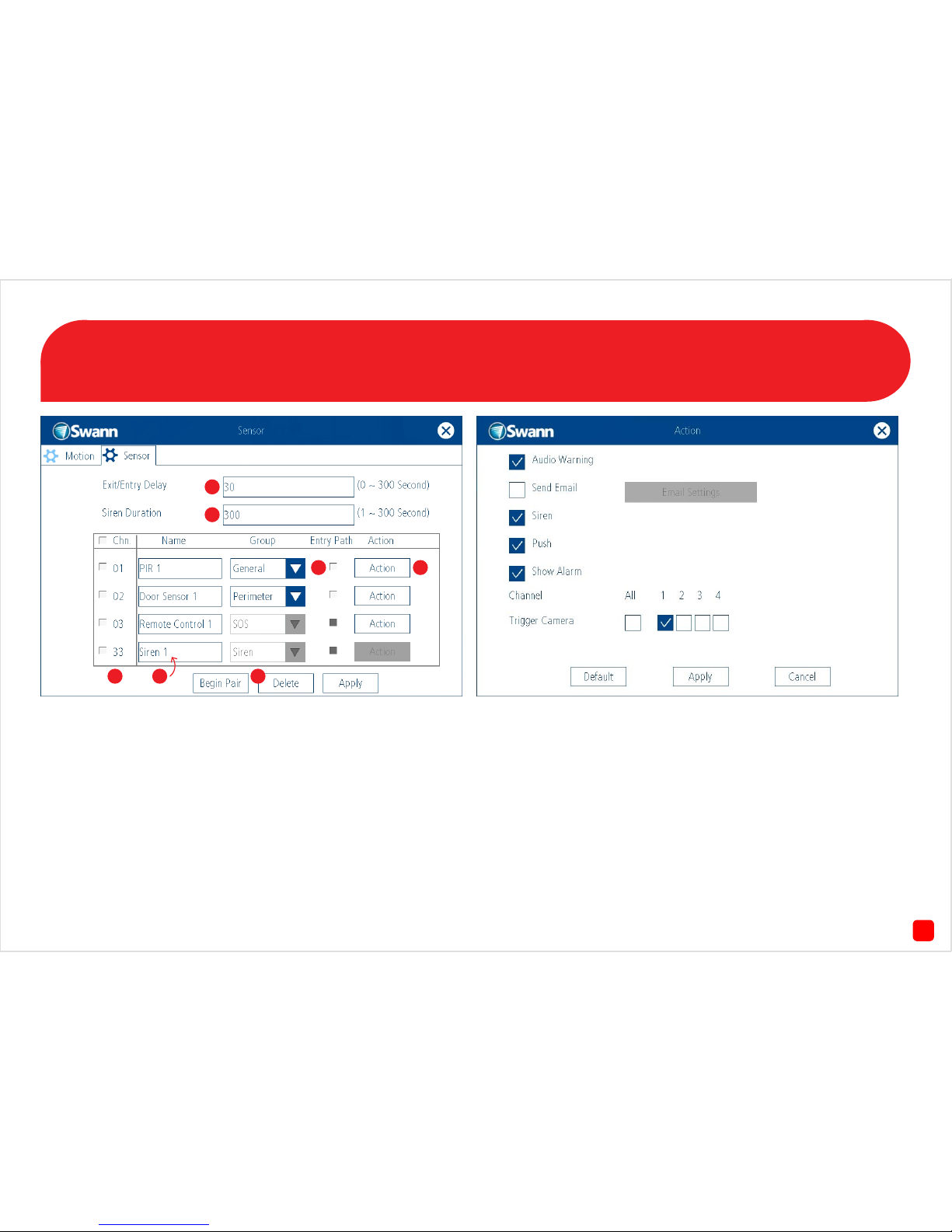
9
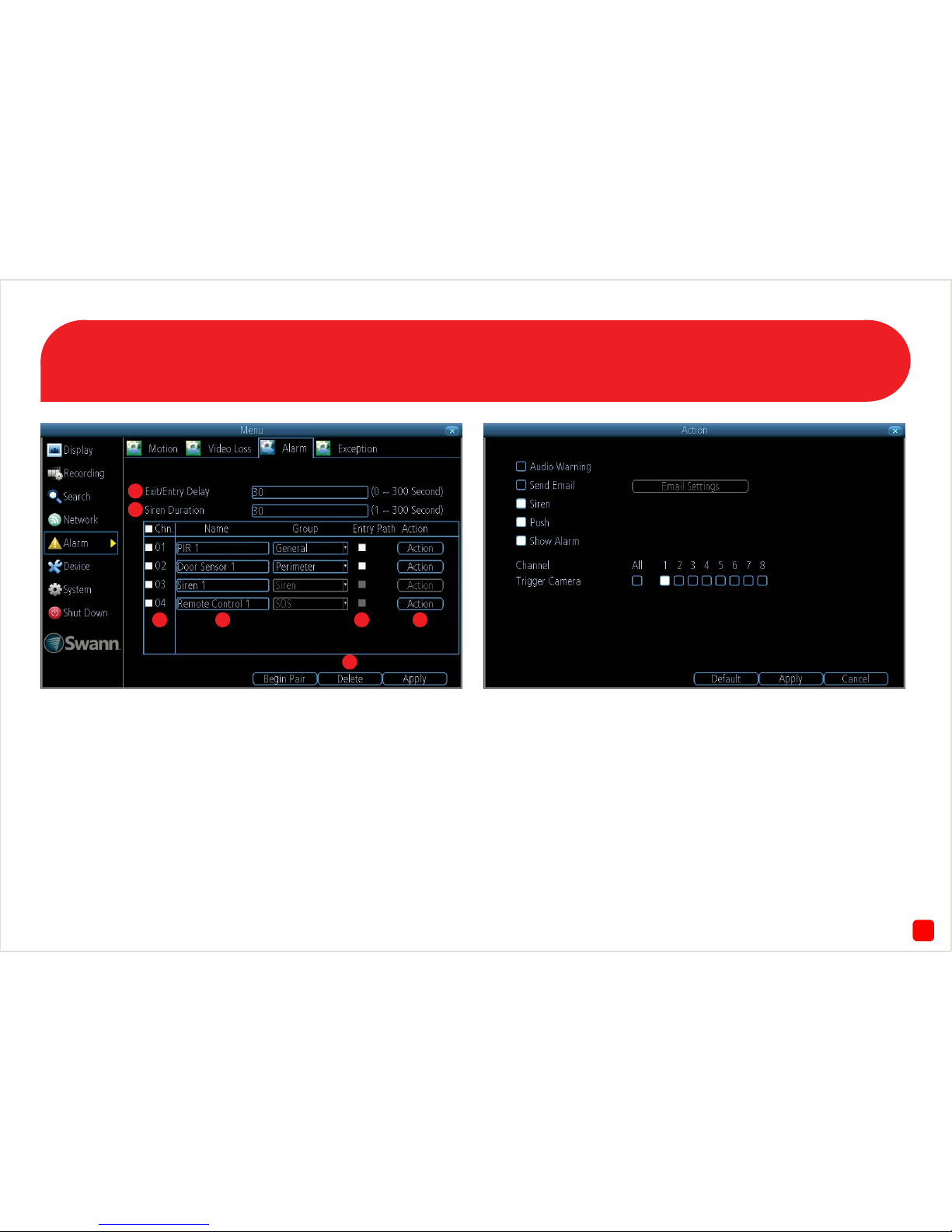
1. This option allows you to change the length of time that you have to
leave or enter the premises before the wireless siren will be activated.
This is linked to the “Entry Path” option.
2. Change this according to how long you want the wireless siren to
sound when activated.
3. Click to select a paired sensor, remote control or wireless siren.
Please note, when a sensor or remote is activated, the channel number
will momentarily flash red.
4. Click to change the name of the paired sensor, remote control or
wireless siren. Up to sixteen characters can be used.
5. Click to delete a paired sensor or remote when selected.
6. Select this if the sensor will be activated when entering or leaving
your home. This gives you extra time (that you’ve selected for exit and
entry) to disable the siren before the sensor is activated.
7. Click to enter the “Action” menu (see above screenshot). When a sen-
sor has been activated, you can instruct the NVR to emit an audio warning, send an email, activate the siren, send a notification to the SwannView Link app and to display a warning on-screen. You can also trigger
the NVR to record from one or more cameras. Click the “Apply” button to
save any changes. Right-click to go back to the previous screen.
Sensor Alarm Configuration
1
2
3 4
7
5
6
Page 10
10
QHW_ALARMCD290914E | © Swann 2014
Alarm Security Kit - DVR EN
The alarm configuration menu (see above screenshot) allows you to
configure and change settings for the PIR movement sensors, window/
door sensors, remote controls (key fobs) and wireless siren.
All movement sensors, window/door sensors, remote controls and
wireless siren are paired with your USB antenna during manufacture.
Pairing instructions are provided in case you have to restore your DVR
to default settings. All sensor and siren devices will have to be re-paired
as per the instructions in this quick start guide.
To access the “Alarm Control” menu, right-click the mouse at the
Live View screen to access the Menu Bar, then click the “Alarm” icon.
The alarm control function allows you to enable all alarms
(Arm), a perimeter alarm
(Home) or to disable the alarm
(Disarm). You can also use the
remote control to enable or
disable the same functions.
1
Page 11
132
Connecting the USB Antenna
AUDIO
OUT
VGA
eSATA
HDMI LAN USB B A
PTZ
DC 12V
IN
VIDEO INAUDIO IN
1 3
2 4
1 3 5 7
2 4 6 8
Connect the mini-USB connection on the
provided USB cable to the mini-USB port
on the USB antenna. Connect the other
end to a spare USB port either at the rear
or the front of the DVR.
When the USB antenna is connected to
the DVR you will see a blue LED at the top
and bottom.
The top and bottom LED will flash blue
to indicate the USB antenna is initialising.
The LED will stop flashing when the
antenna is ready.
The bottom LED will flash red when the
wireless siren has been triggered.
If the DVR hasn’t detected the USB antenna, you will see
“Motion” at the Main Menu instead of “Alarm”. Make sure
the antenna is connected correctly then restart the DVR.
Page 12

163
The PIR Movement Sensor
1. LED - Will flash red to indicate
that movement has been
detected.
2. PIR Sensor - Is an electronic
sensor that can detect warm
moving objects in its field of view.
1234
ON
OFF
1 2 MODE
ON OFF 1-pulse
OFF ON 2-pulse
OFF ON 3-pulse
3 4 MODE
ON OFF TEST
OFF ON NORMAL
OFF ON CODING
1
2
3
4
3. Tamper Button - If the back
cover has been removed, an alert
will be sent to the DVR.
4. DIP Switches - Do not adjust
these as they have been set
correctly during manufacture.
Using a flathead screwdriver, insert this into the clip at the bottom
of the movement sensor to open
the back cover.
Install the provided 3V battery into
the battery compartment. Put the
cover back on when you have
finished and follow the pairing
instructions on page 6.
Insert the mounting bracket at
the top of the movement sensor.
Push down until it clicks into place
as illustrated above.
Page 13

114
The Window/Door Sensor
1. Window/Door Sensor.
2. Using a flathead screwdriver, gen-
tly press down the button at the top
and use a downward motion to open
the cover.
3. The LED will flash green during
normal operation. You will momentarily see a solid green LED
when the sensor has been activated.
4. The width between the magnet
sensor and window/door sensor
should be no more than half an
inch (1.25 cm) apart.
5. Install the provided 3V battery into
the battery compartment. A green
LED will start to flash.
6. The pair/tamper button pairs
the window/door sensor to your
DVR. Follow the pairing instructions on page 7.
7. The wired sensor connects
here. Please note, the wired door
sensor is an optional installation.
1
2
3 4
5
6 7
Thread the wired sensor cable
into the window/door sensor
(see below illustration). Use
a Phillips head screwdriver
to tighten the cable into the
terminal.
The wired sensor can be used
if you have double windows
or doors within the house or
if you have a sliding door that
has a corresponding security
door. Put the cover back on
after pairing.
Page 14

145
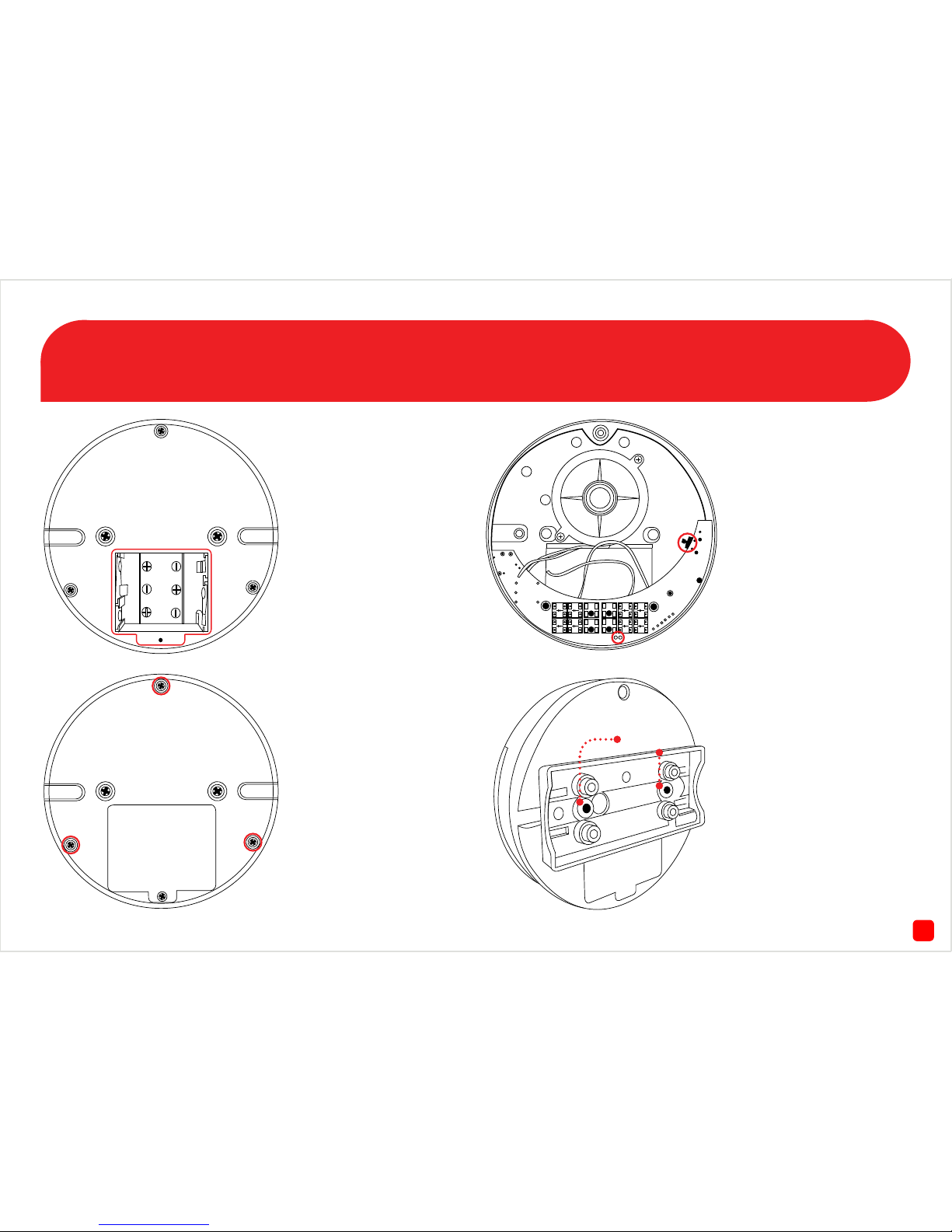
The Wireless Siren
Fig. 1 - Use a Phillips head
screwdriver to remove the
battery cover. Install 3 x AA
batteries provided. Put the
cover back on when you
have finished and fasten the
screw.
Fig. 2 - To access the pair
button, use a Phillips head
screwdriver to remove three
screws as illustrated on the
left. Carefully remove the
cover and try to minimise
any contact with the internal
components.
Fig. 3 - The pair button is
located on the right and the
green and blue LEDs are located at the bottom. Follow
the pairing instructions on
page 8. Put the cover back on
after pairing and fasten all
three screws.
Fig. 4 - Use the mounting
bracket to install the wireless siren to a wall or ceiling.
Please note, there is a tab on
the back of the siren which
locks in with the groove on
the mounting bracket. Slide
the siren to the right to lock
it in place.
Bracket Mount
Page 15
176
Pairing the PIR Movement Sensors
1. To access the “Alarm” menu, right-click the mouse at the Live View
screen, click “Menu”, click “Alarm” then click the “Alarm” tab.
2. Click “Begin Pair”.
3. Activate the movement sensor by moving in front of it. The LED will
flash red and the DVR will detect the sensor and add it to the sensor list.
Repeat this step for any other movement sensors.
Please note, to conserve battery power, the PIR movement sensor when
activated will wait five seconds to activate again.
Group - There are three options available to group your sensors. For
the PIR movement sensor it is recommended that you set this to “General”. This means any movement within the vicinity of the sensor will
then activate the wireless siren to be activated when you select “Arm”
in the “Alarm Control” menu. You can change this group when you have
finished pairing.
Page 16

127
Pairing the Window/Door Sensors
1. If the window/door sensor has the cover on, follow the instructions on
page 4 to gain access to the pair/tamper button.
2. Press and hold the pair/tamper button. You will momentarily see a
solid green LED.
3. The DVR will detect the sensor and add it to the sensor list. Repeat
this step for any other window/door sensors. Put the cover back on when
you have finished.
It’s a good idea to make sure the window/door sensor and the magnetic
sensor are held together to prevent it from triggering.
Group - Leave this as “Perimeter”. The perimeter group allows move-
ment inside the house (when you select “Home” in the “Alarm Control”
menu) but if a window or door is opened this will activate the siren.
Page 17

158
Pairing the Wireless Siren/Remote Control
1. Press and hold the pair button on the wireless siren (see page 5 - Fig.
3). After a short moment you will see a solid blue LED. The DVR will
detect the siren and add it to the sensor list. Put the cover back on after
pairing and fasten all three screws.
2. The battery for the remote control is pre-installed so there is no need
to open the battery cover located at the rear.
3. Press one of the buttons on the remote control. The DVR will detect
the remote control and add it to the sensor list. Repeat this step if you
have more than one remote control.
4. Click “End Pair” then click “Apply”.
Group - The remote control is always set to “SOS” and cannot be
changed.
Don’t forget to click “Apply” otherwise any changes made will not be
saved.
1) Transmit LED - If you don’t see a red LED
when you press a button, this indicates the
battery is flat.
2) Panic - Click this to activate the wireless
siren instantly.
3) Alarm On - Click this to enable all sensors
listed in the sensor list.
4) Alarm Off - Click this to disable all sensors
listed in the sensor list.
5) Perimeter On - Click this to enable all win-
dow/door sensors only. This allows movement
inside the house but if a window or door is
opened this will activate the wireless siren.
2
3
4
5
1
Page 18
18
Sensor Alarm Configuration
9
1. This option allows you to change the length of time that you have to
leave or enter the premises before the wireless siren will be activated.
This is linked to the “Entry Path” option.
2. Change this according to how long you want the wireless siren to
sound when activated.
3. Click to select a paired sensor, remote control or wireless siren.
Please note, when a sensor or remote is activated, the channel number
will momentarily flash red.
4. Click to change the name of the paired sensor, remote control or
wireless siren. Up to sixteen characters can be used.
5. Click to delete a paired sensor or remote when selected.
6. Select this if the sensor will be activated when entering or leaving
your home. This gives you extra time (that you’ve selected for exit and
entry) to disable the siren before the sensor is activated.
7. Click to enter the “Action” menu (see above screenshot). When a sen-
sor has been activated, you can instruct the DVR to emit an audio warning, send an email, activate the siren, send a notification to the SwannView Link app and to display a warning on-screen. You can also trigger
the DVR to record from one or more cameras. Click the “Apply” button to
save any changes. Right-click to go back to the previous screen.
1
2
3 4 6 7
5
 Loading...