

1
NVR Quick Start Guide
• Getting to know your NVR
• What does this mean?
• Installing the Wi-Fi Antennas
• Connect your Cameras
• Connect your NVR to your Home Network
• Connect your Mouse
• Connect your NVR to your HDTV
• Connect your Power Adapter
QHGUAEYE111215E | © Swann 2015
Welcome! Lets get started.
READ ME
FIRST!
2
Congratulations on the purchase of your Swann NVR. This quick start guide will assist you on getting your NVR up and
running as soon as possible. We recommend that you connect everything and give it a try before you do a permanent
installation, to make sure nothing was damaged during shipping. On the other side is a detailed connection map which
illustrates the various connections on the NVR.
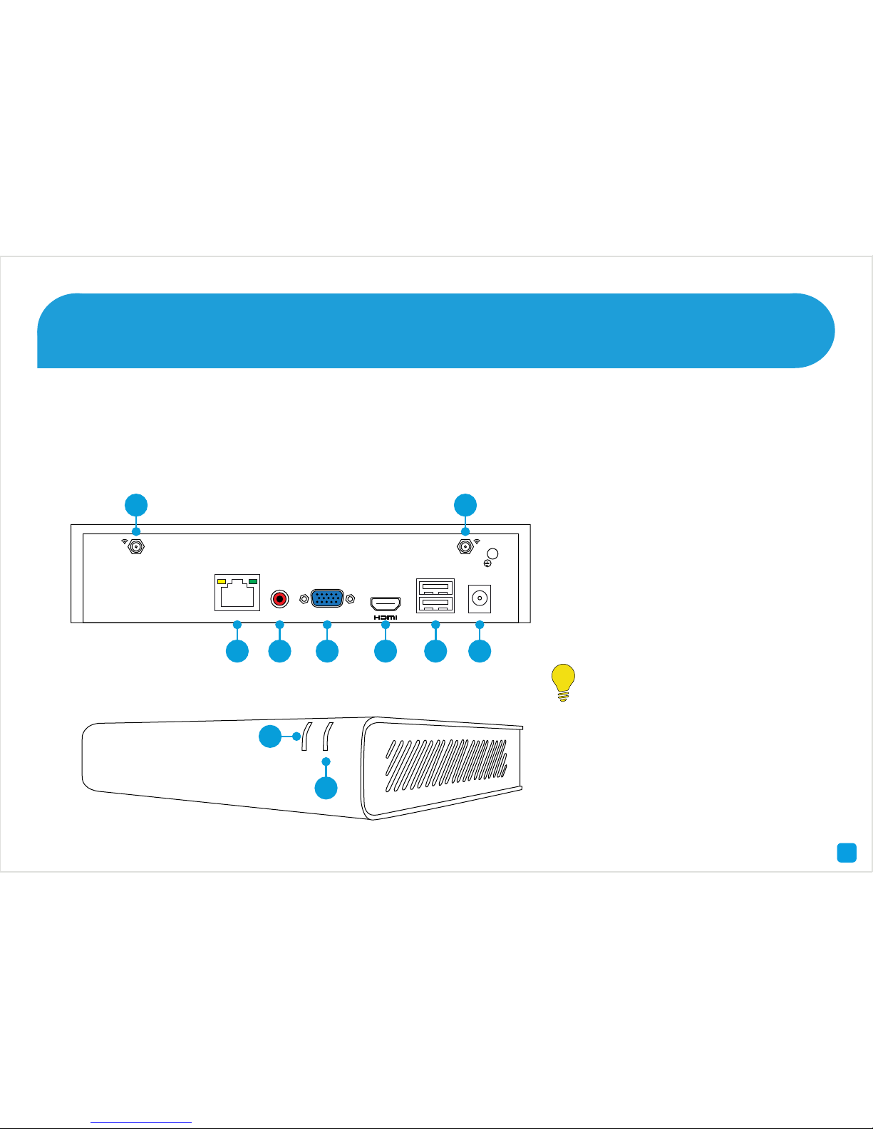
Getting to know your NVR
1) Wi-Fi Input
2) LAN
3) Audio Out
4) VGA
5) HDMI
6) USB
7) Wi-Fi Input
8) Power Input
9) PWR LED
10) HDD LED
Look out for the light bulb icon,
as this provides information on
the operation of your NVR.
PWR HDD
4 Channel HD Network Video Recorder
10
VGA
USB
AUDIO
OUT
LAN
DC 12V IN
1
2 3 4 5 6 8
7
9

3
1 & 7) Wi-Fi Input - The supplied Wi-Fi antenna connects
here. The Wi-Fi antenna communicates with the supplied
cameras as well as your Wi-Fi network.
2) LAN - Connect this to your home network so your NVR
can connect to the Internet (required for AP mode only).
3) Audio Out - For connecting speakers.
4) VGA - If you have a digital TV or a monitor with a
VGA connection, connect this to an available input (this
connection is not required when using the HDMI cable).
5) HDMI - Connect this to your digital TV with a HDMI input
(HDMI cable supplied).
6) USB - Connect the mouse here. Also able to connect
a storage device such as a USB flash drive to back up
recorded events or to perform a firmware upgrade.
8) Power Input - Connect the DC 12V power adapter here.
9) PWR LED - Indicates the NVR has power.
10) HDD LED - Will flash when the hard drive is working.
What does this mean?
FCC Note: This equipment has been tested and found to comply with the
limits for a Class B digital device, pursuant to part 15 of the FCC Rules.
These limits are designed to provide reasonable protection against
harmful interference in a residential installation. This equipment
generates, uses and can radiate radio frequency energy and, if not
installed and used in accordance with the instructions, may cause
harmful interference to radio communications. However, there is no
guarantee that interference will not occur in a particular installation. If
this equipment does cause harmful interference to radio or television
reception, which can be determined by turning the equipment off and
on, the user is encouraged to try to correct the interference by one or
more of the following measures -
• Reorient or relocate the receiving antenna
• Increase the separation between the equipment and receiver
• Connect the equipment into an outlet on a circuit different from that
to which the receiver is connected
• Consult the dealer or an experienced radio/TV technician for help
Caution: Any changes or modifications to this device not explicitly
approved by manufacturer could void your authority to operate this
equipment. This device complies with part 15 of the FCC Rules. Operation
is subject to the following two conditions: (1) This device may not cause
harmful interference, and (2) this device must accept any interference
received, including interference that may cause undesired operation.

4
Step One - Installing the Wi-Fi Antennas
1. Located at the rear of your NVR are two Wi-Fi antenna
connections. There is also a single Wi-Fi connection at the
rear of each camera.
2. As there are several Wi-Fi antennas provided, use the
two longer versions for your NVR and the shorter versions
for each camera.
3. Use a clockwise motion to connect. Make sure the
antenna is connected firmly but not excessively. It is
recommended to leave the antenna in a vertical position
for best reception.
HD M I
US B
DC 12V
IN

5
1. Connect the Power Input on the camera to the Power
Output on the Power Extension Cable. Repeat this step for
each camera provided.
2. Connect the Power Input on the Power Extension Cable
to the Power Adapter. Repeat this step for each Power
Adapter provided.
3. Connect each Power Adapter to a wall socket. Press the
wall socket’s switch to the on position to supply power.
Reset - To reset your camera, press and hold the reset
button, connect power and continue holding for 10 seconds.
LAN - This can be used to configure your camera to your
Wi-Fi network.
Step Two - Connect your Cameras
21
LAN
Reset
Power
Input
Power
Output
Power
Input
Power Extension
Cable
Power Adapter
3

6
Connect the supplied Ethernet cable (1) to the LAN connection on the NVR then connect the other end to a spare port
on your router or wireless access point. Don’t proceed to the next step until this is done.
Please note - AP mode allows wireless communication with your cameras, however your NVR must be
connected to your router to send email alerts, synchronise its internal clock and for remote access.
Step Three - Connect your NVR to your Home Network
1
USB
Internet
4
3
2
VGA
USB
AUDIO
OUT
LAN
DC 12V IN

7
Connect the supplied mouse (1) to one of the available USB ports. You can connect a USB storage device such as a
flash drive (not included) to the other port, to back up your video recordings and to perform a firmware upgrade.
Step Four - Connect your Mouse
Please note - Bluetooth and wireless mice and trackpad devices are not supported. Not all USB storage devices
are supported.
1
VGA
USB
AUDIO
OUT
LAN
DC 12V IN

8
Connect the supplied HDMI cable to the HDMI output on the NVR then connect the other end to a spare HDMI input (1)
on your HDTV. Make sure the video input on the HDTV matches the physical connection used to connect the NVR.
Step Five - Connect your NVR to your HDTV
HDMI IN 2
HDMI IN 1
1
VGA
USB
AUDIO
OUT
LAN
DC 12V IN

9
Connect the supplied power adapter’s power connection (1) to the power input on your NVR first (this will minimise
sparking) then connect the power adapter to a spare wall socket (illustration may differ from what is supplied).
All the connections have now been completed. You’re now ready to run through “The Wizard” quick start guide (the red
coloured one) to configure your NVR.
Step Six - Connect your Power Adapter
1
VGA
USB
AUDIO
OUT
LAN
DC 12V IN
 Loading...