

Page 1
1
SW331-PR6
www.swannsecurity.com
SR331-PR6-60010-040909
Operating Instructions
PRO-650™
™
™
Advanced security made easy
Pan Tilt Zoom
Dome Camera
Page 2

222
FCC Verification:
NOTE: This equipment has been tested and found to comply with the limits for
Class B digital device, pursuant to part 15 of the FCC Rules. These limits are designed to provide reasonable protection against harmful interference in a residential installation. This equipment generates, uses and can radiate radio frequency
energy and, if not installed and used in accordance with the instructions, may
cause harmful interference to radio or television reception, which can be determined by turning the equipment off and on, the user is encouraged to try to correct the interference by one or more of the following measures:
· Reorient or relocate the receiving antenna
· Increase the separation between the equipment and the receiver
· Connect the equipment into an outlet on a circuit different from that to which
the receiver is connected
· Consult the dealer or an experienced radio/TV technician for help
IMPORTANT NOTE: Prohibition against eavesdropping
Except for the operations of law enforcement officers conducted under lawful
authority, no person shall use, either directly or indirectly, a device operated pursuant to the provisions of this Part for the purpose of overhearing or recording the
private conversations of others unless such use is authorized by all of the parties
engaging in the conversation.
WARNING: Modifications not approved by the party responsible for compliance
could void user’s authority to operate the equipment.
IMPORTANT SAFETY INSTRUCTIONS:
· Make sure product is fixed correctly and stable if fastened in place
· Do not operate if wires and terminals are exposed
2
Before You Begin
FOR BEST RESULTS:
This is a semi-professional 360º PTZ dome camera, conforming to PELCO P/D standards. To obtain the best image quality, please use a high quality cable, particularly if
the cables required length exceeds 100ft/35m. For the highest video quality, use a
cable with a solid copper inner conductor and shielded with copper braid.
Page 3

3
Contents
Before you Begin 2
Table of Contents 3
Quick Reference 3
Overview 4
Package Contents 4
Layout of the Camera and PTZ Controller 5
Layout of Remote Control 6
Connecting the Camera 8
Mounting the Camera 10
Setting the Command Address 12
Configuring the PTZ Controller 12
Connecting Multiple PTZ Systems 13
Operating the Camera 14
Advanced Operation 16
Additional Functions 17
Troubleshooting Guide 18
Technical Specifications 19
Warranty / Technical Support Rear Cover
Quick Reference
PRO-650 4” Pan, Tilt, Zoom Dome
Default PTZ Configuration
Default Command Address: 1
Protocol: Pelco-D
Baud Rate: 2400bps
RS485 Polarity:
+A Purple Wire
- B White Wire
Page 4
444
Overview
Congratulations on your purchase of this 360º PTZ Camera Dome! This system
is an ideal solution for monitoring a large area – a combination of a quality Sony
CCD image sensor mounted in a contained dome with the option to pan fully
360º. Nothing will be out of sight for long!
Whether you wish to do this using the full complement of manual controls, or
program a detailed surveillance program for the camera to run, the PRO-650 gives
you all the options you need to simply and effectively monitor a large range of
locations without the hassle of multiple cameras.
The PRO-650 features an included fully functional PTZ controller, great low-light
performance and a 3x optical zoom – great for getting up close to what you want
to see. All this comes mounted in a simple but elegant 4” dome.
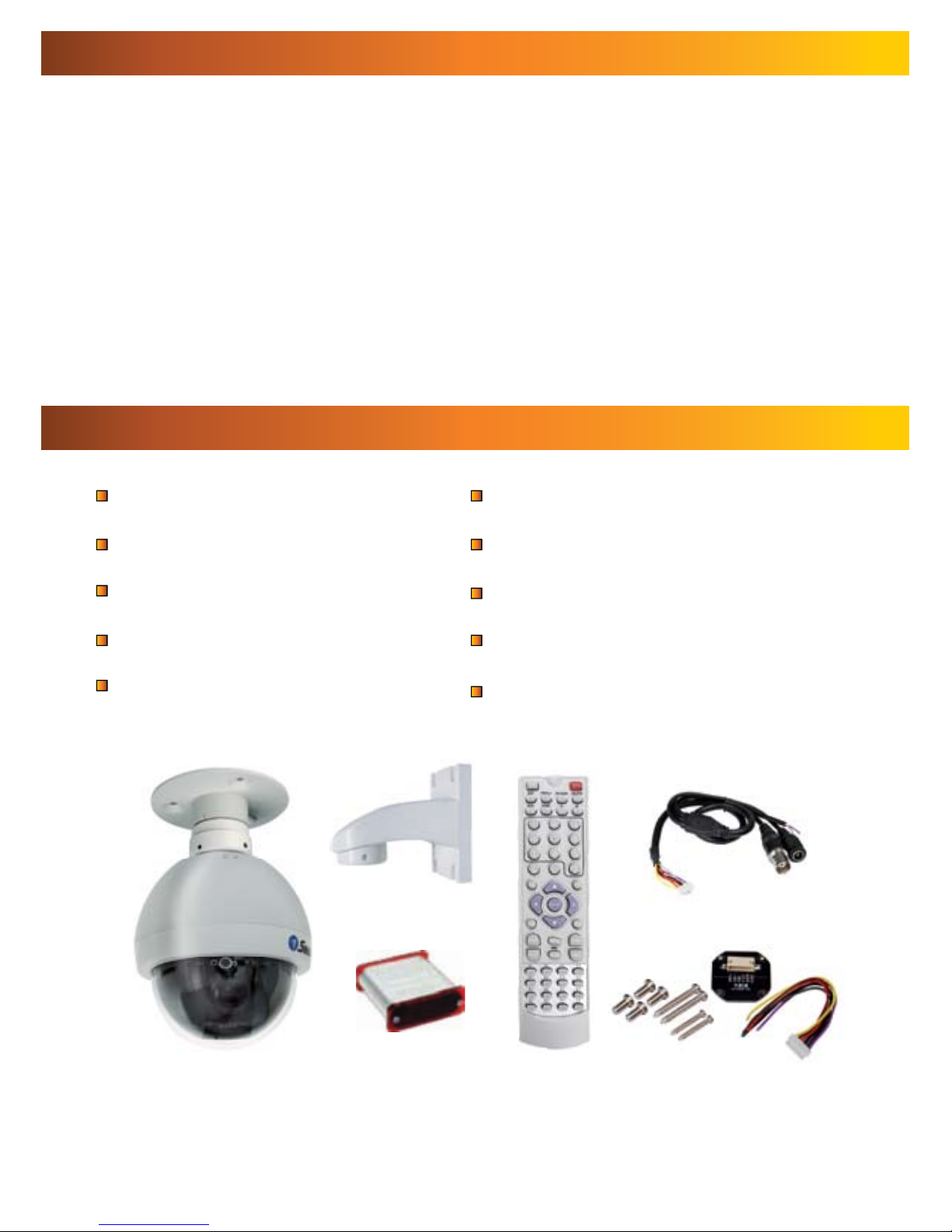
PRO-650 PTZ 4” Dome Camera
Roof Mounting Arm/Bracket
Wall Mount Arm
PTZ Controller/Receiver
Remote Control
Mounting Screws
Operating Instructions
2 x Power Adaptors (DC 12V)
50ft (15m) RS485 Command Cable
Spare Camera Cable & Plug Board
Package Contents
If any of these components are missing, contact Swann Technical Support.
Contact details are on the back cover of this booklet.
Page 5
55
Layout of the Camera and PTZ Controller
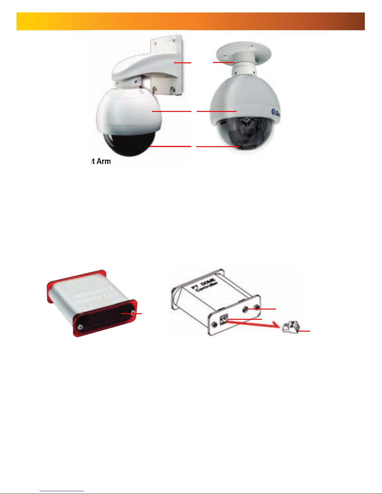
1. Wall-Mount Arm
For mounting the PRO-650 Dome to a wall, post or similar vertical surface.
2. Ceiling-mount Bracket
For mounting the PRO-650 Dome to the underside of a ceiling or overhang.
3. Camera Housing
Contains the camera, PTZ unit and associated circuitry and electronic components.
4. Dome Cover
Protects the camera.
4
132
5. LED Display
Displays the current status of the PTZ controller.
6. DC 12V
Connect the supplied power adaptor to this socket.
7. RS485 Port
Insert the RS485 plug into this socket.
8. RS485 Plug
Connect the end of the purple and white control wires into this plug, using the attached screws
to secure wires in position. The PURPLE wire is “+”, the WHITE wire is “-”.
8
6
7
Rear View
Front View
5
Page 6
666
Layout of Remote Control
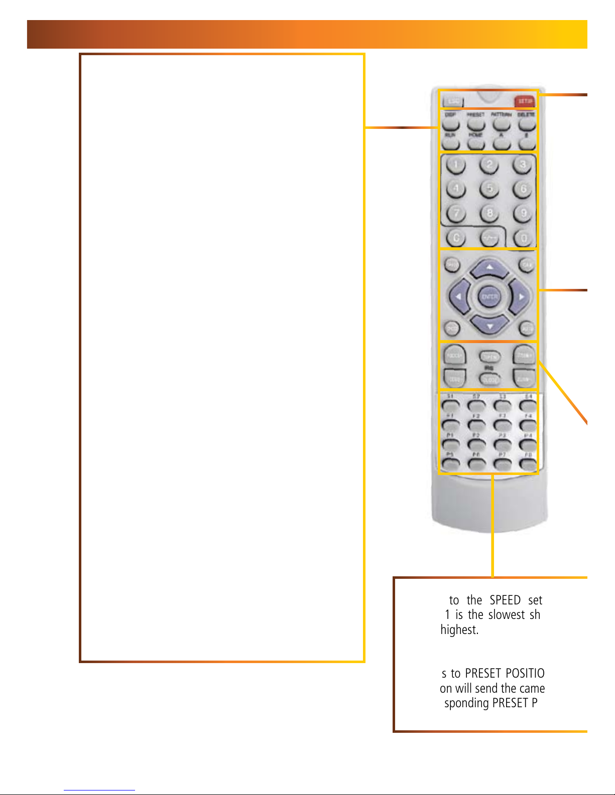
DISP (Display)
Toggles the display on the front of the PTZ Controller,
showing the Command Address, Protocol and Baud
Rate.
PRESET (HOLD to define)
Changes or accesses preset points.
PATTERN (press and HOLD)
Allows for the programming of lists of preset points for
the camera to view in sequence.
DELETE (press and HOLD)
Will remove a Preset Point or Pattern.
RUN
Commands the system to begin executing the
programmed pattern.
HOME
Master Preset Point. Whilst not in Cruise Mode
(see page 15) the camera will automatically
return to this position whilst idle.
A & B
Master Preset Points. They are defined in the same way
as other Preset Points (see page 14). They operate as
shortcut buttons thereafter.
0 – 9
The number buttons. Used to enter a numerical value
into the PTZ controller.
C
Clear. Removes the last digit entered into the controller,
somewhat like the ‘backspace’ key on your computer.
-/--
Allows for the entry of more than one digit at a time. “-”
represents a single digit, whilst “--” indicates space to
enter two digits.
S1 ~ S4
Shortcut to the SPEED setting for the
camera. 1 is the slowest shortcut speed,
4 is the highest.
P1 ~ P8
Shortcuts to PRESET POSITIONS. Pressing
the button will send the camera directly to
the corresponding PRESET POSITION.
5
Page 7
7
ZOOM + / -: Increases and decreases the level of magnification, respectively.
The PRO-650 features a 3x optical zoom.
FOCUS + / - and
IRIS OPEN / CLOSE
The PRO-650 PTZ Dome features automatic focus and exposure adjustment.
As a result, you will not need to use these buttons whilst operating the PRO-
650. They’ve been included on the remote so that the controller can be used
for multiple PTZ systems (including ones without automatic focus and exposure
adjustment) if you choose.
ARROWS
Used to move the camera.
SHOT
Readies the controller to accept a numerical
value for a Preset Position, noted on the display
by the letter “P”.
CAM
Readies the controller to accept a new
Command Address (use numerical buttons to
enter a new value).
ENTER
Confirms a selection. Whilst the camera is
moving, ENTER will hold it still.
SPEED
Adjusts the speed at which the camera moves.
Higher numbers represent faster speeds.
AUTO
Toggles Auto-scan Mode on and off. Whilst in
Auto-scan Mode, the camera will continually
move as it attempts to sweep the entire field
of view as efficiently as it can.
FOR MORE detailed information about operating
the PTZ features of the PRO-650 Dome, see
Operating the Camera on page 14.
ESC (Escape)
Stops the current action and returns to the
default interface. Aborts half completed
sequences, such as programming a cruise
pattern.
SETUP
Readies the PTZ Controller to accept new
values for Baud Rate and Protocol. The “p”
and “d” are protocols (Pelco-P and Pelco-D
respectively) and the numerical value is the
abbreviated Baud Rate.
Page 8
888
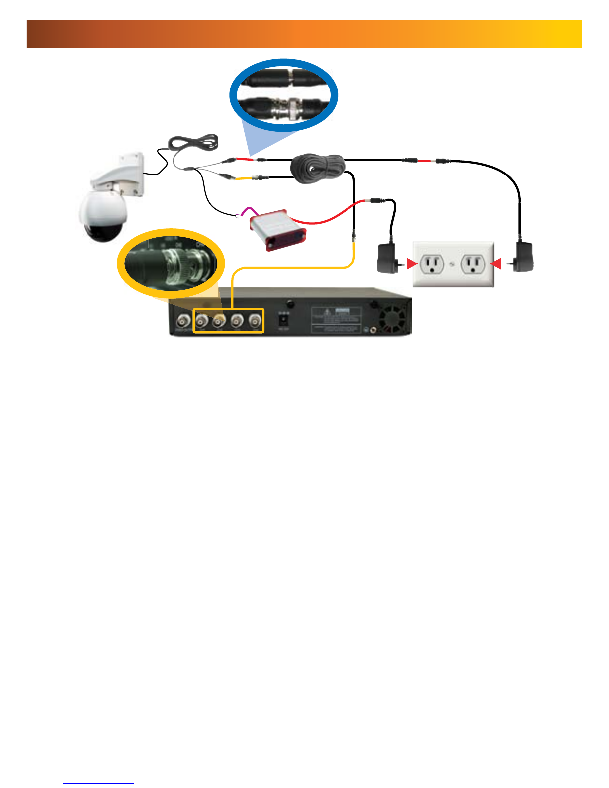
Connecting the Camera
1
2
5
7
4
3
After running the camera cable through the mounting arm/bracket, 1.
attach to the main plug on the camera circuit board (see opposite).
Connect the BNC connector and power connectors to an extension 2.
cable.
Connect the purple and white wires to the RS485 plug, and insert 3.
the RS485 plug into the RS485 port on the rear of the controller (see
opposite).
Attach the BNC plug on the end of the extension cable to a BNC input 4.
on your TV, VCR or DVR (as applicable). If your monitor/recorder does
not have a BNC connection, then use a BNC to RCA adaptor.
Connect the power connector on the end of the extension cable to 5.
the DC plug of a power adaptor (DC 12V).
Attach the power connector on the rear of the PTZ controller to a 6.
power supply (DC 12V).
Plug the DC 12V power adaptors into mains power.7.
6
Page 9

9
1. Connecting the Camera Cable
Before mounting the camera, it is
important to connect it correctly.
Run the cable through the mounting 1.
arm or bracket you would like to
use.
Make sure you run the cable 2.
through starting with the camera
end (not the end with the BNC
connectors - they’re too big to fit).
Once the cable has been pulled 3.
through, plug it into the top of the
camera.
If you’re planning to mount the 4.
dome outside, cover the screw
threads with a silicon sealant before
screwing the unit together. Failing
to do so will compromise the
waterproofing of the dome.
Then, screw the mounting arm/5.
bracket onto the dome.
Be careful not to damage the connectors
on the end of the cable or to the camera,
particularly when unplugging the
camera, as the connectors are fragile!
3. Connecting the RS485 Cables
Remove the RS485 plug from the back of 1.
the PTZ controller.
Insert the WHITE wire into the -B side of 2.
the RS485 plug, and screw into place.
Insert the PURPLE wire into the +A side of 3.
the RS485 plug, and screw into place.
Plug the RS485 plug into the RS485 port 4.
on the back of the PTZ controller.
Note: If you need a longer cable to reach
the location you’d like to put the PTZ
controller, the RS485 cable can be extended.
If you are unfamiliar with cable construction
and maintenance, we suggest getting a
professional to do this.
Page 10
101010
NOTE: Before you begin, be sure that there are no live electrical cables in the area
you wish to mount the camera.
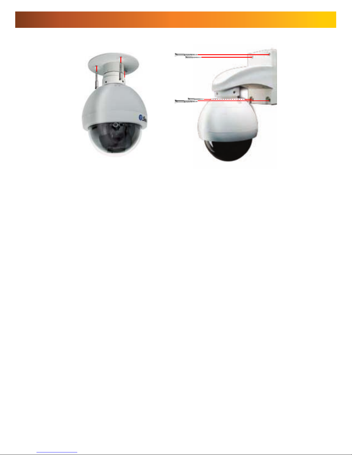
To mount the camera:
After connecting the camera as described on page 8 and installing the cables as
shown on page 9, place it in the desired location. Then, using an appropriate screw
for the surface you’re fixing the dome to, screw the arm/bracket into place.
Ensure you have enough cable coming through the mounting arm/bracket to
connect it to your system. If you want to run the cables through a wall/ceiling, be
sure to drill a hole for the cable as well.
Placement Tips
For best results, carefully consider where you want to mount the dome. Whilst the
optimal placement solution will vary form application to application depending
on intent of installation, the environment of use and the lighting conditions
encountered there, there are a few points which are almost universal.
What you want to monitor:
The most obvious factor to consider when planning where to install your camera is
the question of what you wish to monitor, and how a movable PTZ system can be
incorporated into your specific environment.
Ensure that the camera is located close enough to what you want to monitor •
to capture the required details. For example, if you wish to capture the details
of a face, the camera should be located within a dozen feet (about 4m) of
the subject. This is also true if trying to read printed information - such as a
vehicle’s registration plate.
Try to place the camera in an position that a potential security threat will find •
it difficult to avoid.
A strategy which is often effective is to monitor entrances and exits - after all, •
a security threat has to get in somewhere.
Mounting the Camera
Page 11

11
Field of view
The PRO-650 can pan a full 360º. This means that (for example) installing the
PRO-650 in a tight corner is probably not an ideal utilization of its potential! A wall
is a better option, as it allows 180º of view for the camera. A freestanding pole
of sufficient height and integrity to reliably hold the camera securely is an ideal
choice, as is the centre of the ceiling in a larger room or a warehouse.
Height
For best results, the PRO-650 PTZ Dome should be mounted as high up as
practicable. This is because the camera has complete freedom of tilt movement
in the 90º below the horizontal plane. Stated more simply, it can see things below
it, but not above! Extensions for the provided mounting hardware are available
through our online store.
Joining Cables
We strongly advise against the modification (i.e. cutting and/or joining) of video
cables. Each cut/join will noticeably reduce video quality, and increase the chances
of the system failing over time. We also advise against using cable joiners/adaptors
to plug multiple cables together. Rather, we suggest using a single unmodified
video cable, chosen in accordance with the guidelines below.
Recommended Cable Length and Type
Being a semi-professional PTZ dome system, the PRO-650 benefits greatly from
being installed using high quality cables to minimise video signal loss. This becomes
particularly important if using a cable longer than approximately 100ft/35m. The
longer the cable used to carry the video signal, the more noticeable the reduction
in video quality will become.
To maximise the quality of the video signal, consider using a high quality video
cable or installing your monitor/recording device closer to the PTZ dome. Of course,
in many circumstances, moving the monitor/recording device is not a viable option;
in these cases, a high quality cable is the best solution.
For optimal results, use a single, unbroken coaxial cable with a solid
copper core and copper braid shielding.
Exposure to Weather
The Pro-650 PTZ Dome is weather and water resistant (rated IP66). However, be
aware that long term exposure to adverse weather conditions (extreme temperature
uctuation, excessive moisture or direct sunlight) may eventually interfere with the
correct operation of the unit.
IMPORTANT: If mounting the camera outside, be sure to properly seal all
joints in the mounting arm/bracket using a silicon sealant. If this is not
fully sealed, water can enter the dome causing malfunction or failure.
Page 12

121212
Configuring the PTZ Controller
Setting the Command Address
The included PTZ controller is capable of controlling multiple PTZ cameras. Thus,
each camera needs its own unique identification (a “Command Address”).
To define a camera’s Command Address, connect the camera (and only that
camera) to the PTZ controller. Then:
Press the CAM key. The display will now show Axxx (where “xxx” is the current •
Command Address assigned to the controller).
Enter the Command Address that you’d like to assign to the camera. For •
numbers higher than 10, press the -/-- key first.
Press and hold the PRESET button. The display will change to SET-•
To confirm changes to the Command Address setting, press the SETUP button. •
The display will show –OH–.
The camera’s Command Address has now been changed to your desired •
value.
Please note that if you press the CAM button then enter a number, you are changing
the Command Address in the PTZ controller, but not in any cameras. Holding
PRESET then pressing SETUP applies that address to the connected cameras.
When we define a command address, that address is applied to all cameras
connected to the controller at once. Thus, if you have two cameras connected
to the PTZ controller at once, enter a command address of “005” into the PTZ
controller and press PRESET then SETUP, both cameras will now respond to the
controller on Command Address 005, and cannot be operated individually until
one camera’s Command Address is changed so that both are unique.
Default Settings:
Protocol = Pelco-D
Baud Rate = 2400bps
To ensure that the Controller knows how to
command the PRO-650, we need to make sure
it is using the correct Protocol and Baud Rate. If
these are not set correctly, the PRO-650 will not
operate properly (or at all).
To change the Protocol and Baud Rate:
Press and hold the SETUP button.•
The display on the Controller will change to a letter (either “d” or “p”) and a •
number (12, 24, 48 or 96).
The letter represents the current protocol, either Pelco-P or Pelco-D.•
The number is the abbreviated Baud Rate. •
(i.e. “12” represents 1200bps, “24” represents 2400bps and so on)
Use the UP and DOWN arrows to change the Protocol.•
Use LEFT and RIGHT to change the Baud Rate.•
When set correctly, the letter should be “d” and the number “24”•
Press ENTER to save your changes.•
Page 13

13
Connecting Multiple PTZ Systems
Connecting multiple PTZ systems to the included controller is a convenient way to
be able to access and control a complex, multi-camera system from one central
location. This is, however, and advanced feature of PTZ systems, and should
only be attempted by those experienced with security system and/or networking
technologies. In a nutshell: multiple systems can be connected to the RS485 cable
in a bus or line configuration. The exact details of the wiring solution will vary by
environment - the following is presented only as a guide.
Please Note: If you already have, or are planning on getting, a PTZ capable Swann
DVR, then using the supplied PTZ controller is optional. The PTZ system can be
controlled by the RS485 connection built into the DVR.
In the above example, three PTZ domes have been connected to the one central
controller. To achieve this wiring arrangement:
Connect the PTZ systems one at a time, and follow the instructions opposite •
to assign each camera a separate command address.
Multiple cameras sharing a command address can cause problems when •
implementing a system. In the best case scenario, two or more PTZ systems
sharing a command address will move synchronously, without the option to
move each camera separately. Often, a shared command address will prevent
the system from operating normally.
Once each camera has a command address defined, they can be connected •
simultaneously.
Take the purple (+) wires, and connect all three to the +A side of the RS485 plug.•
Repeat for white (-) wires, and connect all three to the -B side of the RS 485 plug.•
Connect the RS485 plug to the PTZ controller.•
Diagram showing a potential wiring
solution for integrating multiple PTZ
systems to the one controller.
Page 14

141414
Operating the Camera
Moving the Camera
The easiest way to move the camera is to use the directional buttons. In the
standard live control mode, the camera will move in the direction of the button
which you press.
To make the camera pan left or right, press and hold the LEFT or RIGHT •
directional button, respectively. You can hold down either button continuously,
the camera will continue to pan left or right (around a circle) indefinitely.
To tilt the camera up and down, use the up and down buttons. Note that whilst •
the camera can pan infinitely, the tilt has only a 90º freedom of movement. It
can see everything that happens below the dome, but not above it.
To make objects in the view appear bigger or smaller use the ZOOM controls.•
Setting a Preset Point
Setting Preset Points allows you to program movements for your camera system
to repeat over time, or to remember a specific viewpoint for easy access later. The
PRO-650 can store up to 16 user-defined Preset Positions.
Using the directional arrow buttons, move the camera into the position that •
you’d like it to store as a Preset Position.
Press the PRESET button on the remote, and hold for two seconds.•
The display will now read “SET-”•
Press a number key to assign a Preset number to the position. To define a •
Preset Position with a value higher than 10, press the -/-- button first.
The information in this section assumes that you have the PRO-650 attached
to the supplied IR receiver/PTZ Controller module and have followed the
instructions on page 10 for configuring the Command Address, Protocol
and Baud Rate settings.
Alternately, if you have the RS485 connections to the PRO-650 attached to a
PTZ capable DVR, then use the PTZ controls through your DVR (consult your DVR
manual for more details).
Accessing a Preset Point
The easiest way to access the preset points, use the shortcut buttons, marked P1
through P8. Of course, this only works for the first eight Presets. To access Preset
9 and above:
Press the SHOT button.•
If you’re accessing a point above 10, press the -/-- button.•
Enter the number of the Preset you’d like to access.•
Press ENTER to confirm.•
Page 15

15
Removing a Preset Point
Removing Preset Points is performed in much the same manner as defining them.
Once a Preset Point has been removed, selecting it as detailed opposite will no
longer have any effect, until a new point is set.
Press the DELETE button on the remote, and hold for two seconds.•
The display will now read “Clr-”•
Press a number key to select a Preset Point number. To choose a Preset Point •
with a value higher than 10, press the -/-- button first.
Press ENTER to confirm.•
The selected Preset Point will now no longer be set.•
Cruise Mode
Whilst the PRO-650 is in Cruise Mode, the camera will move continuously and
automatically, only pausing when it arrives at Preset Points for a short interval.
There are two ways to enter Cruise mode.
Auto-scan (Cruise) Mode
When in Auto-scan Mode, the PRO-650 will continuously move automatically,
attempting to observe as much of the field of view as practicable in the shortest
time it can.
To enter Auto-scan Mode, press AUTO.•
For an alternate Auto-scan mode, go to Preset Point 99.•
Manual Cruise Mode
You can program lists of Preset Points for the PRO-650 to view in order.
First, create all the Preset Points you wish to see, as detailed on page 8.•
Press and hold PATTERN for two seconds. •
The display will now read “PStA”.•
Press the NUMBER button for the first Preset Point you want in the programmed •
loop, using the -/-- button to access points higher than 10 if necessary.
Press ENTER once the camera has moved to that Preset Point to confirm.•
Repeat for the other Preset Points you want on the loop, in the order that you •
want them to be accessed. Remember to press ENTER each time to confirm
your selection.
Press and hold PATTERN for two seconds. The display will now show “PSt0” •
confirming that the pattern programming has ended and the pattern has been
saved.
Press RUN to initiate the programmed pattern, and press RUN again to stop •
the pattern.
To reset the Cruise Mode settings to their default values, press PRESET followed •
by -/--, and enter “240”.
Page 16

161616
Advanced Operation
The numerical command functions shown in this section are recommended
only for advanced users. Improper use of these commands may interfere
with the functionality of the PTZ system.
The PRO-650 PTZ dome can accept many additional commands to those already
listed. As there are not enough buttons on the remote control to assign one to
each function or setting applicable to the dome, they are presented and used as a
series of numerical commands.
To execute an advanced numerical command function:
Press the PRESET, CLEAR or GOTO button (as applicable) on the remote control.•
As all numerical commands are more than a single digit, press the -/-- button.•
Enter the applicable numerical code for the function you wish to execute. •
Press ENTER to confirm and execute the function.•
PRESET Function
62 Set Left limited point
63 Set Right limited point
76 Set Home Point
77 Set Home Point Wait Time to 64 seconds
78 Set Home Point Wait Time to 128 seconds
79 Set Home Point Wait Time to 192 seconds
80 Set Home Point Wait Time to 255 seconds
81 Enable Auto-Home function
82 Disable Auto-Home function
224 Input number 0
225 Input number 1
226 Input number 2
227 Input number 3
228 Input number 4
229 Input number 5
230 Input number 6
231 Input number 7
232 Input number 8
233 Input number 9
234 Input number 10
235 Input number 11
236 Input number 12
237 Input number 13
238 Input number 14
239 Input number 15
240 Init EEPROM to Default
241 Init System
242 Begin PATTERN setup
243 End PATTERN setup
244 Set PATTERN speed
245 Set PATTERN stay time
246 Set PATTERN point number
247 Start run PATTERN, Enable Auto Start PATTERN cruise
248 Stop run PATTERN, Disable Auto Come Back Home Point
249 Set Pan Limited to 0x38
255 Set Pan/Tilt speed to fast mode
CLEAR Function
1 -- 32 Clear Preset Point
62 Clear Left Limited Point
63 Clear Right Limited Point
76 Clear Home Point
81 Disable Auto Come Back Home Point
92 Clear Left Limited Point
93 Clear Right Limited Point;
240 Init Pan Tilt to Default
249 Set Pan Limited to 0x3F
GOTO Function
1 -- 32 Goto Preset Point
34 Goto Pan Zero point
62 Goto Left Limited Point
63 Goto Right Limited Point
76 Goto Home Point
92 Goto Left Limited Point
93 Goto Right Limited Point
96 Stop Auto Scan
99 Start Auto Scan
Page 17

17
Additional Functions
Auto-Home Function
The PRO-650 can be configured to automatically return to it’s master Preset Point,
the “Home Point”. This is particularly useful for monitoring a door, hallway, car
space or similar, where the default position of the camera should be viewing this
location.
To turn Auto-Home ON and OFF use the numerical command shown opposite.
The numerical commands are “81” to enable the Auto-Home function, and “82”
to disable it. You can also change the wait time (the amount of time the camera
will spend stationary before defaulting to the home point) by using numerical
shortcuts 77 - 80.
The Home Point is stored as PRESET 76. Defining this Preset Point will redefine
the Home Point. To remove the Home Point, follow the instructions for deleting a
Preset Point, and DELETE Preset Point 76.
F1 - F4 Shortcut Buttons
These are user-defined buttons, which can be used as master shortcut buttons.
Defining the behaviour of shortcut buttons is complex, and not recommended
for novice or intermediate users. Proper usage of the shortcut interface requires
detailed knowledge of PELCO-P/D protocols. In this example, we’ll set F1 to be a
shortcut key to access Preset Point 8. The PELCO command for this operation is:
0x00 0x07 0x00 0x08.
Press the SHOT button, followed by -/--. Key in “240” and press ENTER.•
The LED display will now show “0---”•
Input X, where X is the F button you wish to assign the shortcut to. In this •
example, as we want to define F1, enter “1” and press ENTER.
The display will now show “1---”. In this example, we wish to enter “0” •
(abbreviation of 0x00 in hexadecimal).
The display will now show “2---”. Continuing the above example, enter “7” and •
press ENTER.
The display will now show “3---”. Enter “0”, press ENTER.•
The display will now show “4---”. Enter “8”, press ENTER.•
Once this has been defined, pressing F1 will instantly take the camera to Preset Point 8.
To create other customised shortcut programs you’ll need a list of commands for PTZ
protocols. These are easily obtained via the Internet - just enter the protocol you’d like
into a good search engine and you’ll find several lists compiled by different authorities.
The specific protocol you’ll use depends on your needs and limitations of your specific
setup. If in doubt, we suggest hiring an experience installer/technician.
Page 18

181818
Troubleshooting Guide
Problem: My DVR is in Motion Detection mode, and continually records whilst the
camera is moving.
Solution: This is not a malfunction. When a DVR looks for “motion”, what it is
really doing is looking for a change between one image it captures and the next.
Therefore, it doesn’t matter whether it’s something the camera sees or the camera
itself that is moving, the DVR will interpret the change as movement. Turn off
Motion Detection on your DVR if you are using the PRO-650 in Cruise Mode.
Problem: I cannot control the PTZ features of the camera.
Solution: Check the integrity of your connections, particularly the RS485 connection
and the power supply. Be sure the (+A) and (-B) terminals are connected the right
way around. If this does not help, then the PTZ settings in your controller may be
set incorrectly. Check the Command Address, Protocol (Default: Pelco-D) and Baud
Rate (Default: 2400 bps) settings in your PTZ controller, and correct them where
necessary. If you have only one camera attached to the PTZ controller, then follow
the instructions on page 10 to set the camera’s settings to match the controller.
Problem: I don’t know my Command Address!
Solution: You can either go through them one at a time to see which one works,
or follow the instructions on page 10 to reset the Command Address.
Problem: The camera won’t turn on.
Solution: Check your power adaptor is the right one for the PRO-650 (DC 12V).
Make sure both the camera and the PTZ controller are supplied power.
Problem: I can’t see anything at night.
Solution: Whilst the PRO-650 has great low-light vision (needing only 0.01 Lux)
it does need some light. If used in a pitch-black environment, it will not be able to
see anything. Consider illuminating your subject - perhaps simply leaving a light on
will make all the difference. If you really need to see in absolute darkness, consider
upgrading to a camera with infrared night-vision built in.
Problem: After running the dome for an extended period, it seems to lose precision.
Solution: The PTZ system needs to be re-initialized - this is the same procedure the
dome undertakes when turned ON. To do this, either disconnect and reconnect power
to the dome, or press PRESET followed by “-/--”, input “241” and press ENTER. The
camera will re-calibrate itself, and accuracy of the pan/tilt system will improve.
Problem: The camera returns to the HOME position too quickly/slowly.
Solution: Change the HOME point wait time. To do this, press PRESET followed
by “-/--”. Then, enter a number from 77 - 80 based on the table below, and press
ENTER to confirm.
77 = 64 Seconds 79 = 192 Seconds
78 = 128 Seconds 80 = 255 Seconds
Problem: How do I enable / disable the AUTO HOME point function?
Solution: In the same way as changing the HOME point wait time. Press PRESET
then “-/--”. Then, enter “81” and press ENTER to toggle AUTO HOME ON or “82”
to turn it OFF.
Page 19

19
Technical Specifications
Video
Image Sensor 1/3” Sony CCD
Video Quality 420 TV Lines
Number of Effective Pixels NTSC: 510 x 492
PAL: 500 x 582
Minimum Illumination 0.01 Lux
White Balance Automatic
Signal / Noise Ratio > 50dB
Electronic Shutter NTSC: 1/60 – 1/100, 000
PAL: 1/50 – 1/100, 000
Gain Control Automatic
Backlight Compensation Yes
Lens Vari-focal 4-9mm
Viewing Angle 30 – 60 degrees
Zoom 3x Optical
PTZ Features
Dome Type 4” PTZ Dome
Baud Rate 1200/2400/4800/9600 bps
Pan Rotation Continuous 360º
Tilt Rotation 0º ~ 90º
Preset Points Up to 32
Preset Panning Speed 35º/sec
Preset Panning Accuracy + / - 3º
Programmable Pattern Up to 32 preset points
PTZ Controller
Interface Type RS485
Protocol Full Function Pelco P/D
Address 0 – 255
Display Type 4 LED
Remote Control Included
Battery Type 2 x AAA
General
Operating Power DC 12V
Operating Temperature 23ºF ~ 140ºF / -5ºC ~ 60ºC
Body Construction ABS Plastic
Dimensions – Camera 5.9” x 3.1” x 4.9” (150mm x 125mm x 125mm)
Dimensions – Stand 4.5” x 3.1” x 5.3” (80mm x 72mm x 28mm)
Weight – Camera 500g / 1.1lbs
Weight – Camera & Stand 700g / 1.5lbs
Weight – Controller 85g / 3oz
Page 20

202020
© Swann Communications 2009
Swann Communications warrants this product against defects in workmanship and material
for a period of one (1) year from it’s original purchase date. You must present your receipt
as proof of date of purchase for warranty validation. Any unit which proves defective during
the stated period will be repaired without charge for parts or labour or replaced at the sole
discretion of Swann. The end user is responsible for all freight charges incurred to send the
product to Swann’s repair centres. The end user is responsible for all shipping costs incurred
when shipping from and to any country other than the country of origin.
The warranty does not cover any incidental, accidental or consequential damages arising
from the use of or the inability to use this product. Any costs associated with the fitting or
removal of this product by a tradesman or other person or any other costs associated with
its use are the responsibility of the end user. This warranty applies to the original purchaser
of the product only and is not transferable to any third party. Unauthorized end user or
third party modifications to any component or evidence of misuse or abuse of the device will
render all warranties void.
By law some countries do not allow limitations on certain exclusions in this warranty. Where
applicable by local laws, regulations and legal rights will take precedence.
Swann Communications USA Inc.
12636 Clark Street
Santa Fe Springs CA 90670
USA
Swann Communications PTY. LTD.
Building 4, 650 Church Street,
Richmond, Victoria 3121
Australia
Warranty Information
Swann Technical Support
All Countries E-mail: tech@swannsecurity.com
Telephone Helpdesk
See http://www.worldtimeserver.com for information on time zones and the
current time in Melbourne, Australia compared to your local time.
USA toll free
1-800-627-2799
(Su, 2pm-10pm US PT)
(M-Th, 6am-10pm US PT)
(F 6am-2pm US PT)
USA Exchange & Repairs
1-800-627-2799 (Option 1)
(M-F, 9am-5pm US PT)
AUSTRALIA toll free
1300 138 324
(M 9am-5pm AUS ET)
(Tu-F 1am-5pm AUS ET)
(Sa 1am-9am AUS ET)
NEW ZEALAND toll free
0800 479 266
INTERNATIONAL
+61 3 8412 4610
Help Desk and Technical Support
Page 21

1
SW331-PR6
www.swannsecurity.com
SR331-PR6-60010-040909
Instructions
PRO-650™
™
™
Advanced security made easy
I
s
tctin
s
security made eas
y
Caméra Dôme
Pan, Tilt & Zoom
Page 22

2222
Vérifi cation FCC :
Note : Cet équipement a été testé et est en conformité avec les limites édictées dans
le paragraphe 15 des Règlementations FCC, relatif aux équipements numériques
de classe B. Ces limites ont été défi nies dans le but de fournir une protection
raisonnable contre les interférences néfastes dans les installations résidentielles.
Cet équipement génère, utilise et peut irradier des énergies de fréquences radio
et, s’il n’est pas installé dans le respect des instructions fournies, peut provoquer
des interférences auprès des appareils de réception radio-télévisée. Ceci peut être
determine en allumant et éteignant l’appareil. Les methods suivantes peuvent permettre à l’utilisateur de corriger ce problème :
- Réorienter ou déplacer l’antenne réceptrice.
Augmenter l’espace entre l’équipement et le récepteur
- Brancher l’équipement sur une prise ou un circuit différents de celui auquel le
récepteur est connecté.
NOTE IMPORTANTE Protection contre les écoutes illégales.
Excepté dans le cadre d’opérations menées dans un cadre légal,
personne n’est autorisé à utiliser, directement ou indirectement, un appareil de
type défi ni dans le présent cadre
dans un but d’écoute ou d’enregistrement de conversations privées,
à moins que ces dernières aient été autorisées par toutes les parties impliquées.
ATTENTION : Les modifi cations non approuvées peuvent conduire
à l’annulation du droit de l’utilisateur à utiliser l’équipement.
INSTRUCTIONS DE SECURITE IMPORTANTES
Assurez-vous que le produit est correctement fi xé et stable.
Ne pas utiliser si les câbles ou connexions sont exposés.
Avant de commencer
Technical Specifications
Vidéo
Capteur d’image 1 / 3 “Sony CCD
Qualité vidéo 420 lignes TV
Nombre de pixels effectifs NTSC: 510 x 492
PAL: 500 x 582
Éclairage minimal 0.01 Lux
Balance des blancs automatique
Signal / Bruit > 50dB
Obturateur électronique NTSC: 1 / 60-1 / 100, 000
PAL: 1 / 50-1 / 100, 000
Contrôle de gain automatique
Compensation de contre Oui
Lentille Vari focal-4-9mm
Viewing Angle 30 - 60 degrés
Zoom optique 3x
Caractéristiques du PTZ
Type Dome 4 “dôme PTZ
Baud Rate 1200/2400/4800/9600 bps
Pan Rotation continue à 360 º
Tilt Rotation 0 ° ~ 90 º
Preset Points Jusqu’à 32
Preset Panning Speed 35 ° / sec
Preset Panning Précision + / - 3 º
Pattern programmable jusqu’à 32 points de préréglage
PTZ Controller
Type d’interface RS485
Protocole Full Function Pelco P / D
Adresse de 0 à 255
Type d’affi chage 4 LED
Télécommande incluse
Type de batterie 2 x AAA
Général
D’exploitation de Power DC 12V
Température de fonctionnement 23 º F ~ 140 º F / -5 º C ~ 60 º C
Structure du corps en plastique ABS
Dimensions - Appareil photo 5.9 “x 3.1” x 4.9 “(150mm x 125mm x 125mm)
Dimensions - Stand 4.5 “x 3.1” x 5.3 “(80mm x 72mm x 28mm)
Poids - Appareil photo 500g / £ 1.1
Page 23

3
Table des matières
Avant de commencer 2
Table des matières 3
Guide de référence rapide 3
Vue d’ensemble 4
Contenu de l’emballage 4
Présentation de la caméra et du contrôleur PTZ 5
Présentation de la télécommande 6
Connecter la caméra 8
Fixation de la caméra 10
Paramétrage de l’adresse de commande 12
Confi guration du contrôleur PTZ 12
Connexion de plusieurs systèmes PTZ 13
Fonctionnement de la caméra 14
Fonctionnement avancé 16
Fonctionnement supplémentaires 17
Guide de résolution des problèmes 18
Spécifi cations techniques 19
Garantie / Support technique 20
Guide de référence rapide
Dôme Pan, Tilt & Zoom PRO-650
Confi guration PTZ par défaut
Adresse de commande par défaut : 1
Protocole : Pelco-D
Taux de transfert 2400bps
Polarité RS 485 :
+A Câble violet
- B Câble blanc
Page 24

444
Vue d’ensemble
Félicitations pour l’achat de ce dôme PTZ 360º ! Ce système représente une
solution idéale pour le contrôle des zones les plus importantes. Il résulte de la
combinaison entre la qualité d’un capteur d’images Sony CCD et de la technologie
de surveillance sous dôme qui permet une véritable sue à 360º. Plus rien ne devrait
vous échapper maintenant !
Que vous souhaitiez utiliser les contrôles manuels ou défi nir un programme de
surveillance automatique détaillé, le système PRO-650 vous offre l’accès à toutes
les options qui vous permettront de contrôler simplement et effi cacement un vaste
panel emplacements sans la gêne de devoir installer et gérer plusieurs caméras.
Le système PRO-650 comprend un contrôleur PTZ entièrement fonctionnel, est
capable de performances remarquables en lumières réduites et est équipé d’un
zoom optique 3X idéal pour accrocher tous les détails. Cet ensemble est intégré
dans un dôme simple mais élégant de 4 pouces.
Caméra Dôme PRO-650 PTZ 4”
Kit de montage plafond
Kit de montage mur
Contrôleur / récepteur PTZ
Télécommande
Vis de montage
Instructions
2 X adaptateurs (DC 12 V)
Câble caméra et panneau de branchement
15m de câble de commande RS485
Contenu de l’emballage
Si un de ces éléments est manquant, veuillez contacter le Support
technique Swann Les informations de contact se trouvent sur la quatrième
de couverture de ce guide.
Fonctionnement supplémentaires
Auto-Démarrage Fonction
Le PRO-650 peut être confi guré pour renvoyer automatiquement pour le maître de
Preset Point, le “Home Point”. Ceci est particulièrement utile pour surveiller une
porte, couloir, espace voiture ou similaires, où la position par défaut de l’appareil
devraient voir dans cet endroit.
Pour désactiver l’auto-home sur OFF et utilisez la commande numérique ci-contre.
Les commandes numériques sont «81» pour permettre à la fonction Auto-Home,
et “82” pour le désactiver. Vous pouvez également modifi er le temps d’attente (le
temps que la caméra passera stationnaire avant défaillant au point de la maison)
en utilisant des raccourcis numériques de 77 à 80. Le Point Accueil est stocké en tant
que préréglage 76. La défi nition de ce point de préréglage va redéfi nir le Point Accueil.
Pour supprimer le point d’accueil, suivez les instructions pour la suppression d’un point
de préréglage et DELETE Preset n ° 76.
F1 - F4 Boutons de Raccourci
Ce sont des boutons défi nis par l’utilisateur, qui peuvent être utilisées comme
touches de raccourci maître. Défi nir le comportement des boutons de raccourci
est complexe, et non recommandée pour les débutants ou les utilisateurs
intermédiaires. L’usage correct de l’interface de raccourci exige une connaissance
détaillée de Pelco-P / D protocoles. Dans cet exemple, nous allons activer F1 soit
une touche de raccourci pour accéder à Preset Point 8. La commande PELCO pour
cette opération sont:0x00 0x07 0x00 0x08.
•
Une fois qu’elle a été défi nie, F1 appuyant instantanément prendre la caméra à Preset
Point 8. De créer des programmes personnalisés d’autres raccourci que vous aurez
besoin d’une liste de commandes pour les protocoles PTZ. Ces endroits sont facilement
disponibles via l’Internet - il suffi t d’entrer le protocole que vous souhaitez dans un
bon moteur de recherche et vous trouverez plusieurs listes établies par des autorités
différentes. Le protocole spécifi que que vous utiliserez dépend de vos besoins et les
limites de votre confi guration particulière. En cas de doute, nous suggérons l’embauche
d’un installateur expérience / technicien.
Page 25

55
Présentation de la caméra et du contrôleur PTZ
1. Kit de montage mur
Pour installer le dôme PRO-650 à un mur ou à une surface verticale.
2. Kit d’installation plafond.
Pour installer le système PRO-650 sur un plafond.
3. Emballage caméra
Contient la caméra, l’unité PTZ et les éléments électriques et électroniques associés.
4. Couverture dôme
Protège la caméra.
4
tage mu
r
1
3
2
5. Affi chage LED.
Affi che le statut de contrôleur PTZ.
6. 12V DC
Branchez l’adaptateur fourni sur cette prise.
7. Port RS485
Branchez ici la prise RS485
8. Prise RS485
Branchez l’extrémité des contrôles violet et blanc dans cette prise à l’aide des vis fournies
afi n de fi xer les câbles en place. Le câble VIOLET est le « + », la câble BLANC est le « - ».
8
6
7
Vue arrière
Vue de face
5
Page 26

666
Présentation de la télécommande
DISP (affi chage) :
Fait basculer l’affi chage à l’avant du contrôleur PTZ,
montrant l’adresse de commande, le protocole et le taux
de transfert.
PRESET (Maintenir appuyé pour défi nir)
Permet de défi nir ou modifi er les paramètres préenregistrés.
PATTERN (Maintenez appuyé)
Permet de programmer une liste de paramètres prédéfi nis.
Vous pouvez créer des points que la caméra surveillera
selon une séquence.
SUPPRIMER (Maintenez appuyé)
Supprimera un point prédéfi ni.
ACTIVER
Commande au système de lancer l’exécution du
programme prédéfi ni.
ACCUEIL, A & B
Points prédéfi nis principaux. Ces derniers sont
défi nis de la même manière que les autres points.
(voir page 14) Ils servent ensuite de raccourcis.
0 – 9
0-9 Boutons utilisés pour entrer une valeur numérique
dans le contrôleur PTZ.
C
Clear/Effacer Permet d’effacer le dernier chiffre saisi
dans le contrôleur, comme le bouton ‘correction’ d’un
clavier d’ordinateur.
-/--
Permet de saisir plus d’un chiffre à la fois. “-” représente
un seul chiffre, tandis que “--” indique un espace
permettant de saisir deux chiffres.
S1 ~ S4
Raccourci permettant de régler
paramètres de VITESSE de la camér
a
représente la vitesse la moins importa
4 la plus élevée.
P1 ~ P8
Raccourcis des POSITIONS DE PRES
E
En appuyant sur ce bouton, la camér
a
directement dans une direction prédéfi
5
Enlever un point de contrôle
La technique permettant de supprimer les points de contrôle est sensiblement la
même que celle qui permet de les défi nir. Une fois qu’un point de contrôle a été
supprimé, le sélectionner comme expliqué ci-contre n’aura aucun effet jusqu’à ce
qu’un nouveau point de contrôle ne soit défi ni.
Mode Cruise
En mode cruise, la caméra du système PRO-650 se déplacera continuellement et
automatiquement, ne se mettant en pause que lorsqu’elle arrive à un point de
contrôle, pour un bref intervalle. Il existe deux manières de lancer le mode cruise.
Mode auto-scan (cruise)
En mode auto-scan, le dôme PRO-650 continuera automatiquement à se déplacer,
dans le but d’embrasser le plus grand champ de vision possible.
Mode cruise manuel
Vous pouvez programmer une liste de points de contrôle que la caméra reliera en ordre.
Page 27

7
ZOOM + / -: Augmente ou diminue le niveau de zoom. Le système PRO-650
possède un zoom optique 3x.
FOCUS + / - et
OUVERTURE DIAPHRAGME
Le dôme PRO-650 ajuste automatiquement l’exposition et la mise au point.
Vous ne devriez donc pas avoir à utiliser ces boutons lors de son utilisation.
650. Ils ont été ajoutés à la télécommande car cette dernière est destinée à
plusieurs systèmes PTZ (dont certains ne possèdent pas de paramètres de mise
au point et d’exposition automatiques).
FLECHES :
Permettent de déplacer manuellement la caméra.
SHOT
Permet au contrôleur d’accepter une valeur
numérique de position prédéfi nie, représentée
sur l’affi chage par la lettre P.
CAM
Permet au contrôleur d’accepter une nouvelle
adresse de commande (utilisez les boutons
numériques pour saisir une nouvelle valeur).
ENTREE
Confirme une sélection. Lorsque la caméra
est en mouvement, appuyer sur ENTREE
permet de la rendre immobile.
VITESSE
Permet d’ajuster la vitesse à laquelle une
caméra se déplace. Les chiffres les plus élevés
représentent les vitesses les plus importantes.
AUTO
Permet d’activer ou de désactiver le mode
auto-scan. En mode auto-scan, la caméra se
déplacera en permanence pour embrasser la
totalité du champ e vue de la manière la plus
effi cace possible.
Pour PLUS d’informations détaillées sur le
fonctionnement des options PTZ du dôme
PRO-650, veuillez consulter la rubrique
fonctionnement de la caméra page 14.
ESC (Echap.)
Arrête l’action entreprise et renvoie à
l’interface par défaut. Arrête les séquences à
moitié entreprises, comme la programmation
d’un cycle.
INSTALLATION
Permet au contrôleur PTZ d’accepter de
nouvelles valeurs de taux de transfert et de
protocole. Les signes ‘p’ et ‘d’ concernent les
protocoles (Pelco-P et Pelco-D) et les valeurs
numériques représentent le taux de transfert
abrégé.
les
. 1
nte,
TS.
ira
nie.
Page 28

888
Connecter la caméra
1
2
5
7
4
3
Après avoir fait passer le câble de la caméra dans son kit d’installation, 1.
attachez la prise principale de cette dernière dans le tableau de
branchements (voir ci-contre).
Branchez le connecteur BNC et les connecteurs d’alimentation à un 2.
câble de rallonge.
Branchez les câbles violet et blanc à la prise RS485 et insérez cette 3.
dernière dans le port RS485 situé à l’arrière du contrôleur (voir cicontre).
Branchez la prise BNC à l’extrémité du câble d’extension à une entrée 4.
BNC située sur votre TV, VCR ou DVR (si applicable). Si votre moniteur
ne possède pas d’entrée BNC, utilisez un adaptateur BNC vers RCA.
Branchez le connecteur alimentation situé à l’extrémité du câble de 5.
rallonge sur la prise DC de l’adaptateur DC 12V.
Attachez le connecteur situé à l’arrière du contrôleur PTZ à une prise 6.
électrique (DC 12V)
Branchez l’adaptateur DC12V dans les prises d’alimentation 7.
principales.
6
Connexion de plusieurs Systèmes PTZ
Connexion de plusieurs systèmes PTZ au contrôleur inclus est un moyen pratique
d’être en mesure d’accéder et de contrôler un système complexe, système multi-
caméras d’un endroit central. Il s’agit, cependant, et fonctionnalité avancée de
systèmes PTZ, et ne devrait être tentée par l’expérience avec le système de sécurité
et / ou de technologies de réseau tous les acteurs. En bref: des systèmes multiples
peuvent être connectés au câble RS485 dans un bus ou d’une confi guration en
ligne. Les détails exacts de la solution de câblage varie selon l’environnement - le
texte suivant est présenté seulement comme un guide.
S’il vous plaît noter: Si vous avez déjà, ou sont sur l’obtention de planifi cation, une
mesure PTZ Swann DVR, puis en utilisant le contrôleur PTZ est fournie en option. Le
système PTZ peuvent être contrôlés par la liaison RS485 intégré dans le DVR.
Dans l’exemple ci-dessus, trois dômes PTZ ont été connectés au contrôleur une
centrale. Pour atteindre cet arrangement câblage:
multiples systèmes de PTZ au contrôleur
Page 29

9
1. Connecter le câble caméra
Avant de fi xer la caméra, il est important
de s’assurer que tous les branchements
ont été effectués.
Passez le câble dans le bras du kit 1.
de montage que vous souhaitez
utiliser.
Assurez-vous de faire passer le 2.
câble par l’extrémité caméra et non
l’extrémité BNC, trop importante
pour passer.
Une fois le câble tiré, branchez-le 3.
en haut de la caméra.
Si vous prévoyez de monter le 4.
dôme extérieur, couvrir les fi lets de
vis avec un mastic silicone avant de
visser l’unité d’ensemble. Ne pas
le faire risque de compromettre
l’étanchéité de la coupole.
Vissez alors le kit de montage dans 5.
le dôme.
Prenez soin de ne pas endommager
les connecteurs situés à l’extrémité du
câble ou sur la caméra, en particulier
lorsque vous débranchez ces derniers.
Ils sont fragiles !
3. Branchez les câbles RS485
Enlevez la prise RS485 de l’arrière du 1.
contrôleur PTZ.
Insérez le câble BLANC dans l’entrée B de la 2.
prise RS485 et installez les vis de sécurité.
Insérez le câble VIOLET dans l’entrée A de la 3.
prise RS485 et installez les vis de sécurité.
Insérez la prise RS485 dans le port dédié 4.
situé à l’arrière du contrôleur.
Note : Si vous avez besoin d’un câble plus
long, il est possible de rallonger le câble RS485.
Si vous n’êtes pas familier avec la mise en
place et maintenance de câblages, nous vous
conseillons de faire appel à un professionnel.
Page 30

101010
Note : Avant de commencer, assurez-vous que l’espace dans lequel vous travaillez
n’est pas traversé par des câbles électriques branchés.
.
Pour installer la caméra :
Après avoir connecté la caméra comme décrit en page 8, installez cette dernière
dans l’emplacement désiré. Puis, à l’aide de vis appropriées à la surface sur laquelle
vous installez votre système de surveillance, fi xez le kit d’installation.
Assurez-vous que vous disposez d’une distance de câble assez importante. Si vous
souhaitez faire passer vos câbles à travers un mur/plafond, assurez-vous d’avoir
percé un trou pour ces derniers.
Trucs et astuces
Pour de meilleurs résultats, prenez le temps d’étudier l’emplacement auquel vous
souhaitez monter le dôme. Si la solution idéale n’est jamais la même en fonction
des situations, des lieux et des impératifs.
Champ de vue
Le système PRO-650 peut embrasser un champ de vue de 360º. Cela signifi e
qu’installer, par exemple, le dôme dans un angle n’est pas forcément le choix le
plus judicieux. Un mur représente une meilleure option, dans la mesure où il offre
à la caméra une vue à 90 degrés. Le choix idéal est probablement un mât d’une
hauteur suffi sante, tout comme le centre d’un plafond dans une grande pièce.
Placer la PRO-650 dans un angle ne permettra pas de bénéfi cier de tout son
potentiel ! Un mur représente une bien meilleure option, car il permet une vue à
90º. Un poteau d’une hauteur suffi sante et assez bien fi xé pour pouvoir supporter
sans risque le poids de la caméra représente le choix idéal, tout comme le centre
du plafond dans une grande pièce.
Mise en place de la caméra
Hauteur
Pour de meilleurs résultats, il est conseillé d’installer le dôme PRO-650 aussi haut
que possible. Ceci est dû au fait que la caméra a une liberté de mouvement
complète sur 180º sous le plan horizontal. Pour le dire plus simplement, elle peut
voir les choses qui sont en dessous d’elle, pas celles qui sont au dessus !
Jonction de câbles
Nous conseillons fortement contre la modifi cation (par exemple, réduire et / ou
assemblage) des câbles vidéo. Chaque couper / joindre de façon notable à réduire
la qualité vidéo, et d’augmenter les chances du système défaillant dans le temps.
Nous conseillons également contre l’utilisation de menuisiers câble / adaptateurs
pour brancher plusieurs câbles ensemble. Au contraire, nous vous suggérons
d’utiliser un seul câble vidéo non modifi ée, choisie conformément aux lignes
directrices ci-dessous.
Câble recommandé durée et le type
Être un semi-professionnel PTZ système de dôme, le PRO-650 bénéfi cie grandement
d’être installés en utilisant des câbles de haute qualité afi n de minimiser la perte de
signal vidéo. Cela devient particulièrement important si vous utilisez un câble de
plus environ 100ft/35m. Plus le câble servant à transporter le signal vidéo, les plus
notables de la réduction de la qualité vidéo ne seront plus.
Afi n d’optimiser la qualité du signal vidéo, pensez à utiliser un câble vidéo de
haute qualité ou l’installation de votre moniteur / dispositif d’enregistrement du
plus proche au dôme PTZ. Bien entendu, dans de nombreuses circonstances, de
déplacer le moniteur / dispositif d’enregistrement n’est pas une option viable; dans
ces cas, un câble de haute qualité est la meilleure solution.
Exposition aux conditions climatiques
Le dôme PRO-650 résiste à l’eau et peut être placé en extérieur. Il est toutefois
nécessaire d’avoir conscience qu’une exposition prolongée à des conditions
climatiques diffi ciles peut endommager le système.
Page 31

11
Hauteur
Pour de meilleurs résultats, il est conseillé d’installer le dôme PRO-650 aussi haut
que possible. Ceci est dû au fait que la caméra a une liberté de mouvement
complète sur 180º sous le plan horizontal. Pour le dire plus simplement, elle peut
voir les choses qui sont en dessous d’elle, pas celles qui sont au dessus !
Jonction de câbles
Nous conseillons fortement contre la modifi cation (par exemple, réduire et / ou
assemblage) des câbles vidéo. Chaque couper / joindre de façon notable à réduire
la qualité vidéo, et d’augmenter les chances du système défaillant dans le temps.
Nous conseillons également contre l’utilisation de menuisiers câble / adaptateurs
pour brancher plusieurs câbles ensemble. Au contraire, nous vous suggérons
d’utiliser un seul câble vidéo non modifi ée, choisie conformément aux lignes
directrices ci-dessous.
Câble recommandé durée et le type
Être un semi-professionnel PTZ système de dôme, le PRO-650 bénéfi cie grandement
d’être installés en utilisant des câbles de haute qualité afi n de minimiser la perte de
signal vidéo. Cela devient particulièrement important si vous utilisez un câble de
plus environ 100ft/35m. Plus le câble servant à transporter le signal vidéo, les plus
notables de la réduction de la qualité vidéo ne seront plus.
Afi n d’optimiser la qualité du signal vidéo, pensez à utiliser un câble vidéo de
haute qualité ou l’installation de votre moniteur / dispositif d’enregistrement du
plus proche au dôme PTZ. Bien entendu, dans de nombreuses circonstances, de
déplacer le moniteur / dispositif d’enregistrement n’est pas une option viable; dans
ces cas, un câble de haute qualité est la meilleure solution.
Pour un résultat optimal, utilisez un câble unique et ininterrompue
coaxial avec un noyau en cuivre massif et le cuivre tresse de blindage.
Exposition aux conditions climatiques
Le dôme PRO-650 résiste à l’eau et peut être placé en extérieur. Il est toutefois
nécessaire d’avoir conscience qu’une exposition prolongée à des conditions
climatiques diffi ciles peut endommager le système.
IMPORTANT: Si le montage de la caméra à l’extérieur, assurez-vous de
bien sceller tous les joints du bras de montage / console en utilisant un
mastic silicone. Si ce n’est pas complètement étanche, l’eau peut entrer
dans le dôme de causer un mauvais fonctionnement ou de panne.
Page 32

121212
Configuration du contrôleur PTZ
Paramétrage de l’adresse de commande
Le contrôleur PTZ inclus peut contrôler plusieurs caméras. Chaque caméra doit
alors posséder un identifi ant unique (appelé Adresse de commande).
Pour défi nir l’adresse de commande d’une caméra, branchez cette dernière (et
uniquement cette dernière) au contrôleur PTZ. Ensuite :
Appuyez sur la touche CAM. L’affi chage présentera une information sous la •
forme Axxx (où xxx représente l’adresse de commande assignée à la caméra).
Entrez l’adresse de commande que vous souhaiteriez assigner à la caméra. •
Pour les chiffres au-delà de 10, appuyez tout d’abord sur la touche -/--.
Maintenez le bouton PRESET appuyé. L’affi chage passera en mode •
PARAMETRAGE.
Pour confi rmer les changements, appuyez sur le bouton SETUP. L’affi chage •
présentera la commande –OH–.
L’adresse de commande de la caméra est alors paramétrée.•
Veuillez noter que si vous appuyez sur le bouton CAM puis saisissez un chiffre, vous
modifi ez l’adresse de commande du contrôleur PTZ mais pas des caméras. Il est
nécessaire de maintenir le bouton PRESET enfoncé quelques instants puis d’appuyer
sur le bouton SETUP pour accéder au paramétrage des caméras connectées.
Lors de la défi nition d’une adresse de commande, cette dernière s’applique à toutes
les caméras connectées. C’est pour cette raison que si vous avez branché deux
caméras au contrôleur PTZ et saisissez l’adresse de commande 005 puis appuyez
sur PRESET et SETUP, les deux caméras répondront à l’adresse 005 et ne pourront
être contrôlées individuellement à moins que l’adresse de commande de l’une
d’entre elles ne soit modifi ée.
Paramètres par défaut :
Protocole = Pelco-D
Taux de transfert = 2400bps
Afi n de vous assurer que le contrôleur est capable de
commander le système PRO-650, nous devons nous
assurer qu’il utilise le bon protocole et le bon taux
de transfert. Si ces derniers n’ont pas été paramétrés
correctement, le PRO-650 fonctionnera mal (ou pas du tout).
Pour changer ces valeurs :
Maintenez le bouton SETUP appuyé.•
L’affi chage sur le contrôleur présentera une lettre (un d ou un p) et un numéro •
(12, 24, 48 ou 96).
La lettre représente le protocole actuel, Pelco-P ou Pelco-D.•
Le numéro représente le taux de transfert abrégé. (12 représente ici 1200bps, •
24 représente 24000bps etc.)
Utilisez les fl èches HAUT et BAS pour modifi er le protocole.•
Utilisez les fl èches GAUCHE et DROITE pour modifi er le taux de transfert.•
Une fois le paramétrage achevé, la lettre devrait être d et le chiffre 24.•
Appuyez sur ENTREE pour enregistrer vos changements.•
Page 33

13
Connexion de plusieurs Systèmes PTZ
Connexion de plusieurs systèmes PTZ au contrôleur inclus est un moyen pratique
d’être en mesure d’accéder et de contrôler un système complexe, système multicaméras d’un endroit central. Il s’agit, cependant, et fonctionnalité avancée de
systèmes PTZ, et ne devrait être tentée par l’expérience avec le système de sécurité
et / ou de technologies de réseau tous les acteurs. En bref: des systèmes multiples
peuvent être connectés au câble RS485 dans un bus ou d’une confi guration en
ligne. Les détails exacts de la solution de câblage varie selon l’environnement - le
texte suivant est présenté seulement comme un guide.
S’il vous plaît noter: Si vous avez déjà, ou sont sur l’obtention de planifi cation, une
mesure PTZ Swann DVR, puis en utilisant le contrôleur PTZ est fournie en option. Le
système PTZ peuvent être contrôlés par la liaison RS485 intégré dans le DVR.
Dans l’exemple ci-dessus, trois dômes PTZ ont été connectés au contrôleur une
centrale. Pour atteindre cet arrangement câblage:
Connectez les systèmes PTZ un à la fois, et suivez les instructions contraires à •
attribuer à chaque caméra une adresse sur la commande séparée.
Caméras multiples partageant une adresse sur la commande peut entraîner •
des problèmes lors de l’application d’un système. Dans le meilleur des cas,
deux ou plusieurs systèmes PTZ partageant une adresse sur la commande de
façon synchrone de se déplacer, sans l’option de se déplacer chaque caméra
séparément. Souvent, une adresse partagée commande va empêcher le
système de fonctionner normalement.
Une fois que chaque appareil dispose d’une commande d’adresse défi nis, ils •
peuvent être connectés simultanément.
Prendre l’(violet +) fi ls, et relier tous les trois à la + A côté de la prise RS485. •
Répéter pour les blancs (-) des fi ls, et relier tous les trois à la partie B des 485 plug RS.•
Connectez la prise RS485 vers le contrôleur PTZ.•
Schéma montrant une solution de
câblage potentiel d’intégration des
multiples systèmes de PTZ au contrôleur
un.
Page 34

141414
Fonctionnement de la caméra
Déplacement de la caméra
Le moyen le plus simple de déplacer la caméra est d’utiliser les boutons directionnels.
En monde contrôle live standard, la caméra se déplacera dans la direction indiquée
par l’action exercée sur les boutons.
Pour diriger la caméra vers la gauche ou la droite, appuyez sur les boutons •
GAUCHE ou DROITE. Vous pouvez maintenir ces boutons enfoncés. La caméra
continuera alors son déplacement (en cercle) indéfi niment.
Pour déplacer la caméra vers le haut ou le bas, utilisez les boutons HAUT •
et BAS. Veuillez noter que si la caméra peut se déplacer horizontalement
indéfi niment, son déplacement vertical est limité à 90º. La caméra peut voir
tout ce qui se passe sous le dôme, mais pas ce qui se produit au-dessus.
Si vous souhaitez grossir certaines zones, appuyez sur le bouton ZOOM.•
Défi nir un point de contrôle
Cette action vous permet de programmer des mouvements automatiques de
caméra. Ils peuvent se répéter ou vous permettre de repérer u point spécifi que pour
un accès ultérieur plus rapide. Le système PRO-650 peut conserver en mémoire
jusqu’à 16 points prédéfi nis.
A l’aide des boutons directionnels, déplacez la caméra dans une position que •
vous souhaiteriez enregistrer comme point de contrôle.
Appuyez sur le bouton PRESET de la télécommande.•
L’affi chage présente alors le texte ‘SET• -’
Appuyez sur une touche numérique pour assigner un numéro à cette position. •
Pour défi nir une position dont la valeur est supérieure à 10, appuyez sur le
bouton -/--.
Les informations présentées dans cette section partent du principe qu’un
système PRO-650 est relié au module récepteur IR / contrôleur PTZ fourni
et que vous avez suivi les instructions de confi guration de l’adresse de
commande, de protocole et de taux de transfert en page 10.
De manière alternative, si les connexions RS485 du dôme PRO-650 sont reliées à
un DVR possédant la fonction PTZ, alors vous pouvez utiliser les commandes PTZ
de votre DVR (consultez le guide d’utilisation de ce dernier pour plus de détails).
Accéder à un point de contrôle
La manière la plus rapide d’accéder à un point de contrôle est d’utiliser les boutons
de raccourcis P1 à P8. Bien entendu, cette technique ne permet de contrôler que 8
points prédéfi nis. Pour accéder au point de contrôle 9 et au-delà :
Appuyez sur le bouton SHOT.•
Pour accéder à un point de contrôle au-delà de 10, apuyez sur le bouton -/-- •
Saisissez le numéro du point de contrôle auquel vous souhaitez accéder.•
Appuyez sur ENTREE pour confi rmer votre choix.•
FLECHES :
Permettent de déplacer manuellement la caméra.
SHOT
Permet au contrôleur d’accepter une valeur
numérique de position prédéfi nie, représentée
sur l’affi chage par la lettre P.
CAM
Permet au contrôleur d’accepter une nouvelle
adresse de commande (utilisez les boutons
numériques pour saisir une nouvelle valeur).
ESC (Echap.)
Arrête l’action entreprise et renvoie à
l’interface par défaut. Arrête les séquences à
moitié entreprises, comme la programmation
d’un cycle.
les
. 1
nte,
TS.
ira
nie.
Page 35

a
E
a
fi
15
Enlever un point de contrôle
La technique permettant de supprimer les points de contrôle est sensiblement la
même que celle qui permet de les défi nir. Une fois qu’un point de contrôle a été
supprimé, le sélectionner comme expliqué ci-contre n’aura aucun effet jusqu’à ce
qu’un nouveau point de contrôle ne soit défi ni.
Appuyez sur le bouton SUPPRIMER de la télécommande et maintenez-le •
appuyé durant une à deux secondes.
L’affi chage présente alors le texte ‘Clr-’•
Appuyez sur un chiffre pour sélectionner un point de contrôle. Pour choisir un •
point dont la valeur est supérieure à 10, appuyez sur le bouton -/--.
Pour les chiffres au-delà de 10, appuyez tout d’abord sur la touche -/--. •
Appuyez sur ENTREE pour confi rmer votre choix.•
Mode Cruise
En mode cruise, la caméra du système PRO-650 se déplacera continuellement et
automatiquement, ne se mettant en pause que lorsqu’elle arrive à un point de
contrôle, pour un bref intervalle. Il existe deux manières de lancer le mode cruise.
Mode auto-scan (cruise)
En mode auto-scan, le dôme PRO-650 continuera automatiquement à se déplacer,
dans le but d’embrasser le plus grand champ de vision possible.
Pour entrer en mode auto-scan, apuyez sur AUTO.•
Pour un mode auto-scan alternatif, allez au point de contrôle 99.•
Mode cruise manuel
Vous pouvez programmer une liste de points de contrôle que la caméra reliera en ordre.
Tout d’abord, créez les points de contrôle comme expliqué en page 8.•
Maintenez appuyé le bouton PATTERN durant deux secondes.•
L’affi chage présente alors le texte ‘PSt0-’•
Appuyez sur le bouton de numéro du premier point de contrôle que vous •
souhaitez placer dans le programme.
Utilisez le bouton -/-- pour les points de contrôle dont le numéro est situé au-•
delà de 10.
Appuyez sur ENTREE une fois que la caméra s’est déplacée jusqu’à ce point de •
contrôle, pour confi rmer votre choix.
Répétez l’opération pour tous les points de contrôle que vous souhaitez •
intégrer à ce mode.
Souvenez-vous d’appuyer sur ENTREE pour confi rmer vos sélections.•
Maintenez le bouton PATTERN appuyé durant deux secondes.•
Appuyez sur RUN pour lancer le programme.•
Page 36

161616
Fonctionnement avancé
Les fonctions de commande numériques indiquées dans la présente section
ne sont recommandées que pour les utilisateurs avancés. Une mauvaise
utilisation de ces commandes mai interférer avec le fonctionnement du
système de PTZ.
Le PRO-650 dôme PTZ peut accepter plusieurs commandes supplémentaires à
celles déjà énumérées. Comme il n’y a pas assez de boutons sur la télécommande
pour attribuer un à chaque fonction ou réglage applicables à la coupole, ils sont
présentés et utilisés comme une série de commandes numériques.
Pour exécuter une fonction avancée de commande numérique:
Appuyez sur la touche PRESET, CLEAR ou touche GOTO (le cas échéant) sur la télécommande.•
Comme toutes les commandes numériques sont plus que d’un seul chiffre, appuyez sur le bouton -/--.•
Entrez le code numérique applicable à la fonction que vous souhaitez exécuter.•
Appuyez sur ENTRER pour confi rmer et exécuter la fonction.•
PRESET Fonction
62 Set Gauche point limité
63 Set Right point limité
76 Set Point Accueil
77 Set Point Accueil des temps d’attente à 64 secondes
78 Set Point Accueil des temps d’attente de 128 secondes
79 Set Point Accueil des temps d’attente de 192 secondes
80 Set Point Accueil des temps d’attente à 255 secondes
81 Enable Auto-Home fonction
82 Auto-Home Désactiver la fonction
224 Numéro d’entrée 0
225 Nombre d’entrée 1
226 Numéro d’entrée 2
227 Numéro Entrée 3
228 Nombre d’entrée 4
229 Numéro Entrée 5
230 Numéro Entrée 6
231 Nombre Entrée 7
232 entrées numéro 8
233 Nombre d’entrée 9
234 Nombre d’entrée 10
235 Nombre d’entrée 11
236 Nombre d’entrée 12
237 Numéro d’experts 13
238 Nombre entrée 14
239 Numéro Input 15
240 Init EEPROM to Default
241 Init System
242 commencer l’installation MOTIF
243 Fin de confi guration MOTIF
244 Régler la vitesse MOTIF
245 ensemble de modèles d’établissement de temps
246 un ensemble de modèles point number
247 Démarrez MOTIF, Enable Auto Start MOTIF croisière
248 STOP RUN MOTIF Désactiver Auto Come Back Home Point
249 Set horizontal limité à 0x38
255 Set Pan / Tilt vitesse pour le mode rapide
CLEAR Fonction
1 à 32 Clear Preset Point
62 Clair Gauche Limited Point
63 Clair droit limité Point
76 Effacer Sommaire Point
81 Auto Désactiver Come Back Home Point
92 Clair Gauche Limited Point
93 Clair droit limité Point;
240 Init Pan Tilt to Default
249 Set horizontal limité à 0x3F
GOTO Fonction
1 à 32 Goto Preset Point
34 Goto Pan du point zéro
62 Goto Gauche Limited Point
63 Goto droit limité Point
76 Goto Accueil Point
92 Goto Gauche Limited Point
93 Goto droit limité Point
96 Stop Auto Scan
99 commencent Auto Scan
Présentation de la caméra et du contrôleur PTZ
1. Kit de montage mur
Pour installer le dôme PRO-650 à un mur ou à une surface verticale.
2. Kit d’installation plafond.
Pour installer le système PRO-650 sur un plafond.
3. Emballage caméra
Contient la caméra, l’unité PTZ et les éléments électriques et électroniques associés.
4. Couverture dôme
Protège la caméra.
g
r
5. Affi chage LED.
Affi che le statut de contrôleur PTZ.
6. 12V DC
Branchez l’adaptateur fourni sur cette prise.
7. Port RS485
Branchez ici la prise RS485
8. Prise RS485
Branchez l’extrémité des contrôles violet et blanc dans cette prise à l’aide des vis fournies
afi n de fi xer les câbles en place. Le câble VIOLET est le « + », la câble BLANC est le « - ».
Page 37

17
Fonctionnement supplémentaires
Auto-Démarrage Fonction
Le PRO-650 peut être confi guré pour renvoyer automatiquement pour le maître de
Preset Point, le “Home Point”. Ceci est particulièrement utile pour surveiller une
porte, couloir, espace voiture ou similaires, où la position par défaut de l’appareil
devraient voir dans cet endroit.
Pour désactiver l’auto-home sur OFF et utilisez la commande numérique ci-contre.
Les commandes numériques sont «81» pour permettre à la fonction Auto-Home,
et “82” pour le désactiver. Vous pouvez également modifi er le temps d’attente (le
temps que la caméra passera stationnaire avant défaillant au point de la maison)
en utilisant des raccourcis numériques de 77 à 80. Le Point Accueil est stocké en tant
que préréglage 76. La défi nition de ce point de préréglage va redéfi nir le Point Accueil.
Pour supprimer le point d’accueil, suivez les instructions pour la suppression d’un point
de préréglage et DELETE Preset n ° 76.
F1 - F4 Boutons de Raccourci
Ce sont des boutons défi nis par l’utilisateur, qui peuvent être utilisées comme
touches de raccourci maître. Défi nir le comportement des boutons de raccourci
est complexe, et non recommandée pour les débutants ou les utilisateurs
intermédiaires. L’usage correct de l’interface de raccourci exige une connaissance
détaillée de Pelco-P / D protocoles. Dans cet exemple, nous allons activer F1 soit
une touche de raccourci pour accéder à Preset Point 8. La commande PELCO pour
cette opération sont:0x00 0x07 0x00 0x08.
Appuyez sur le bouton SHOT, suivie par -/--. Saisissez “240” et appuyez sur •
ENTRER.
L’écran LED affi che maintenant “0 ---”•
L’entrée de X, où X est la touche F vous souhaitez assigner le raccourci. Dans cet •
exemple, car nous voulons défi nir F1, entrez «1» et appuyez sur ENTRER.
L’écran affi che maintenant “1 ---”. Dans cet exemple, nous voulons entrer “0” •
(abréviation de 0x00 en hexadécimal).
L’écran affi che maintenant “2 ---”. En reprenant l’exemple ci-dessus, saisissez «7» •
et appuyez sur ENTRER.
L’écran affi che maintenant “3 ---”. Entrez “0”, appuyez sur ENTRER.•
L’écran affi che maintenant “4 ---”. Entrez “8”, appuyez sur ENTRER.•
•
Une fois qu’elle a été défi nie, F1 appuyant instantanément prendre la caméra à Preset
Point 8. De créer des programmes personnalisés d’autres raccourci que vous aurez
besoin d’une liste de commandes pour les protocoles PTZ. Ces endroits sont facilement
disponibles via l’Internet - il suffi t d’entrer le protocole que vous souhaitez dans un
bon moteur de recherche et vous trouverez plusieurs listes établies par des autorités
différentes. Le protocole spécifi que que vous utiliserez dépend de vos besoins et les
limites de votre confi guration particulière. En cas de doute, nous suggérons l’embauche
d’un installateur expérience / technicien.
Page 38

181818
Troubleshooting Guide
Problème : Mon DVR est en mode détection de mouvement et ne cesse
d’enregistrer quand la caméra bouge.
Solution : Ceci n’est pas un dysfonctionnement : Lorsqu’un DVR rehcherche
un ‘mouvement’, il esaie en fait de repérer tout changement dans l’image. Ainsi,
si la caméra se déplace, le DVR interprétera le changement d’image comme un
mouvement. Désactivez l’option détection de mouvement de votre DVR si vous
utilisez la caméra PRO-650 en mode cruise.
Problème : Je ne parviens pas à contrôler les options PTZ de la caméra.
Solution : Vérifi ez que vos connexions sont correctes, en particulier la connexion
RS485 et l’alimentation. Assurez-vous que les terminaux (+A) et (-B) sont
correctement branchés. Il se peut également que les paramètres PTZ de votre
contrôleur soient incorrects. Vérifi ez l’adresse de commande, le protocole, et le
taux de transfert. de votre contrôleur PTZ. Si une caméra est reliée au contrôleur
PTZ, suivez les instructions présentées en page 10 pour que les paramètres de la
caméra et du contrôleur n’entrent pas en confl it.
Problème : Je ne connais pas mon adresse de commande !
Solution : Vous pouvez les passer une par une pour savoir laquelle fonctionne
ou suivre les instructions présentées en page 10 pour réinitialiser l’adresse de
commande.
Problème : La caméra ne s’allume pas.
Solution : Vérifi ez que vous possédez un adaptateur correspondant au modèle
PRO-650 (DC 12V). Assurez-vous que la caméra et le contrôleur PTZ sont bien
alimentés.
Problème : Je ne vois rien de nuit.
Solution : Si le PRO-650 possède une vision en lumière faible exceptionnelle
(seulement 0,01 lux nécessaire), il a besoin de lumière. Dans un environnement
complètement noir, il ne pourra pas fonctionner. Pensez à laisser un peu de lumière.
Une simple ampoule peut faire toute la différence. Si vous avez vraiment besoin
de voir dans l’obscurité absolue, envisagez le passage à une caméra équipée d’un
détecteur infrarouge.
Table des matières
Avant de commencer 2
Table des matières 3
Guide de référence rapide 3
Vue d’ensemble 4
Contenu de l’emballage 4
Présentation de la caméra et du contrôleur PTZ 5
Présentation de la télécommande 6
Connecter la caméra 8
Fixation de la caméra 10
Paramétrage de l’adresse de commande 12
Confi guration du contrôleur PTZ 12
Connexion de plusieurs systèmes PTZ 13
Fonctionnement de la caméra 14
Fonctionnement avancé 16
Fonctionnement supplémentaires 17
Guide de résolution des problèmes 18
Spécifi cations techniques 19
Garantie / Support technique 20
Guide de référence rapide
Page 39

19
Technical Specifications
Vidéo
Capteur d’image 1 / 3 “Sony CCD
Qualité vidéo 420 lignes TV
Nombre de pixels effectifs NTSC: 510 x 492
PAL: 500 x 582
Éclairage minimal 0.01 Lux
Balance des blancs automatique
Signal / Bruit > 50dB
Obturateur électronique NTSC: 1 / 60-1 / 100, 000
PAL: 1 / 50-1 / 100, 000
Contrôle de gain automatique
Compensation de contre Oui
Lentille Vari focal-4-9mm
Viewing Angle 30 - 60 degrés
Zoom optique 3x
Caractéristiques du PTZ
Type Dome 4 “dôme PTZ
Baud Rate 1200/2400/4800/9600 bps
Pan Rotation continue à 360 º
Tilt Rotation 0 ° ~ 90 º
Preset Points Jusqu’à 32
Preset Panning Speed 35 ° / sec
Preset Panning Précision + / - 3 º
Pattern programmable jusqu’à 32 points de préréglage
PTZ Controller
Type d’interface RS485
Protocole Full Function Pelco P / D
Adresse de 0 à 255
Type d’affi chage 4 LED
Télécommande incluse
Type de batterie 2 x AAA
Général
D’exploitation de Power DC 12V
Température de fonctionnement 23 º F ~ 140 º F / -5 º C ~ 60 º C
Structure du corps en plastique ABS
Dimensions - Appareil photo 5.9 “x 3.1” x 4.9 “(150mm x 125mm x 125mm)
Dimensions - Stand 4.5 “x 3.1” x 5.3 “(80mm x 72mm x 28mm)
Poids - Appareil photo 500g / £ 1.1
Page 40

202020
© Swann Communications 2009
Swann Communications garantit ce produit contre tous les défauts de fabrication et de
matériel pour une période d’un (1) an à partir de sa date d’achat initiale. Vous devez
présenter votre ticket de caisse comme preuve d’achat pour valider la garantie. Toute
unité qui se révèlerait défectueuse pendant la période mentionnée sera réparée sans
frais pour les pièces et la main d’oeuvre, ou remplacée à la seule discrétion de Swann.
La réparation ou le remplacement sera garanti soit pour quatre-vingt-dix jours soit pour
le reste de la période initiale de garantie, selon la période la plus longue. L’utilisateur
final est responsable des frais de port subis pour envoyer le produit vers les centres de
réparation de Swann.
L’utilisateur final est responsable pour tous les frais de port et d’expédition subis lors
de l’expédition de ce produit à partir et vers un autre pays que le pays d’origine. La
garantie ne couvre pas les dommages dus à des incidents, des accidents ou résultant
de l’utilisation, ou de l’incapacité d’utiliser ce produit. Tous frais associés de montage
ou de démontage de ce produit par un artisan ou toute autre personne, ou tous les
autres frais associés à son utilisation sont de la responsabilité de l’utilisateur final. Cette
garanties’applique seulement à l’acheteur initial du produit, et n’est pas transférable à
une tierce partie.
Les modifications non-autorisées par l’utilisateur ou toute tierce partie de n’importe
quelle composante ou tout preuves de mauvaise utilisation ou d’abus de l’appareil
annuleront toute garantie.
Swann Communications USA Inc.
12636 Clark Street
Santa Fe Springs CA 90670
USA
Swann Communications PTY. LTD.
Building 4, 650 Church Street,
Richmond, Victoria 3121
Australia
Information sur la Garantie
Aide / Support Technique
Félicitation pour votre achat. Si à n’importe quel moment ce produit ne fonctionne
pas quand vous le branchez pour la première fois ou si vous vous rencontrez un
problème, ne le rapportez pas au magasin !
Swann. L’aide est ici !
Utilisez le guide d’installation /
Manuel de la boite, ou
Visitez le site www.swannsecurity.com
Pour les FAQ, les astuces de dépannage
et plus encore, ou
Contactez notre équipe d’experts du
support technique…
Europe eusupport@swannsecurity.com
Etats-Unis tech@swannsecurity.com
Europe
01 57 323 377
Lun.-Ven., 10h-19h CET
Sans frais États-Unis:
1-800-627-2799
(Dim, 14h00- 22h00 Heure du Pacifique)
(Lun-Jeu, 6h00-10h00 Heure du Pacifique)
(Ven, 6h00-14h00 Heure du Pacifique)
Échanges et Réparations États-Unis:
1-800-627-2799 (option 1)
(Lun-Ven, 9h00-17h00 Heure du Pacifique)
Il peut y avoir de légères variations saisonnières
concernant les heures
SW331-PR6
www.swannsecurity.com
PRO-650™
Advanced security made easy
ttn
s
y
d
y
Caméra Dôme
Pan, Tilt & Zoom
 Loading...