

Page 1
DVR4-Alert™ Plus
4CH Digital Video Recorder
SW242-DAL / SW244-DAO
U
U
s
err
s
e
M
M
a
a
n
n
u
u
all
a
Page 2

Table of Contents
1. DVR Features..........................................................................................1
2. Overview
2.1 Front Panel ..........................................................................................1
2.2 Rear Panel ...........................................................................................2
2.3 Remote Control ...................................................................................2
3. Installation
3.1 Installing Hard Drive...........................................................................3
3.2 Connecting Camera and Monitor ........................................................3
3.3 Connecting the Power Supply………………………………………...3
4. Starting the DVR
4.1 Detecting Installed Hard Drive............................................................4
4.2 Recovering Lost Data..........................................................................4
4.3 Restore Recording Feature..................................................................4
4.4 Main Screen.........................................................................................5
5. DVR Setup
5.1 Setup Menu .........................................................................................5
5.2 Camera Select......................................................................................6
5.3 Record Select.......................................................................................6
5.4 Resolution............................................................................................7
5.5 Record Frame......................................................................................7
5.6 Record Quality ....................................................................................8
5.7 Schedule Set........................................................................................8
5.8 Miscellaneous Menu - Auto Record.................................................... 9
5.9 Miscellaneous Menu - Password Enable.............................................9
5.10 Miscellaneous Menu - Password Change............................................9
5.11 Miscellaneous Menu - Color Set.........................................................9
5.12 Miscellaneous Menu - Time Set........................................................10
5.13 Hard Disk Set ....................................................................................10
5.14 Motion Set......................................................................................... 11
5.15 Video Mode.......................................................................................12
5.16 Factory Reset.....................................................................................12
Page 3

6. Recording
6.1 Start Recording..................................................................................12
6.2 Stop Recording..................................................................................13
6.3 Recording Time on Hard Drive.........................................................13
7. Playback.................................................................................................14
8. USB Programming................................................................................15
8.1 PC Viewer Program............................................................................ 15
8.2 Program Buttons.................................................................................15
8.3 PC Backup..........................................................................................16
9. Specifications.........................................................................................17
10. Appendix
10.1 System Connection Diagram............................................................. 18
10.2 DVR Accessories (included) .............................................................18
Page 4
Chapter 1: DVR Features
z 4 Channel BNC Camera Inputs
z 1 Channel BNC Video Output
z Video Format: NTSC / PAL
z Motion Detection with Sensitivity and Area Settings
z Time Schedule Recording / Motion Triggered Recording
z One ATA-100 (IDE) Hard Disk Interface
z USB 2.0 Back up to computer
z Remote Control & Removable Hard Drive Tray
User Manual
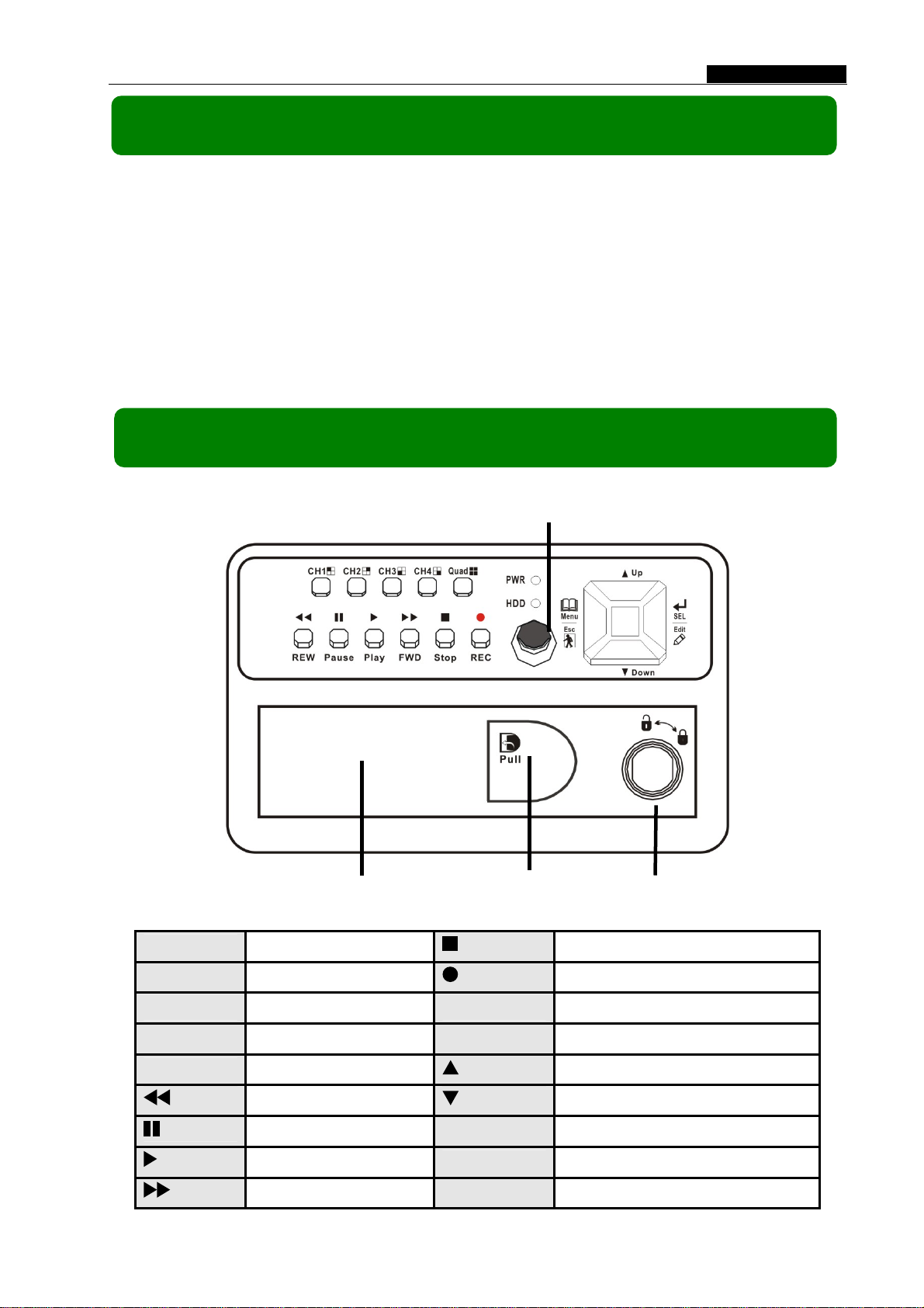
2.1 Front Panel
Chapter 2: Overview
Removable HDD Tray
IR Receiver
Finger Hole
HDD Lock
CH1
CH2
CH3
CH4
Quad
REW
Pause
Play
FWD
Channel 1
Channel 2
Channel 3
Channel 4
Quad View
Rewind
Pause
Playback Video
Fast Forward
Stop
REC
Menu/Esc
SEL/Edit
Up
Down
PWR
HDD
- 1 -
Stop Playing/Recording
Record
Enter / exit setup menu
Confirm Selection / Edit
Move up / left cursor
Move down / right cursor
Power indicator
Hard disk drive indicator
Page 5
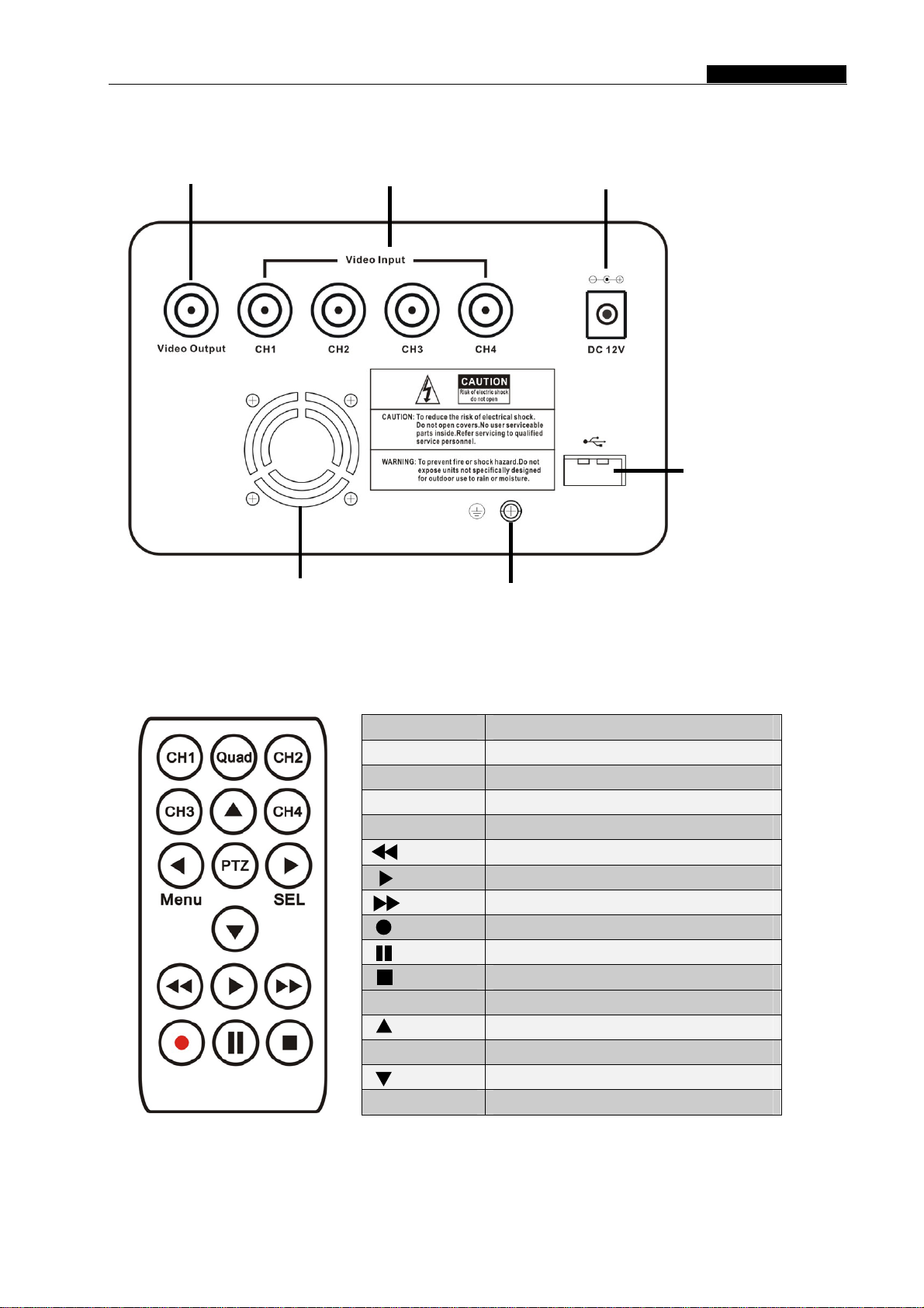
2.2 Rear Panel
1 BNC video output
Fan
4 BNC Video Inputs
Grounding Terminal
User Manual
Power Supply Input
USB
2.3 Remote Control
CH1 Select or enlarge Channel #1
CH2 Select or enlarge Channel #2
CH3 Select or enlarge Channel #3
CH4 Select or enlarge Channel #4
Quad Quad View (4 Camera View)
Rewind
Playback Recording
Forward
Record
Pause
Stop recording / playback
Menu Enter or exit setup menu
Move up / left cursor
SEL Select / modify item
Move down / right cursor
PTZ Not Used
- 2 -
Page 6
User Manual
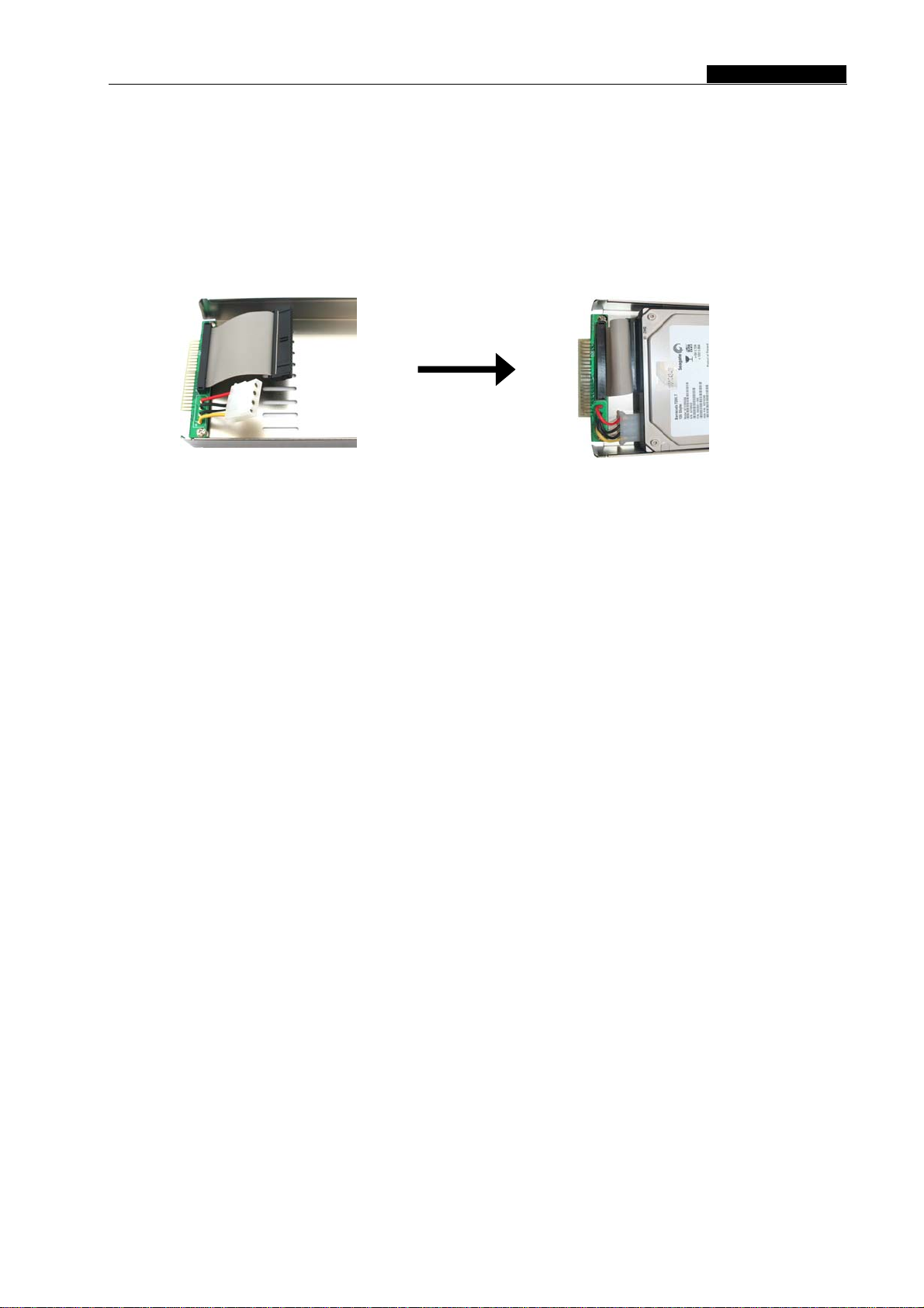
3.1 Installing Hard Drive
1. Unplug the power supply. Never install or uninstall HDD when DVR is on.
2. Pull the HDD tray from the unit using the finger hole.
3. Connect the power cord and data cable to hard disk drive.
Make sure the HDD is set to be MASTER according to the hard drive manual.
The 4 pin connection is the DC power cable for HDD, and the wider cable is the standard
hard drive IDE type connection.
4. Firmly insert the HDD tray into DVR body.
5. Lock the HDD tray.
Lock the caddy by turning the key clockwise.
If you need to unlock the tray, turn the key counter-clockwise.
CAUTION:
1. If HDD tray is not locked, the DVR system may not function properly.
2. Do not remove the HDD tray while the DVR is on.
3.2 Connecting Camera and Monitor
There are 4 camera inputs and 1 video output with BNC connectors (Refer to
2.2 Rear Panel).
3.3 Connecting the Power Supply
Please only use the power adapter supplied with the DVR. The standard power
supplied to the DVR is DC 12 Volt, 3.0 Amp.
- 3 -
Page 7

Chapter 4: Starting the DVR
4.1 Detecting Installed Hard Drive
Checking HDD ……
MASTER…
4.2 Recovering Lost Data
User Manual
After connecting the power, the system
will boot-up and detect the installed hard
drive.
On the screen it will show the hard drive
information. If no hard drive is detected,
check that the HDD is set to master and the
tray is locked.
RECOVER HDD?
04811-101735
(SELECT)YES/(MENU)NO
4.3 Restore Recording Feature
Power Error Detected
Restore Hard Disk (Master) OK
Restore REC Mode…………
OK
A power failure can cause data to be lost,
however the DVR system will automatically
recover lost data after power is reconnected.
If a power error occurs during
recording process, the system will
automatically resume recording after
power is reconnected.
- 4 -
Page 8

4.4 Main Screen
User Manual
When the DVR is turned on the
following display will appear with your
>
5.1 Setup Menu
connected cameras:
Upper left: Percentage of hard drive
space used
Middle: Channel number (CH1 through
CH4)
Bottom right: Date and Time
Bottom left: System/recording status.
(Refer to 6.1 Start Recording)
Chapter 5: DVR Setup
Menu
Directory
MAIN
MENU
CAMERA SELECT
RECORD SELECT
RESOLUTION
RECORD FRAME
VIDEO QUALITY
SCHEDULE SET
MISCELLANEOUS MENU
HARD DISK SET
VIDEO MODE
MOTION SET
AUTO RECORD
PASSWORD ENABLE
PASSWORD CHANGE
COLOR SET
TIME SET
FACTORY RESET
- 5 -
Page 9

User Manual
MAIN MENU
CAMERA SELECT 1234
RECORD SELECT 1234
RESOLUTION EACH
RECORD FRAME 25
RECORD QUALITY HIGH
SCHEDULE SET
MISCELLANEOUS MENU
HARD DISK SET
VIDEO MODE PAL
MOTION SET
FACTORY RESET
PRESS (UP,DOWN), ENTER (SELECT)
PRESS (MENU) TO EXIT
5.2 Camera Select
Menu]: Push to enter system menu
[
Up] and [ Down]: Move the cursor
[
[
SEL]: Select/modify settings
Menu]: Press exit/previous menu
[
The DVR system can display 4
cameras at once or you can limit the
number of cameras displayed to save
HDD space.
Press [
SEL] to modify setting, or
press [CH1], [CH2], [CH3] and [CH4] to
set each channel separately.
If a channel is disabled, the system will display “OFF” on the monitor; this
channel will not be recorded. (Refer to 5.3 Record Select)
5.3 Record Select
Manually set which channels are allowed to record.
Note: If no channels are selected, an error message will appear briefly on the
screen when record is selected. “1234” indicates all cameras are set to record.
- 6 -
Page 10

User Manual
5.4 Resolution
There are two modes of resolution for video recording:
EACH Mode:
The DVR compresses and records each video channel separately so you can
enlarge a single channel to full screen display and still be recording on all channels.
You can also record on specific channels, for example, you can turn off the record
function of CH1 and CH2 and then the system will only record video on CH3 and
CH4.
Press [CH1], [CH2], [CH3], and [CH4] enlarge relative channel to full screen
display.
In EACH Mode you can use the Auto Switch Function.
Auto Switch Function:
When the system is in live mode or recording mode, press and hold the
[QUAD] button for three (3) seconds to make each video channel enlarge to full
screen. Each camera will appear in full screen for three (3) seconds, including Quad
view. The switch will lasts until any button is pushed.
NOTE: Pushing the [ Stop] button will stop the switch feature but also may
stop the recording depending on Record Schedule Settings (5.7 Schedule Set).
QUAD Mode:
The DVR will compress and record all 4 video channels into one file however
recordings will be limited to quad view and you will be unable to view full screen
images in playback mode.
Auto Switch Function is not available in QUAD Mode.
5.5 Record Frame
Record frame indicates the frames or images recorded per second. More
frames per second gives smoother movement but uses more hard disk space.
The system default is 30fps (frames per second) for NTSC (PAL is 25fps).
This means the system will record 30 frames per second shared by the active
cameras. You can set frame rate for NTSC to 30,15,10,7,5,4,3,2,1 frames per second
(PAL is 25,12,8,6,4,3,2,1)
- 7 -
Page 11

y
User Manual
5.6 Record Quality
There are three levels of recording quality: High, Normal, and Low.
Higher quality records the best images but uses more hard drive space.
Record frame rate, record quality and available hard drive space will affect the
total recording time of the DVR system.
5.7 Schedule Set
You can preset video recording modes by Time and Motion Detection
Recording.
TTTMMMTTTTTTMMTTTTT--MMT
│ │ │ │ │ │ │ │ │
0 3 6 9 12 15 18 21 24
PRESS (UP,DOWN), ENTER (SELECT)
PRESS (MENU) TO EXIT
SCHEDULE SET
“-” No Recording
“T” Time (or manual recording: Default)
“M” Motion Detection Record
[
Up] and [ Down]: To move the cursor
[ SEL]: To modify record method
Numbers along bottom indicate the 24
hours of a da
For example:
If you want to record by motion detecton during 3 to 6 o’clock, set the time
points (3, 4, 5) to “M”; if you want to continuous record from 7 to 12 o’clock, set
the time points (7, 8, 9, 10, 11) to “T”.
Both of the recording methods need to be triggered by pressing the [REC]
button. After pressing [REC] button, if the schedule is set to “T” at that time, the
DVR will start to record immediately; if the schedule is set to be “M”, the DVR will
not record until motion (movement) is detected by system.
Force Record:
When the DVR is set to record by motion detection, the DVR will not record if
there is no motion. If you want to record immediately, please press and hold [REC
button for 3 to 5 seconds to begin manual recording.
- 8 -
]
Page 12

[
]
t
User Manual
5.8 Miscellaneous Menu-Auto Record
When this option is set to “ON”, the DVR will automatically continue with the
current Record Schedule if no actions occur for 5 minutes. If you choose “OFF”,
the DVR will not record until you press the [ REC] button.
5.9 Miscellaneous Menu-Password Enable
This DVR is equipped with password protection features. Set this feature to
“ON” to enable password protection. When this option is set to “ON”, you will be
required to enter a password if you want to stop recording or enter the menu.
System default password: Press [CH1] button six (6) times.
5.10 Miscellaneous Menu-Password Change
CURRENT
NEW
ONFIRM
C
PASSWORD : -----PASSWORD : -----PASSWORD : ------
All keys can be used as password
key except the [
which is used to exit.
If you forget your password,
please refer to 5.16 Factory Reset.
5.11 Miscellaneous Menu-Color Set
HUE: 0-99
SATURATION: 0-99
CONTRAST: 0-99
BRIGHTNESS: 0-99
Up] and [ Down]: move the cursor
[
[REW]: Increase value
[FWD]: Reduce value
[CH1-CH4, QUAD]: Select channel
Menu
: Exi
Menu] key,
- 9 -
Page 13

5.12 Miscellaneous Menu-Time Set
(
User Manual
∨
PRESS (UP,DOWN), ENTER (SELECT)
PRESS (MENU) TO EXIT
TIME SET
2008/08/08 20:08:08
5.13 Hard Disk Set
OVERWRITE ENABLED [YES]
MASTER HDD SIZ 120042MB
MASTER HDD USED 80865MB 77%
MASTER HDD FORMAT
SLAVE HDD SIZE N/A
SLAVE HDD USED N/A
SLAVE HDD FORMAT
PRESS (UP, DOWN), ENTER
(SELECT)
PRESS
HARD DISK SET
MENU) TO EXIT
Configure systemdate and time:
Up] and [ Down]: move the cursor
[
SEL]: modify the value
[
Menu]: exit and save
[
OVERWRITE ENABLED:
If you choose “YES”, recording
continues and overwrites oldest
recordings when the hard drive is full.
If you choose “NO", the
recording process will stop when the
hard drive is full.
HDD SIZE:
Indicates the total capacity of the hard drive installed in the DVR.
HDD USED:
Indicates the actual space used on the hard drive and the percentage of hard
drive space used.
HDD FORMAT:
Choose this option to delete all data on a hard drive.
You will be prompted to input your password when formatting the HDD.
Note: When you install a new hard drive in the DVR, please use this function to
format the hard drive for use with the DVR.
- 10 -
Page 14

5.14 Motion Set
m
MOTION RECORD TIME: 10
MOTION ALARM TIME: OFF
MOTION SET
PRESS (UP, DOWN), ENTER
(SELECT)
PRESS (MENU) TO EXIT
MOTION SET:
MOTION SET
User Manual
MOTION RECORD TIME:
This number indicates how many
seconds the motion detection recording
lasts after the DVR has detected motion.
MOTION ALARM TIME:
This number indicates how many
seconds the buzzer/alarm inside the DVR
will sound after the DVR has detected
motion.
CONT: Continuous alarm until press any
key is pressed when motion detected.
OFF: No alar
(SELECT)
MOTION DETECTION SET
>CHANNEL 1 SENSITIVITY 4
CHANNEL 2 SENSITIVITY 4
CHANNEL 3 SENSITIVITY 4
CHANNEL 4 SENSITIVITY 4
CHANNEL 1 AREA SET
CHANNEL 2 AREA SET
CHANNEL 3 AREA SET
CHANNEL 4 AREA SET
PRESS (UP, DOWN), ENTER
PRESS (MENU) TO EXIT
SENSITIVITY:
Use [
Up] and [ Down] button to
highlight the channel you want to modify
and press [
SEL] to adjust sensitivity of
motion detection on each channel.
High (1----------9, OFF) Low
When “OFF”, the channel will not
detect motion or trigger motion recording.
AREA SET:
Use [
press [
selected channel is divided into 144(12*12) blocks, press [REW] to move left,
Up] and [ Down] button to select the channel you want to modify and
SEL] button to enter the sensitive area of each camera. The picture of the
press [FWD] to move right, press[
down, press [
SEL] to set the highlighted block active or disabled.
Up] and [ Down] to move the cursor up and
When the block is transparent, it’s active or set to detect motion. When the
block is covered by a shadow, it is not active and motion will NOT be detected.
Make sure Record Schedule is set to Motion for the times required.
- 11 -
Page 15

4
User Manual
5.15 Video Mode
Select NTSC (North America) or PAL (Europe/Australia) video system.
5.16 Factory Reset
Press [ SEL] button to reset the DVR to factory defaults. The DVR will
reboot and all custom settings (including password) will be restored to default.
Caution: There is no confirmation dialog box for this selection after you
press [
SEL] button.
If you have forgotten your password and would like to reset, press [Pause]
button 10 times to reset DVR to factory default. Then the default password is now:
[CH1] button 6 times.
If you are unable to stop recording, you must unplug the power supply and
remove the HDD, then reboot the DVR and press [Pause] button for 10 times.
Chapter 6: Recording
6.1 Start Recording
Press [ REC] to start recording (as set in 5.7 Schedule Set).
DVR will display system information on screen.
5
1
2
3
R
1
R
3
6
7
R
2
R
8
EACH REC [M] (T) 2008/07/01 16:22:30
10%
4
- 12 -
Page 16

User Manual
1. Hard Drive Usage (Displayed as a percentage)
2. Recording symbol (channel is currently recording)
3. Camera Number
4. Record Mode (QUAD or EACH)
5. Status (REC, Play, FF1, FF2, FF3, REW, PAUSE)
6. HDD Info. ([M] Master Hard disk)
7. Record Schedule: (T) Time or Manual Record (M) Motion Detection (-) No
Recording
8. The date and time on the DVR
6.2 Stop Recording
Press [ Stop] button to stop recording. If you have already activated the
password protection, you will be prompted to input the password.
6.3 Recording Time on Hard Drive
System Quality Frame Rate 30 15 7 1
HIGH 20 K Bytes 58 117 251 1748
NTSC
System Quality Frame Rate 25 12 6 1
NORMAL 15 K Bytes 78 155 332 2330
LOW 12 K Bytes 97 194 416 2913
HIGH 20 K Bytes 70 146 291 1748
PAL
NORMAL 15 K Bytes 93 194 388 2330
LOW 12 K Bytes 117 243 485 2913
Estimated record time based on a 120GB Hard Drive (Quad Mode) in hours:
You can calculate and estimate record hours by below formula:
120 (G Byte) × 1024 (M Byte) × 1024 (K Byte)
Divided by:
15 (Kbyte/frame) × 7 (frame/sec.) × 60 (sec.) x 60 (min.)
Estimated time would be 332 Hours.
- 13 -
Page 17

User Manual
Chapter 7: Playback
Press [
During playback, press the [
Play] button to play the last recording.
Menu] button to list all recorded video clips
from the hard drive. Newest video will be listed at the top.
Press [
[
Play] button to start playback.
Up] and [ Down] to move the cursor and select an event, press
1. Starting time of the event 2. TIME: continuous record
3. MOTION: Motion Triggered event 4. FORCE: Force Record event
5. “*” marks un-played video recording
You can also play recorded video by searching the exact date and time as follows:
1. Press [FWD] button to change the select mode
2. Press [
3. Press [
4. Press [
Up] and [ Down] button to select date starting time or ending time
SEL] to edit time value
Play] to play the video
2008 /0 1 / 0 8 08 : 30 : 3 2 --- 2008/0 1 / 0 8 16 : 00 : 05
Search Date and Time
- 14 -
Page 18

User Manual
Chapter 8: USB Programming
Using the provided DVR PC Viewer software, you can connect the DVR Alert
to your PC to playback or backup footage.
8.1 PC Viewer Program
1. Insert the CD into your CD-ROM Drive
2. Open CD directory
3. Double click on the “PCViewerInstall.exe” file to install the PC Viewer software
4. Run the installed PC Viewer program
PC Viewer will detect the hard drive installed in the DVR automatically when
you connect the USB cable from DVR to PC.
8.2 Program buttons
1
2
3
4
5
6
7
8
9
10
15
18 16 17 11 12 13 14
- 15 -
Page 19

Item Remark
1. DVR event list Open event list recorded in DVR
2. Capture picture Save an image of current frame
3. Save video clip Save DVR’s video clip to PC in .mys/.avi file
5. Load video file saved in PC Load .mys file saved in PC
User Manual
6. DVR Mode*
7. PC Mode*
8. Channel selection keys CH1, CH2, CH3, CH4, QUAD
9. Playing scroll bar Video progress
10. Fast backward Play backward with fast speed
11. Previous frame Move to previous frame
12. Play backward Play backward with normal speed
13. Pause Pause playing
14. Play Play forward with normal speed
15. Next frame Move to next frame
16. Fast forward Play forward with fast speed
17. Volume scroll bar Not available for this model
18. Exit Exit PC Viewer
To switch working mode between PC viewer
mode and DVR viewer mode
DVR Mode: play video clips saved on DVR’s HDD.
PC Mode: play video clips (.mys file) saved on PC
8.3 PC Backup
Press button to open the DVR recorded event list and select an event.
Press
“.mys” files.
to begin backup. Backup video files can be saved as “.avi” files or
- 16 -
Page 20

Chapter 9: Specifications
ITEM DESCRIPTION NOTE
Video Format NTSC / PAL
Operation System None Stand-alone
Camera Input Channel 4 channel Composite BNC
Video Output Channel 1 channel Composite BNC
User Manual
Display Frame Rate
Recording Frame Rate
Recording Frame Rate
(Each Mode)
Record Mode Continuo us, Time Schedule, Motion Triggered.
Resolution
Video Compression Format
HDD Support Over 500G Byte ATA -100 Interface
Estimated Record Length
USB For PC playback & backup USB 2.0
Remote Control Included
NTSC 120 frames/second 4×30 frames/second
PAL 100 frames /second 4×25 frames/second
NTSC Max.30 fps (Quad) Quad Mode
PAL Max.25 fps (Quad) Quad Mode
NTSC
PAL
Display
Record
Each Channel =
30 fps ÷ Number of Cameras
Each Channel =
25 fps ÷ Number of Cameras
NTSC: 720×480
PAL: 720×576
NTSC: 320×112, 640×224
PAL : 320×136, 640×272
Motion-JPEG
(12-20K bytes/frame)
120GB Hard drive @ 7 frames per second @ Normal Quality
(120×1024×1024 Kbyte) ÷ ( 7×15×60×60 ) = 332 Hours
Max. 30 frames/s (Total)
Max. 25 frames/s (Total)
Quad: 640×224 (total)
Each: 640×224
Low : 12K Byte
Normal: 15K Byte
High : 20K Byte
Search
Dimension ( L × W × H ) 250 × 235 × 38mm
Method
Full Screen YES
Time、Date、Event
- 17 -
Page 21

System Connection Diagram
10.1
Chapter 10: Appendix
User Manual
DVR Accessories (included)
10.2
Power Cord
The shape of the plug might
be different from different
countries or regions.
Power Adaptor User’s Manual
Software CD
Remote Controller
USB Cable
- 18 -
 Loading...