

Page 1
™
Advanced security made easy
™
Wireless OutdoorCam™
Security Camera & Receiver
Operating Instructions
SW231-WCH / SW231-WDC
SW231-WOY / SW233-W2Y
SW233-W3Y / SW231-WCX
SW233-W2B
www.swannsecurity.com
SR231-W0Y-10006-110209
1
Page 2

Before You Begin
FCC Verifi cation:
NOTE: This equipment has been tested and found to comply with the limits for
Class B digital device, pursuant to part 15 of the FCC Rules. These limits are designed to provide reasonable protection against harmful interference in a residential installation. This equipment generates, uses and can radiate radio frequency
energy and, if not installed and used in accordance with the instructions, may
cause harmful interference to radio or television reception, which can be determined by turning the equipment off and on, the user is encouraged to try to correct the interference by one or more of the following measures:
· Reorient or relocate the receiving antenna
· Increase the separation between the equipment and the receiver
· Connect the equipment into an outlet on a circuit different from that to which
the receiver is connected
· Consult the dealer or an experienced radio/TV technician for help
IMPORTANT NOTE: Prohibition against eavesdropping
Except for the operations of law enforcement offi cers conducted under lawful
authority, no person shall use, either directly or indirectly, a device operated pursuant to the provisions of this Part for the purpose of overhearing or recording the
private conversations of others unless such use is authorized by all of the parties
engaging in the conversation.
WARNING: Modifi cations not approved by the party responsible for compliance
could void user’s authority to operate the equipment.
IMPORTANT SAFETY INSTRUCTIONS:
· Make sure product is fi xed correctly and stable if fastened in place
· Do not operate if wires and terminals are exposed
222
2 35
Page 3
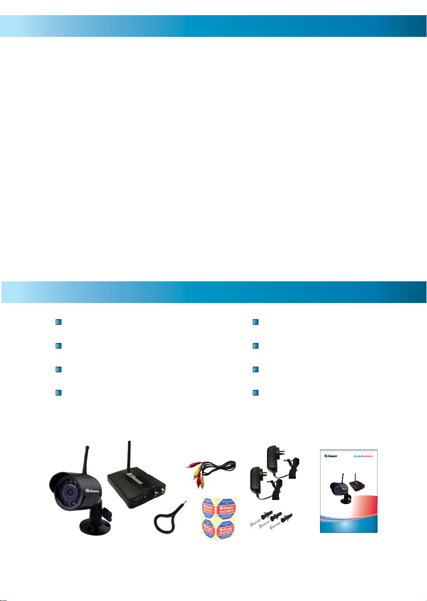
Table of Contents
Before You Begin 2
Table of Contents 3
Package Contents 3
Direct to TV Connection Guide 4
VCR / DVD Recorder Connection Guide 5
Viewing the Camera on a TV or VCR 6
Setting / Changing the Camera Channel 7
Selecting Channels on the Receiver 8
Setting the Loop Mode 9
Camera Placement & Interference 9
Troubleshooting Guide 10
Technical Specifi cations 11
Helpdesk / Technical Support Details 12
Warranty Information 12
Package Contents
Wireless OutdoorCam*
Receiver with Antenna
A/V Cable
Dip Switch Tool
Power Adapters
Operating Instructions
Security Stickers
Mounting Hardware
*Camera color may vary by region - 1, 2 or 3 Camera Packs
™
™
Advanced security made easy
Wireless OutdoorCam™
Security Camera & Receiver
Operating Instructions
SW231-WCH / SW231-WDC
SW231-WOY / SW233-W2Y
SW233-W3Y / SW231-WCX
www.swannsecurity.com
3
3
SR231-W0Y-10006-110209
Page 4
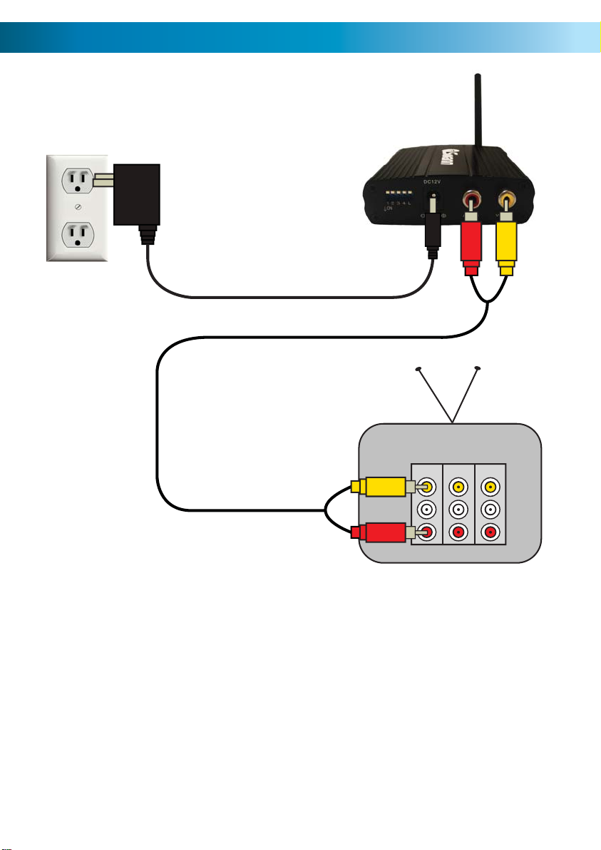
Direct to TV Connection Guide
he
he
Plug in the Receiver
Power Adapter
3
Connect the A/V Cable to the
RCA plugs on the back of the
1
receiver
Connect the other end of the
A/V cable to the INPUT on
2
the back of your TV
able to t
ack of t
INPUT 1 INPUT 3 OUTPUT
Note: if your TV or VCR does
not have a red RCA connection
use the white RCA connection
444
Page 5

he
VCR / DVD Recorder Connection Guide
Plug in the Receiver
Power Adapter
4
Input
Output
Connect the A/V Cable to the
RCA plugs on the back of the
1
receiver
Connect the other end of the
A/V cable to the INPUT on
2
the back of your VCR
able to t
ack of t
Note: if your TV or VCR does
not have a red RCA connection
use the white RCA connection
INPUT 1 INPUT 3 OUTPUT
Connect your VCR to your TV if it is not
already connected. Play a tape to ensure
3
it is connected properly
5
Page 6

Viewing the Camera on a TV or VCR
Viewing the Wireless OutdoorCam connected directly to a TV
1. Connect the Camera and Receiver as described in Connection Guide Direct
to TV on page 4
2. Plug in the Receiver and Cameras
3. Turn on your TV
4. Press the INPUT button on your TV’s Remote Control until your camera /
receiver appears on screen. The majority of TVs will label this button as INPUT,
A/V, SOURCE, AUX, TV/AV, Channel 0. If you are unable to change the input on
your TV, consult the TV’s instruction manual or contact your
Viewing and Recording the Wireless OutdoorCam on a VCR or DVD
Recorder
1. Connect the camera and receiver as described in the VCR/DVD Recorder
Connection Guide
2. Plug in the Receiver and Cameras
TV’s manufacturer.
3. Turn on your TV and VCR
4. Play a tape to confi rm your TV is on the correct channel, then press stop
5. Press the INPUT button on your VCR’s Remote Control until your camera /
receiver appears on screen. The majority of TVs will label this button as INPUT,
A/V, SOURCE, AUX, TV/AV, Channel 0. If you are unable to change the input on
your TV, consult the TV’s instruction manual or contact your
*The INPUT button is sometimes labeled Input, Source, Line In, L1, L2, AUX,
A/V, channel 0 etc. Consult the TV or VCR instruction manual for details about
changing input channels on your device.
6666
TV’s manufacturer.
Page 7

Setting / Changing the Camera Channel
The Wireless OutdoorCam operates in the 2.4GHz frequency range. It is capable
of transmitting on 4 channels. Follow the steps below to set or change the frequency channel of the camera.
Pull open the rubber fl ap on
the camera’s power cable
1
Locate the 2 dip switches
under the rubber fl ap
2
Use the Dip Switch Tool to fl ip
the switches to change the
3
camera’s transmitting channel
Set the camera channel as per the switch confi guration below. Do
not set multiple cameras on the same channel or interference will
4
appear on screen
Channel 1
1 2 1 2 1 2 1 2
Channel 2
Channel 3
Channel 4
77
Page 8

Selecting Channels on the Receiver
/V
p
r
Turning Channels ON or OFF
The Wireless Receiver is capable of receiving up to 4 separate channels. To turn on
channels move the dip switches on the receiver down to the ON position.
In the example below the receiver shows channel 1 is ON. No other channel will
appear other than Channel 1. Cameras will only appear on channels in the ON
position.
To activate channels move the channel
switch down to the ON position
1
23 4L
ON
If switches are up, they are set to OFF
and cameras will not appear on screen
Switching Between Active Channels
The front of the Wireless Receiver has 4 LEDs representing the 4 channels of the
receiver. When lit, the LED will indicate which channel is currently being displayed.
In the diagram below CH1 is lit up indicating Channel 1 will display on screen.
The Wireless Receiver allows you to manually switch between active channels by
pushing the SET button.
Note: The Wireless Receiver will only switch between active channels that have
been be set to the ON position as described above.
The SET button will manually switch
between active channels
The Receiver has 4 lights indicating
the 4 channels of the Receiver
888
Page 9

Setting the Loop Mode
The Wireless Receiver has a built in Loop Mode that will display cycle between all
active channels every few seconds.
To turn Loop Mode on, move the ’L’ or Loop switch down to the ON position. The
Receiver will automatically switch between active channels every few seconds.
When the Loop switch is ON the LED indicator on the front of the Receiver will
fl ash RED on the current active channel.
In this diagram Loop has been turned
on as well as Channels 1 and 4. The
1
23 4L
ON
Receiver will cycle from Channel 1 to
Channel 4 every few seconds.
Camera Placement & Interference
The Wireless OutdoorCam operates on 2.4GHz frequency. Some devices such as
wireless routers, microwaves, cordless phones can cause interference and affect
picture quality as they use the same frequency. If you are experiencing interference
or poor image quality try the following steps:
- move or orient the camera in a different location
- adjust or aim the receiver antenna
- limit the number of walls, fl oors between the camera and receiver as this can
dramatically alter picture quality
- dense materials such as concrete or metal will impede the wireless signal; move
the camera and/or receiver away from dense materials
- if possible keep the camera and receiver away from or move confl icting devices
such as wireless routers, microwaves, cordless phones
- make sure all cameras are set to different camera channels
- disconnect all other wireless devices to fi nd out which is causing the problem and
adjust your setup accordingly
- analog wireless cameras are not recommended for use with DVR systems; if you
are looking for a wireless camera solution for recording purposes see the digital
wireless ADW-300 (SW233-ADW) which will not suffer from interference
- some wireless signals may originate from nearby homes or businesses; in this case
a wired camera may be necessary
9
Page 10

Troubleshooting Guide
Problem: I can’t see the camera or receiver on my TV.
Solution: Ensure the camera and receiver are plugged in and the TV or VCR is
tuned to the correct input channel as described on Page 6.
Problem: All I can see at night is a white image.
Solution: The camera’s infrared LEDs shine invisible light that refl ects off surfaces
such as glass causing white light. Place the camera on the other side of windows
or place lens of camera fl ush against the window to try to improve the night
vision or place the camera in a well lit area.
Problem: I keep getting interference in my home or business.
Solution: The Wireless OutdoorCam operates on the 2.4GHz frequency like
many devices such as wireless routers, cordless phones, microwaves. If possible
keep the cameras and receivers away from these devices.
Problem: Motion detection on my DVR keeps recording interference from my
cameras.
Solution: Analog cameras such as the Wireless OutdoorCam are not
recommended for use with DVRs due to potential interference from other
devices. We recommend using wired cameras or the ADW-300 Digital Wireless
(SW233-ADW) camera that does not suffer from interference.
Problem: The picture keeps changing from one camera to the next.
Solution: The receiver is in Loop Mode. On the receiver move the ‘L’ switch up
to the Off position.
Problem: I only see 1 or 2 of my cameras when I press the Set button.
Solution: Channels on the receiver are turned off. Move the switches down to
the ON position to activate all cameras.
Problem: When I try to power the camera with a battery the image stops
transmitting after only a couple of hours.
Solution: This camera requires a constant supply of power to operate. Batteries can be used for temporary testing, placement purposes but mains power is
recommended for a long term solution.
101010
Page 11

Technical Specifications
Video
Image Sensor 1/3” CMOS
Video Quality 380 TV Lines
Number of Effective Pixels NTSC: 510 x 492 / PAL: 628 x 582
Electronic Shutter 1/60 - 1/15,000 NTSC / 1/50 - 1/15,000 PAL
Signal / Noise Ratio > 48dB
White Balance Automatic
Gain Control Automatic
Backlight Compensation Yes
Day/Night Mode Color during the day / Switches to B&W at night
Minimum Illumination 0 Lux (IR On)
Lens 6mm
Viewing Angle 53 degrees
Night Vision
Night Vision Distance Up to 26ft / 8m
Number of infrared LEDs 11
Wireless
Digital or Analog Analog
Max Transmission Range 165ft / 50m
Typical Range 65ft / 20m
Frequency 2.4GHz
Transmission Channels 4
General
Indoor/Outdoor Indoor or Outdoor
Operating Power DC 12V
Operating Temperature -10°C ~ 50°C / -14°F ~ 122°F
Body Construction Aluminum
Dimensions Camera & Stand 5.1” x 2.0” x 2.0” / 130mm x 50mm x 50mm
Weight – Camera & Stand 8.6oz / 245g
Dimensions Receiver 1.0” x 3.1” x 4.3” / 25mm x 80mm x 110mm
Weight – Receiver 6.5oz / 185g
11
11
Page 12

Helpdesk / Technical Support Details
Swann Technical Support
All Countries E-mail: tech@swannsecurity.com
Telephone Helpdesk
USA toll free
1-800-627-2799
(Su, 2pm-10pm US PT)
(M-Th, 6am-10pm US PT)
(F 6am-2pm US PT)
USA Exchange & Repairs
562-777-2551
(M-F, 9am-5pm US PT)
See http://www.worldtimeserver.com for information on time zones and the
current time in Melbourne, Australia compared to your local time.
AUSTRALIA toll free
1300 138 324
(M 9am-5pm AUS ET)
(Tu-F 1am-5pm AUS ET)
(Sa 1am-9am AUS ET)
NEW ZEALAND toll free
0800 479 266
INTERNATIONAL
+61 3 8412 4610
Warranty Information
Swann Communications USA Inc.
12636 Clark Street
Santa Fe Springs CA 90670
USA
Swann Communications warrants this product against defects in workmanship and material
for a period of one (1) year from it’s original purchase date. You must present your receipt
as proof of date of purchase for warranty validation. Any unit which proves defective during
the stated period will be repaired without charge for parts or labour or replaced at the sole
discretion of Swann. The end user is responsible for all freight charges incurred to send the
product to Swann’s repair centres. The end user is responsible for all shipping costs incurred
when shipping from and to any country other than the country of origin.
Swann Communications PTY. LTD.
Building 4, 650 Church Street,
Richmond, Victoria 3121
Australia
The warranty does not cover any incidental, accidental or consequential damages arising
from the use of or the inability to use this product. Any costs associated with the fitting or
removal of this product by a tradesman or other person or any other costs associated with
its use are the responsibility of the end user. This warranty applies to the original purchaser
of the product only and is not transferable to any third party. Unauthorized end user or
third party modifications to any component or evidence of misuse or abuse of the device will
render all warranties void.
By law some countries do not allow limitations on certain exclusions in this warranty. Where
applicable by local laws, regulations and legal rights will take precedence.
121212
© Swann Communications 2009
 Loading...