

Page 1

Indesit Company UK Ltd
© 2015 Reg. Office: Peterborough PE2 9JB Registered in London: 106725
Service
Information
SWAN brand
Entry Level
ELECTRONIC
CONDENSER
TUMBLE DRYERS
Models Covered:
STCL407WUK 87207
STCL407BUK 87208
STCL408WUK 87209
STCL408BUK 87210
5407837 Issue 2 July 2015
SM003992 ~ C00307711
PLEASE NOTE:
These models do not
display Fault Codes if a
Fault occurs.
Refer to the Fault Finding
details on page 6.
Page 2

2 of 34
Service Manual UK
Indesit Company
English
SAFETY NOTES & GENERAL SERVICING ADVICE
1. This manual is NOT intended as a comprehensive repair/maintenance guide to the appliance.
2. It should ONLY be used by suitably qualified persons having technical competence applicable
product knowledge and suitable tools and test equipment.
3. Servicing of electrical appliances must b e undertaken with the applia nce disconnected (unplugge d)
from the electrical supply.
4. Servicing must be preceded by Earth Continuity, Earth Resistance and Insulation Resistance
checks.
5. Personal safety precautions must be taken to protect against accidents caused by sharp edges on
metal and plastic parts.
6. After servicing the appliance must be rechecked for Electrical Safety. In the case of appliances
which are connected to a water supply (i.e.: Washing Mach ines, Dishwashers & Foo d Centres etc.)
checks must be made for leaks from seals gaskets and pipe work and rectification carried out where
necessary.
7. It can be dangerous to attempt 'DIY' repairs / maintenance on complex equipment and the Company
recommends that any problem with the appliance is referred to its own Service Organisation.
8. Whilst the Company has endeavou red to ensure the accuracy of the data within thi s publication they
cannot hold themselves responsible for any inconvenience or loss occasioned by any error within.
SERIAL NUMBER / INDUSTRIAL CODE EXPLANATION
Serial Number Example
1 10 02 0895
Four remaining digits = Build number that day 895
th
built
Third two digits = Day of manufacture 2
nd
of month
Second two digits = Month of manufacture October
First digit = Year of manufacture 2011
Industrial Code Example
37 24455 0010
Last four digits = 0000 original production.
Second five digits = COMMERCIAL CODE*
First two digits = Factory of origin
* Vital for correct model information and system identification
Other numbers denote major production changes
Page 3

3 of 34
Indesit Company
Service Manual UK English
INDEX
Safety & Servicing Notes . . . . . . . . . . . . . . . . . . . . . . . . . . . . . . . . . . . . . . . . . . . . . . . . . . . . . . . . 2
Serial Number / Industrial Code Explanation. . . . . . . . . . . . . . . . . . . . . . . . . . . . . . . . . . . . . . . . 2
Index. . . . . . . . . . . . . . . . . . . . . . . . . . . . . . . . . . . . . . . . . . . . . . . . . . . . . . . . . . . . . . . . . . . . . . . . . .3
Production Changes. . . . . . . . . . . . . . . . . . . . . . . . . . . . . . . . . . . . . . . . . . . . . . . . . . . . . . . . . . . . .3
Model Matrix . . . . . . . . . . . . . . . . . . . . . . . . . . . . . . . . . . . . . . . . . . . . . . . . . . . . . . . . . . . . . . . . . . 4
Energy Information. . . . . . . . . . . . . . . . . . . . . . . . . . . . . . . . . . . . . . . . . . . . . . . . . . . . . . . . . . . . . .4
Specifications . . . . . . . . . . . . . . . . . . . . . . . . . . . . . . . . . . . . . . . . . . . . . . . . . . . . . . . . . . . . . . . . . .5
Fault Finding / Test Cycles . . . . . . . . . . . . . . . . . . . . . . . . . . . . . . . . . . . . . . . . . . . . . . . . . . . 6 - 10
Thermistor Table. . . . . . . . . . . . . . . . . . . . . . . . . . . . . . . . . . . . . . . . . . . . . . . . . . . . . . . . . . . . . . .11
Heater Connection Details . . . . . . . . . . . . . . . . . . . . . . . . . . . . . . . . . . . . . . . . . . . . . . . . . . . . . . .12
Wiring Diagram . . . . . . . . . . . . . . . . . . . . . . . . . . . . . . . . . . . . . . . . . . . . . . . . . . . . . . . . . . . . . . . .13
Installation. . . . . . . . . . . . . . . . . . . . . . . . . . . . . . . . . . . . . . . . . . . . . . . . . . . . . . . . . . . . . . . . . . . 14
Dryer Care . . . . . . . . . . . . . . . . . . . . . . . . . . . . . . . . . . . . . . . . . . . . . . . . . . . . . . . . . . . . . . . . 15 - 16
Dryer Overview . . . . . . . . . . . . . . . . . . . . . . . . . . . . . . . . . . . . . . . . . . . . . . . . . . . . . . . . . . . . 17 - 19
Dryer Function . . . . . . . . . . . . . . . . . . . . . . . . . . . . . . . . . . . . . . . . . . . . . . . . . . . . . . . . . . . . 20 - 23
Component Description . . . . . . . . . . . . . . . . . . . . . . . . . . . . . . . . . . . . . . . . . . . . . . . . . . . . . 24 - 25
Programme Guide. . . . . . . . . . . . . . . . . . . . . . . . . . . . . . . . . . . . . . . . . . . . . . . . . . . . . . . . . . . . . 26
Control Board Programming . . . . . . . . . . . . . . . . . . . . . . . . . . . . . . . . . . . . . . . . . . . . . . . . . 27 - 28
Dismantling - Condenser . . . . . . . . . . . . . . . . . . . . . . . . . . . . . . . . . . . . . . . . . . . . . . . . . . . . 29 - 33
Production Changes
February 2015 Settings File updated to fix Dryer not heating when used in locations with a low
ambient temperature (Garages / Outhouses etc.)
Thermistor Resistance value chart added to this document (Issue 3 ) .
Page 4
4 of 34
Service Manual UK
Indesit Company
English
Example Energy Information - STCL408W / STCL408B
This household tumble drier is a Condenser
The weighted Annual Energy Consumption (AEc)* kWh 1) 627.8
This household tumble drier is a Automatic
Energy consumption full load; Edry - kWh 2) 5.33
Energy consumption partial load; Edry½ - kWh 2) 2.83
Power consumption: o-mode (Po) - Watts 0.42
Power consumption: left-on mode (Pl) - Watts 2.24
Prog. Time - weighted (Tt) full & partial load - minutes 3) 112
Full load (Tdry) - minutes 151
Partial load (Tdry½) - minutes 82
weighted (Ct) full & partial load 3) 71
full load (Cdry) 71
partial load (Cdry½) 71
Airborne acoustical noise emissions - dB(A) re 1 pW 68.0
Programme time in minute, for program “Synthetics” full load 85
Partial load for program “Synthetics” N/A
Average condensation eciency - %
1) "Standard cotton” at full and partial load is the standard programme to which the
information in the label and the che relates. The standard cotton program is
suitable to dry at cupboard level (0%) cotton laundry and is the most ecient
programme in terms of energy consumption. Partial load is half the rated load.
2) based on 160 drying cycles of the standard cotton programme at full and partial
load, and the consumption of the low-power modes. Actual energy consumption
will depend on how the appliance is used.
3) Weighted average of 3 cycles at full load and 4 cycles at half load.
R
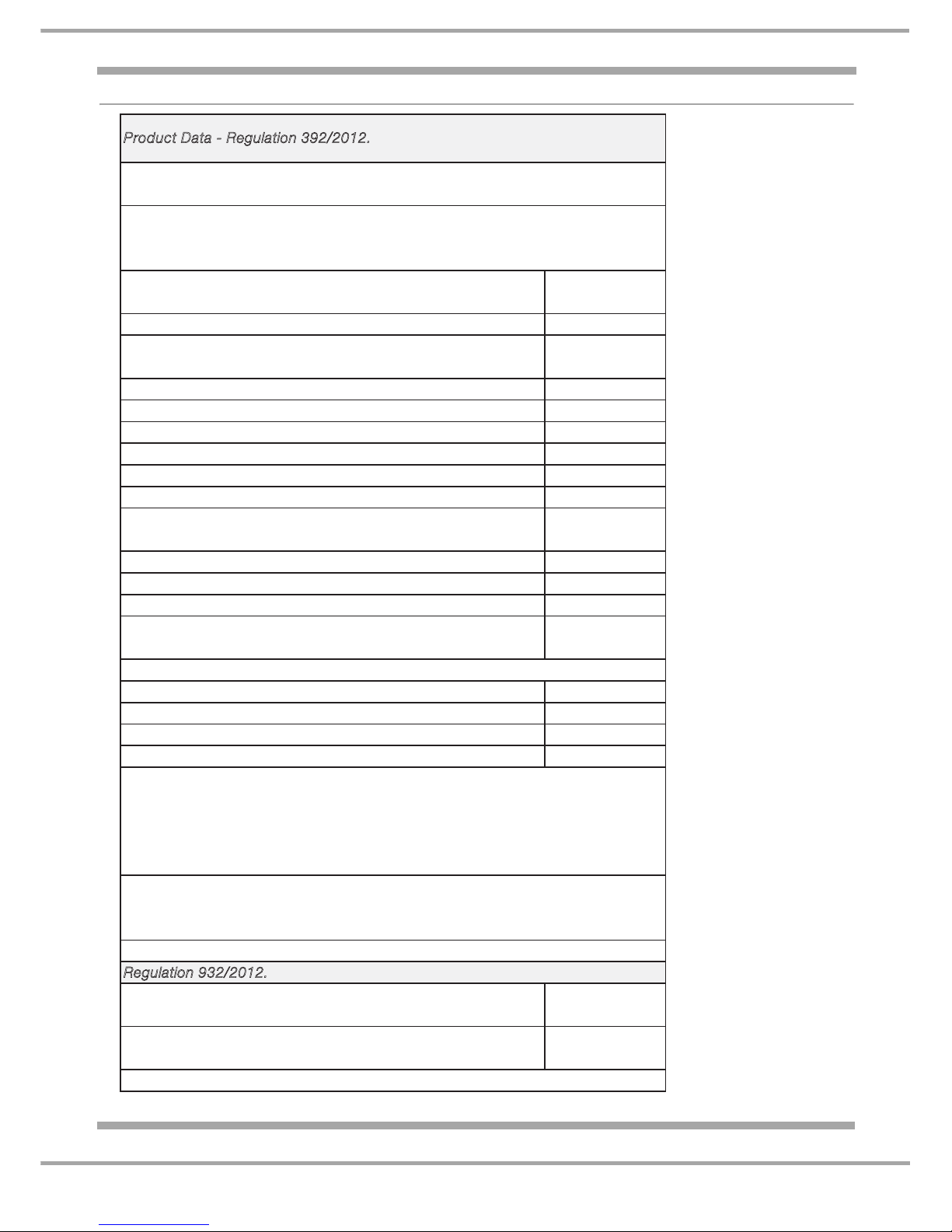
egulation 93 2 /2 0 12.
Energy consumption in kWh, for program “Synthetics” full load 1.93
Energy eciency class on a scale from A+++ (low consumption)
to D (high consumption)
C
Duration of the 'left-on mode' for power management system minutes
30
Condensation eciency class on a scale from G (least ecient) to
A (most ecient)
C
P
roduct Data - R egulation 392/2012.
Brand
Swan
Model
STCL 408W (UK) STCL 408B (UK)
Rated capacity of cotton laundry for the "standard cotton
programme" at full load - kg
8.0
Page 5

5 of 34
Indesit Company
Service Manual UK English
SPECIFICATIONS
Introduction Date August 2014
Features Electronically controlled tumble dryer comprising an combined interface
and control module fitted to the rear of the dashboard.
Country of Origin UK
Dimensions
Height 850 mm
Width 595 mm
Depth 623 mm
Net Weight 36.87 kg
Colour White
Energy Class B or C Depending on model (2012 Energy Label Regulations)
Noise Level 69db
Power Consumption
Left On 2.24 watts
Off Mode 0.42 watts
Drum Volume 112 Litres
Electronics Stripped Arcadia
Heater High Heat 2.3 kW
Heater Controls Variable using Electronic Controls and sensors
Sensing Levels 3 or 5 depending on model.
Control Thermostats Cycling Thermostat 120
°C
One Shot Thermostat 143 °C
Motor Type 362/363-Single Phase Capacitor run 2 pole Induction Motor 2800 rpm
Capacitor 8.5uF
Approvals CE, IMQ
Page 6
6 of 34
Service Manual UK
Indesit Company
English
FAULT FINDING
FAULT CODES
These models DO NOT display Fault Codes when the dryer develops a fault.
However an Auto Test feature is available to help diagnose faults.
Preliminary Checks:
Before performing any tests ALW AYS check that the W ater Cont ainer is empty and that the Condenser
Unit and the Drum Filter are NOT blocked with fluff or lint, as this may be the cause or partial cause of
the of the fault.
Auto Test
If a Fault is detected the dryer will not move on to the next phase of the test, but will perform the
following sequence:
> Beep Once
> Pause for 30 Seconds
> Beep 3 Times
> The End LED will display
This will Indicate the dryer has a Fault, but it will not indicate the exact cause of the problem.
Observing at which phase the auto test ends gives an indication of the type of fault and cause.
See the information on the following pages.
2
Water container
Condenser Unit
Condenser cover
Catches
Filter
Handle
Air intake
Ta p
Rear
Front
Condenser
unit
Page 7
7 of 34
Indesit Company
Service Manual UK English
Auto Test Sequence
Before Starting the Auto Test, make sure the Water Container is empty, the Filter and
Condenser are Clear of fluff or lint.
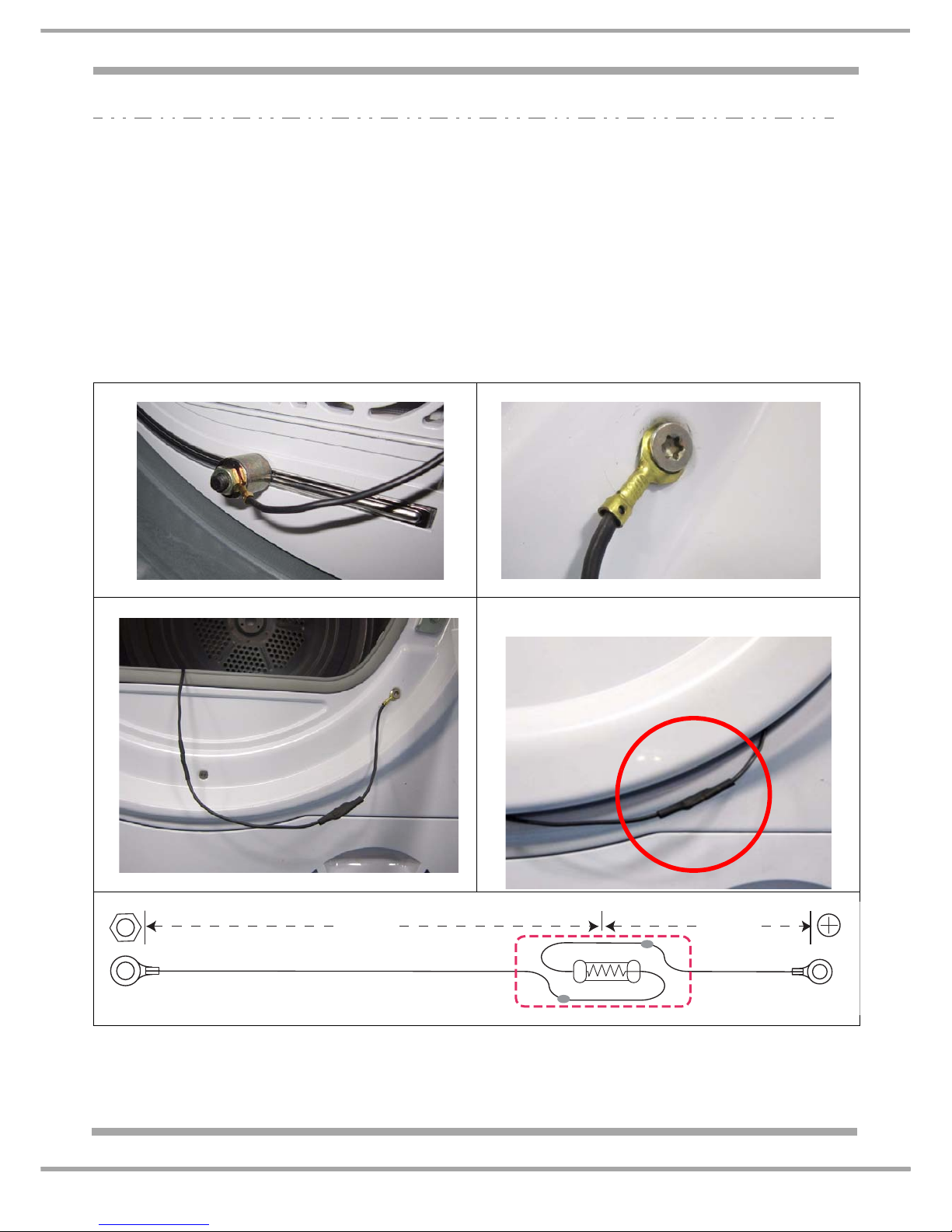
Auto Test - Preparation:
If you are including the Conductivity Sensor Test when running the test procedure:
1. Attach the magnetic end of the 270 K ohm test lead to the metal strip conductivity sensor inside
the drum.
2. Connect the ring terminal end to an earth point on the cabinet of the machine. (The Ai r Duct fixing
screw is recommended).
3. After attaching, check Earth Continuity between this ring terminal and the mains power plug Earth
pin on or the metal rear panel of the dryer, using a multimeter.
The continuity resistance reading should be 1 ohm or less.
Magnet fixed to sensing strip inside the drum Ring terminal end fixed under air duct screw
Routing of wire and resistor. Safe position of 270K ohm resistor
assembly with door closed
270K
2W
450 mm
180 mm
Magnet Screw fixing
Page 8

8 of 34
Service Manual UK
Indesit Company
English
AUTO TEST - CONDENSER DRYERS
SAFETY WARNING !
When performing the Auto Test you will need to remove the top cover of the Dryer while
Electrical power is still applied.
To avoid the risk of electric shock, during this sequence you MUST make certain no
persons have any contact with the LIVE area around the Mains Terminal Block (cable entry
position) or main Power module behind the Console.
Preparation:
1. Remove the 2 screws securing the top cover to allow its removal when required during the test
sequence.
2. If necessary fit the Magnetic Test resistor. See page 7 for details.
To Enter Auto Test Mode - Condenser Models
1. The dryer must be plugged into the electricity supply with the Programme Selector set to the
“OFF” Position.
2. Turn the Selector Clockwise to Programme 1. Wait for the LED’s to turn OFF.
3. Push the Delay Option Button once.
4. Turn the Selector Clockwise to Programme 2.
5. Push the Delay Option Button once.
6. Turn the Selector Anti-Clockwise to Position 15.
7. Push the Start Button once.
This starts the test, indicated by the drum rotating clockwise fo r a short period - approximately
7 -8 seconds.
Note: If after starting the Auto Tes t and the drum has not Pause d within 15 seconds, the a uto test
has not been entered successfully, turn the control Knob to OFF, and repeat the above sequence.
TEST SEQUENCE - for a CONDENSER DRYER which has no detectable Faults
1. The Drum Rotates Clockwise for about 7 or 8 seconds.
Pause.
At this point remove the top cover. Remove the Water Bottle and pour 300 ml of water into the
Water Bottle support. (This will operate the Float Switch at the base of the dryer).
2. Refit the Water Bottle (if the Water Bottle is not replaced the test will fail at this point).
3. The dryer will pause until the Float Switch has moved to the full position.
The drain pump will turn on and the drum will rotate Clockwise for about 15 seconds.
The water that was poured into the support (filling the pump) will be pumped into the water bottle.
Pause for 5 seconds.
4. The Drum Rotates Anti-Clockwise with the Heater On (both elements) until the Rear Thermistor
detects a temperature Rise, - the heater then turns OFF and the drum continues to rotate.
Pause for 5 seconds.
5. The Drum Rotates Clockwise with the Heater On until the Front Thermistor detects a temperature
change, the Heater turns Off and the drum continues to rotate.
Long Pause.
6. 3 Beeps then the END LED Illuminates.
7. Test Ends.
Page 9

9 of 34
Indesit Company
Service Manual UK English
TEST SEQUENCE - for a CONDENSER DRYER which has a Fault,
1. The Drum rotates clockwise for about 7 to 8 seconds
Step Phase: Float switch operation and Drain Pump operation
At this point remove the top cover. Remove the Water Bottle and pour 300 ml of water into the
Water Bottle support. This will operate the Float Switch at the base of the dryer.
2. Refit the Water Bottle (if the Water Bottle is not replaced the test will fail at this point).
3. The dryer will pause until the Float Switch has moved to the full position.
The drain pump will turn on and the dr um wi ll r otate Clockwi se for abou t 15 se conds - ac tual Ti me
depends on quantity of water in the base reservoir.
The water that was poured into the support (filling the pump) will be pumped into the water bottle.
Pause 5 seconds.
Step Phase: Heater Operation and Rear Thermistor Temperature Check
4. Drum Rotates Anti-Clockwise with the Heater On (both elements) until the Rear The r mistor
detects a temperature Rise, - the heater then turns OFF and the drum continues to rotate for a
short period.
Pause for 5 seconds.
Step Phase: Heater Operation and Front Thermistor Temperature Check
5. Drum turns Clockwise with Heater On (both elements), until the Front Thermistor detects a
temperature change.
6. Heater will Turn Off, the Drum will continue for a few minutes..
Step Phase: Conductivity Sensor Check (only applies if magnetic resistance is being used)
8. Test Ends
If the pump is faulty or a there is a blockage in the hose or a pump wiring fault, the
Water container will not fill with water at this point, and the drum wil l continue to turn
for approx. 3 minutes, then the dryer beeps, paus es fo r 30 se con ds , bee ps 3 times
then the Test Ends.
If the Rear Thermistor, Thermostat or Heater is Open Circuit (both Elements) or
disconnected the Test Cycle will finish at this point - then the dryer beeps, pauses
for 30 seconds, beeps 3 times then the Test Ends.
If the Front Thermistor, is Open Circuit or disconnected the Test Cycle will finish at
this point - then the dryer beeps, pauses for 30 seconds, beeps 3 times then the
Test Ends.
7.
With Magnetic test resistor fitted
and Sensor Circuit OK
Without Magnetic test resistor fitted
OR fitted but Sensor Circuit not OK
Long Pause,
3 Beeps,
End LED is Illuminated.
Pause,
Beep,
Long Pause,
3 Beeps,
End LED is Illuminated.
Page 10

10 of 34
Service Manual UK
Indesit Company
English
DRYER OPERATION CHECK - Condenser Models
When Checking Heater, Drum Action or Thermistor Operation, you are advised to use a Timed
Programme.
When Sensor Programmes are used, after the module has estimated the weight of the clothes and the
cycle time required to dry the clothes, the Dryer will start to reverse tumble.
Note: This weight and estimated drying time are calculated by the module which monitors the front
thermistor temperature increase in the Front Air Duct over a period of time.
For example, a small load will allow a faster temperature rise at the front thermistor.
A large load would cause the temperature to rise more slowly.
Drum
When set to a Timed Programme the machine will reverse for a short period approximately every 5
minutes.
Heater
Faulty or Disconnected Thermistors (Front and Rear) and the associated wiring will cause the
machine not to heat. (If an Auto Cycle is used the dryer may operate at ½ Heat, depending on cycle
used).
In these instances the machines will complete the Cycle without Heating with no indication to the user,
other than the load will be cold and wet at the end of the cycle.
One Element Open Circuit - Dryer works at 1.15 kW and dries normally taking slightly longer to
complete the cycle.
Thermistors
Rear Thermistor (Located on Heater Frame) next to the Cycling and One-Shot cut-outs.
Page 11
11 of 34
Indesit Company
Service Manual UK English
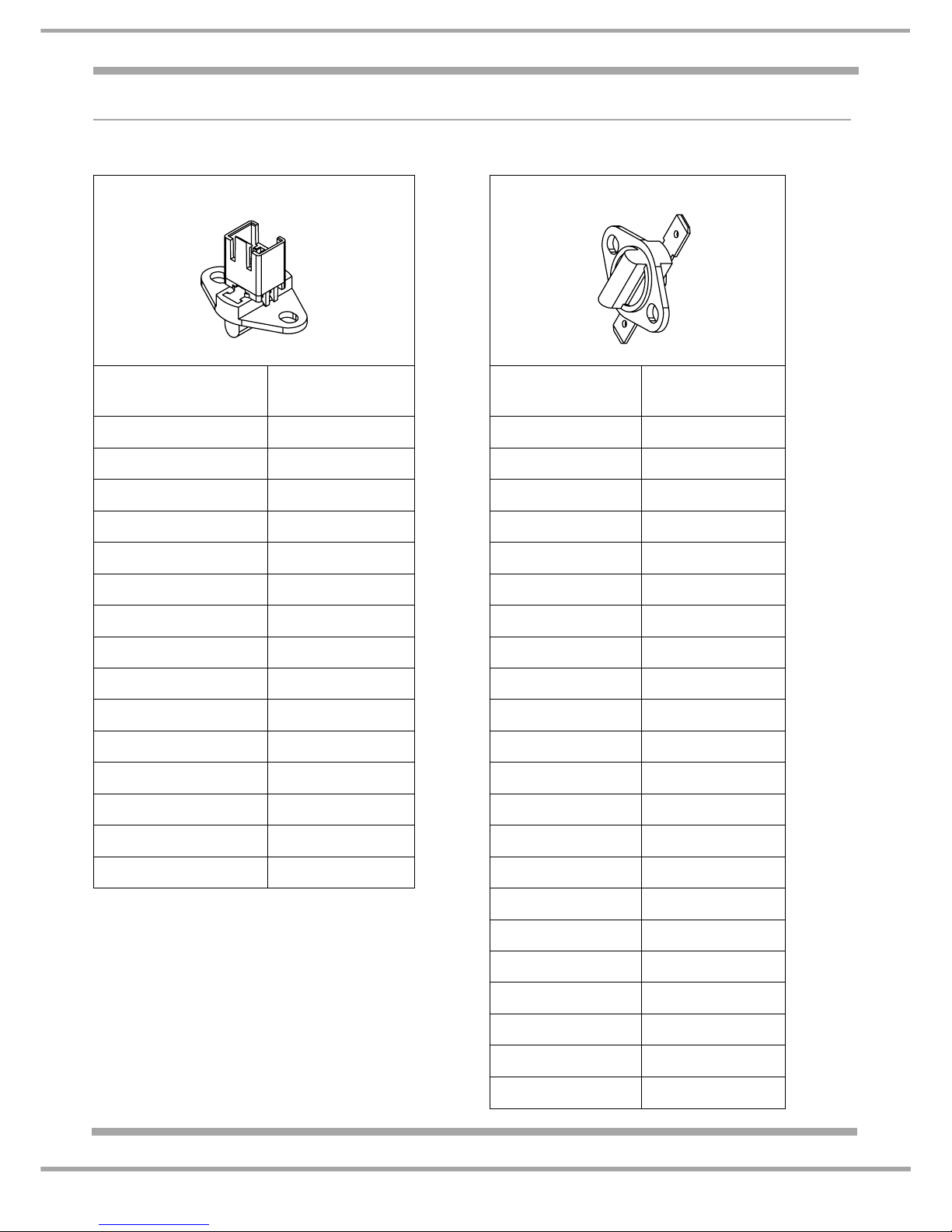
Thermistor Tables
When testing these Thermistors make sure you have selected the CORRECT resistance range on
your test meter for the value you expect to see. The resistance value varies with temperature.
FRONT THERMISTOR REAR THERMISTOR
Temperature
°C
Resistance
KΩ
Temperature
°C
Resistance
KΩ
-20 462.89 -20 958.78
-10 268.29 -10 549.14
0 160.39 0 324.98
10 98.66 10 198.37
20 62.32 20 124.37
25 50.00 25 100.00
30 40.35 30 80.544
40 26.73 40 53.173
50 18.096 50 35.878
60 12.496 60 24.768
70 8.792 70 17.418
80 6.296 80 12.442
85 5.361 85 10.582
90 4.583 90 9.0436
100 3.388 100 6.6843
110 5.0111
Example: Front Thermistor
If the ambient temperature where
you are testing is 15°C you would expect to get a
reading of approximately 80.40KΩ.
(If the thermistor has warmed up because of
handling or operation of the dryer then the meter
reading will be a lower value)
The Rear Thermistor is a different component wi th
a different specification - refer to the chart
120 3.8064
125 3.3330
130 2.9262
140 2.2754
150 1.7891
Page 12

12 of 34
Service Manual UK
Indesit Company
English
Heater Connection Details
Cable Colours
Heater / Thermistor Connector Plug
Always fit a cable
tie to secure the
Heater connectors
together.
dynamic/upper heater
brown
orange
orange
orange
white
link
hot/rear NTC
5
4
3
2
1
red
red
static/lower heater
one shot
cycling
cut-out
thermostat
cycling one shotthermistor
Page 13

Indesit Company
13 of 34
Service Manual UK English
WIRING DIAGRAM - Entry Level CONDENSER Models
231
65321
4
blue
red
black
1
2
cycling
thermostat
one shot
cut-out
door switch
brown
brown
orange
orange
orange
231
231
front NTC
hot/rear NTC
float switch
drain pump
PSC Motor
with protector
3
4
blue
red
red
red
black
Capacitor
main connection
with suppressor
L
N
E
brown
blue
54321
red
red
white
red
blue
white
Drum assy
sensing
strip
1
2
3
132
orange
blue
blue
red
red
CONNECTOR
ON BOARD WAYS WIRES DESCRIPTION
CN1 5 5 I2C
CN2 4 4 UART BPM motor
CN3 1 1 earth
CN4 1 1 sensi ng
strip
CN5 6 4 drain pump
- Ňoat switch
CN6 3 2 hot/rear NTC
CN7 3 2 front NTC
CN9 3 3 PSC motor
CN10 3 3 heate r
CN11 4 4 suppressor - doorsw itch
1
2
HARNESS INDESIT CODE DESCRIPTION
H1 21023259100 motor
drain pump
Ňoat
switch
front NTC
hot
NTC
H2 16002965300 Sensingstrip
H3 16002965200 Earth
H4 16002974000 Heater
H5 16002973900 s
uppressor -
door sw itch
green/yellow
static/lower heater
dynamic/upper heater
Heater cover assy
cw
ccw
4,8
160029741
160029743
160029744
160029742
black
160029653
160029652
160029739
160029738.00
CN1CN2
CN3
CN4
CN5CN9 CN6
CN7
CN10
CN11
CONDENSER DRYER
Page 14

14 of 34
Service Manual UK
Indesit Company
English
INSTALLATION
The dryer MUST be located away from gas stoves,
hobs or heaters.
If the dryer is located under a work surface, there
must be a 10 mm gap around any top or above the
dryer and a minimum 15 mm space along each side.
This is to ensure correct air circulation.
CONDENSER DRYERS
Draining the dryer into an Internal Drain
If the dryer drains into an external drain, the water container will not need to be regularly emptied.
The height of the drain must be less than 1 metre from the bottom of the dryer.
Remove the existing hose from the position shown, Fig. 1. Fit a suitable length of hose (Part No.
C00279043) to the location shown in the photo (Fig. 2).
Confirm the hose is not squashed or kinked when the dryer is in its installed position.
15 mm
15 mm
10mm
Remove this hose
Fig.1
Outlet Spigot
Fig.2
New drain hose fitted
Fig.3
Page 15

15 of 34
Indesit Company
Service Manual UK English
LOOKING AFTER THE DRYER
FLUFF FILTER
The fluff filter MUST be cleaned after every use.
Never use a Tumble Dryer without
the filter in place.
1. Remove the filter from the
dryer.
2. Open and clean the filter.
WATER CONTAINER
Empty the water container after every cycle.
1. Remove the water container from the dryer.
2. Empty the water container intoa sink.
3. Replace the water container ensuring it is fully pushed home.
NOTE: -
Priming for water collection.
When the dryer is new, depending on the type of load dried. It may take one or two cycles for water to
be collected in the water container.
Once primed, water will be collected after every drying cycle.
2
Page 16

16 of 34
Service Manual UK
Indesit Company
English
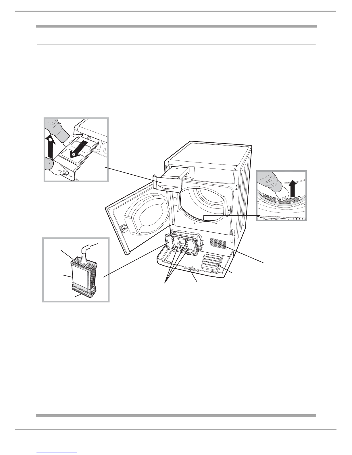
CONDENSER UNIT - CONDENSER DRYERS
For normal domestic use, the condenser should be cleaned once a month.
1. Open the condenser cover by pulling on the handle.
2. Rotate the 3 clips and pull the condenser towards you to remove. Some water is normal.
3. Flush the condenser unit from the rear to remove fluff deposits.
4. Refit the condenser, with the arrows pointing upwards. Once pushed home, rotate the 3 clips to
lock into place.
Open this flap by pulling the handle
Release the latches to remove the condenser
Remove and Rinse the Condenser
Refit the condenser the correct way up
over a sink or bath
Page 17

17 of 34
Indesit Company
Service Manual UK English
DRYER OVERVIEW
Introduction of Simplified Electronics
These Models are fitted with a new Electronic Module, which is fixed to a plastic carrier, located behind
the Console.
This Module replaces the Control Module (previously located in the Base), the Display Module +
Control Interface (previously located behind the Dashboard) and the Module to Display interface
harness, fitted to 2013 Production Tumble Dryers.
It is NOT interchangeable with earlier products which use 2 modules.
The module is covered with a white plastic water shield which must always be fitted correctly and
retained with its fixing clip.
Programming Connector
The module is programmed using Memwriter and a Hardware
Key or with a SmartCard Reader and Card, connected using a
Low End Adaptor.
(See pages 27 & 28 - Contol Board Programming)
These models have an Auto Test Cycle. See pages 7 & 8.
Fault Codes
These Models do NOT display a fault code if the dryer is in a
Fault Condition. See page 6.
Plastic Wate
r
Shield
Control
Module
Low End
Adaptor
Connection
point
Drum
Fluff
Barrier
(if fitted)
Low End Adaptor connector
Page 18

18 of 34
Service Manual UK
Indesit Company
English
DRYER OVERVIEW - CONDENSER MODELS
These Condenser Auto Tumble Dryers are freestanding with a round door on the front that can be
opened to allow the drum to be loaded with clothes.
The door is NOT reversible.
The facia moulding across the top of the front panel houses the dryer user controls and water
container.
Within the cabinet is a drum, which is capable of accepting a maximum 7 or 8 Kg* (depending on
model) load of damp clothing.
The drum is supported at the front by 4 plastic bearing pads or 1 drum support wheel and 2 bearing
pads (depending on model) mounted on the front air duct and a single bearing at the rear located in
the rear panel. A shaft fixed to the rear of the drum runs in the rear bearing.
The drum is driven by a belt, which p asses around it s pe riph ery an d on to the sh af t o f a moto r secured
to the base of the dryer. The belt is elasticated and tensioned by a pulley mounted to the motor.
As well as driving the drum the motor also drives impellers (rotors), fixed to each end of its shaft.
The front impeller draws cold air into the dryer, while the rear impeller recirculates drying air. The
addition of heat to the recirculating air is provided by a heating unit attached to the rear panel, enabling
the air to hold moisture when in contact with the wet load, thus causing it to dry.
As the warm recirculating air passes through the drum it collects lint as well as moisture. To prevent
the lint from blocking the heat exchanger (condenser), the air is passed through a filter located in the
front air duct door. The filter unit is positioned so as to be easily removable for cleaning by the user.
After passing through the filter, the circulating air is dusted through passageways in a heat exchanger
(condenser) located in a housing on the base of the dryer. Cold air is drawn into the dryer and flows
across the heat exchanger passageways. This cold air is not mixed with the warm damp recirculating
air , but is drawn into the dryer. This has the effect of reducing the circulat ing air temperature , causing it
to give up its moisture. (Cold air holds less moisture than hot air.) The now warm cooling air is
exhausted through the rear of the dryer.
The moisture removed from the recirculating air is pumped to a removable container mounted in the
left-hand side of the console. The user can easily withdraw the container to dispose of the collected
condense.
There is no requirement for venting to atmosphere on this dryer.
Cooling Air Circuit (open to atmosphere)
Recirculating Air Circuit (sealed)
CONDENSER DRYER
AIR FLOW
Page 19

19 of 34
Indesit Company
Service Manual UK English
Controls Overview
The user controls consist of a programme selection knob, option buttons and a Start/Pause button.
The control system consists of a user interface and control module, a thermistor mounted at the top of
the front air duct and one mounted on the heater assembly and a conductivity sensor.
The conductivity sensor is mounted in the front air
duct.
A single wire connects the sensor to the control
module.
The thermistors and conductivity sensor send values
back to the control module. The control module then
determines the programme duration and required
dryness of the load in a set of values for a particular
programme held within the control module software.
The combined Control and Power Module is a single
unit located at the top front right hand side of the dryer directly behind the console panel.
This module does not have a standard service port, and requires the use of a Low End Adaptor to
connect the Hardware Key to permit module programming.
The control module must be programmed with the relevant eeprom file if the control module is
replaced, the eeprom file becomes corrupted or if an updated file becomes available.
Programme Duration:
Once the programme has started the mo dule will determin e programme length for the si ze and type of
load. This detection is made within 10 minutes of the start of the progra mme and is achieved by use of
the front thermistor, rear thermistor and conductivity sensor. The module will then adjust the
programme time accordingly.
If the clothes are not sensed as dry when the 10 minute Cool Tumble period is reached, the module
does not start the Cool Tumble but continues to dry the clothes until the value from the conductivity
sensor indicates that the clothes are dry. The programme then advances into Cool Tumble.
Maximum Programme Period:
If after the maximum permitted programme time of 300 minutes (Note: this is an internal default value.)
the clothes are still not sensed as dry, the programme advances to Cool Tumble and completes the
programme. No fault is indicated if this occurs.
Heater Control
The control module also controls the heater. This has an upper and lower element. The lower (static)
element is permanently energised (except in cool tumble) and the upper element (dynamic) is cycled
on and off by the control module during a programme to maintain the correct temperature within the
drum for the programme selected.
If the user turns off the power or disconnects the mains cable or there is a power cut, the dryer will
remember its last settings and resume the programme when the start button is pressed.
If the event of a controls or thermistor failure, a cycling thermostat and one-shot thermostat are fitted
as safety devices.
Bearing Pads
Conductivity
Sensing Strip
Drum Support Wheels
Page 20

20 of 34
Service Manual UK
Indesit Company
English
FUNCTIONS DESCRIPTION
The Drying Guide allows you to consult a user friendly table of fabric types and load capacities.
The PROGRAMME knob sets the programme: rotate it until the indicator is pointing to the programme
you want to select. This will also power the dryer to the ON state. This replaces the On/Off button
found on previous models.
When either ’OFF’ (Hotpoint models) or the knob marker ’()’ (Indesit models), is positioned in the 12
o'clock position, it turns the machine Off and Cancels the Programme.
The OPTION buttons/lights select available options for your selected programme. The lights indicate
that the option has been selected.
The START/PAUSE button/light starts a selected programme. When you press this button there
will be one beep and the progress light s will flas h to confirm the acti on. When a programme is runn ing,
holding this button in pauses the programme and stops the dryer.
The light is green when programme is running, flashing amber if the programme has been paused or
flashing green if on stand-by waiting to start a programme.
Stand-by Mode
30 minutes after a programme has finished, if th e dryer is sti ll 'On' and no bu ttons have been tou ched,
the dryer will go into Stand-By mode. The LEDs and display will switch off. To reactivate and to remove
the dryer from Stand-By mode, turn the Programme Selector to position "1".
It will take a few seconds to recover from "Standby".
Another programme can be started or the dryer swit ched off by turning the selector to the OFF position.
The Progress or Delay lights show you the status of the programme, or the delay time when they
flash. During a delayed start the light s flash to show the delay selected. When (not flashing) they show
each stage of the programme by the corresponding light turning on.
The Empty Water indicator light signals that the water container should be emptied. The light will take
a few seconds to go out after replacing the empty water cont ainer, the dryer must be running for this to
happen. Note: If the water bottle fills the indicator light flashes, the heat is turned off and your clothes
will not dry.
The Clean Filter light gives you a reminder before every programme that it is essential to clean the
filter every time the dryer is used.
The Clean Condenser light gives you a reminder that it is essential to cle an the co nden ser at re gula r
intervals.
Page 21

21 of 34
Indesit Company
Service Manual UK English
USING THE DRYER
1. Load the Dryer with Laundry
2. Turn the Power On to the Dryer
3. Turn the Selector Knob to the required Programme - this will turn the Dryer On and select the
programme in one action.
4. Set any required options - if available
5. Push the Start/Pause Button to begin the programme.
Note:
Turning the programme knob to another programme after the cycle has started will NOT change
the cycle to the new programme. You must cancel it first.
Cancelling a Programme
To cancel a programme turn the selector knob to the OFF position and wait until it ends.
Then you can select another programme.
Automatic pre-post Crease Care
This is an automatic function which provides an anti-crease treatment both before and after the
drying programme.
By periodically rotating the drum before the start of the drying cycle, when a delayed start is
selected, the formation of creases is prevented.
On certain programmes the drum also rotates periodically at the end of the drying cycle.
The phase is stopped when the door is opened or when the knob is set to OFF.
Page 22

22 of 34
Service Manual UK
Indesit Company
English
OPTION BUTTONS
Note: Some buttons are disabled by software when their selection is not appropriate.
Start/Pause
This button is used to start every programme or to continue a programme if the door has been opened
and then closed, or if there has been a power interruption.
Pressing and holding in this button when a programme is running cancels the programme.
Low Heat
This Option can be set on Timed Cycles and some automatic Cycles.
If the Option if not available, when the button is pushed the LED will flash and a beep is heard.
When the Low Heat Option is enabled, the Target Heating Temperature is Reduced - therefore the
clothes will take longer to dry.
Alarm
When this Option is set the Buzzer Sounds at the end of the Drying Cycle to Signal that the
programme has ended and the garments are ready to wear.
Page 23

23 of 34
Indesit Company
Service Manual UK English
PROGRESS, ADVICE & WARNING LAMPS
Clean Filter / Empty Water Container LED
LED On -
Reminder to empty the water container and clean
the filter. The filter must be cleaned after every
use.
LED flashing and buzzer sounds -
The water container must be emptied immediately
and the dryer restarted. The flashing LED
indicates the container is full and the dryer will turn
the heater off.
After restarting, the LE D will take a few seconds to
go out.
Clean Condenser LED
The LED comes on every 20 cycles to remind the user that the condenser must be regularly cleaned.
The cycling on of the clean condenser LED is only controlled by the control module and is displayed as
a reminder. This dryer does not sense the state of the condenser.
Progress Lamps
During Drying Cycle:
Drying Denotes the dryer is drying the clothes
Cool Tumble Denotes the dryer is on the Cool Down period
End Denotes the cycle has finished.
Page 24

24 of 34
Service Manual UK
Indesit Company
English
COMPONENTS
Door
The door is constructed of several components, the outer
shell being powder coated metal.
And an inner lining consists of a moulding that clips into
position on the outer door shell.
The hinges are reversible, the extra holes on the opposite
side of the front panel being filled with blanking plugs. The
blanks need removal before changing the hing e side that
can be completed by diagonally transposing the hinges.
Filter
Comprises of a plastic mesh moulded into its housing,
which slides into the front air duct.
Door Switch
Normally open single pole microswitch activated by the
door on closure. This is the first switch in the electrical
circuit and therefore its rating, corresponds to the full loading of the product.
Control Module
This is an Electronic Device that monitors and controls all devices within the tumble dryer.
A production module is pre programmed at the factory with the relevant programmed file.
Service Modules are supplied non programmed and it is ne ce ssa ry for the Modul e to be prog ra mme d
by the Service Engineer. See pages 27 - 28 for Module programming.
Drum
The drum comprises of a zinc coated front and rear body and two
removable plastic lifters. The rear of the drum is perforated to allow
the passage of air. Fixed to the rear pressing is a support shaft which
runs in a bearing located in the rear panel of the dryer.
A drive pin and collar on the drum shaft prevents forward thrust
during use. The front lock seam of the drum rotates on front drum
support wheels.
Rear Thermistor
Fitted to the heater assembly above the heater.
Used by the electronics for controlling the temperature into the rear of the dryer.
Front Thermistor
Fitted to the bottom of the front air duct moulding, used by the electronics for controlling the
temperature.
One-Shot (Safety) Thermostat (White Spot)
The drum has a patterned finish to allow
for better air circulation within the drum.
Curved Drum paddles give extra garment
care.
Water
container
Condenser
cover handle
(pull to open)
Filter
Air intake
grille
Model &
Serial
Numbers
Rating plate
Patterned drum from a model fitted
with a stainless steel drum
Page 25

25 of 34
Indesit Company
Service Manual UK English
This device is a disc type thermostat set to operate at 143°C.
It is used as a Safety Device.
It is positioned above the element. If this device fails it cannot
be reset.
Cycling Thermostat ( 120°C +/- 3°C )
The cycling thermostat is mounted adjacent to the one-shot (safety) and is designed to open at 120°C. It
limits the temperature of the heat entering the drum.
Heater Unit ( for Condenser models = 2.3 kW )
Consists of coils wound on 'mica' supports, which are supported by ‘mica’ end insulators.
These end insulators fit into a steel pressing that also locates the rear thermal controls. This is fixed by
screws to the rear cover. This pressing also forms air guides. The heater elements thermal controls,
thermistors and rear cover are supplied as an assembly and has a 5 - way and a 2 - Way connector
provided to interface with the electronic module.
The heater has upper and lower heater sections.
The lower (static) heater is permanently energised and the upper heater (dynamic) is cycled on and off
by the control module during a programme to maintain the correct temperature for the programme
selected. See page 12 for Heater Technical information.
Motor
A two pole P.S.C running at 2800 rpm with the impeller fitted to the rear end of the shaft and the drive
belt running directly in grooves in the front end of the shaft. It is protected from overload by a
self-resetting internal cut-out that interrupts the electrical supply to the windings.
It is used together with a capacitor that is mounted on the base of the dryer.
Pump & Float Switch
Mounted on the bottom right-hand side of the rear panel, condensate water from the condenser
chamber is pumped via an external hose to the water container situated behind the console.
Operation of the Float Switch (water container full)
When the water container becomes full, the excess water is diverted back into the pump reservoir, which
causes the float to rise and the operation of the micro switch signals the module, the container is full.
After 2 minutes the machine will stop with the Start/Pause LED Flashing and the Empty Water LED
illuminated.
Drum Rear Seal
This unit comprises of a ring of foam with a webbing bearing face. Lubrication is applied to the drum where
the webbing surface runs, to reduce noise and wear. The seal reduces air losses at the rear of the drum.
The joints in the foam are sealed with glue and the joints in the webbing are stitched to further reduce air
leakage.
Drum Earthing
Drum Earthing is obtained by the teardrop bearing fixing
screw.
NOTE: - It is important that the correct screw is always
used to secure the teardrop bearing.
Teardrop bearing
Earth Screw
Page 26

26 of 34
Service Manual UK
Indesit Company
English
PROGRAMMES
Programmes
Standard Cotton:
Dries your items to a dryness level that allows you to put your clothes away straight from the dryer.
Cotton Extra Dry:
Dries your items to the maximum possible dryness level. Even drier than Standard Cotton dry.
Synthetics
Recommended to delicately dry synthetic fabrics.
Delicates
This program can also used for delicates/acrylic fabrics (2 Kg).
Jeans
It can also be used on other garments made from the same material, such as jackets.
Loads dried using this programme are usually ready to wear, the edges or seams may be slightly
damp. If this is the case, try turning the jeans inside out and running the programme again for a short
period.
Note: We do not recommend that you use this programme if your jeans have elastic waist bands,
studs or embroidery.
Refresh
A short programme suitable for refreshing fibres and garments. It lasts about 20 minutes.
Note: As this is not a drying programme, it is not to be used for garments that are still wet.
Programme
Max. load
(kg)
Compatible options
Cycle
duration*
1 Standard Cotton
Max Alarm - Low Heat.
140'
2 Cotton Extra Dry
Max Alarm.
150'
3 Synthetics
4 Alarm.
100'
4 Delicates
2 Alarm.
130’
5 Jeans
3 Alarm.
90’
6 Refresh
- Alarm.
20’
Timed drying cycle
30’ 60’ 80’100’120’140’160’180’ 200’
- Alarm - Low Heat.
-
* note: The duration of these programs will depend on the size of the load, types of textiles, the spin speed used in your washer
and any extra options selected.
Page 27

27 of 34
Indesit Company
Service Manual UK English
CONTROL BOARD PROGRAMMING for Modules with fixed EEProm
NOTE: This board does NOT have a physically replaceable EEProm.
Programming a Main Board
There are a number of ways the board can be pr ogrammed - some of which are not applicable to certain
markets.
Types of programming:
1. Handheld Terminal (Not UK)
2. Emit / Memwriter (UK - Indesit / Hotpoint Service Engineers)
3. Smart Reader & Smart Card (certain areas of UK market) see photo below and following page.
PROGRAMMING (Using EMIT)
This dryer can be programmed via the Emit PC, using a USB le ad (Part No. C00289046), Hardware key
(Part No. C00289048) and the Memwriter software.
Smart
Smart Card
this card holds
the program file
and can ONLY
be used ONCE.
Card
After the module
has been programmed
the card is automatically
erased.
Reader
USB Hardware Key and USB Cable
Connector pins are NOT replaceable
A
A = USB connector
B = not used
A
B
Part No. C00289046
Part No. C00289048
Page 28

28 of 34
Service Manual UK
Indesit Company
English
Connection to the Module
The Smartcard Reader or Hardware Ke y (shown below) MUST only be co nnected to the mo dule using
a Low End Adaptor - See method below. The Low End Adaptor edge connector plug connects to CN1
on the Module. The plastic Water Shield must be secured correctly after programming.
PROGRAMMING (Using Smartcard Reader / Card)
If the Module has been replaced during a repair the board will require programming using the following
method. A module which is not programmed will not function.
1. Do NOT connect the dryer to electrical supply at this point.
2. Insert the pre-programmed card into the Card reader. Care must be taken at this point to ensure the
card is inserted correctly with the Chip on the card facing the PCB of the Reader.
3. Insert the Reader and Card into module connection port located at the front of the dryer - see photo.
4. Connect the dryer to the Electrical supply;
Observe the electronic component side of the SmartCard Reader.
The LEDs on the Smart Card Reader will light in this sequence:
a. Red ON: Good Communication between Smart Card Reader & Card. See also Note 1 below.
b. Red OFF; Green Blinking: Download taking place.
c. At end,
Green ON = Download OK, module programmed, Red ON = Download NOT OK -see Note 1.
below.
6. Disconnect the appliance from the electricity supply.
7. Remove the Smart Card Reader.
8. Connect the appliance to the Electrical supply.
Note 1.
a If the Red LED is flashing SLOWLY, a card is inserted but either the card is blank (previously
used), is incorrectly inserted or there is a poor connection between the card and card reader.
b If the Red LED is flashing RAPIDLY, a card is NOT inserted or not inserted fully.
Note 2. SmartCard Re-Use
The Smart Card cannot be used again. It is erased after a su ccessful download of the settings file onto
the module.
Connection CN1
Hardware Key
Low End Adaptor
and USB cable
Plastic Water Shield
or Smartcard
Reader
Page 29

29 of 34
Indesit Company
Service Manual UK English
DISMANTLING INSTRUCTIONS - CONDENSER MODELS
SAFETY NOTES
1. ENSURE THAT THE APPLIANCE IS UNPLUGGED BEFORE DISMANTLING.
2. BEWARE OF SHARP EDGES ON METAL PANELS AND PRESSED PARTS.
A. Top Cover
1. Remove the 2 screws securing the top cover to the back panel.
2. Slide the top cover back and lift clear of the retainers.
B. Side Panels
1. Remove the top cover.
2. Remove the 3 screws securing the side panel to the rear panel.
3. Pull the side panel backward to disengage from the lugs on the base panel.
NOTE:- Different length screws are used to secure the side panels.
Take note of the screw length and positions when removing the side panels.
C. Console Panel
1. Remove the water container.
2. Remove the top cover as in (A).
3. Remove left side panel as in (B).
7. Carefully remove the plastic securing rivet which retains the plastic water shield.
8. Release the lower console securing lugs.
9. Noting the harness connections, disconnect the module.
10. Pull the console clear of the front Panel.
11. When reassembling, the Plastic Water Shield MUST be refitted and secured with the plastic rivet.
4. Remove the 2 screws on the left hand side of
console securing the water container housing to
the console.
5. Remove the 1 screw fixing the Water Container to
the front panel from the rear of the console (see
Fig. A).
6. Remove the 2 round headed screws securing the
console to each side panel along its top edge.
Screw revealed
after removing
the side panel
Water Shield
Plastic Rivet
Page 30

30 of 34
Service Manual UK
Indesit Company
English
D. Interface and Control Module Assembly
1. Remove the top cover as in (A).
2. Remove the console as in (C).
3. Remove the screws securing the Module to
the Console
4. Remove the programme knob by
compressing the tabs - see photo.
E. Belt
1. Remove the side panels as in (B).
2. Remove the cooling impeller cover using a small blade screwdriver to lift the cover locking tabs.
3. Remove the cooling impeller.
4. Remove the rear bearing as in (J).
5. Remove the heater unit as in (L).
6. Remove the recirculating impeller.
7. Remove the 3 hex head screws behind the recirculating impeller securing the motor to rear of the
base moulding. This will release tension on the belt.
8. Rotate the motor towards the centre of the dryer to disengage the belt from the jockey pulley.
9. Remove the 2 screws securing the rear panel to the side strut.
10. Remove the 2 screws securing the water container housing to the rear panel.
11. Remove the hose spigot from the container housing by rotating 90°.
12. Pull the rear panel backward to disengage the drum shaft from the dr um rear panel and slide the
belt back to remove from the drum.
13. Replace in reverse order. When refitting the belt first position the belt over the jockey wheel, refit
as in (N).
F. Front Panel, Door Seal & Front Thermistor
1. Remove the top cover as in (A).
2. Remove the console as in (C).
3. Remove the plinth.
4. Remove the 2 screws securing the front panel to the side strut.
5. Remove the 6 screws securing the front panel to the air duct.
6. Remove the 3 screws located behind the plinth securing the front panel to the base.
7. The front panel can now removed leaving the air duct in position.
G. Air Duct
1. Remove the front panel as in F).
2. Remove the belt as in (E).
3. Lift the air duct upwards to remove from the base.
Compress programme knob retaining tabs
Page 31

31 of 34
Indesit Company
Service Manual UK English
H. Front Bearing Pads / Support Wheels
Note: Either may be fitted - depending on production variations.
Ha Bearing Support Pads
1. Remove the drum as in (O).
2. Unclip the bearing pads which are located
on the front air duct.
Hb Drum Support Wheels
1. Remove the Drum (O).
2. Unscrew the Bearing Support Wheel fixing bolt.
Note:
When first started, it is normal for the drum to make
a noise for approximately 2 minutes, while th e drum
support wheels centralise to the load conditions.
I. Door Switch
1. Remove the top cover as in (A).
2. Remove the console as in (C).
3. Depress the locking tab securing the switch to the front panel and remove the switch.
J. Rear Bearing (Tear Drop shaped)
1. Remove the rear bearing cover.
2. Remove the drive pin and collar.
3. Remove the tear drop bearing fixing screw.
4. Slide the bearing off the drum shaft.
Bearing Support Pads
Support
wheel
fixing bolt
Teardrop Bearing
fixing Screw
Page 32

32 of 34
Service Manual UK
Indesit Company
English
K. Pump & Float Switch
1. Depress the 2 pump cover locating tabs and pull the cover clear (Photos 1 and 2).
2. Access can now be gained
to the pump and float
switch.
3. To remove the pump float
switch assembly, release
the 2 clips either side of the
assembly and lift clear
(Photo 3).
L. Heating Assembly, Thermostats & Thermistor
1. Remove the right hand side panel.
2. Disconnect the wiring to the heater multi-pin connector.
3. Remove the 8 screws securing the heater unit to the rear panel.
4. Remove the 2 screws securing the heater to the rear cover.
NOTE 1: If replacing the thermostats both the cycling and one-shot
thermostat MUST
be replaced should either fail.
NOTE 2: A cable tie must be used to secure the 3 way plug into
the heater connector - refer to photo.
NOTE 3: When refitting the heater cover, ensure the heater wiring
is not trapped between the inner and outer rear panels.
NOTE 4: 2 different screws are used to fit the heater cover.
The longer screws are to secure the heater cover to the base assembly.
Photo 1 Photo 2
Released Clips
Photo 3
Shown with
cover
removed
Cable Tie
Page 33

33 of 34
Indesit Company
Service Manual UK English
M. Motor
1. Slacken the belt as in (E) 1 to 8.
2. Lift the motor clear from the base moulding.
3. Replace in reverse order first positioning the belt over the jockey wheel.
It will be necessary to use the motor special tool as a lever on the motor casing (as illustrated) to
enable it to be rotated under tension to line up the holes in rear moulding with the fixing holes on
the motor casing.
Refit the 3 hex head screws.
N. Drum Assembly
1. Remove the top cover as in (A).
2. Remove the side panels as in (B).
3. Remove the console as in (C).
4. Slacken the belt as in (E) 1 to 8.
5. Remove the rear bearing as in (J).
6. Remove the front panel as in (F) leaving the air duct attached to the front panel if required.
7. The drum can now be removed from the rear panel.
8. Replace in reverse order.
NOTE: When reassembling, a new drive pin must be fitted.
O. Rear Seal
1. Remove the drum as in (N).
2. Remove the rear seal and clean any remnants of the seal and adhesive from the inner face of rear
panel.
IMPORTANT NOTE
The correct size Drum Rear Seal must be always be fitted to the Dryer.
Refer to the parts system for correct part number.
Rotate motor with the motor special
tool using downward pressure to
tension the belt and line up motor
fixings in rear moulding
Note: It is recommended the motor
If Pipe Grips or a similar tool is used,
ensure the pliers do not cause damage
to the motor windings.
Special Tool is used to fit the motor/belt.
Page 34

34 of 34
Service Manual UK
Indesit Company
English
END
Indesit Company UK Ltd.
2015
 Loading...