

Page 1
B
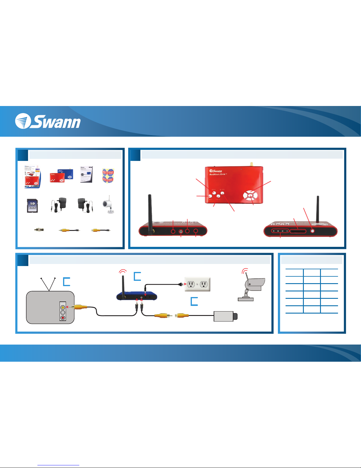
Getting to Know Your DVR
Wireless Camera
Channel Indicators
SD Card Slot
On/Off
Switch
*CH1 - 2414MHz, CH2 - 2432MHz
CH3 - 2450MHz, CH4 - 2468MHz
Camera
Input
Video
Output
to TV
Power
Input
Mode Button
- switch between live and
playback modes
Snap Button
- take a photo snapshot or
start a 10s video recording
OK Button
- confirm or choose
selection
Display Button
- change cameras and
turn PIP on/off
Menu Button
- enter/exit menu or
return to previous
Directional Arrows
- highlight options or change selections
- UP Arrow toggles Motion on/off
- Down Arrow toggles Photo or Video modes
Wireless Camera Selector
- push to change wireless channel
- change between 1 - 4 wireless cameras
- operates in 2.4GHz range*
Package Contents
A
Red or Blue
Alert DVR
Packaging
Security
Stickers
Quick Start
Guide
DVR Power
Supply
Male Video Output
Cable to TV
Female Video Input
Cable for Camera
SD Card
(Optional)
Female BNC
to Male RCA
Camera Power
Supply
Wireless
Camera
RedAlert / BlueAlert DVR Easy Setup Guide
www.swannsecurity.com
Swann Communications • Toll Free Technical Support: USA - 1-800-627-2799, 1-877-274-3695, Australia - 1300 13 8324 • Email: tech@swann.com.au
Monitor and Camera Connections Memory Usage Chart
C
1
2
3
Back of TV
INPUT
Back of DVR
*INPUT may be labelled as A/V, Source, L1, L2, channel 0 etc. Consult TV manual/manufacturer for more information
Connect the AV cable
to back of TV and tune
TV to correct INPUT*
Connect the Power Cable
to the back of the unit and
an available power outlet
Connect your wired
camera to input or turn on
your wireless camera
Note: the above chart is for reference only -
the number of images and videos are
approximate and may vary based on image
complexity and amount of motion captured
Wireless
Camera
SD Card Size
128MB 2000 250
256MB
512MB
1GB
2GB
4000
8000
16000
32000
500
1000
2000
4000
JPEG Images AVI Videos
Wired Camera
Page 2
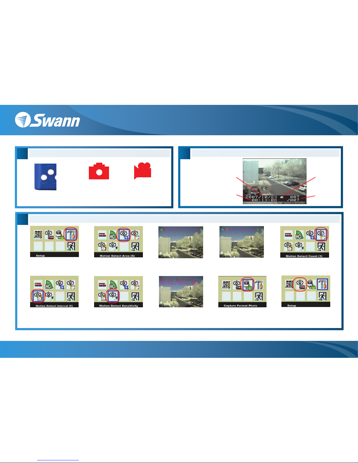
E
Viewing Recorded Images
6. Highlight Motion Detect Interval and
press OK to choose 1, 3 or 5. The
number indicates the pause in seconds
between two instances of motion detection
Time image
recorded
Date image
recorded
Press the MODE
button to enter
playback mode
Use the LEFT and
RIGHT arrows to
change images
Image number
Type of capture
photo or video
Motion Detection Recording Setup
F
Manual Recording
1. In the menu highlight Setup
and press the OK button
Push the SNAP button
to record an image or
start a video recording
The Video mode will
will take approximately
10 seconds of video
The Camera mode will
take a still image
HINT: The Down arrow toggles between camera/video
mode when viewing your cameras
9. Finally, back in the main menu
change Capture Format to Photo
or AVI. Note the Interval and Count
options apply only to photo detection
2. Choose Motion Detect Area
and press the OK button
10. To activate motion detection, set
Motion Detect to ON in the menu
or when viewing your camera push
the UP arrow to toggle motion on/off
7. Next highlight Motion Detect
Sensitivity and press the OK
button
8. Within the rectangle is where
motion will be detected. The
lower the Target Value the
easier to sense/begin recording
3. Use the Left and Right arrows
to change the size of area to
detect and press the OK button
4. Next use the arrows to move the
rectangle to a region you want to
detect and hit the OK button
5. Hightlight Motion Detect Count and
press OK to change between 1, 3 or 5.
The number indicates how many
images will be captured per detection
D
RedAlert / BlueAlert DVR Easy Setup Guide
www.swannsecurity.com
Swann Communications • Toll Free Technical Support: USA - 1-800-627-2799, 1-877-274-3695, Australia - 1300 13 8324 • Email: tech@swann.com.au
 Loading...