

Page 1
Swann Communications warrants this product against defects in workmanship and material for a period
of one (1) year from its original purchase date. You must present your receipt as proof of purchase for
warranty validation. Any unit which proves defective during the stated period will be repaired without
charge for parts or labour or replaced at the sole discretion of Swann. The end user is responsible for
all freight charges incurred to send the product to Swann’s repair centres. The end user is responsible
for all shipping costs incurred when shipping from and to any country other than the country of origin.
The warranty does not cover any incidental, accidental or consequential damages arising from the use
of or the inability to use this product. Any costs associated with the fitting or removal of this product
by a tradesman or other person or any other costs associated with its use are the responsibility of the
end user. This warranty applies to the original purchaser of the product only and is not transferable to
any third party. Unauthorized end user or third party modifications to any component will render all
warranties void. By law some countries do not allow limitations on certain exclusions in this warranty.
Where applicable by local laws, regulations and legal rights will take precedence.
This equipment has been tested and found to comply with the limits for Class B digital device, pursuant
to part 15 of the FCC Rules. These limits are designed to provide reasonable protection against
harmful interference in a residential installation. This equipment generates, uses and can radiate radio
frequency energy and, if not installed and used in accordance with the instructions, may cause harmful
interference to radio communications. However, there is no guarantee that interference will not occur
in a particular installation. If this equipment does cause harmful interference to radio or television
reception, which can be determined by turning the equipment off and on, the user is encouraged to try
to correct the interference by one of the following measures:
• Reorient or relocate the receiving antenna
• Increase the separation between the equipment and the receiver
• Connect the equipment into an outlet on a circuit different from that to which the receiver is
connected
• Consult the dealer or an experienced radio/TV technician for help
These devices comply with part 15 of the FCC Rules. Operation is subject to the following two conditions:
1. These devices may not cause harmful interference.
2. These devices must accept any interference received, including interference that may cause
undesired operation.
Professional HD
Security Camera
5MP HD Dome Camera
EN
INSTRUCTION MANUAL
Security Made Smarter
Important Note: All jurisdictions have specific laws and regulations relating to the use of cameras.
Before using any camera for any purpose, it is the buyer’s responsibility to be aware of all applicable
laws and regulations that prohibit or limit the use of cameras and to comply with the applicable laws
and regulations.
WARNING: MODIFICATIONS NOT APPROVED BY THE PARTY RESPONSIBLE FOR COMPLIANCE COULD
VOID USER’S AUTHORITY TO OPERATE THE EQUIPMENT.
Helpdesk/Technical Support
5 Limited Warranty - Terms & Conditions 6 FCC Verification
tech@swann.com
support.swann.com
USA 1800 627 2799
USA Parts & Warranty
1800 627 2799
(M-F, 9am-5pm US PT)
Australia 1800 788 210
New Zealand 0800 479 266
UK 0808 168 9031
MT891CAMVER1E
© Swann Communications 2017
Page 2
Congratulations on your purchase of the Swann 5MP Professional HD Security Camera.
You’ve made a fine choice for keeping a watchful eye over your home or business. The
camera delivers brilliant and amazingly clear high definition images and videos in both day
and nighttime conditions even in complete darkness. The camera also features an OSD
(On-Screen Display) that you can access to change ad vanced image settings usin g the
PTZ control inter face on your DVR.
DVR Compatibility
The camera is compati ble with the following Sw ann 5MP DVR models:
• DVR-4900 Series DVRs
Other models may be ad ded to this list - since the time of publi cation we will have
released newer DV Rs with which the camer a may be supported, check th e compatibility
list on our website for more information.
Important Safety Instructions
1. Make sure the camera is fixed correctly and stable if fastened in place.
2. Do not operate if wires and terminals are exposed.
5
VIDEO IN
1627384
IN
OUT
AUDIO
VGA LAN
D+D-
RS-485
12V12V
POWER
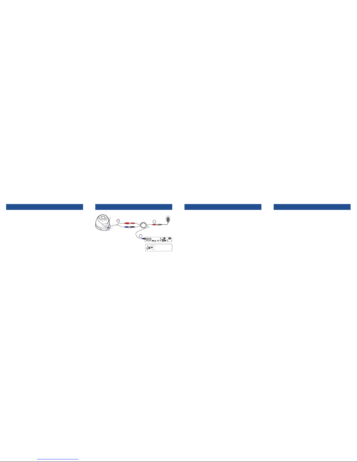
Follow the example diagram below to connect the camera to your DVR.
Extension
cable
Digital Video Recorder
Power
Power adapter
Video
Tip: Twist to lock
video connectors
1. Connect the camera’s Power and Video cable
to the extension cable’s DC and BNC plugs.
2. Connect the other end of the BNC extension
cable to a video input channel on your DVR.
3. Connect the other end of the DC extension
cable to the power adapter and then plug the
power adapter into a wall outlet. (For multipack cameras, use the power splitter cable
included with the power adapter.)
Note: Images contained in this diagram
are for illustrative purposes only.
1
2
3
2 Connecting the camera1 Welcome 3 Mounting the camera 4 On-Screen Display (OSD)
Tip: Run cables inside a wall cavity or other protected
enclosure, avoid bending at sharp angles, and ensure that all
wiring and the connectors are suitably insulated and protected
from moisture and sunlight.
The camera can be mounted onto a flat, vertical or horizontal surface and must have
sufficient strength to hold the camera. Materials such as hardwood, brick or masonry are
good options.
1. Loosen the plate screw located at the dome base using a hand screwdriver (Phillips
head) then carefully remove the enclosure and dome.
2. Position the dome base in the location you want to mount it then mark the screw holes
on the surface to position the screws.
3. Using the appropriate screws for the surface you are mounting to, screw the dome
base into place. If you’re mounting to a wooden surface, screw the camera directly
to the surface. If mounting to a masonry surface, you’ll need to use the included wall
plugs.
4. Replace the enclosure and dome.
Aiming the camera
5. The dome can be rotated left or right and aimed in almost any direction from wherever
you choose to mount it. It can help to move a monitor out to the camera’s location to
ensure you get it aimed and positioned properly.
6. After you’ve finished adjusting the viewing angle, make sure the plate is clipped onto
the underside of the enclosure, then carefully press down the encloseure and tighten
(don’t overtighten) the plate screw to secure the dome in its position.
plate screw
dome base
enclosure
The camera has an OSD (on-screen display) that is accessable using the DVR’s PTZ
control interface. For details on setting up your DVR to operate the camera’s OSD, see
the Pro-T890 & T891 OSD Guide which can be downloaded from the Swann Tech Support
website at:
http://support.swann.com
What is the OSD?
The OSD allows you to adjust the appearance and characteristics of the image shown on
the camera. It is an optional, advanced feature and recommended only for experienced
users. There’s no requirement to use the OSD - in the majority of situations, the automatic
settings work quite well.
The following is an some of the options available on the camera’s OSD menu. For a more
detailed guide to the OSD functionality, download the Pro-T890 & T891 OSD Guide.
• Exposure: Adjust exposure settings according to the existing light conditions.
• WB (White Balance): Choose from a selection of white balance options to adjust screen
color and obtain the most accurate reproduction of color tone in the scene.
• Day-Night: Control the camera’s colour mode during different times of the day and night
• Video Setting: General image settings common to most cameras.
 Loading...