

Page 1
ONSCREEN DISPLAY
(OSD) GUIDE
FOR PRO-T890 HD CAMERA
EN
Page 2

2
CONTENTS
CONTENTS ..................................................................................................... 2
INTRODUCTION .............................................................................................3
OPERATING THE OSD ....................................................................................4
MAIN MENU ...................................................................................................5
OUTPUT MODE ............................................................................................... 7
EXPOSURE ..................................................................................................... 8
SPECIAL ........................................................................................................9
SPECIAL DPC ..............................................................................................10
ADJUST ..........................................................................................................11
Page 3
3
The PRO-T890 camera uses a special in-line control method called ‘Coaxitron’ which sends
the control signals through the video signal cable, enabling you to access the camera’s OnScreen Display (OSD) directly via the PTZ interface on your DVR. The OSD allows you to control
the appearance and characteristics of the image shown on your camera. It features a myriad
of settings that can be adjusted to obtain the best possible image quality in any surveillance
environment, providing you the flexibility to install the camera in the most challenging of lighting
situations. If you are experienced in photography or video-making, then many of the camera’s
functions are things you’ll be familiar with.
Setting up the DVR
If you intend to use the OSD, you will first need to make sure your DVR is configured with the
correct PTZ protocol setting (the language the DVR uses to talk to the camera). Follow the steps
below carefully - the DVR may not display the OSD if the PTZ protocol setting is not configured
properly!
1. Make sure the camera is connected to the DVR.
2. From the DVR, go to the PTZ menu screen (for example, Menu > Camera Management >
PTZ. If unsure, refer to the DVR documentation for information on how to access this menu).
3. Select the camera you want to configure from the Camera drop-down list.
4. Click PTZ Parameter Settings.
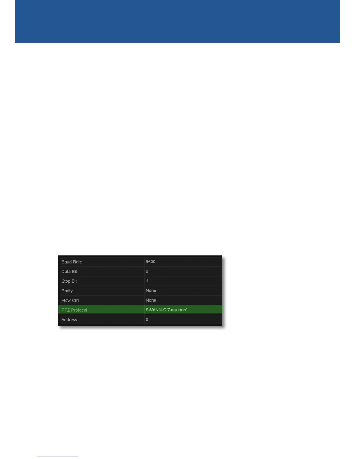
This displays the PTZ Parameter Settings screen.
5. Select “SWANN-C(Coaxitron)” from the PTZ Protocol drop-down list as shown below.
6. Click OK to save the settings. Repeat steps 3-6 for each PRO-T890 camera that you have
connected.
INTRODUCTION
Page 4
4
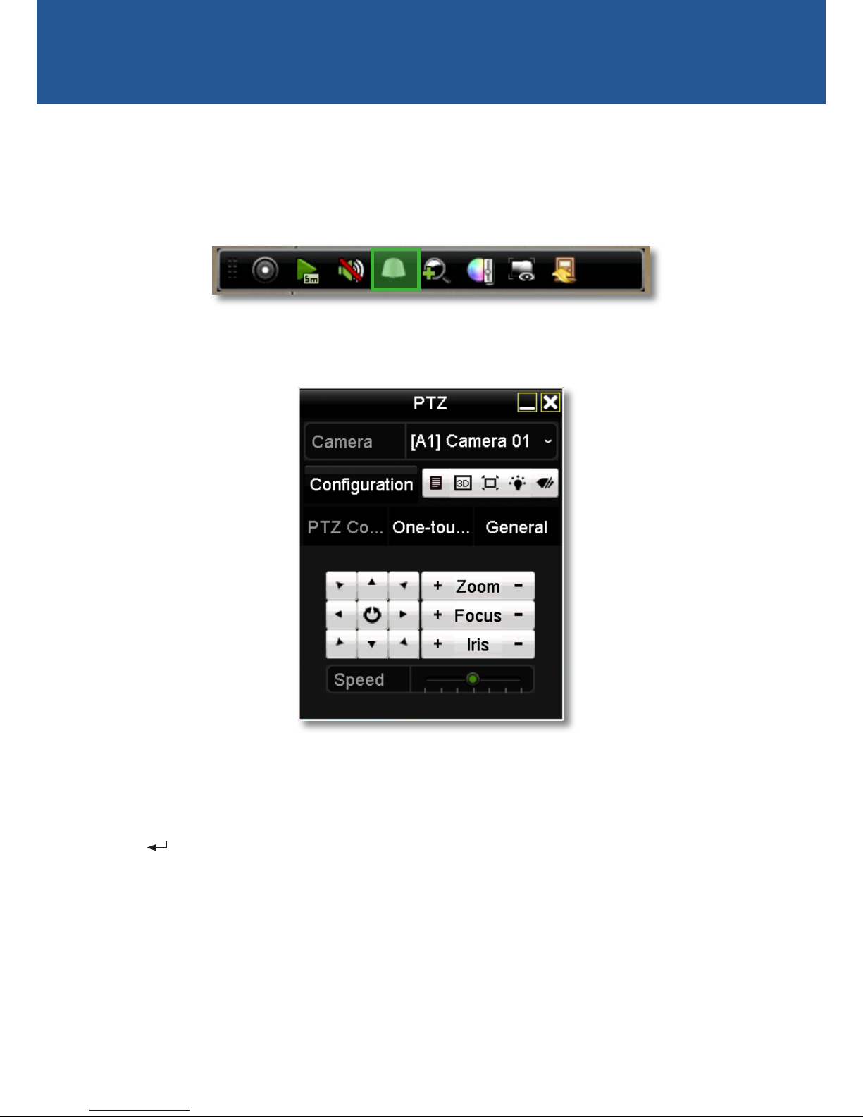
The PRO-T890 camera’s OSD is displayed and operated using the PTZ control panel on your DVR.
You can access the PTZ control panel directly from the Live View screen by selecting the channel
screen of the corresponding camera which displays the camera toolbar and then clicking the PTZ
icon as shown below.
• To display the camera OSD menu on the screen, click the Iris + button.
• To navigate through the menu, click the up or down arrow.
• To change settings for a menu item, click the left or right arrow.
• The symbol indicates that there is a submenu for the menu item or that the setting for a
particular menu option can be immediately saved and applied on the camera (without need
going back to the main menu and selecting EXIT > SAVE & END. Simply click the Iris + button
to perform either function. The camera will automatically reboot to apply the new setting.
• To return to the previous menu from a submenu, select “Return” and click the IRIS + button.
• The Zoom, Focus and Speed functions, and other function buttons on the PTZ control panel
not described here have no effect on the OSD.
OPERATING THE OSD
Using the PTZ Control Panel
Camera toolbar
Page 5

5
MAIN MENU
Output Mode: See page 7 for information.
Exposure: See page 8 for information.
Backlight: Lets you optimise and obtain an even exposure across the scene where there is
bright light sources in the background with one of the following modes.
• BLC: Back Light Compensation. Use this function to correct exposure for an area which
appear dimmer in the foreground due to strong natural light in the background (e.g., a bright
window). You can configure the BLC level and the position and size of the BLC area.
• HLC: High Light Compensation. Use this function to mask extremely bright areas or sources
(e.g., a bright window during the day or car headlights at night) in the scene and improve
overall image clarity. You can configure the HLC level and the position and size of the HLC
mask.
White Balance: In the default setting (ATW), the camera will attempt to create as neutral a white
balance as possible. Colours tend to be slightly underexposed, but represented quite accurately.
The colour of the light will have less of an effect on how the camera perceives colour. You can
also select one of the following settings:
• AWC➙SET↵: With this you can find the optimal luminance level for the current environment.
You’ll need to focus the camera on a white surface (or a large, white object), then click the
“Iris +” button.
• Manual: Define a custom white balance by adjusting the Blue and Red levels manually.
Day & Night: In the default setting (AUTO), the camera will alternate automatically between
colour during the day or under artificial lights, and switch to black and white in low light
conditions or when the active infrared night vision is active. You can also select one of the
following settings:
• COLOR: The camera will only operate in day mode. The IR filter will stay activated and the
camera will not be able to use IR light either from the camera itself or from other sources.
MAIN MENU
1. OUTPUT MODE
2. EXPOSURE
3. BACKLIGHT
4. WHITE BAL
AUTO
ATW
OFF
5. DAY&NIGHT
6. SPECIAL
7. ADJUST
SAVE&END
8. EXIT
Page 6

6
MAIN MENU
MAIN MENU
1. OUTPUT MODE
2. EXPOSURE
3. BACKLIGHT
4. WHITE BAL
AUTO
ATW
OFF
5. DAY&NIGHT
6. SPECIAL
7. ADJUST
SAVE&END
8. EXIT
Only visible light will be detected by the camera.
• B/W: The camera will only operate in night mode. The camera will switch to black and
white display and the IR filter will be deactivated. In day time if the camera is outside, the
combination of visible and IR light from the sun may cause the image to be washed out.
Special: See page 9 for information.
Adjust: See page 11 for information.
Exit: Select one of the following -
• SAVE & END: Save the settings and exit the OSD menu.
• RESET: Restore all settings back to their factory default configuration. The camera will be
rebooted.
• NOT SAVE: Discard any changes made to the settings and exit the OSD menu.
Page 7

7
OUTPUT MODE
Resolution: The camera’s resolution is displayed.
Framerate: The maximum frame rate which the camera can support is displayed. Please note
the frame rate of any captured video is determined by the frame rate (fps) recording setting on
the DVR.
Video Out: Lets you set the camera to the appropriate video output standard. This should match
the electrical frequency of your environment, particularly if the camera is mounted indoors,
to eliminate any flickering caused by artificial light sources. For example, NTSC (used in USA,
Canada and Japan) or PAL (used in UK and Australia).
OUTPUT MODE
1. RESOLUTION
2. FRAMERATE
12.5P
5MEGA
3. VIDEO . OUT
RET
PAL
4. RETURN
Page 8

8
EXPOSURE
Shutter: Lets you control the behaviour of the camera shutter – how long the camera shutter
is open to expose light into the camera sensor. The longer the electronic shutter is “open”, the
more light it will let in. We recommend leaving this on AUTO. You can also manually adjust the
camera shutter speed. Options range from 1/25 to 1/50000. Generally, the slower the shutter
speed the brighter the picture. Faster shutter speeds tend to be used for capturing fast moving
objects to reduce motion blur.
Flicker Mod: If you find that the image is flickering because of different frequencies on
surrounding lighting, select ON to help reduce flickering.
AGC: Automatic Gain Control. Lets you adjust the video gain of the camera using the slider to
enhance image clarity in a poorly lit scene. A higher gain level will result in a brighter image at
the cost of lower image quality (i.e., grainy look to the image).
Brightness: Lets you adjust the brightness of the image using the slider.
D-WDR: Digital Wide Dynamic Range. The default setting is AUTO. You can also manually adjust
the gamma level to brighten objects in underexposed areas and improve the overall picture
quality of high contrast lighting scenes (e.g., where there is intense backlight such as bright
sunlight coming from windows or doors)
EXPOSURE
1. SHUTTER
2. FLICKER MOD
OFF
AUTO
---- ---- ---- |--- ----
3. AGC
4. BRIGHTNESS
AUTO
5. D–WDR
RET
6. RETURN
10
37
---- ---| ---- ---- ----
Page 9

9
SPECIAL
Mirror: Lets you change the orientation of the image to either horizontally reversed (H-FLIP),
upside down (V-FLIP) or horizontally reversed upside down (ROTATE). Using this function does
not affect the orientation of text on the screen.
DPC: Dead Pixel Compensation. Enables you to digitally correct any defective pixels present in
the image. See page 10 for more information.
Language: Lets you change the OSD menu language.
SPECIAL
1. MIRROR
2. DPC
OFF
3. LANGUAGE
RET
ENG
4. RETURN
Page 10

10
SPECIAL DPC
Live DPC: (Default - ON) Automatic real-time correction of white or black pixel defects.
• AGC LEVEL: Adjust the AGC level for the Live DPC.
• LEVEL: Adjust the sensitivity level of the Live DPC.
White DPC: Enable correction of white pixel defects.
• POS / SIZE: Configure the position and size of the White DPC zone. Use the arrow buttons on
the PTZ control panel to adjust the position of the zone then click the “Iris +” button to adjust
size.
• START: Begin the DPC test. The screen will flicker momentarily and correct any white pixel
defects within the zone.
• DPC VIEW: Show existing white pixel defects, if any, that have been corrected. The screen will
turn black.
• LEVEL: Adjust the sensivity of the White DPC function.
• AGC: Adjust the AGC level of the White DPC function.
Black DPC: Enable correction of black pixel defects.
• POS / SIZE: Adjust the position and size of the Black DPC zone. Use the arrow buttons on the
PTZ control panel to adjust the position of the zone then click the “Iris +” button to adjust the
size.
• START: Begin the DPC test. The screen will flicker momentarily and correct any black pixel
defects within the zone.
• DPC VIEW: Show existing black pixel defects, if any, that have been corrected. The screen will
turn white.
• LEVEL: Adjust the sensitivity of the Black DPC function.
• AGC: Adjust the AGC level of the Black DPC function.
DPC
1. LIVE DPC
2. WHITE DPC
ON
3. BLACK DPC
RET
OFF
OFF
4. RETURN
Page 11

11
ADJUST
Sharpness: The clarity of detail and edges in the image. When AUTO is selected, you can
configure the following values:
• LEVEL: Adjust the sharpness level. The higher the number, the more crisp objects will
appear in the image. The lower the number, the softer objects will appear in the image.
• START AGC: Set the level at which the camera will start using automatic gain control to
improve the image sharpness in low light conditions.
• END AGC: Set the level at which the sharpness adjustment in low light conditions using
automatic gain control will stop.
Monitor: Lets you adjust the image according to the monitor that you are using.
• GAMMA: Set the gamma level from 0.45 ~ 1.00.
• BLUE GAIN: Set the blue levels form 0 ~ 100.
• RED GAIN: Set the red levels form 0 ~ 100.
LSC: Lens Shading Compensation. Enable to brighten areas on the periphery of the image.
ADJUST
1. SHARPNESS
2. MONITOR
AUTO
3. LSC
RET
OFF
4. RETURN
Page 12

12
Security Made Smarter
© Swann Communications 2017
 Loading...