

Page 1
PRO-752 Dome
M752CAM020113E
English
Page 2

Warranty Information, Verifications & Warnings
Swann Communications warrants this product against defects in workmanship and material for a period
of one (1) year from its original purchase date. You must present your receipt as proof of date of purchase
for warranty validation. Any unit which proves defective during the stated period will be repaired without
charge for parts or labor or replaced at the sole discretion of Swann. The end user is responsible for all
freight charges incurred to send the product to Swann’s repair centers. The end user is responsible for all
shipping costs incurred when shipping from and to any country other than the country of origin.
The warranty does not cover any incidental, accidental or consequential damages arising from the use
of or the inability to use this product. Any costs associated with the fitting or removal of this product by
a tradesman or other person or any other costs associated with its use are the responsibility of the end
user. This warranty applies to the original purchaser of the product only and is not transferable to any
third party. Unauthorized end user or third party modifications to any component or evidence of misuse
or abuse of the device will render all warranties void.
By law some countries do not allow limitations on certain exclusions in this warranty. Where applicable
by local laws, regulations and legal rights will take precedence.
For Australia: Our goods come with guarantees which cannot be excluded under Australian Consumer
Law. You are entitled to a replacement or refund for a major failure and for compensation for any other
reasonably foreseeable loss or damage. You are also entitled to have the goods repaired or replaced if the
goods fail to be of acceptable quality and the failure does not amount to major failure.
Warning
Modifications not approved by the party responsible for compliance could
void user’s authority to operate the equipment.
IMPORTANT SAFETY INSTRUCTIONS
• Make sure product is fixed correctly and stable if fastened in place
• Do not operate if wires and terminals are exposed
IMPORTANT NOTE: All jurisdictions have specific laws and regulations relating to the use of cameras.
Before using any camera for any purpose, it is the buyer’s responsibility to be aware of all applicable laws
and regulations that prohibit or limit the use of cameras and to comply with the applicable laws and
regulations.
FCC Verification
NOTE: This equipment has been tested and found to comply with the limits for Class B digital device,
pursuant to part 15 of the FCC Rules. These limits are designed to provide reasonable protection against
harmful interference in a residential installation. This equipment generates, uses and can radiate radio
frequency energy and, if not installed and used in accordance with the instructions, may cause harmful
interference to radio or television reception, which can be determined by turning the equipment off and
on, the user is encouraged to try to correct the interference by one or more of the following measures:
• Reorient or relocate the receiving antenna
• Increase the separation between the equipment and the receiver
• Connect the equipment into an outlet on a circuit different from that to which the receiver is
connected
• Consult the dealer or an experienced radio/TV technician for help
These devices comply with part 15 of the FCC Rules. Operation is subject to the following two conditions:
• These devices may not cause harmful interference, and
• These devices must accept any interference received, including interference that may cause
undesired operation.
Page 3
Introduction
Congratulations on your purchase of this Swann PTZ Camera!
This installation and setup guide will walk you through the basics of connecting the
PTZ camera to your DVR, and walk you through the settings on the DVR you’ll need
to use to control the camera.
Be aware that the camera must be connected to a compatible DVR to operate
correctly.
The included stand-alone RS485 controller will operate the basic features of the
camera, and access the on-screen display (OSD). You won’t be able to program the
camera properly or integrate it’s functions with your system unless your DVR is
configured to do so.
Compatibility
This Swann PTZ camera is compatible with most current Swann DVRs. We can
confirm that it will work with the following DVR models:
1200, 1300, 2500, 2550, 2600, 3000 and 4000 series DVRs.
This is not an exhaustive list - since the time of publication we may have released
newer DVRs with which this camera is compatible. Check your DVR documentation
to learn more. Any Swann DVR with an RS485 port should be compatible with this
camera.
IMPORTANT: If mounting the camera outside, be sure to properly seal all joints in
the mounting arm/bracket using a silicon sealant. If this is not fully sealed, water
can enter the dome causing malfunction or failure.
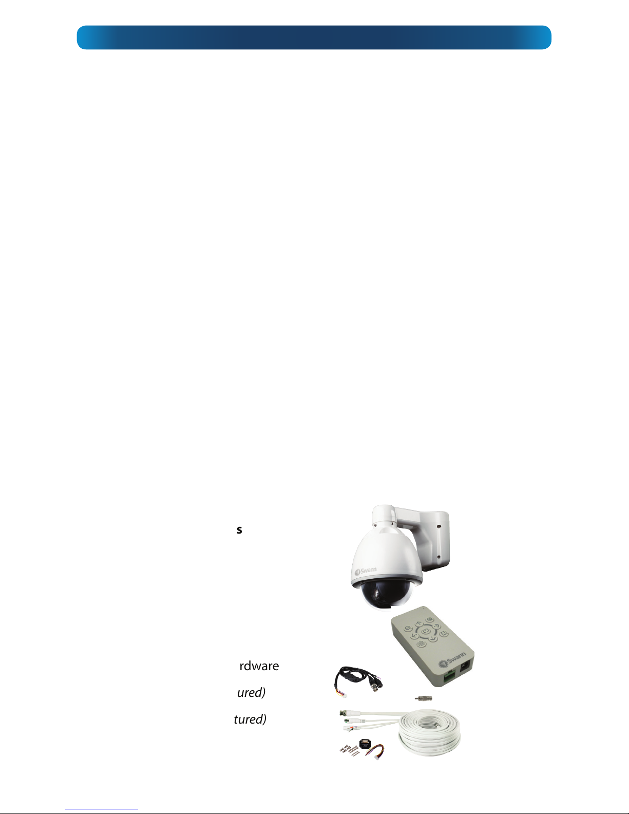
Package Contents
PRO-752 Camera
RS485 Controller
Camera Cable
Extension Cable
Screws and Mounting Hardware
Power Supply (not pictured)
Power Splitter (not pictured)
Page 4

Step 1. Connecting the Camera Cable
Before mounting the camera, it is important to connect it correctly.
1. Run the cable through the mounting arm or bracket
you would like to use.
2. Make sure you run the cable through starting with the
camera end (not the end with the BNC connectors they’re too big to fit).
3. Once the cable has been pulled through, plug it into
the top of the camera.
4. If you’re planning to mount the dome outside, cover
the screw threads with a silicon sealant before screwing
the unit together. Failing to do so will compromise the
waterproofing of the dome.
5. Then, screw the mounting arm/bracket onto the dome.
Be careful not to damage the connectors on the end of the cable or to the camera,
particularly when unplugging the camera, as the connectors are fragile!
Step 2. Connecting the RS485 Controller (if required)
You’ll only need to complete this step if you
want to change the command address of the
camera, of if you want to alter the camera’s
settings via the OSD.
1. Remove the RS485 plug from the back of
the RS485 controller.
2. Insert the grey/black wire into the -B side of
the RS485 plug, and screw into place.
3. Insert the purple/red wire into the +A side
of the RS485 plug, and screw into place.
4. Plug the RS485 plug into the RS485 port on
the back of the RS485 controller.
Note that the polarity of the RS485 controller may or may not be the same as the
polarity of the RS485 plug on the rear of your DVR. Double check against the diagram!
Step 3. Mounting the Camera
After connecting the camera, place it in the desired location. Then, using an
appropriate screw for the surface you’re fixing the dome to, screw the arm/bracket
into place.
Ensure you have enough cable coming through the mounting arm/bracket to
connect it to your system. If you want to run the cables through a wall/ceiling, be
sure to drill a hole for the cable as well.
Closeup of the RS485 controller connections
showing the RS485 (left) and the DC input (right)
Installation Guide
Page 5

Connecting the Camera
• For information on how to physically connect the camera, see the connection
diagram on page 7.
• If you’ve only got one PTZ device, you won’t have to configure the camera at all,
although you still can, if you choose to (see the online OSD guide available for
free download from www.swann.com/OSD).
• If you’ve got multiple PTZ devices, then you’ll need to assign the command
address of each to be unique.
What is this “OSD”?
The OSD is the On Screen Display, and it will allow you to customize and control many
aspects of the camera’s operation which are, by default, controlled automatically.
There’s no requirement to use the OSD - in the majority of situations, the automatic
settings work quite well.
As we’re continually improving and updating our software and hardware, we offer
an online guide for the OSD functions of these cameras. To get a copy of the latest
documentation, log onto www.swann.com/OSD
To assign the command address of the PRO-752:
• Connect the white RS485 controller to the RS485 pins on the camera cable.
• Press the middle button on the RS485 controller to bring up the on-screen menu.
• Using the up and down arrow buttons to choose an option and the middle
button to select/confirm a choice, navigate to Protocol Setup.
• Adjust the Address value to be unique. As a quick rule, we suggest assigning
each PTZ device to have the same command address number as the channel
it’s connected to on the DVR. This minimizes the setup work on the DVR, and
ensures you won’t forget which address corrosponds to which camera.
• Choose Exit Menu to return to close the OSD menu.
• More information about the other options included in the OSD menu is available
online from www.swann.com/OSD
How it Works
Page 6

Configuring your DVR
Camera No.: Channel1
Baud Rate: 9600
Data Bit: 8
Stop Bit: 1
Parity: None
Flow Ctrol: None
PTZ Protocol: Pelco-D
Address: 1
You can connect the camera to any input on the DVR. For
sake of ease, we suggest connecting it to channel 1. These
instructions assume you’re using a Swann DVR 3000 or
Swann DVR 4000.
If you’ve got a different DVR, then the location of the
connections may be different, but it works much the same way.
Configuring the DVR
Once you’ve got the PRO752 properly connected
to your DVR as shown and
have followed the basic
configuration procedures as
described in your DVR’s manual:
• Navigate to the PTZ menu:
Main Menu --> Device
--> PTZ
• If you’ve connected the
PRO-752 to channel 1 you
may not need to change
anything - we set the
default options to match
the requirements of the
PTZ cameras. Sometimes,
however, adjustments will
need to be made (varies by
DVR model).
• Check your DVR’s settings,
and change them as
necessary. Ensure that the
settings in this menu all
match these:
1
2
Page 7

Connection Diagram
1. Connect the BNC output from the camera to the
extension cable.
2. Attach the RS485 plug to the wires on the
camera’s cable.
3. Connect the DC jack on the end of the extension
cable to the included power adapter.
4. Connect the two wires on the end of the extension
cable to your DVR’s RS485 plug, and connect to
the back of the DVR.
5. Plug the BNC output into a channel input on the
DVR.
3
5
4
This is the Device: PTZ setup screen
from the DVR-4000’s menu system.
Your DVR’s PTZ screen will look
similar or identical to this one.
Check your DVR’s documentation
for more information about the PTZ
Configuration Menu on your DVR.
Page 8

USA toll free
1-800-627-2799
(Su, 2pm-10pm US PT)
(M-Th, 6am-10pm US PT)
(F 6am-2pm US PT)
USA Exchange & Repairs
1-800-627-2799 (Option 1)
(M-F, 9am-5pm US PT)
AUSTRALIA toll free
1300 138 324
(M 9am-5pm AUS ET)
(Tu-F 1am-5pm AUS ET)
(Sa 1am-9am AUS ET)
NEW ZEALAND toll free
0800 479 266
UK
0203 027 0979
(M-F, 8am-6pm)
Helpdesk / Technical Support Details
Swann Technical Support
All Countries E-mail: tech@swann.com
Telephone Helpdesk
© Swann Communications 2013
 Loading...