

Page 1
PRO-660
English
PRO-670
PRO-661
PRO-671
PRO-680
PRO-681
Advanced Features:
On-Screen Display
MOSD06052011
1
Page 2

About the OSD
So - you’ve got one (or more!) of Swann’s range of PRO cameras, and you want
to use some of the advanced features. Good call! It may seem a little tricky at first,
but it’s pretty easy once you’re up and running.
You can adjust almost any aspect of how the camera captures images. If you’ve got
experience in photography or video-making, then many of the camera’s functions
are things you’ll be familiar with.
If you don’t know much about cameras and optics, don’t worry - there’s nothing
you can do in the OSD which can actually damage the camera. If it does all go
wrong, you can use the Reset to Factory Default option to set everything back
to the default/automatic settings.
Contents:
About the OSD 2
TheRS485 Controller 3
Connection Guide 4
Menu Structure 6
Setup (Main) Menu 7
Setup Menu: Continued 8
Exposure Menu 9
DWDR Menu 10
Special Menu 11
Motion Menu 12
Image Adjustment Menu 13
Inage Adjustment Menu: Continued 14
CRT Adjustment Menu 15
LCD Adjustment Menu 16
Backlight Compensation Menu (BLC) 17
Highlight Compensation Menu (HLC) 18
Manual White Balance Menu 19
Technical Support 20
2
Page 3
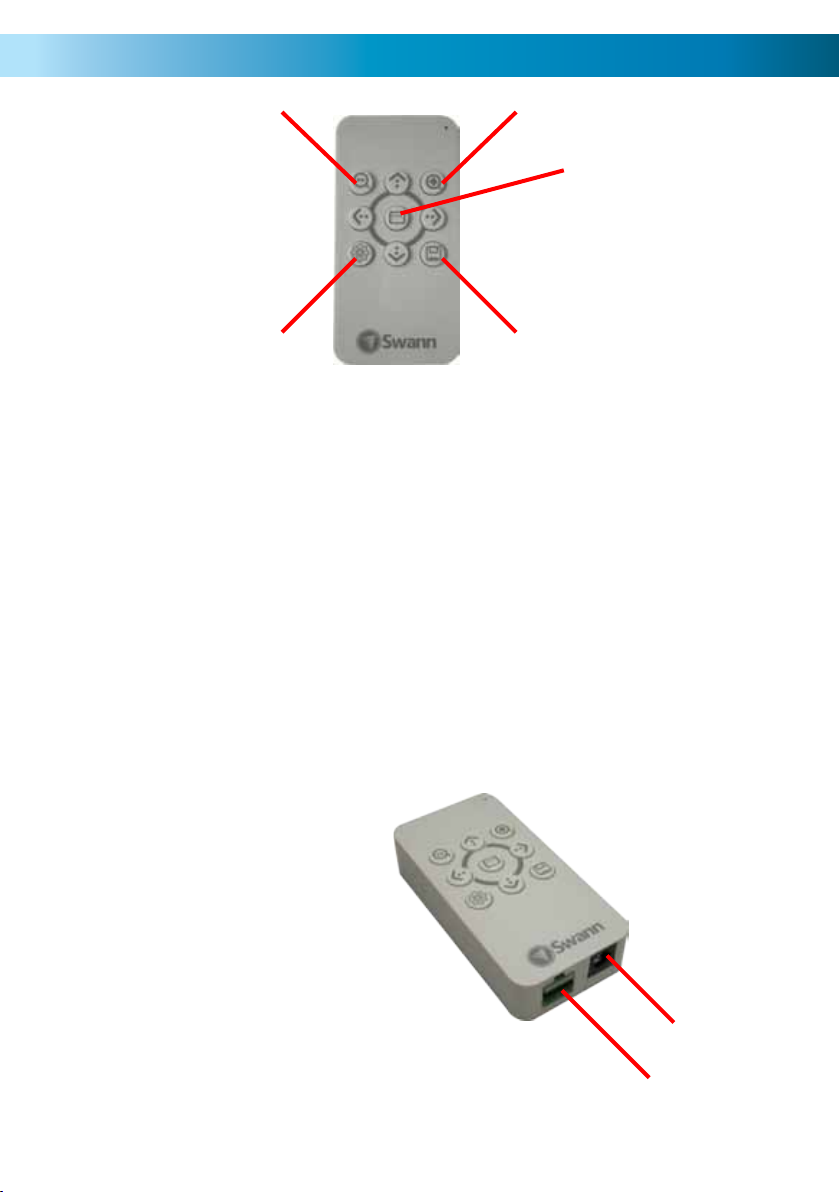
The RS485 Controller
Quick Adjust -
Arrow Buttons
The arrows are
used to navigate
through the main
menu.
Using the Quick Configuration
The Quick Config button will give you instant access to the following settings:
1. DYNAMIC: Digital Wide Dynamic Range (DWDR) [page 10]
2. CONTRAST [page 14]
3. SHARPNESS [page 14]
4. BRIGHTNESS [page 9]
5. AUTO BW AT NIGHT: When disabled, the camera will attempt
to create color images at night. This can result in increased color
information at the cost of image quality.
• These settings are exactly the same as the ones in the Main Menu.
• Cycle through these settings by pressing the Quick Config button repeatedly.
• The Quick Adjust buttons will change the setting you’ve currently selected.
• To confirm a change and exit the Quick Configuration screen, click Save
Quick Config.
Quick Adjust +
Main Menu
Save Quick ConfigQuick Config
Connecting the OSD Controller
The two connections (RS485 and DC
12V) are located on the bottom of
the controller.
Use the supplied RS485 jack and
power splitter to connect the
controller. A complete connection
diagram is located on pages 4 - 5.
DC 12V In
RS485 Port
3
Page 4
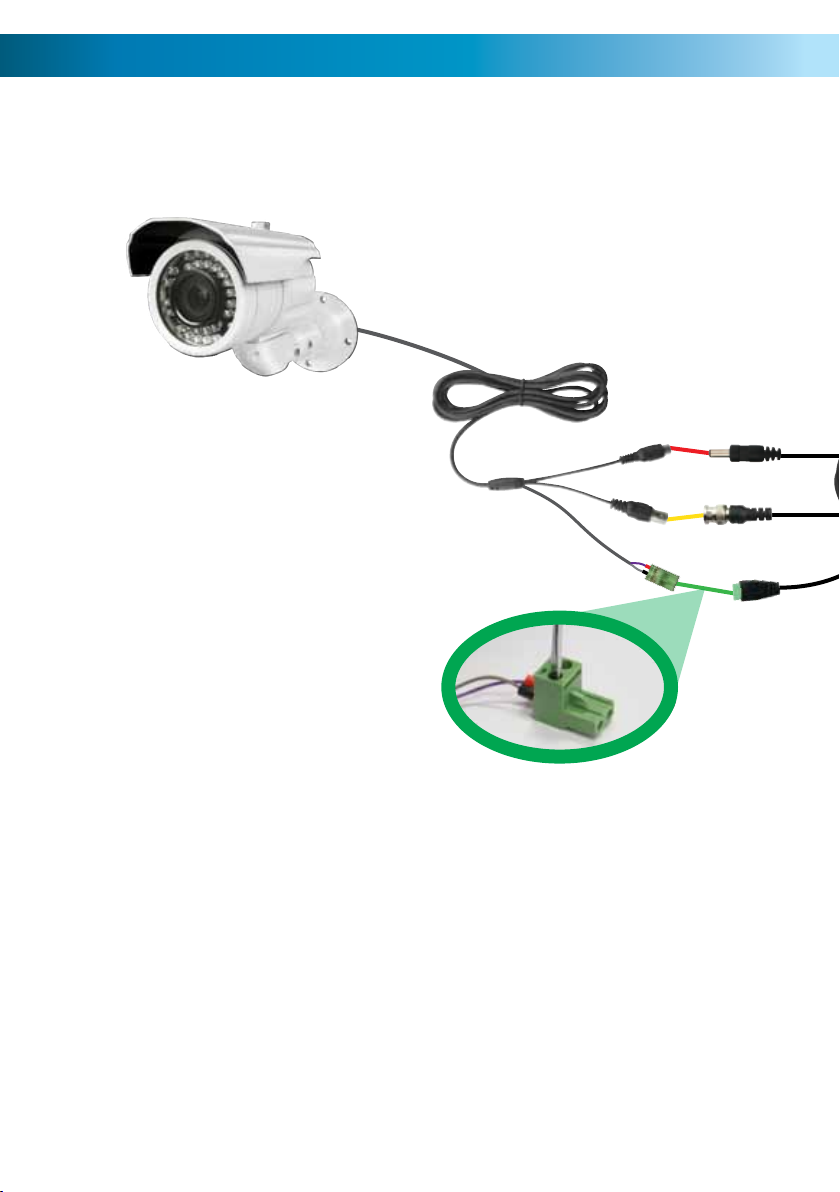
Connection Guide
1. Connect the DC in plug on the
camera cable to the DC out pin
on the end of the extension cable.
1
2
2. Connect the BNC connector on
the camera cable to the BNC
connector on the extension cable.
3. Plug the green RS485 plug on
the end of the camera cable to
the RS485 port on the extension
cable. You may need to connect
the two wires to the RS485 plug.
(See insert, above right).
4. Plug the RS485 connector on the far end of the extension cable into the PTZ
controller. As with step 3, the plug may have to be connected to the wire
terminals.
5. Connect the BNC Output on the end of the extension cable to your video
monitoring/recording device (typically a DVR).
6. Connect one output from the power splitter to the DC in plug on the end of
the extension cable.
7. Connect the other output of the power splitter to the DC in plug on the OSD
controller.
8. Connect the power splitter’s DC in plug to the DC output jack on the power
adapter, and connect the power adapter to a wall socket.
3
4
Page 5
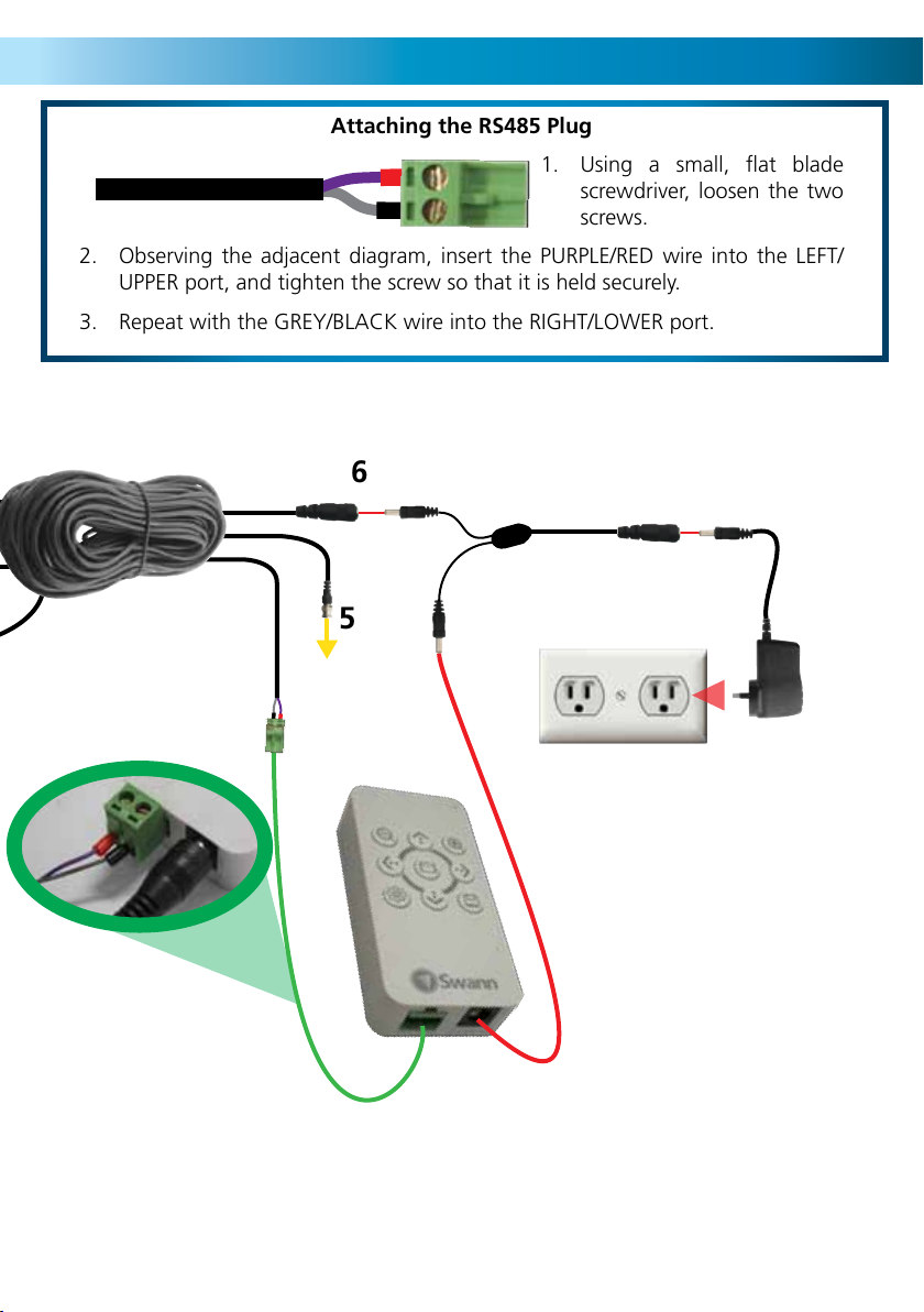
Attaching the RS485 Plug
1. Using a small, flat blade
screwdriver, loosen the two
screws.
2. Observing the adjacent diagram, insert the PURPLE/RED wire into the LEFT/
UPPER port, and tighten the screw so that it is held securely.
3. Repeat with the GREY/BLACK wire into the RIGHT/LOWER port.
6
8
5
7
4
5
Page 6
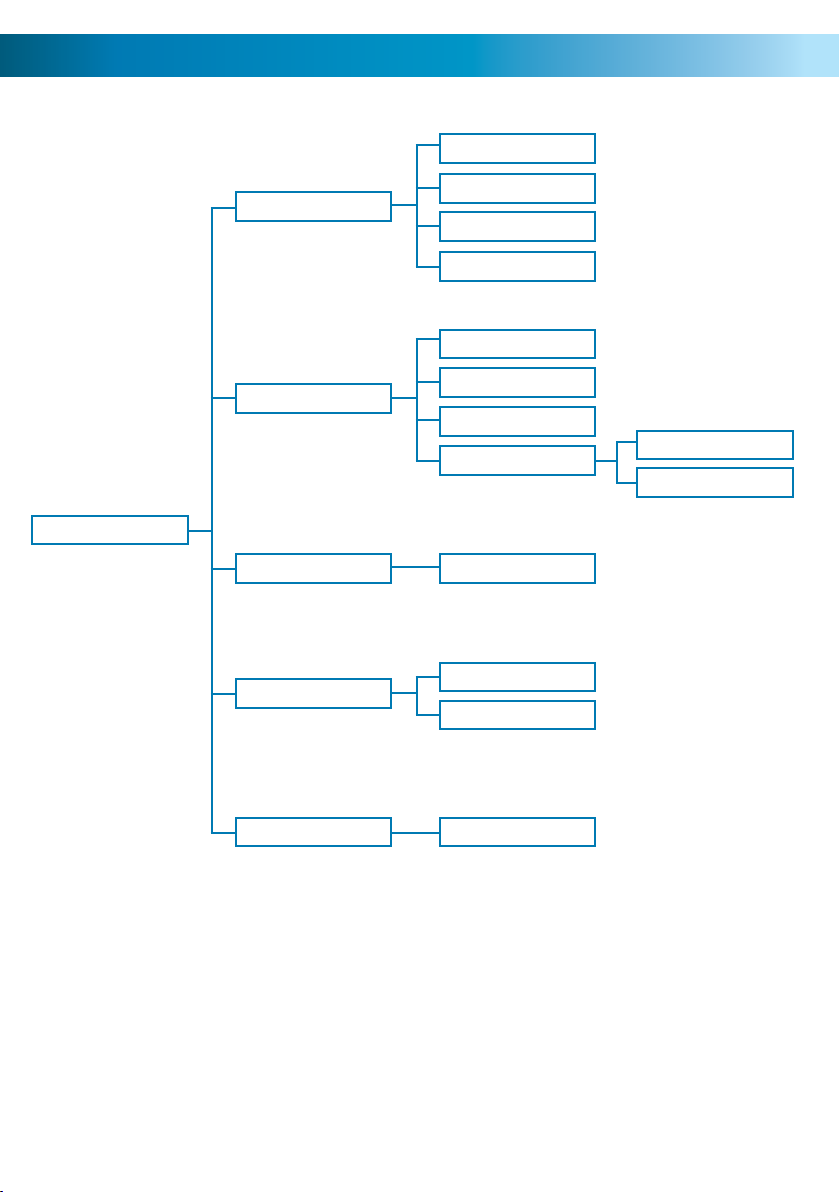
Menu Structure
Shutter
Setup
Exposure
Special
White Balance
Backlight
Brightness
AGC
DWDR
Cam Title
Motion
Privacy
Image Adj
WB Manual
BLC
HLC
Font Color
Display
Reset Factory Default
6
Page 7

Setup (Main) Menu
Exposure: Controls how sensitive the camera will be to light. Press SELECT to
enter the Exposure sub-menu (page 9) to access the detailed exposure controls.
Note: As the cameras have fixed iris lenses, control over exposure is determined
by the electronic shutter (that is, how long each frame is “exposed” for). Unlike
manually altering an iris, this setting will have no effect on your depth of field (how
much of your image is in focus).
Special: Accesses the Special submenu, where many of the unique features of the
OSD can be found (such as options to set the camera’s on-screen Title, adjusting
the way the camera responds to Motion and allows you to access the detailed
Image Adjustment submenu). For more information, see the Special Menu section
on page 11.
White Balance: Controls how the camera interprets and displays colors. There are
a few settings, which are as follows:
AW1 (Automatic White Balance 1): The default setting, which will attempt to create
as neutral a white balance as possible. Colors tend to be slightly underexposed,
but represented quite accurately. The color of the light will have less of an effect
on how the camera perceives color.
AW2 (Automatic White Balance 2): The other automatic option for white balance
control. Rather than attempting to automatically correct for the hue of the light
(technically known as the “color temperature”) the camera attempts to accurately
represent what it can see as the human eye would perceive the same scenario. As
a result, images captured under daylight will seem slightly blue, whereas images
captured under artificial lighting will be tinted yellow (for tungsten filaments) or
green (for many fluorescent tubes).
7
Page 8

Setup Menu: Continued
AWC --> SET: Allows you to create a custom white balance. You’ll need a sheet of
thick white card/paper. Hold the paper in front of the camera so that it covers just
over half the viewing area. If you are using a camera with a vari-focal lens (such as
the PRO-680/681) adjust the focus so that the piece of paper’s edge is sharp and
clear. Then, press SELECT. The camera will use the white card/paper to ascertain
the color of the light, and will adjust itself accordingly.
Manual: Click SELECT to open the Manual White Balance control menu. Here,
you’ll be able to have full control of how the camera determines color. For a
rundown of the Manual White Balance Control menu, see page 19.
Backlight: Controls what part of your images the camera will try and properly
represent, and how it responds to really bright lights.
OFF: The default setting. The camera will try and expose the whole scene evenly.
This may cause some areas to black out (under-expose) or white out (over-expose).
BLC (Backlight Compensation): The camera will try to expose things in the
foreground properly, even if this means that the background will over-expose/
white out. Press SELECT to open the BLC Menu, where you can fine-tune how the
camera responds to backlighting.
HLC (Highlight Compensation): Places a black mask over extreme highlights in your
images. It can be useful to block out, for example, a bright window during the day
or car headlights at night. Press SELECT to open the HLC menu to control how and
when highlight masking will occur.
Reset: Possibly the most important menu item of them all! If you find that the
camera is behaving strangely, then chances are something has been set amiss.
8
Page 9

Exposure Menu
From the EXPOSURE menu, you can control how the camera reacts to lighting
conditions.
SHUTTER: This setting controls the behaviour of the electronic shutter. In a
nutshell, it controls how long the camera will expose each frame. The longer that
the electronic shutter is “open”, the more light it will let in.
We recommend leaving this on AUTO (this will adjust the shutter speed
automatically). Only on rare occasions will AUTO not prove the best option however, these are so infrequent as to be almost unmentionable.
BRIGHTNESS: How light/dark the images coming from the camera will be. Unlike
the SHUTTER setting, this won’t affect how much light the camera needs to see to
create a high quality image. Rather, it affects how the camera processes the images
once they’ve been captured.
Increasing the BRIGHTNESS setting can be useful if you have an unusually dark
monitor/television, or are trying to view images in a very bright environment.
Typically, the default value is fine unless you have specific problems you’re trying
to overcome.
AGC (Automatic Gain Control): Gain is a fancy term for amplifying a video
signal. It works in a similar way to amplifying music – the higher the gain, the
louder/brighter your images will be, but so will the background “noise” (in video
terms, “noise” refers to the random, grainy speckles that appear in images).
When should you decrease/increase the gain? Well, probably never. The MIDDLE
gain control is reliable and quite accurate. Only in the event of extremely unusual
lighting conditions or a very non-standard monitor/television should the automatic
gain control be adjusted.
9
Page 10

DWDR Menu
DWDR (Digital Wide Dynamic Range) Menu
You can change and set the way that the camera captures and represents different
lighting conditions.
LEVEL: The higher you set the LEVEL, the more dynamic your images can be. It
works by changing how the camera interprets data from the CCD (the actual
image sensor). If this setting is low, then bright areas will have a tendency to
“white out” while shadows will do the opposite and “black out”. The higher you
set the DWDR, then the more the camera will attempt to compensate for this, and
you should get more detail in dynamic lighting scenarios.
In some cases, setting the DWDR Level too high can degrade the quality of your
images, as the camera may try overcompensating when it doesn’t need to.
10
Page 11

Special Menu
‘Special’ Menu
CAM TITLE: You can give your camera a name, if you’d like to. There’s no
requirement to do so, but it can make identifying which video feed you’re viewing
on a multiple camera setup easy to determine at a glance. It’s also kind of nice to
feel like the camera is your friend.
MOTION: The camera is able to detect motion, and to highlight the areas where
motion is detected. For more information, see page 12.
PRIVACY: You can apply a privacy mask to any area of the screen you choose.
Selecting this option will open the PRIVACY sub-menu where you’ll be able to
configure how and where the privacy mask will be applied.
Remember , if you apply a privacy mask in-camera and then record the images,
the images will always have the privacy mask superimposed – you won’t be able
to remove it! A better option is to apply a privacy setting on your DVR (if your DVR
supports it).
The Swann DVR-2600 series and the DVR-2550 series support privacy masking.
11
Page 12

Motion Menu
AREA SELECT: Choose which areas of the camera’s view that you’d like to
configure. You can have up to four areas defined and active simultaneously, which
can overlap or be quite discrete.
AREA STATE: Whether the area has motion detection enabled or not. A disabled
area retains its border definitions, size and placement, but will simply not register
activities. Disabling an area will have no effect on other motion sensitive areas it
happens to overlap.
HEIGHT: How high the area you’re editing will be.
LEFT/RIGHT: Where the area you’re editing will be located along the horizontal
axis.
TOP/BOTTOM: Where the area you’re editing will be located along the vertical
axis.
DEGREE: The amount of motion that needs to be detected before the camera
will register it as motion. The higher the setting, the more motion needs to occur
before the camera will highlight it.
VIEW: Whether or not the area will be visible when motion is detected.
12
Page 13

Image Adjustment Menu
IMAGE ADJ.: The Image Adjustment menu allows you to control many aspects of
the camera’s pictures.
LENS SHAD.: If your lens is exposed to direct light, the LENS SHADE option can
improve the quality of your images. When this is ON, the camera will automatically
adjust the content of your images to remove as much as possible of the direct light.
Note: The Lens Shading feature is a quick-fix, and won’t completely correct for
direct light entering the lens. Of course, the best way to improve the quality of
your images is to ensure that light from an intense source (such as the sun) doesn’t
enter the lens directly.
2DNR (Second Level Digital Noise Reduction): DNR is a process whereby the
camera is able to improve the quality of your video images if they appear “noisy”.
The camera employs a noise reduction algorithm all the time (it’s a standard feature
of these cameras and others like them) – this option doubles the amount of noise
reduction.
MIRROR: Flips the image horizontally, like looking at it in a mirror.
13
Page 14

Image Adjustment Menu: Continued
FONT COLOR: What colors the on-screen text will be.
There are fifteen options, the default (white) is #3. The text will always have a black
border.
CONTRAST: Controls the dynamic range of the camera’s output. The higher the
contrast, the greater the difference between the blackest black and the whitest
white will be. Note that this setting will have no bearing on how the camera
actually captures images in situations with harsh lighting. Also, setting the contrast
too high will degrade the quality of your images and introduce digital noise and
grain into your images.
SHARPNESS: How crisp your images will be. Setting the sharpness too high will
make your pictures look pixilated, like old computer graphics. On the other hand,
setting the sharpness too low will make everything look soft and blurry – a bit like
looking through lightly frosted glass.
DISPLAY: Here you can customise the camera’s output specifically for the type
of monitoring device you have connected. For old-school televisions or bulky
computer monitors, choose CRT. For more modern screens, LCD is typically the
best choice. If you are using an unusual type of monitor (such as oLED or plasma)
you’ll probably have to experiment to see what works best on your screen.
NEG. IMAGE (Negative Image): Reverses the colors and luminance of the image.
So, white becomes black, black becomes white and so on. We would generally
recommend not using this setting – you can always invert the color later, anyway.
However, sometimes (particularly monitoring video feeds with low contrast) the
negative image function can make details more apparent to the eye.
14
Page 15

CRT Adjustment Menu
PED LEVEL: Altering the PED level will slightly alter the output voltage of the
composite video out, altering the way that a CRT monitor will build images by
combining the red, green and blue pixels on screen. Higher values will give brighter
images, particularly in darker areas of greyscale. This is an expert feature – we’d
recommend not touching it unless you know exactly what you’re doing.
COLOR GAIN: The amount of color in the video signal. As different televisions and
monitors have different native saturation levels (LCDs are typically less saturated
than a CRT, for example) you might need to adjust the level here to get “natural”
looking images. Remember, you don’t need rich, vivid images for the purposes
of security footage – sometimes lowering the saturation creates a sharper image
which might be more useful for identifying fine details or recognising individuals.
15
Page 16

LCD Adjustment Menu
GAMMA: Allows you to fine tune the gamma reproduction curve of your monitor.
This is an expert feature, and intended for advanced users only. If you want to make
adjustments to your images, we suggest using the Image Adjustment menu and
the options located therein: the vast majority of outcomes achievable by using the
GAMMA adjustment setting here can also be achieved, more easily and accurately,
by tweaking the Brightness and Contrast settings on the ProcAmp.
PED LEVEL: Altering the PED level will slightly alter the output voltage of the
composite video out, altering the way that an LCD monitor will build images by
combining the red, green and blue sub-pixels on screen. Higher values will give
brighter images, particularly in darker areas of greyscale. This is an expert feature
– we’d recommend not touching it unless you know exactly what you’re doing.
COLOR GAIN: The amount of color in the video signal. As different televisions and
monitors have different native saturation levels (LCDs are typically less saturated
than a CRT, for example) you might need to adjust the level here to get “natural”
looking images. Remember, you don’t need rich, vivid images for the purposes
of security footage – sometimes lowering the saturation creates a sharper image
which might be more useful for identifying fine details or recognizing individuals.
16
Page 17

Backlight Compensation Menu (BLC)
AREA SELECT: Choose which areas of the camera’s view that you’d like to
configure. You can have up to four areas defined and active simultaneously, which
can overlap or be quite discrete.
AREA STATE: Whether the area has backlight compensation enabled or not. A
disabled area retains its border definitions, size and placement, but will simply not
register activities. Disabling an area will have no effect on other motion sensitive
areas it happens to overlap.
HEIGHT: How high the area you’re editing will be.
LEFT/RIGHT: Where the area you’re editing will be located along the horizontal
axis.
TOP/BOTTOM: Where the area you’re editing will be located along the vertical
axis.
17
Page 18

Highlight Compensation Menu (HLC)
LEVEL: Sets when highlights will be masked. The lower the value, the lower the
required luminance value will be for the camera to mask it, and thus the more
areas of the screen will be masked.
MODE: You can choose when HLC will be active. ALL DAY will leave HLC on
at all times, whereas selecting NIGHT ONLY will leave highlights during the day
unaffected - this is a good option if you’re looking to mask, for example, car
headlights or an inconveniently placed street lamp.
18
Page 19

Manual White Balance Menu
COLOR TEMP: Color temperature (technically measured in degrees kelvin) is a
measurement of the average wavelength of light being photographed.
Artificial lights (particularly older style tugnsten bulbs) have a low color temperature,
somewhere between 3000°K and 3500°K, and this appears to be an orange/yellow
color. The INDOOR setting will compensate for this, allowing the camera to more
accurately represent color, despite the yellow light.
Sunlight, on a clear day, has a higher color temperature (about 5600°K) and
appears slightly blue. The OUTDOOR setting will accurately represent colors under
these conditions.
BLUE/RED: You can make alterations to the color mix here. Changing these values
directly alters the mix of RED, GREEN and BLUE in your signal. The lower the
values, the less of these colors you will have and, of course, the inverse is true.
There is no direct way to control the amount of green in your signal - however, it
is easy to do. To increase the amount of green, decrease the amount of red and
blue. To decrease the amount of green, increase both the red and blue channels.
19
Page 20

Helpdesk / Technical Support Details
All Countries E-mail: tech@swannsecurity.com
USA toll free
1-800-627-2799
(Su, 2pm-10pm US PT)
(M-Th, 6am-10pm US PT)
(F 6am-2pm US PT)
USA Exchange & Repairs
1-800-627-2799 (Option 1)
(M-F, 9am-5pm US PT)
See http://www.worldtimeserver.com for information on time zones and the current time in
Melbourne, Australia compared to your local time.
Swann Technical Support
Telephone Helpdesk
AUSTRALIA toll free
1300 138 324
(M 9am-5pm AUS ET)
(Tu-F 1am-5pm AUS ET)
(Sa 1am-9am AUS ET)
NEW ZEALAND toll free
0800 479 266
UK
0203 027 0979
Warranty Information
Swann Communications USA Inc.
12636 Clark Street
Santa Fe Springs CA 90670
USA
Swann Communications warrants this product against defects in workmanship and material for a period of
one (1) year from it’s original purchase date. You must present your receipt as proof of date of purchase for
warranty validation. Any unit which proves defective during the stated period will be repaired without charge
for parts or labour or replaced at the sole discretion of Swann. The end user is responsible for all freight
charges incurred to send the product to Swann’s repair centres. The end user is responsible for all shipping
costs incurred when shipping from and to any country other than the country of origin.
The warranty does not cover any incidental, accidental or consequential damages arising from the use of
or the inability to use this product. Any costs associated with the fitting or removal of this product by a
tradesman or other person or any other costs associated with its use are the responsibility of the end user.
This warranty applies to the original purchaser of the product only and is not transferable to any third party.
Unauthorized end user or third party modifications to any component or evidence of misuse or abuse of the
By law some countries do not allow limitations on certain exclusions in this warranty. Where applicable by
local laws, regulations and legal rights will take precedence.
This equipment has been tested and found to comply with the limits for Class B digital device, pursuant to part 15 of
the FCC Rules. These limits are designed to provide reasonable protection against harmful interference in a residential
installation. This equipment generates, uses and can radiate radio frequency energy and, if not installed and used
in accordance with the instructions, may cause harmful interference to radio or television reception, which can be
determined by turning the equipment off and on, the user is encouraged to try to correct the interference by one or
more of the following measures:
• Reorient or relocate the receiving antenna
• Increase the separation between the equipment and the receiver
• Connect the equipment into an outlet on a circuit different from that to which the receiver is connected
• Consult the dealer or an experienced radio/TV technician for help
WARNING: Modifications not approved by the party responsible for compliance could void user’s authority to
Swann Communications
Unit 13, 331 Ingles Street,
Port Melbourne Vic 3207
device will render all warranties void.
© Swann Communications 2011
FCC Verification
operate the equipment.
Swann Communications LTD.
Stag Gates House
63/64 The Avenue
SO171XS
United Kingdom
 Loading...