

Page 1
PRO-640
Security Camera
M640CAM180412T
Page 2

2
Before you begin
Introduction
Congratulations on your purchase of this PRO-640 indoor/outdoor day & night CCTV camera
from Swann. The PRO-640 is a color CCD camera that can operate in almost all lighting
conditions, from bright daylight (provided it’s not pointed straight toward the sun!) to pitch
darkness.
The PRO-640 is very sensitive to light and therefore can make use of even the smallest amount
of light to provide an image of what it sees. In low light, this comes through as a black and
white image.
In complete or near-total darkness, the camera uses built-in infrared LEDs to illuminate the
area in front of it. This light is invisible to the human eye, although you might notice a faint red
glow coming from the front of the camera - this is normal.
In day or well lit environments, the IR Cut Filter feature of the camera activates to lter out
wavelengths of light the camera does not need in order to provide a clear color image.
IMPORTANT NOTE:
All jurisdictions have specic laws and regulations relating to the use of cameras. Before using
any camera for any purpose, it is the buyer’s responsibility to be aware of all applicable laws
and regulations that prohibit or limit the use of cameras and to comply with the applicable
laws and regulations.
WARNING: Modications not approved by the party responsible for compliance could void
user’s authority to operate the equipment.
IMPORTANT SAFETY INSTRUCTIONS:
• Make sure product is xed correctly and stable if fastened in place
• Do not operate if wires and terminals are exposed
Page 3
3
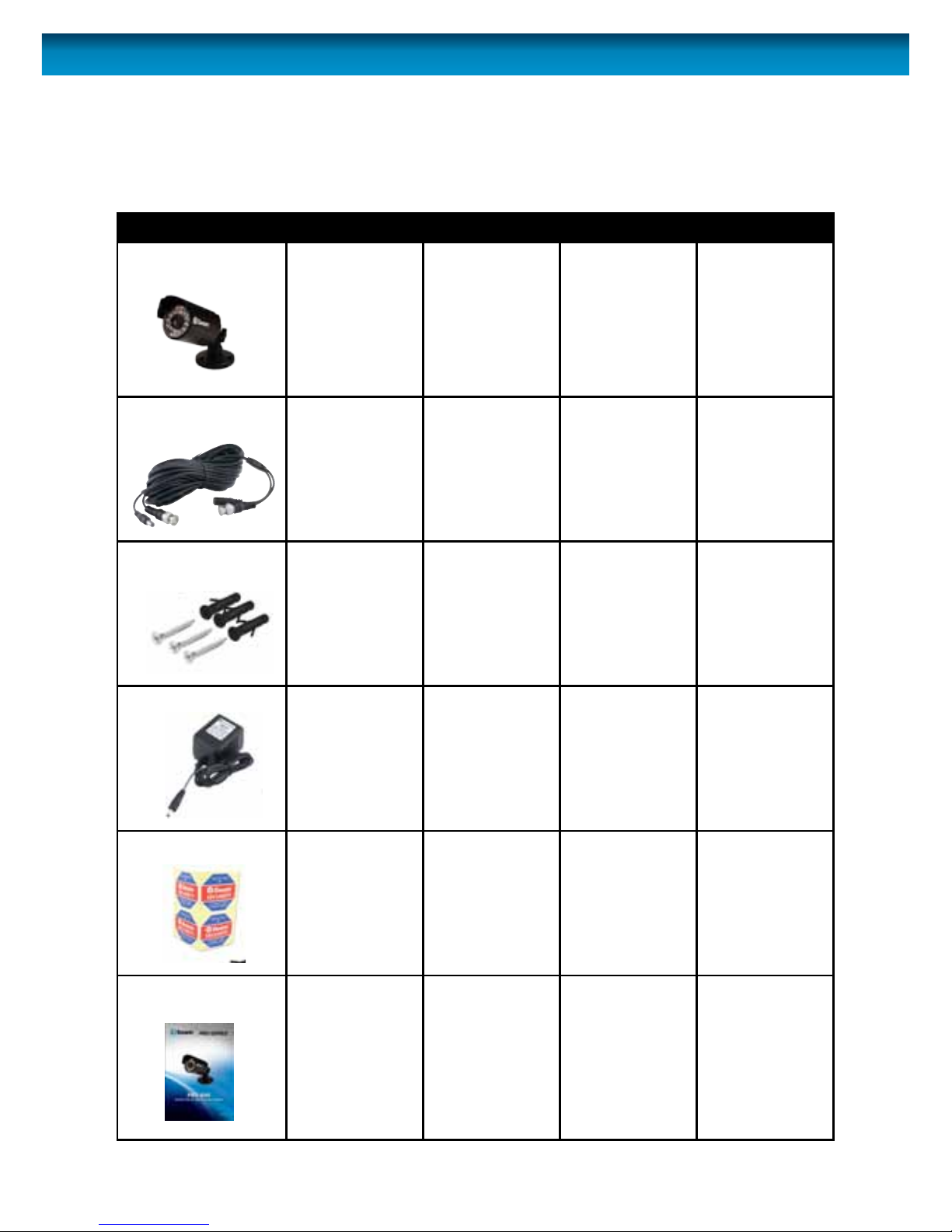
Package Contents
Pack contents:
You may have purchased your PRO-640 as a standalone camera or as part of a pack. This will
dictate the expected contents you should have received with your camera.
Item Single camera 2 camera pack 3 camera pack 4 camera pack
PRO-640 camera 1 2 3 4
Extension cable 1 2 3 4
Screws and wall plug
package
1 2 3 4
Power Adapter 1 1 (with 2-way
power splitter
cable)
1 (with 4-way
power splitter
cable)
1 (with 4-way
power splitter
cable)
Security stickers 4 4 4 4
Operating
Instructions
1 1 1 1
Page 4
4
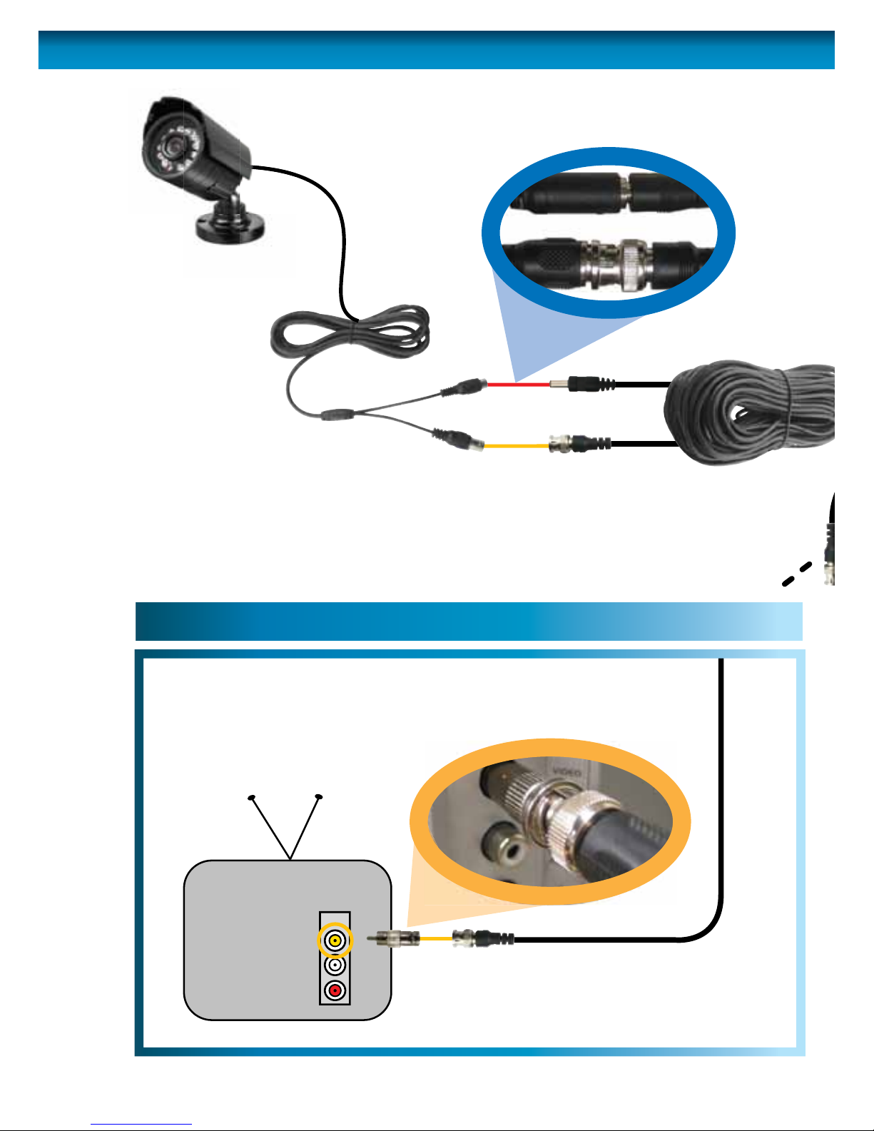
Connection Guide
Connect the camera’s DC
and BNC socket cable to the
extension cable’s DC and BNC plugs
1
3A
3B
INPUT
2A. Connecting Directly to TV
2B. Connecting to Your Existing DVR
Connect a BNC to RCA
adapter and connect to video
input on your TV or VCR
2
Page 5

5
Connection Guide
Plug in the camera
power adapter into
a wall socket
4
FOR A SINGLE CAMERA
Connect the extension cable’s
DC socket to the DC plug on
the power adapter
3A
FOR 4 CAMERA PACKS
Connect the extension cable’s
DC socket to one of the four
sockets on the power splitter.
Then, plug the single end of the
power splitter to the DC plug
on the power adaptor.
3B
2B. Connecting to Your Existing DVR
Connect the BNC extension
cable to an open channel on
the back of the DVR
2
Page 6
6
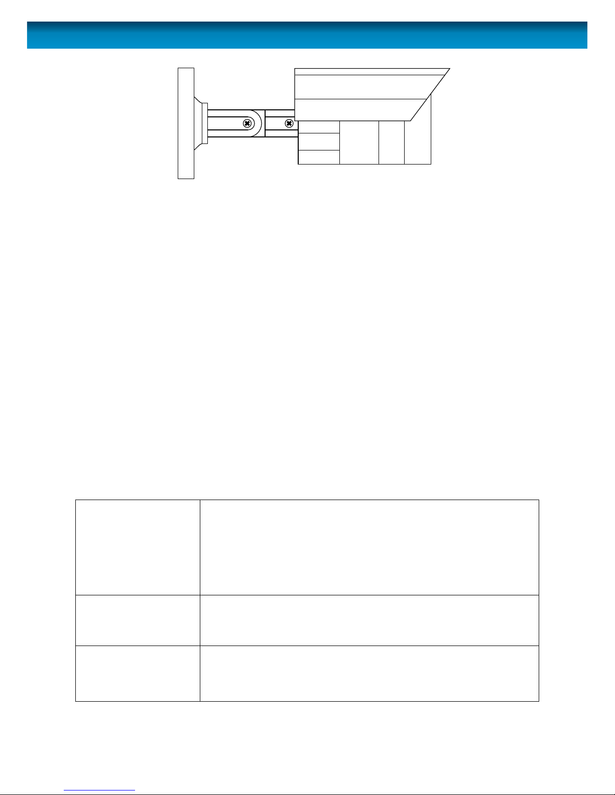
Mounting the camera
The stand on the PRO-640 is deceptively adaptable. At rst glance it may appear to limit how
many options you have when mounting and aiming the camera, but this is simply untrue. The
PRO-640 stand is almost innitely adaptable – it’s like the Rubik’s Cube of CCTV camera stands!
You’ve got three points of articulation. The most obvious is the thumb screw-secured elbow
joint in the centre of the stand (1). This one is pretty obvious and straight forward – loosen the
screw, adjust to the position you want, and then tighten the screw again to secure in place.
The second point of articulation (2) is the radial joint where the neck of the stand attaches to
the base. To adjust this joint, loosen the locking ring by rotating counter-clockwise. Rotate the
camera and stand to the position you want then tighten the locking ring. By using articulation
points 1 and 2, you can aim the camera in virtually any direction.
Point 3, located where the camera attaches to the stand, is held in place by one locking screw.
Like point 2, it is a radial joint, allowing you to rotate the camera so that no matter how points
1 and 2 are congured, the camera can still face upright. Simply loosen the screw, rotate the
camera to the upright position (so that up in your pictures is actually up) then tighten the
screw to lock into place.
Of course, there will always be some outlying cases where the camera and stand simply won’t
t where you want to mount them. Maybe you have a hanging awning, or a drain pipe in an
inconvenient spot. In these cases, we suggest obtaining a mounting bracket, which should be
available from any good hardware store.
Troubleshooting
On my Swann DVR, ‘Video
Loss’ appears where the
image from my camera
should be.
• Check the extension cable (power and video) is securely
connected to the camera.
• Check the video output from the camera is securely connected
to a video input channel on the DVR.
• Check the power from the camera is securely connected to a
power supply.
When I view an image
from the camera at night
I only see a bright spot
and no image.
• A reection can be caused in night vision mode if the camera is
looking through a window. Move the camera to the other side
of the window or to another location.
The BNC extension cable
will not connect to my TV.
• Many TV’s and monitors do not have a BNC connector but do
have an RCA connector. Connect a BNC to RCA adapter to the
end of the extension cable and then plug into the RCA socket
on your TV or monitor.
2
31
Page 7

7
Images are for illustrative purposes only.
Specications subject to change without notice.
For the latest version of this manual, please visit:
www.swann.com
Video
Image Sensor 1/3” CCD
Video Quality 600 TVL
Resolution PAL: 752x582 / NTSC:768x494
Minimum Illumination 0 Lux (IR on)
Day/Night Mode Color in lit areas / Black & White in dark areas
White Balance Automatic
Signal / Noise Ratio 45db
Gain Control Automatic
Backlight Compensation Yes
Lens 6.0mm
Viewing Angle Avg: 38° (H: 33°, V: 43°)
Night Vision
Night Vision Distance 65ft/20m
IR Cut Filter No
Infra-red LEDs 24
Infra-red wavelength 850nm
Infra-red LED life (average) 10,000 hours
General
Indoor/Outdoor Both
Operating Power DC 12V
Operating Temperature -20°C ~ 60°C / -4°F ~ 140°F
Body Construction Aluminium
Dimensions (without stand)
50mm x 50mm x 60mm
2.0” x 2.0” x 2.3”
Dimensions (with stand)
59mm x 59mm x 137mm
2.3” x 2.3 ” x 5.3”
Weight 230g / 8.11oz
Page 8
© Swann Communications 2012
Helpdesk / Technical Support Details
Limited Warranty Terms & Conditions
Swann Communications warrants this product against defects in workmanship and material for a period
of one (1) year from it’s original purchase date. You must present your receipt as proof of date of purchase
for warranty validation. Any unit which proves defective during the stated period will be repaired without
charge for parts or labour or replaced at the sole discretion of Swann. The end user is responsible for all
freight charges incurred to send the product to Swann’s repair centres. The end user is responsible for all
shipping costs incurred when shipping from and to any country other than the country of origin.
The warranty does not cover any incidental, accidental or consequential damages arising from the use of
or the inability to use this product. Any costs associated with the tting or removal of this product by a
tradesman or other person or any other costs associated with its use are the responsibility of the end user.
This warranty applies to the original purchaser of the product only and is not transferable to any third
party. Unauthorized end user or third party modications to any component or evidence of misuse or
abuse of the device will render all warranties void.
By law some countries do not allow limitations on certain exclusions in this warranty. Where applicable by
local laws, regulations and legal rights will take precedence.
For Australia: Our goods come with guarantees which cannot be excluded under Australian Consumer
Law. You are entitled to a replacement or refund for a major failure and for compensation for any other
reasonably foreseeable loss or damage. You are also entitled to have the goods repaired or replaced if the
goods fail to be of acceptable quality and the failure does not amount to major failure.
Swann Technical Support
All Countries E-mail: tech@swannsecurity.com
Telephone Helpdesk
USA toll free
1-800-627-2799
(Su, 2pm-10pm US PT)
(M-Th, 6am-10pm US PT)
(F 6am-2pm US PT)
USA Exchange & Repairs
1-800-627-2799 (Option 1)
(M-F, 9am-5pm US PT)
AUSTRALIA toll free
1300 138 324
(M 9am-5pm AUS ET)
(Tu-F 1am-5pm AUS ET)
(Sa 1am-9am AUS ET)
NEW ZEALAND toll free
0800 479 266
UK
0203 027 0979
See http://www.worldtimeserver.com for information on time zones and the
current time in Melbourne, Australia compared to your local time.
FCC Verication
This equipment has been tested and found to comply with the limits for Class B digital device, pursuant
to part 15 of the FCC Rules. These limits are designed to provide reasonable protection against harmful
interference in a residential installation. This equipment generates, uses and can radiate radio frequency
energy and, if not installed and used in accordance with the instructions, may cause harmful interference
to radio or television reception, which can be determined by turning the equipment o and on, the user is
encouraged to try to correct the interference by one or more of the following measures:
Reorient or relocate the receiving antenna
Increase the separation between the equipment and the receiver
•Connecttheequipmentintoanoutletonacircuitdierentfromthattowhichthereceiverisconnected
•Consultthedealeroranexperiencedradio/TVtechnicianforhelp
WARNING: Modications not approved by the party responsible for compliance could void user’s authority
to operate the equipment.
Page 9

PRO-640
Cámara de seguridad
Page 10

10
Antes de que Comience
Introducción
La PRO-640 es una cámara color CCD que se puede usar de día o en ambientes de poca luz,
como en interiores o a la noche.
La PRO-640 es ultra sensible a la luz y, por eso, puede hacer uso de incluso la menor cantidad
de luz para proporcionar una imagen de lo que ve. En ambientes poco iluminados, esto resulta
en una imagen en blanco y negro.
En la oscuridad completa o casi total, la cámara utiliza el incorporado en LED infrarrojos para
iluminar la zona en frente de ella. Esta luz es invisible al ojo humano, aunque es posible que
note un tenue resplandor rojo que viene desde la parte frontal de la cámara - esto es normal.
En los entornos de día o bien iluminado, la función de ltro de corte IR de la cámara se activa
para ltrar longitudes de onda de la luz de la cámara no necesita a n de proporcionar una
imagen en color claro.
NOTA IMPORTANTE:
Todas las jurisdicciones tienen leyes y reglamentos especícos relacionados al uso de cámaras.
Antes de usar cualquier cámara para cualquier propósito, es la responsabilidad del comprado
el estar conciente de cualquier ley y reglamento aplicables que prohíban o limiten el uso de
cámaras y para cumplir con leyes y reglamentos aplicables.
ADVERTENCIA: Las modicaciones no aprobadas por la parte responsable de su
cumplimiento puede cancelar la autoridad del usuario para usar el equipo.
INSTRUCCIONES IMPORTANTES DE SEGURIDAD:
• Asegúrese que el producto se je correctamente y esté estable si es sujetado en su lugar.
• No use si los cables y las terminales están expuestas.
Page 11

11
Pack contents:
Usted pudo haber comprado su PRO-640 como una cámara independiente o como parte
de un paquete. Esto impondrá los contenidos esperados que debería haber recibido con su
cámara.
Item 1 Cámara 2 Cámara 3 Cámara 4 Cámara
Cámara PRO-640 1 2 3 4
Cable de extensión 1 2 3 4
Tornillos de Montaje y
Taquetes
1 2 3 4
Adaptador de
Corriente
1 1 (con divisor de
Corriente)
1 (con divisor de
Corriente)
1 (con divisor de
Corriente)
Marquillas de
seguridad
4 4 4 4
Instrucciones de Uso 1 1 1 1
Contenido del Paquete
Page 12

12
1
3A
3B
2A. Conectando Directamente a la TV 2B. Conectando su DVR Existente
Conecte el cable de toma DC y
BNC a los enchufes DC y BNC del
cable de de extensión.
Conecte el enchufe BNC en el cable de extensión en la toma
BNC en el adaptador RCA a BNC. Luego conecte el enchufe
RCA en el adaptador RCA a BNC (que debe conectarse al
cable de extensión) a la conexión de ENTRADA DE VIDEO
en la parte posterior de su TV.
INPUT
2
Guía de Conexión
Page 13

13
Guía de Conexión
4
3A
CÁMARA DE 4 paquetes de
Conecte los cables de extensión de
To ma de CC a una de las cuatro
tomas de corriente en el divisor de potencia.
A continuación, conecte el único fin de la
separador de alimentación a la clavija de cc
en el adaptador de corriente.
3B
Conecte el
adaptador de
corriente de la
cámara a la
toma de la
pared.
Conecte la toma DC de los
cables de extensión al enchufe
DC en el adaptador de corriente.
Conecte el enchufe BNC de los cables de
extensión a la toma BNC (CH1, CH2, CH3
o CH4) en la parte posterior del DVR.
2
Page 14

14
Montaje de la Cámara
Le support sur le PRO-640 est faussement adaptable. À première vue il semble limiter le
nombre d’options que vous avez lorsque vous assemblez et ciblez la caméra, mais cela est
simplement faux. Le support PRO-640 est presqu’inniment adaptable – c’est comme le Cube
Rubik des supports de caméra de CCTV!
Vous avez trois points d’articulation. Le plus évident est le joint du coude retenu par une vis
à oreilles au centre du support (1). Celui-ci est vraiment évident et simple – desserrez la vis,
ajustez à la position désirée puis serrez la vis pour xer en place.
Le second point d’articulation (2) est le joint radial où le cou du support s’attache à la base. Pour
ajuster ce joint, desserrez l’anneau de blocage en tournant dans le sens antihoraire. Pivotez la
caméra et le support dans la position désirée puis serrez l’anneau de blocage. En utilisant les
points d’articulation 1 et 2, vous pouvez diriger la caméra dans virtuellement n’importe quelle
direction.
Le point 3, situé où la caméra s’attache au support, est tenu en place par une vis de blocage.
Tout comme le point 2, c’est un joint radial, qui vous permet de pivoter la caméra face vers le
haut, peu importe comment les points 1 et 2 sont congurés. Desserrez simplement la vis,
pivoter la caméra en position verticale (de sorte qu’en haut dans vos images est bien en haut)
puis serrez la vis pour verrouiller en place.
Bien sur, il y aura toujours des cas isolés où la caméra et le support ne pourront simplement pas
être montés où vous voulez les monter. Vous avez peut-être un auvent suspendu, ou un tuyau
d’égout dans un endroit incommode. Dans ces cas, nous suggérons d’obtenir un support de
montage, qui devrait être disponible dans toute bonne quincaillerie.
Resolviendo Problemas
En el equipo DVR de
marca Swann aparece
la leyenda Video Loss
(video perdido), cuando
deberían aparecer las
imágenes de la cámara.
• Revise que el cable de extensión esté debidamente conectado
a la cámara, y que la conexión esté bien hecha en la posterior
del DVR. También asegúrese que la cámara tiene corriente,
conectándola a un Segundo tomacorriente.
Cuando veo mi cámara
en la noche solo veo una
mancha brillante y nada
de imagen.
• La Visión Nocturna se reejará cuando brille a través de una
ventana. Mueva la cámara al otro lado de la ventana o a otra
ubicación.
El Cable de Extensión
BNC no se conecta a mi
televisión.
• Conecte el adaptador BNC a RCA al extreme del Cable de
Extensión y conecte a la televisión.
2
31
Page 15

15
las imágenes son sólo para nes ilustrativos.
Especicaciones sujetas a cambios sin previo aviso.
Para obtener la última versión de este manual, visite:
www.swann.com
Video
Sensor de Imagen CCD de 1/3”
Calidad de Video 600 Líneas de Televisión
Número Efectivo de Pixeles PAL: 752x582 / NTSC:768x494
Iluminación Mínima 0 Lux (IR Encendido)
Modo Día/Noche Color en áreas iluminadas / Blanco y Nego de noche
Balance de Blancos Automático
Relación Señal / Ruido 45db
Control de Ganancia Automático
Compensación por Luz de Fondo Sí
Lente 6.0mm
Ángulo de Visión Avg: 38° (H: 33°, V: 43°)
Visión Nocturna
Distancia con Visión Nocturna 65ft/20m
Filtro de Corte de IR Sí
LEDs Infrarrojos 24
Longitud de Onda de Infrarrojo 850nm
Vida útil del LED infrarrojo 10,000 horas
General
Interiores/Exteriores Ambos
Energía Operativa DC 12V
Temperatura Operativa -20°C ~ 60°C / -4°F ~ 140°F
Construcción de la Cubierta Aluminio
Dimensiones
50mm x 50mm x 60mm
2.0” x 2.0” x 2.3”
Dimensiones – Cámara y Soporte
59mm x 59mm x 137mm
2.3” x 2.3 ” x 5.3”
Peso – Cámara y Soporte 230g / 8.11oz
Page 16

© Swann Communications 2012
Swann Technical Support
All Countries E-mail: tech@swannsecurity.com
Telephone Helpdesk
See http://www.worldtimeserver.com for information on time zones and the
current time in Melbourne, Australia compared to your local time.
USA toll free
1-800-627-2799
(Su, 2pm-10pm US PT)
(M-Th, 6am-10pm US PT)
(F 6am-2pm US PT)
USA Exchange & Repairs
1-800-627-2799 (Option 1)
(M-F, 9am-5pm US PT)
AUSTRALIA toll free
1300 138 324
(M 9am-5pm AUS ET)
(Tu-F 1am-5pm AUS ET)
(Sa 1am-9am AUS ET)
NEW ZEALAND toll free
0800 479 266
UK
0203 027 0979
Swann Communications USA Inc.
12636 Clark Street
Santa Fe Springs CA 90670
USA
Swann Communications
Unit 13, 331 Ingles Street,
Port Melbourne Vic 3207
Swann Communications LTD.
Stag Gates House
63/64 The Avenue
SO171XS
United Kingdom
Vericación de la FCC:
NOTA: Este equipo ha sido probado y se encontró que cumple con los límites para aparatos digitales
Clase B, de acuerdo con la parte 15 de la FCC. Estos límites están diseñados para proveer protección
razonable contra interferencia dañina en una instalación residencial. Este equipo genera, usa y puede
irradiar energía de radiofrecuencia, si no se instala y se usa de acuerdo con las instrucciones, puede causar
interferencia dañina en la recepción de radio o televisión, lo cual se puede determinar encendiendo y
apagando el equipo, se alienta al usuario intentar corregir la interferencia mediante una o más de las
siguientes medidas:
•Reorienteocambiadeubicaciónlaantenareceptora.
•Incrementelaseparaciónentreelequipoyelreceptor.
•Conecteelequipoaunatomaenuncircuitodiferentealqueestáconectadoelreceptor.
•Consultealdistribuidoroauntécnicoenradio/televisiónconexperienciaporayuda.
Estos dispositivos cumplen con la parte 15 del Reglamento de la FCC. El funcionamiento está sujeto a las
dos siguientes condiciones:
(1) Estos aparatos no deben causar interferencia dañina, y
(2) Estos aparatos deben aceptar cualquier interferencia recibida, incluyendo interferencia que pueda
causar un funcionamiento no deseado
Swann Communications garantiza este producto por defectos de fabricación y material,por un período
de un (1) año a partir de la fecha original de compra. Usted deberá presentar su recibo como prueba
de la fecha de compra para validar la garantía. Cualquier unidad que se compruebe defectuosa durante
el período antes citado será reparada sin cobrar los repuestos o la mano de obra, o será sustituida, a
discreción exclusiva de Swann. La reparación o sustitución se garantizará por noventa días o por el período
que falte de la garantía original de un año, el que resulte más largo de los dos. El usuario nal asume los
costos de etes incurrido para enviar el producto a los centros de reparación de Swann. El usuario nal se
responsabiliza de los costos de envío en que incurran cuando envía desde y hacia cualquier país distinto
al país de origen.
La garantía no cubre daños accidentales, circunstanciales o que resulten del uso o la imposibilidad de
utilizar este producto. Cualquier costo asociado con la adaptación o remoción de este producto por parte
de un vendedor o de otra persona, o cualquier costo asociado con el uso del mismo son responsabilidad
del usuario nal. Esta garantía aplica exclusivamente al comprador original del producto, y no es
transferible a terceros.
Si el usuario nal o un tercero hacen modicaciones no autorizadas a cualquier componente o si hay
evidencia de mal uso o abuso del dispositivo, se anularán todas las garantías.
Centro de asistencia técnica
Información sobre la garantía
Page 17

PRO-640
Caméra de sécurité
Page 18

18
Avant de commencer
Introduction
La PRO-640 est une caméra couleur CMOS qui peut fonctionner dans des éclairages de jour ou
de faible intensité tel à l’intérieur ou la nuit.
La PRO-640 est ultra sensible à la lumière et donc peut utiliser une très petite quantité de
lumière pour orir une image de ce qu’elle voit. À faible intensité, l’image apparaît en noir et
blanc.
Dans l’obscurité complète ou quasi-totale, la caméra utilise intégré LED infrarouges pour
éclairer la zone en face de lui. Cette lumière est invisible à l’œil humain, bien que vous
remarquerez peut-être une faible lueur rouge venant de l’avant de la caméra - ce qui est
normal.
Dans les environnements de jour ou bien éclairé, la fonction de ltre IR de la caméra active
pour ltrer les longueurs d’onde de la lumière de la caméra n’a pas besoin an de fournir une
image en couleur claire.
REMARQUE IMPORTANTE:
Chaque juridiction possède des lois et réglementations spéciques encadrant l’utilisation
des caméras. Il est de la responsabilité de l’acheteur, avant d’utiliser toute caméra et ce pour
tout motif, de s’être informé des lois et réglementations applicables encadrant, interdisant ou
limitant l’utilisation des caméras et de se conformer à ces dernières.
AVERTISSEMENT : Les modications non approuvées par la partie responsable de la
conformité peuvent annuler le droit de l’utilisateur d’utiliser cet équipement.
INSTRUCTIONS DE SÉCURITÉ IMPORTANTES :
• S’assurer, si le produit est xé, qu’il le soit bien et de manière stable
• Ne pas utiliser si le câblage ou les bornes sont exposés
Page 19

19
Contenu de l’emballage
Contenu de l’emballage:
Vous avez probablement acheté votre PRO-640 comme simple caméra ou comme faisant
partie d’un ensemble. Ceci dictera le contenu que vous devriez avoir reçu avec votre caméra.
Item Packs Caméra 1 Packs Caméra 2 Packs Caméra 3 Packs Caméra 4
Caméra PRO-640 1 2 3 4
Câble d’extension de
la caméra
1 2 3 4
Vis & prises de
montage
1 2 3 4
Adaptateur de
courant
1 1 (incluant un
séparateur
d’alimentation)
1 (incluant un
séparateur
d’alimentation)
1 (incluant un
séparateur
d’alimentation)
Autocollants de
sécurité
4 4 4 4
Guide de démarrage
rapide
1 1 1 1
Page 20

20
1
3A
3B
Connexion des prises BNC et
DC de la camera aux prises BNC et
DC de la rallonge.
INPUT
2
Branchez la prise BNC de la rallonge dans la prise BNC de
l’adaptateur RCA vers BNC. Connectez alors la prise RCA à
l’adaptateur RCA vers BNC (qui doit être branché à la
rallonge) de la connextion ENTREE VIDEO située à l’arrière
de votre TV.
2A. Connexion TV directe 2B. Connexion à votre DVR
Guide de connexion
Page 21

21
Guide de connexion
4
3A
PACKS POUR 4 CAMERA
Branchez les câbles d'extension
Prise de DC à l'un des quatre
Prises sur le diviseur de puissance.
Ensuite, branchez l'extrémité unique de la
diviseur de puissance à la prise de DC
sur l'adaptateur secteur.
3B
Branchez
l’adaptateur de
la camera dans
une prise murale.
Branchez la prise DC des
câbles d’extension à la prise
DC de l’adaptateur.
Branchez la prise BNC des rallonges à une prise
BNC (CH1, CH2, CH3 ou CH4) à l’arrière
de votre DVR.
2
Page 22

22
Fixation de la caméra
Le support sur le PRO-640 est faussement adaptable. À première vue il semble limiter le
nombre d’options que vous avez lorsque vous assemblez et ciblez la caméra, mais cela est
simplement faux. Le support PRO-640 est presqu’inniment adaptable – c’est comme le Cube
Rubik des supports de caméra de CCTV!
Vous avez trois points d’articulation. Le plus évident est le joint du coude retenu par une vis
à oreilles au centre du support (1). Celui-ci est vraiment évident et simple – desserrez la vis,
ajustez à la position désirée puis serrez la vis pour xer en place.
Le second point d’articulation (2) est le joint radial où le cou du support s’attache à la base. Pour
ajuster ce joint, desserrez l’anneau de blocage en tournant dans le sens antihoraire. Pivotez la
caméra et le support dans la position désirée puis serrez l’anneau de blocage. En utilisant les
points d’articulation 1 et 2, vous pouvez diriger la caméra dans virtuellement n’importe quelle
direction.
Le point 3, situé où la caméra s’attache au support, est tenu en place par une vis de blocage.
Tout comme le point 2, c’est un joint radial, qui vous permet de pivoter la caméra face vers le
haut, peu importe comment les points 1 et 2 sont congurés. Desserrez simplement la vis,
pivoter la caméra en position verticale (de sorte qu’en haut dans vos images est bien en haut)
puis serrez la vis pour verrouiller en place.
Bien sur, il y aura toujours des cas isolés où la caméra et le support ne pourront simplement pas
être montés où vous voulez les monter. Vous avez peut-être un auvent suspendu, ou un tuyau
d’égout dans un endroit incommode. Dans ces cas, nous suggérons d’obtenir un support de
montage, qui devrait être disponible dans toute bonne quincaillerie.
Résolution des problèmes
Problème : Sur mon
DVR Swann, le message
Perte Vidéo apparaît là
où devrait se trouver ma
caméra.
• Solution : Vériez que la rallonge est correctement connectée
à la camera et que les connexions situées à l’arrière du DVR
sont sécurisées. Assurez-vous également que la caméra est
alimentée en essayant une seconde prise électrique.
Problème : De nuit, ma
caméra ne diuse qu’une
grande tache claire,
aucune image.
• Solution : Les ondes infraroues utilisées pour la vision nocturne
peuvent être reétées par les fenêtres ou les miroirs.
• Déplacez votre caméra de l’autre côté de la fenêtre.
Problème : Le câble
d’extension BNC ne peut
pas être branché sur
ma TV.
• Solution : Connectez l’extrémité BNC du câble d’extension à
l’adaptateur RCA.
2
31
Page 23

23
Les images sont à titre indicatif seulement.
Les spécications sont sujettes à changement sans préavis.
Pour la version la plus récente de ce manuel, veuillez visitez :
www.swann.com
Vidéo
Capteur d’image 1/3” CCD
Qualité video 600 lignes TV
Nombre de pixels eectifs PAL: 752x582 / NTSC:768x494
Illumination minimale 0 Lux (IR actif)
Mode jour/nuit
Couleur dans les zones éclairées
Noir et Blanc en mode Nuit
Balance des blancs Automatique
Ratio bruit / signal 45db
Contrôle du gain Automatique
Compensation contre-jour Oui
Lentille 6.0mm
Angle de vue Avg: 38° (H: 33°, V: 43°)
Vision nocturne
Distance vision de nuit 65ft/20m
Filtre IR Oui
LED infrarouges 24
Longueur d’onde infrarouge 850nm
Durée de vie LED infrarouge 10,000 heures
Général
Intérieur/Extérieur Les deux
Alimentation DC 12V
Température de fonctionnement -20°C ~ 60°C / -4°F ~ 140°F
Composition de la structure Aluminium
Dimensions
50mm x 50mm x 60mm
2.0” x 2.0” x 2.3”
Dimensions – Caméra et structure
59mm x 59mm x 137mm
2.3” x 2.3 ” x 5.3”
Poids – caméra & structure 230g / 8.11oz
Page 24

Swann Technical Support
All Countries E-mail: tech@swann.com
Telephone Helpdesk
Information de garantie
Centre d’assistance/Détails au sujet du soutien technique
Swann Communications garantit ce produit contre tout défaut de fabrication et contre tout défaut matériel
pour une période de un (1) an à compter de la date d’achat. Vous devez présenter votre reçu comme
preuve de la date d’achat pour valider votre garantie. Toute unité défectueuse sera réparée gratuitement
(pièces et main d’œuvre) ou remplacée, à la discrétion de Swann. L’utilisateur nal est responsable de
tous les frais de port qu’implique l’envoi du produit au centre de réparation de Swann. L’utilisateur est
responsable de tous les frais de port si l’envoi doit être eectué en provenance ou à destination de tout
pays hors du pays d’origine.
La présente garantie ne couvre pas tous les dégâts consécutifs à un mauvais usage du produit. Tous les
coûts associés à la prise en charge ce produit ou à son usage sont dans ce cas de la responsabilité de
l’utilisateur. Cette garantie s’applique à l’acheteur original du produit et ne peut être transférée à une
tierce partie. Toute modication non autorisée de tout élément, u toute preuve de mauvaise utilisation de
cet appareil annulera l’ensemble des garanties.
Certains pays n’autorisent pas les limitations de certaines exclusions de la présente garantie. Les
réglementations et lois locales priment.
Swann Communications USA Inc.
12636 Clark Street
Santa Fe Springs CA 90670
USA
Swann Communications
Unit 13, 331 Ingles Street,
Port Melbourne Vic 3207
Swann Communications LTD.
Stag Gates House
63/64 The Avenue
SO171XS
United Kingdom
USA toll free
1-800-627-2799
(Su, 2pm-10pm US PT)
(M-Th, 6am-10pm US PT)
(F 6am-2pm US PT)
USA Exchange & Repairs
1-800-627-2799 (Option 1)
(M-F, 9am-5pm US PT)
AUSTRALIA toll free
1300 138 324
(M 9am-5pm AUS ET)
(Tu-F 1am-5pm AUS ET)
(Sa 1am-9am AUS ET)
NEW ZEALAND toll free
0800 479 266
UK
0203 027 0979
See http://www.worldtimeserver.com for information on time zones and the current time in Melbourne,
Australia compared to your local time.
© Swann Communications 2012
Vérication FCC
Note : Cet équipement a été testé et est en conformité avec les limites édictées dans le paragraphe 15
des Règlementations FCC, relatif aux équipements numériques de classe B. Ces limites ont été dénies
dans le but de fournir une protection raisonnable contre les interférences néfastes dans les installations
résidentielles. Cet équipement génère, utilise et peut irradier des énergies de fréquences radio et, s’il
n’est pas installé dans le respect des instructions fournies, peut provoquer des interférences auprès des
appareils de réception radiotélévisée. Ces dernières peuvent être déterminées en allumant et éteignant
l’équipement installe. L’utilisateur est incité à essayer, si besoin est, de corriger les interférences à l’aides
des mesures suivantes :
- Réorienter ou déplacer l’antenne réceptrice. Augmenter l’espace entre l’équipement et le récepteur
- Brancher l’équipement sur une prise ou un circuit diérents de celui auquel le récepteur est connecté.
- Consulter le revendeur ou un technicien radio/télévision expérimenté.
Ces appareils sont conformes au paragraphe 15 des normes FCC. Leur opération est sujette aux deux
conditions suivantes :
(1) ces appareils ne doivent pas provoquer d’interférence dangereuse, et
(2) ces appareils doivent accepter toute interférence reçue, y compris les interférences pouvant entraîner
un fonctionnement non désiré.
 Loading...