

Page 1
1
PRO-550
PRO-560
PRO-580
M580CAM181110T
Page 2

222
FCC Verification:
NOTE: This equipment has been tested and found to comply with the limits for
Class B digital device, pursuant to part 15 of the FCC Rules. These limits are designed to provide reasonable protection against harmful interference in a residential installation. This equipment generates, uses and can radiate radio frequency
energy and, if not installed and used in accordance with the instructions, may
cause harmful interference to radio or television reception, which can be determined by turning the equipment off and on, the user is encouraged to try to correct the interference by one or more of the following measures:
· Reorient or relocate the receiving antenna
· Increase the separation between the equipment and the receiver
· Connect the equipment into an outlet on a circuit different from that to which
the receiver is connected
· Consult the dealer or an experienced radio/TV technician for help
IMPORTANT NOTE: Prohibition against eavesdropping
Except for the operations of law enforcement officers conducted under lawful
authority, no person shall use, either directly or indirectly, a device operated pursuant to the provisions of this Part for the purpose of overhearing or recording the
private conversations of others unless such use is authorized by all of the parties
engaging in the conversation.
WARNING: Modifications not approved by the party responsible for compliance
could void user’s authority to operate the equipment.
IMPORTANT SAFETY INSTRUCTIONS:
· Make sure product is fixed correctly and stable if fastened in place
· Do not operate if wires and terminals are exposed
Note:
The images in this instruction guide picture the PRO-550/580. Don’t worry if you
have the PRO-560 - they connect, mount and work in the a very similar manner.
The major point of difference is the stand, which attaches at the base of rather
than the rear of the camera.
2
Before You Begin
Page 3
3
Before You Begin 2
Contents 3
Pack Contents 3
Connection Guide 4-5
Viewing the Camera on a TV or VCR 6
Viewing and recording on a TV or VCR 6
Tips & Suggestions 6
Troubleshooting Guide 7
Technical Specifications 7
Helpdesk / Technical Support Details 8
Warranty Information 8
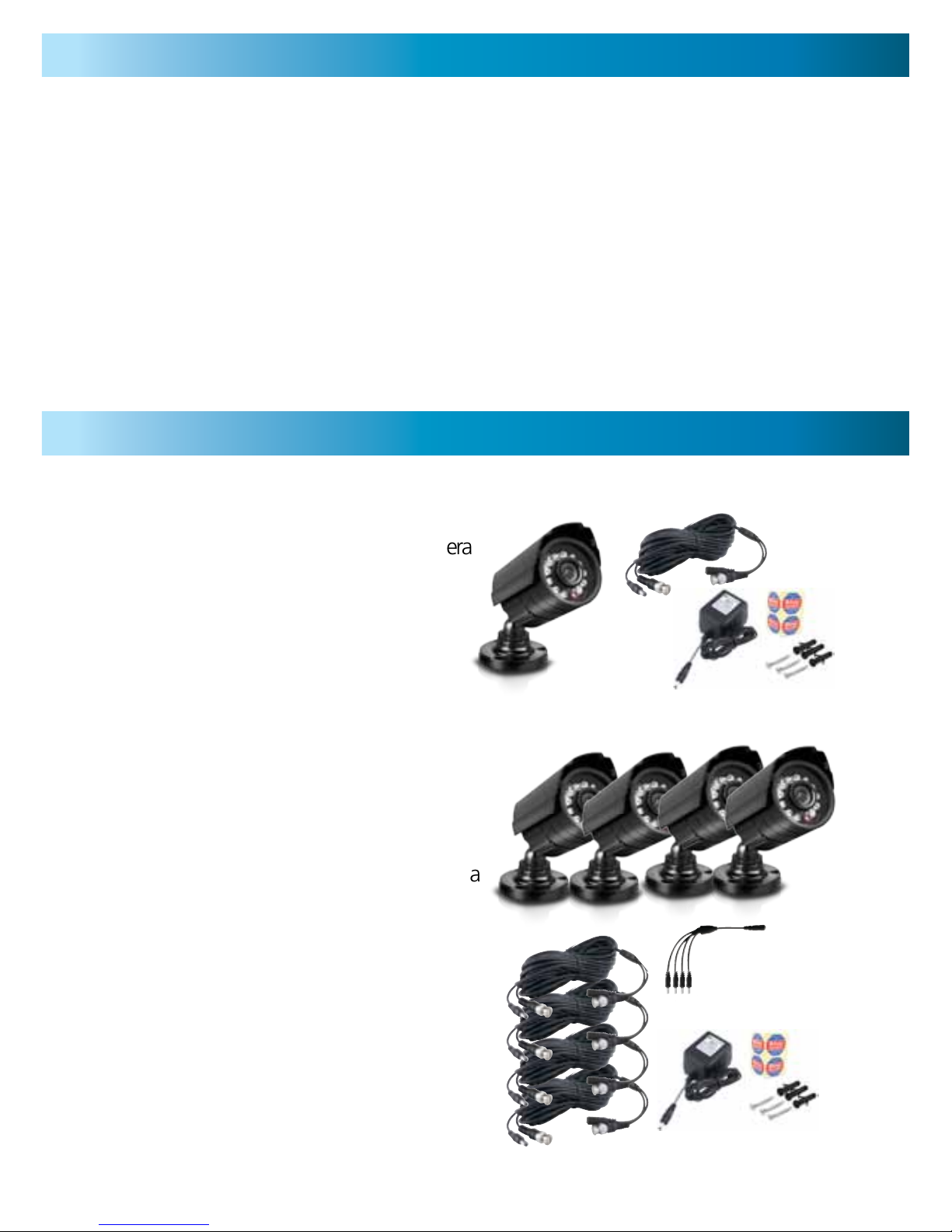
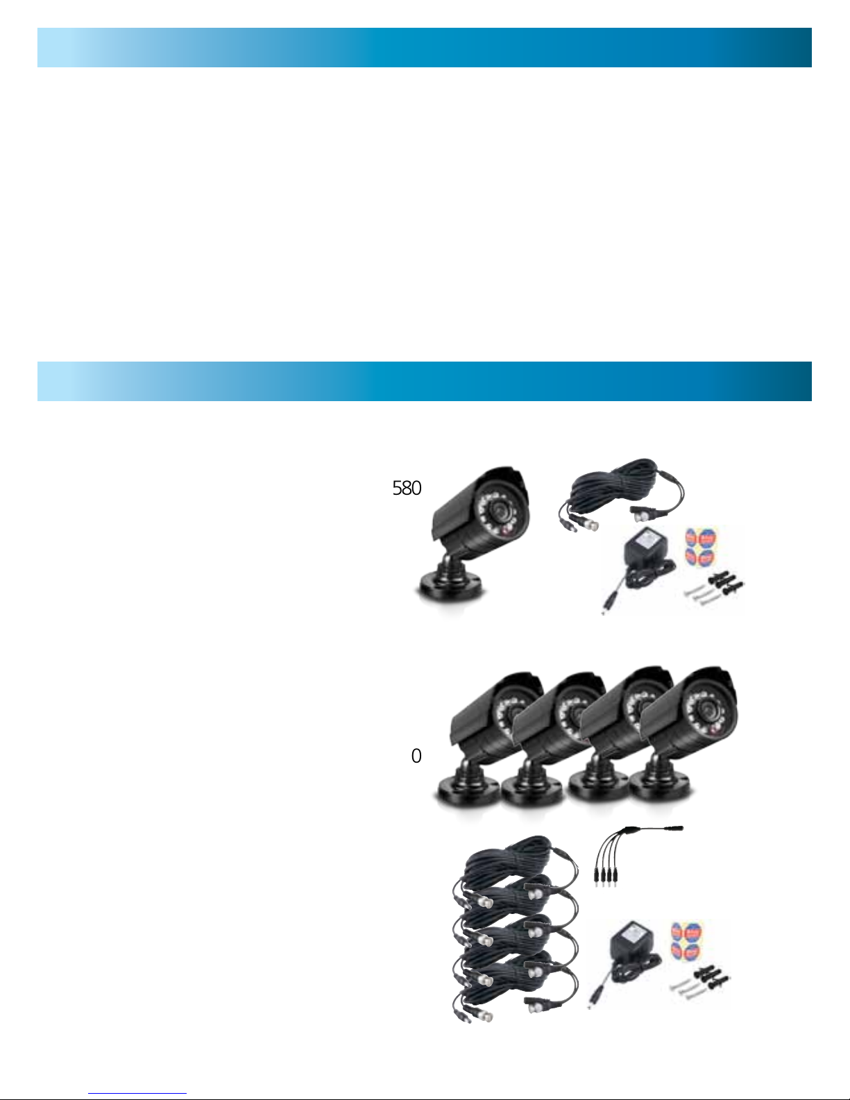
Single Camera Pack
1 x PRO-550/560/580 CCD Security Camera
1 x Extension cable
1 x Screws & wall plugs
1 x Power Adapter
4 x Security Stickers
1 x Operating Instructions
Four Camera Pack
4 x Pro-550/560/580 CCD Security Camera
4 x Extension Cable
4 x Screws and Wall Plugs
1 x Power Splitter
1 x Power Adaptor
4 x Security Stickers
1 x Operating Instructions
Contents
Pack Contents
Page 4
444
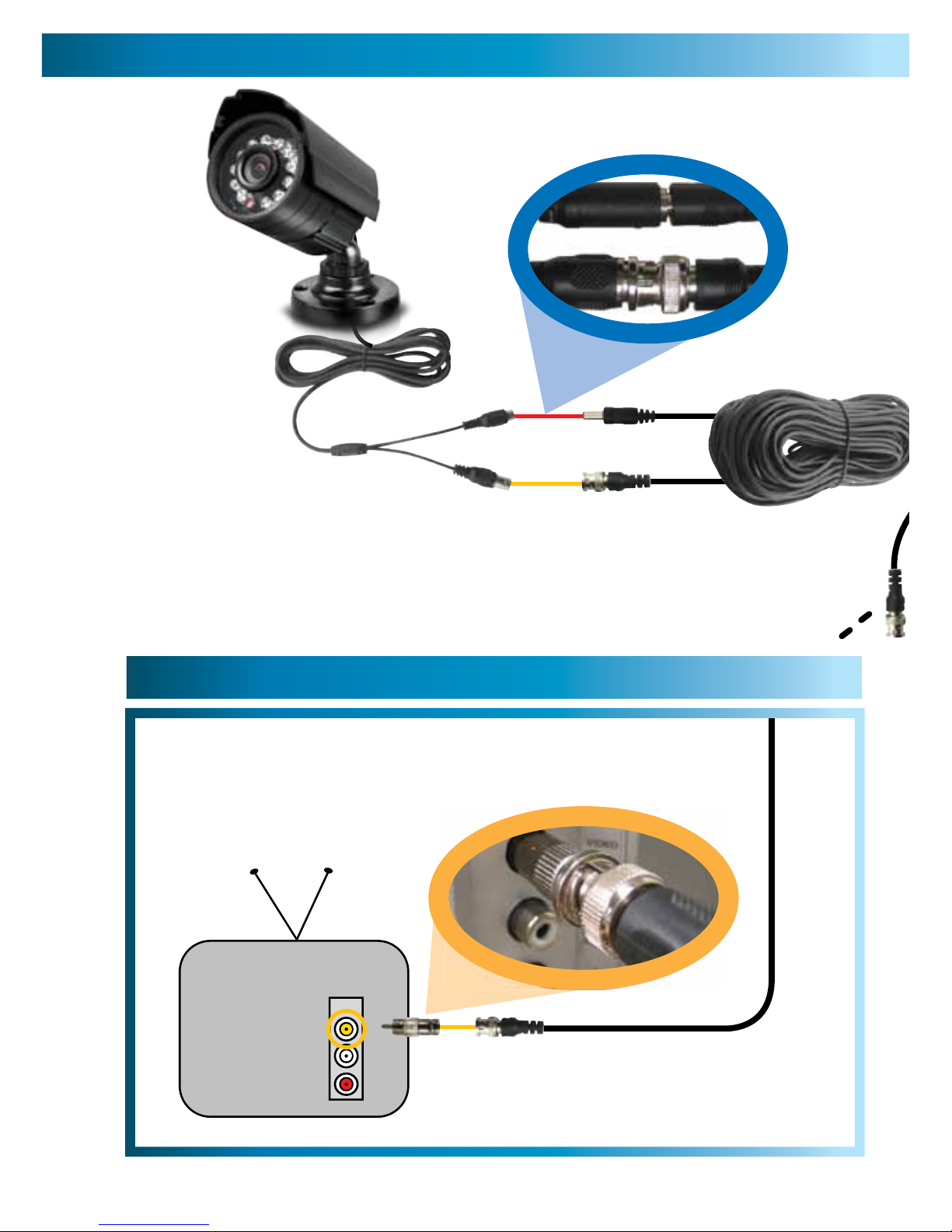
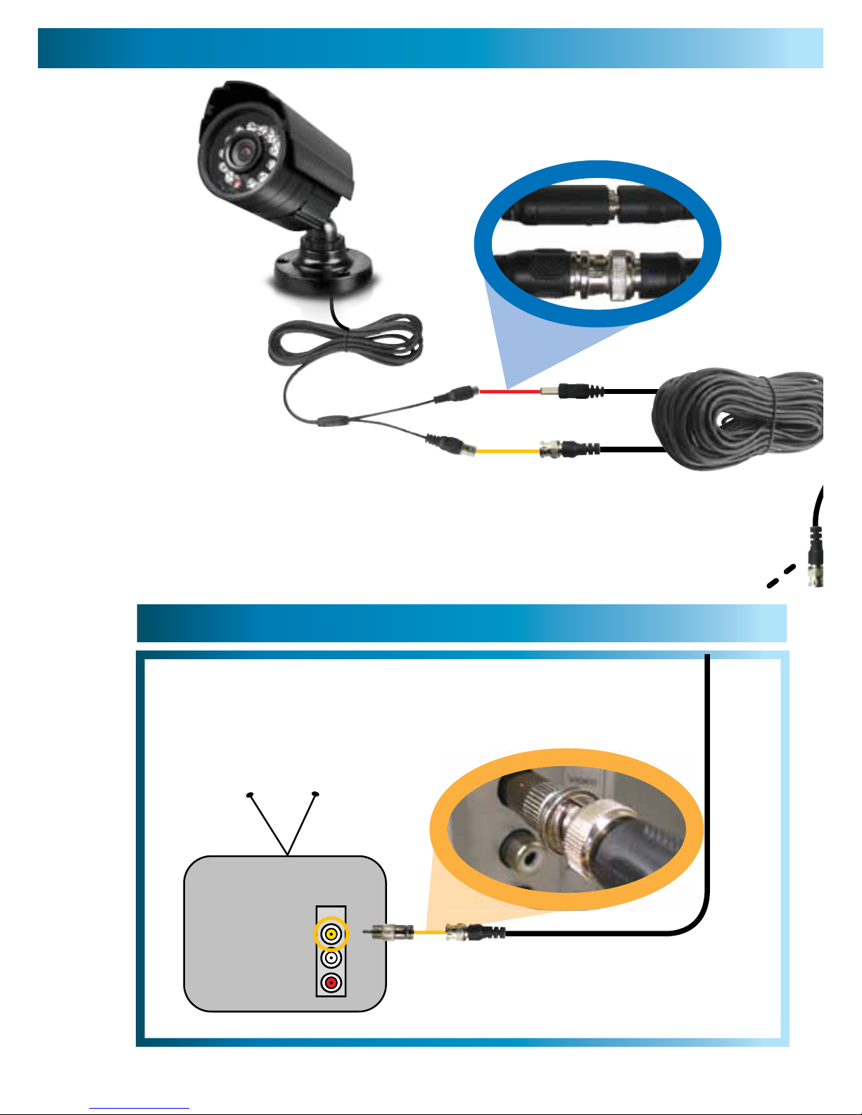
Connect the camera’s DC
and BNC socket cable to the
extension cable’s DC and BNC plugs
1
3A
3B
INPUT
2A. Connecting Directly to TV
2B. Connecting to Your Existing DVR
Connect a BNC to RCA
adapter and connect to video
input on your TV or VCR
2
4
Connection Guide
Page 5

5
Plug in the camera
power adapter into
a wall socket
4
FOR A SINGLE CAMERA
Connect the extension cable’s
DC socket to the DC plug on
the power adapter
3A
FOR 4 CAMERA PACKS
Connect the extension cable’s
DC socket to one of the four
sockets on the power splitter.
Then, plug the single end of the
power splitter to the DC plug
on the power adaptor.
3B
2B. Connecting to Your Existing DVR
Connect the BNC extension
cable to an open channel on
the back of the DVR
2
5
Page 6
6666
Viewing the PRO-550/560/580 on a TV
After connecting the PRO-550/560/580 Camera directly to your TV and powering
it on as described on page 4, tune the TV to the correct input channel.
On your TV’s remote control, the input button is usually labelled as Input, Source,
A/V, Channel 0, AUX etc*.
Viewing and Recording the PRO-550/560/580 on a VCR/DVD Recorder
Connect the PRO-550/560/580 into an available input channel on your VCR/DVDR in the same manner as the TV connection listed on page 4. Turn on your VCR/
DVD recorder and TV as if you were about to play a VCR tape or a DVD.
On your VCR/DVD recorder’s remote control, find the input button with is usually
labelled as L1, L2, Input, Source, A/V, Channel, 0, AUX etc.* Insert a tape and
push record to record the camera.
*Consult the TV or VCR/DVD instruction manual for details about changing input
channels.
The stand on the PRO-550/580
is deceptively adaptable. At first
glance it may appear to limit how
many options you have when
mounting and aiming the camera,
but this is simply untrue. The PRO550/580 stand is almost infinitely
adaptable – it’s like the Rubik’s
Cube of CCTV camera stands!
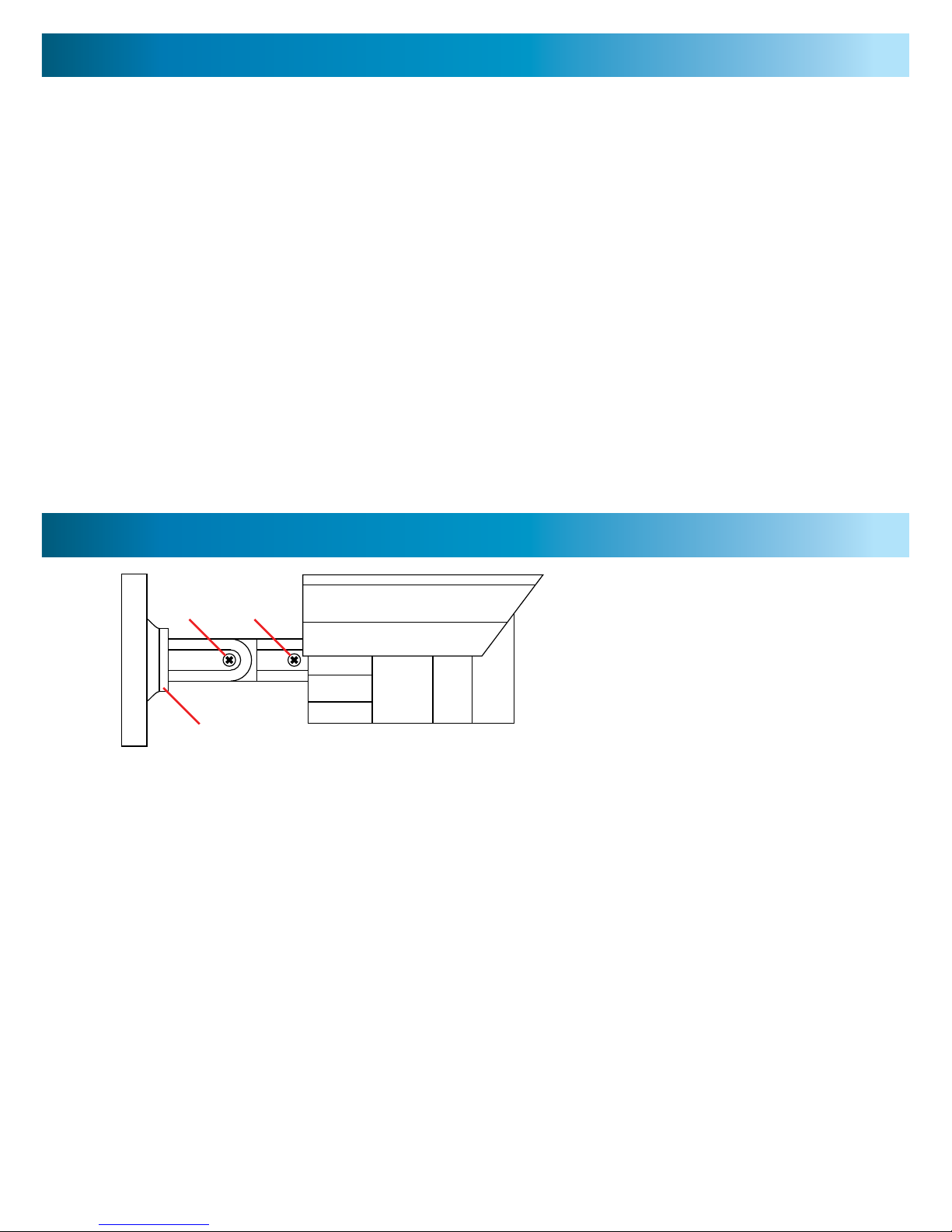
You’ve got three points of articulation. The most obvious is the screw-secured elbow joint in the
centre of the stand (1). This one is pretty obvious and straight forward – loosen the screw, adjust
to the position you want, and then tighten the screw again to secure in place.
The second point of articulation (2) is the radial joint where the neck of the stand attaches
to the base. To adjust this joint, loosen the locking ring by rotating counter-clockwise. Rotate the camera and stand to the position you want then tighten the locking ring. By using
articulation points 1 and 2, you can aim the camera in virtually any direction.
Point 3, located where the camera attaches to the stand, is held in place by one locking
screw. Like point 2, it is a radial joint, allowing you to rotate the camera so that no matter
how points 1 and 2 are configured, the camera can still face upright. Simply loosen the
screw, rotate the camera to the upright position (so that up in your pictures is actually up)
then tighten the screw to lock into place.
Of course, there will always be some outlying cases where the camera and stand simply
won’t fit where you want to mount them. Maybe you have a hanging awning, or a drain
pipe in an inconvenient spot. In these cases, we suggest obtaining a mounting bracket,
which should be available from any good hardware store.
Viewing the Camera on a TV or VCR
Orienting the Camera
1 3
2
Page 7

77
Video
Image Sensor 1/4” CCD
Video Quality 550: 420 TV Lines
560/580: 480 TV Lines
Number of Effective Pixels NTSC: 510 x 492 / PAL: 628 x 582
Minimum Illumination 0 Lux (IR on)
Day/Night mode Colour in lit area / Black & White at night
White Balance Automatic
Signal / Noise Ratio > 50dB
Electronic Shutter 1/60 - 1/100,000 NTSC / 1/50 - 1/100,000 PAL
Gain Control Automatic
Backlight Compensation Yes
Lens 3.6mm
Viewing Angle 62 degrees
Night Vision
Night Vision Distance 550: Up to 45ft/15m
560/580: Up to 65ft / 20m
IR cut filter No
Infra-red LEDs 12
Infra-red wavelength 850nm
Infra-red LED life 10,000 hrs
General
Indoor/Outdoor Both
Operating Power DC 12V
Operating Temperature -4°F ~ 122°F / -20°C~ 50°C
Body Construction Aluminum
Dimensions - PRO-560 Camera & Stand 2.0” x 2.0” x 2.8” / 50mm x 50mm x 70mm
Weight – PRO-560 Camera & Stand 10.5oz / 286g
Dimensions - PRO-550/580 Camera & Stand 3.2” x 2.3” x 2.8” / 58mm x 58mm x 70mm
Weight – PRO-550/580 Camera & Stand 10.5oz / 286g
Problem: I can’t see the camera on my TV.
Solution: Ensure the camera is plugged in and the TV or VCR is tuned to the
correct input channel.
Problem: When I view my camera at night I only see a bright spot and no image.
Solution: Night Vision will reflect when shining through a window. Move the
camera to the other side of the window or another location.
Problem: The BNC Extension Cable will not connect to my TV.
Solution: Connect the BNC to RCA adapter to the end of the Extension Cable
and plug into the TV.
Problem: On my Swann DVR, Video Loss appears where my camera should be.
Solution: Check the Extension cable is securely connected to the camera and
check the connection is secure on the back of the DVR. Also ensure the camera
has power by trying a second power outlet.
Troubleshooting Guide
Technical Specifications
Page 8

888
Vérification FCC :
Note : Cet équipement a été testé et est en conformité avec les limites édictées dans
le paragraphe 15 des Règlementations FCC, relatif aux équipements numériques
de classe B. Ces limites ont été définies dans le but de fournir une protection
raisonnable contre les interférences néfastes dans les installations résidentielles.
Cet équipement génère, utilise et peut irradier des énergies de fréquences radio
et, s’il n’est pas installé dans le respect des instructions fournies, peut provoquer
des interférences auprès des appareils de réception radio-télévisée. Ceci peut être
determine en allumant et éteignant l’appareil. Les methods suivantes peuvent permettre à l’utilisateur de corriger ce problème :
- Réorienter ou déplacer l’antenne réceptrice.
Augmenter l’espace entre l’équipement et le récepteur
- Brancher l’équipement sur une prise ou un circuit différents de celui auquel le
récepteur est connecté.
- Consulter le revendeur ou un technicien radio/télévision expérimenté.
NOTE IMPORTANTE Protection contre les écoutes illégales.
Excepté dans le cadre d’opérations menées dans un cadre légal,
personne n’est autorisé à utiliser, directement ou indirectement, un appareil de
type défini dans le présent cadre
dans un but d’écoute ou d’enregistrement de conversations privées,
à moins que ces dernières aient été autorisées par toutes les parties impliquées.
ATTENTION : Les modifications non approuvées peuvent conduire
à l’annulation du droit de l’utilisateur à utiliser l’équipement.
INSTRUCTIONS DE SECURITE IMPORTANTES
Assurez-vous que le produit est correctement fixé et stable.
Ne pas utiliser si les câbles ou connexions sont exposés.
8
Français
Page 9

9
Avant de commencer 8
Contenu 9
Contenu de l’emballage 9
Guide de connexion 10 - 11
Diffuser la camera sur TV ou VCR 12
Diffuser et enregistrer la camera sur TV ou VCR 12
Astuces & Suggestions 12
Guide de résolution des problèmes 13
Spécifications techniques 13
Informations de garantie 14
Aide / support technique 15
Paquet de caméras avec un seul
1 x Caméra de sécurité PRO-550/560/580 CCD
1 x Vis et prises d’installation murale
1 x Adaptateur alimentation
1 x Rallonge
Instructions
4 x Autocollants de sécurité
Paquets de quatre caméras
4 x Caméra de sécurité PRO-550/560/580 CCD
4 x Vis et prises d’installation murale
4 x Adaptateur alimentation
4 x Rallonge
Instructions
4 x Autocollants de sécurité
Contenu
Contenu de l’emballage
Page 10

101010
1
3A
PACKS POUR 4 CAMERA
Branchez les câbles d'extension
Prise de DC à l'un des quatre
Prises sur le diviseur de puissance.
Ensuite, branchez l'extrémité unique de la
diviseur de puissance à la prise de DC
sur l'adaptateur secteur.
3B
Connexion des prises BNC et
DC de la camera aux prises BNC et
DC de la rallonge.
INPUT
2
Branchez la prise BNC de la rallonge dans la prise BNC de
l’adaptateur RCA vers BNC. Connectez alors la prise RCA à
l’adaptateur RCA vers BNC (qui doit être branché à la
rallonge) de la connextion ENTREE VIDEO située à l’arrière
de votre TV.
2A. Connexion TV directe
2B. Connexion à votre DVR
10
Guide de connexion
Page 11

11
4
3A
PACKS POUR 4 CAMERA
Branchez les câbles d'extension
Prise de DC à l'un des quatre
Prises sur le diviseur de puissance.
Ensuite, branchez l'extrémité unique de la
diviseur de puissance à la prise de DC
sur l'adaptateur secteur.
3B
Branchez
l’adaptateur de
la camera dans
une prise murale.
Branchez la prise DC des
câbles d’extension à la prise
DC de l’adaptateur.
Branchez la prise BNC des rallonges à une prise
BNC (CH1, CH2, CH3 ou CH4) à l’arrière
de votre DVR.
2
2B. Connexion à votre DVR
11
Contenu
Page 12

121212
Avant toute installation permanente, branchez votre camera à votre TV ou VCR en
suivant les consignes de ce Guide de démarrage afin de vous assurer que tous les
éléments fonctionnent correctement.
Si vous éprouvez des difficultés, contactez notre Support Technique. Les informations de contact se trouvent sur la quatrième de couverture de ce guide.
Installez les caméras sufisamment en hauteur pour qu’elles soient hors de portée
Placez les autocollants de sécurité à un emplacement visible, alertant les voleurs
potentiels du fait qu’ils sont filmés.
Achetez un DVR Swann vous permettant d’enregistrer plusieurs caméras en même
temps et de contrôler facilement votre propriété.
Placez les caméras dans les zones de fort passage, par exemple en sorties de portes,
de manière à maximiser la sécurité.
N’utilisez que l’alimentation fournie. Ne modifiez ou ne ocupez pas les câbles.
12
Visualisation de la PRO-550/560/580 sur TV
Après avoir branché directement la caméra PRO-550/560/580 à votre TV et l’avoir
allumé comme décrit en page 4, réglez la TV sur la bonne chaîne d’entrée.
Le bouton d’entrée de la TV est généralement appelée Entrée, Source,
A/V, Chaïne 0, AUX etc.*
Visualisation et enregistrement de la PRO-550/560/580 sur un VCR
Connectez votre PRO-550/560/580 sur une des chaînes d’entrée disponibles de
votre VCR de la même manière que pour le raccordement à une TV 5voir p 4°.
Connectez votre VCR et votre TV comme si vous souhaitiez lire une cassette. Sur
la télécommande de votre VCR, localisez le bouton d’entrée, généralement appelé L1, L2, Entréee, Source, A/V, Chaîne 0, AUX etc.*
Insérez une cassette et appuyez sur enregoistrement.
* Consultez le manuel d’installation de votre TV ou de votre VCR pour plus de
détails.
Astuces & Suggestions
Diffuser la camera sur TV ou VCR
Page 13

1313
Vidéo
Capteur d’image : 1/4” CCD
Qualité video : 550: 420 TV Lignes
560/580: 480 TV Lignes
Nombre de pixels effectifs : NTSC: 510 x 492 / PAL: 628 x 582
Illumination minimale : 0 Lux (IR on)
Mode jour/nuit : Couleur dans les zones éclairées, Noir et Blanc en mode Nuit.
Balance des blancs : Automatique
Ratio bruit / signal > 50dB
Obturaton électronique 1/60 - 1/100,000 NTSC / 1/50 - 1/100,000 PAL
Contrôle du gain Automatique
Compensation contre-jour Oui
Lentille : 3.6mm
Angle de vue : 62 degrés
Vision nocturne
Distance vision de nuit : Jusqu`à 20 m / 65 pieds
Filtre IR : Non
LED infrarouges : 12
Longueur d’onde infrarouge : 850nm
Durée de vie LED infrarouge : 10,000 hrs
Général
Intérieur/Extérieur Les deux
Alimentation : 12V DC
Température de fonctionnement : -4°F ~ 122°F / -20°C~ 50°C
Composition de la structure Aluminium
Dimensions – Caméra et structure 560 : 2.0” x 2.0” x 2.8” / 50mm x 50mm x 70mm
Poids – caméra & structure 560 : 10.5oz / 286g
Dimensions – Caméra et structure 550/580 : 3.2” x 2.3” x 2.8” / 58mm x 58mm x 70mm
Poids – caméra & structure 550/580 : 1005oz / 286g
Problème : Je ne parviens pas à voir la caméra sur ma TV.
Solution : Assurez-vous que la caméra est bien branchée et que la TV ou le VCR
sont positionnés sur la bonne chaîne.
Problème :
De nuit, ma caméra ne diffuse qu’une grande tache claire, aucune image.
Solution : Les ondes infraroues utilisées pour la vision nocturne peuvent être
reflétées par les fenêtres ou les miroirs. Déplacez votre caméra de l’autre côté de
la fenêtre.
Problème : Le câble d’extension BNC ne peut pas être branché sur ma TV
Solution : Connectez l’extrémité BNC du câble d’extension à l’adaptateur RCA.
Problème : Sur mon DVR Swann, le message Perte Vidéo apparaît là où devrait
se trouver ma caméra.
Solution : Vérifiez que la rallonge est correctement connectée à la camera et
que les connexions situées à l’arrière du DVR sont sécurisées. Assurez-vous
également que la caméra est alimentée en essayant une seconde prise électrique.
Spécifications techniques
Guide de résolution des problèmes
Page 14

141414
Swann Communications garantit ce produit contre tout défaut de fabrication et contre
tout défaut matériel pour une période de un (1) an à compter de la date d’achat.
Vous devez présenter votre reçu comme preuve de la date d’achat pour valider votre
garantie. Toute unité défectueuse sera réparée gratuitement (pièces et main d’œuvre)
ou remplacée, à la discrétion de Swann. L’utilisateur final est responsable de tous les frais
de port qu’implique l’envoi du produit au centre de réparation de Swann. L’utilisateur
est responsable de tous les frais de port si l’envoi doit être effectué en provenance ou
à destination de tout pays hors du pays d’origine.
La présente garantie ne couvre pas tous les dégâts consécutifs à un mauvais usage du
produit. Tous les coûts associés à la prise en charge ce produit ou à son usage sont
dans ce cas de la responsabilité de l’utilisateur. Cette garantie s’applique à l’acheteur
original du produit et ne peut être transférée à une tierce partie. Toute modification
non autorisée de tout élément, u toute preuve de mauvaise utilisation de cet appareil
annulera l’ensemble des garanties.
Certains pays n’autorisent pas les limitations de certaines exclusions de la présente
garantie. Les réglementations et lois locales priment.
Information sur la Garantie
Swann Communications USA Inc.
12636 Clark Street
Santa Fe Springs CA 90670
USA
Swann Communications
Unit 13, 331 Ingles Street,
Port Melbourne Vic 3207
Swann Communications LTD.
Stag Gates House
63/64 The Avenue
SO171XS
United Kingdom
Page 15

15
© Swann Communications 2011
Sans frais États-Unis:
1-800-627-2799
(Dim, 14h00- 22h00 Heure du Pacifique)
(Lun-Jeu, 6h00-10h00 Heure du Pacifique)
(Ven, 6h00-14h00 Heure du Pacifique)
Échanges et Réparations États-Unis:
1-800-627-2799 (option 1)
(Lun-Ven, 9h00-17h00 Heure du Pacifique)
Il peut y avoir de légères variations saisonnières concernant les heures
UK
0203 027 0979
Assistance technique disponible en anglais seulement.
Félicitation pour votre achat. Si à n’importe quel moment ce produit ne fonctionne
pas quand vous le branchez pour la première fois ou si vous vous rencontrez un
problème, ne le rapportez pas au magasin !
Aide / Support Technique
Page 16

161616
Verificación de la FCC:
NOTA: Este equipo ha sido probado y se encontró que cumple con los límites para
aparatos digitales Clase B, de acuerdo con la parte 15 del reglamento de la FCC.
Estos límites están diseñados para proveer protección razonable contra interferencia dañina en una instalación residencial. Este equipo genera, usa y puede irradiar
energía de radiofrecuencia y, si no se instala y se usa de acuerdo con las instrucciones, puede causar interferencia dañina en la recepción de radio o televisión, lo
cual se puede determinar encendiendo y apagando el equipo, se alienta al usuario
intentar corregir la interferencia mediante una o más de las siguientes medidas:
• Reoriente o cambia de ubicación la antena receptora.
• Incremente la separación entre el equipo y el receptor.
• Conecte el equipo a una toma en un circuito diferente al que está conectado el
receptor.
• Consulte al distribuidor o a un técnico en radio/televisión con experiencia por
NOTA IMPORTANTE: Prohibición contra indiscreciones
Excepto par alas operaciones conducidas por oficiales de aplicación de la ley bajo
una autoridad de ley, ninguna persona deberá usar, ya sea directa o indirectamente,
un aparato usado de acuerdo con las disposiciones de esta Parte con el propósito
de escuchar o grabar las conversaciones privadas de otras personas a menos que
tal uso esté autorizado por todas las partes participantes en la conversación.
ADVERTENCIA: Las modificaciones no aprobadas por la parte responsable de su
cumplimiento puede cancelar la autoridad del usuario para usar el equipo.
INSTRUCCIONES IMPORTANTES DE SEGURIDAD:
• Asegúrese que el producto se je correctamente y esté estable si es sujetado en
su lugar.
• No use si los cables y las terminales están expuestas.
16
Español
Page 17
17
Antes de que Comience 16
Índice 17
Contenido del Paquete 17
Guía de Conexión 18 - 19
Viendo la Cámara en una TV o VCR 20
Viendo y grabando en una TV o VCR 20
Consejos y Sugerencias 20
Guía para Resolver Problemas 21
Especificaciones Técnicas 21
Información de Garantía 22
Detalles de Soporte Técnico 23
De paquetes de una cámara
1 x Cámara de Seguridad PRO-550/560/580
1 x Tornillos y enchufes de pared
1 x Adaptador de Corriente
1 x Cable de extensión
4 x Calcomanías de Seguridad
Instrucciones de Uso
Paquete de cuatro cámaras de
4 x Cámara de Seguridad PRO-550/560/580
4 x Tornillos y enchufes de pared
4 x Adaptador de Corriente
4 x Cable de extensión
4 x Calcomanías de Seguridad
Instrucciones de Uso
Índice
Contenido del Paquete
Page 18
181818
1
3A
CÁMARA DE 4 paquetes de
Conecte los cables de extensión de
To ma de CC a una de las cuatro
tomas de corriente en el divisor de potencia.
A continuación, conecte el único fin de la
separador de alimentación a la clavija de cc
en el adaptador de corriente.
3B
2A. Conectando Directamente a la TV
2B. Conectando su DVR Existente
Conecte el cable de toma DC y
BNC a los enchufes DC y BNC del
cable de de extensión.
Conecte el enchufe BNC en el cable de extensión en la toma
BNC en el adaptador RCA a BNC. Luego conecte el enchufe
RCA en el adaptador RCA a BNC (que debe conectarse al
cable de extensión) a la conexión de ENTRADA DE VIDEO
en la parte posterior de su TV.
INPUT
2
18
Guía de Conexión
Page 19

19
4
3A
CÁMARA DE 4 paquetes de
Conecte los cables de extensión de
To ma de CC a una de las cuatro
tomas de corriente en el divisor de potencia.
A continuación, conecte el único fin de la
separador de alimentación a la clavija de cc
en el adaptador de corriente.
3B
Conecte el
adaptador de
corriente de la
cámara a la
toma de la
pared.
2B. Conectando su DVR Existente
Conecte la toma DC de los
cables de extensión al enchufe
DC en el adaptador de corriente.
Conecte el enchufe BNC de los cables de
extensión a la toma BNC (CH1, CH2, CH3
o CH4) en la parte posterior del DVR.
2
19
Page 20

202020
Antes de hacer una instalación permanente, conecte la cámara a su televisión o
VCR usando la Guía de Inicio Rápido para asegurarse que todos los componentes
en el paquete estén funcionando correctamente.
Si tiene problemas conectando el producto contacte a nuestro equipo de Soporte
Técnico. Los detalles de contacto están en la página de la cubierta posterior de
esta guía.
Instale las cámaras suficientemente alto para que estén fuera de alcance para evitar alteraciones.
Coloque las Calcomanías de Seguridad en una ubicación visible para alertar a potenciales ladrones de que están siendo monitoreados.
Compre un DVR Swann para grabar múltiples cámaras simultáneamente y monitorear fácilmente su propiedad.
Coloque las cámaras en áreas de alto tránsito tales como puertas para maximizar
la seguridad.
Use solo el Suministro de Corriente incluido y no modifique o corte alambres.
20
Viendo la PRO-550/560/580 en una TV
Después de conectar la Cámara PRO-550/560/580 directamente a su televisión y
conectándola a la corriente como se describe en la página 4, sintonice la televisión al canal de entrada correcto.
En el control remoto de su televisión, el botón de entrada usualmente se nombra
como Input, Source, A/V, Channel 0, AUX, etc.*
Viendo y Grabando la PRO-550/560/580 en una VCR
Conecte la PRO-550/560/580 a un canal de entrada disponible en su VCR de la
misma forma como la conexión a televisión en la página 4. Encienda su VCR y
televisión como si fuera a reproducir una cinta de video.
En el control remoto de su VCR, busque el botón de entrada que usualmente se
llama L1, L2, Input, Source, A/V, Channel 0, AUX, etc.* Inserte una cinta y presione grabar para grabar la cámara.
*Consulte el manual de instrucciones de la televisión o VCR para detalles sobre
cómo cambiar canales de entrada.
Viendo la Cámara en una TV o VCR
Consejos y Sugerencias
Page 21

2121
Video
Sensor de Imagen CCD de 1/4”
Calidad de Video 550: 420 Líneas de Televisión
560/580: 480 Líneas de Televisión
Número Efectivo de Pixeles NTSC: 510 x 492 / PAL: 628 x 582
Iluminación Mínima 0 Lux (IR encendido)
Modo Día/Noche Color en áreas iluminadas / Blanco y Nego de noche
Balance de Blancos Automático
Relación Señal / Ruido > 50dB
Obturador Electrónico 1/60 - 1/100,000 NTSC / 1/50 - 1/100,000 PAL
Control de Ganancia Automático
Compensación por Luz de Fondo Sí
Lente 3.6mm
Ángulo de Visión 62 grados
Visión Nocturna
Distancia con Visión Nocturna 550: Hasta 45 pies / 15m
560/580: Hasta 65 pies / 20m
Filtro de Corte de IR No
LEDs Infrarrojos 12
Longitud de Onda de Infrarrojo 850nm
Vida útil del LED infrarrojo 10,000 hrs
General
Interiores/Exteriores Ambos
Energía Operativa DC 12V
Temperatura Operativa -4°F ~ 122°F / -20°C~ 50°C
Construcción de la Cubierta Aluminio
Dimensiones – Cámara y Soporte PRO-560 2.0” x 2.0” x 2.8” / 50mm x 50mm x 70mm
Peso – Cámara y Soporte PRO-560 10.5oz / 286g
Dimensiones – Cámara y Soporte PRO-550/580 3.2” x 2.3” x 2.8” / 58mm x 58mm x 70mm
Peso – Cámara y Soporte PRO-550/580 10.5oz / 286g
Problema: No puedo ver la cámara en mi televisión.
Solución: Asegúrese de que la cámara esté conectada y que la televisión o VCR
esté sintonizados al canal de entrada correcto.
Problema: Cuando veo mi cámara en la noche solo veo una mancha brillante y
nada de imagen.
Solución: La Visión Nocturna se reflejará cuando brille a través de una ventana.
Mueva la cámara al otro lado de la ventana o a otra ubicación.
Problema: El Cable de Extensión BNC no se conecta a mi televisión.
Solución: Conecte el adaptador BNC a RCA al extreme del Cable de Extensión y
conecte a la televisión.
Problema: En mi DVR Swann, aparece Pérdida de Video donde debería estar la cámara.
Solución: Revise que el cable de extensión esté conectado completamente a la
cámara y revise que la conexión sea correcta en la parte posterior del DVR. Tam-
bién asegúrese de que la cámara tenga corriente probando una segunda toma de
corriente.
Guía para Resolver Problemas
Especificaciones Técnicas
Page 22

222222
Información sobre la garantía
Swann Communications garantiza este producto por defectos de fabricación y material,
por un período de un (1) año a partir de la fecha original de compra. Usted deberá
presentar su recibo como prueba de la fecha de compra para validar la garantía.
Cualquier unidad que se compruebe defectuosa durante el período antes citado será
reparada sin cobrar los repuestos o la mano de obra, o será sustituida, a discreción
exclusiva de Swann. La reparación o sustitución se garantizará por noventa días o por el
período que falte de la garantía original de un año, el que resulte más largo de los dos.
El usuario final asume los costos de fletes incurrido para enviar el producto a los centros
de reparación de Swann. El usuario final se responsabiliza de los costos de envío en que
incurran cuando envía desde y hacia cualquier país distinto al país de origen. La garantía
no cubre daños accidentales, circunstanciales o que resulten del uso o la imposibilidad
de utilizar este producto. Cualquier costo asociado con la adaptación o remoción
de este producto por parte de un vendedor o de otra persona, o cualquier costo
asociado con el uso del mismo son responsabilidad del usuario final. Esta garantía aplica
exclusivamente al comprador original del producto, y no es transferible a terceros.
Si el usuario final o un tercero hacen modificaciones no autorizadas a cualquier
componente o si hay evidencia de mal uso o abuso del dispositivo, se anularán todas
las garantías.
Swann Communications USA Inc.
12636 Clark Street
Santa Fe Springs CA 90670
USA
Swann Communications
Unit 13, 331 Ingles Street,
Port Melbourne Vic 3207
Swann Communications LTD.
Stag Gates House
63/64 The Avenue
SO171XS
United Kingdom
Page 23

23
© Swann Communications 2011
Centro de asistencia técnica
Soporte Técnico Swann
Todos los países Correo Electrónico: tech@swannsecurity.com
Atención Telefónica al Usuario
ESTADOS UNIDOS Sin costo
1800-627-2799
(Dom, 2pm-10pm HP EE.UU.Lun-Juev, 6am-10pm, HP EE.UU.
Viern, 6am-2pm HP EE.UU.)
ESTADOS UNIDOS Cambios & Devoluciones
1800-627-2799 (Opción 1)
(Lun-Viern, 9am-5pm HP EE.UU.)
UK
0203 027 0979
Asistencia técnica disponible en Inglés solamente.
Page 24

242424
© Swann Communications 2011
Warranty Information
Helpdesk / Technical Support Details
Swann Technical Support
All Countries E-mail: tech@swannsecurity.com
Telephone Helpdesk
See http://www.worldtimeserver.com for information on time zones and the current time in
Melbourne, Australia compared to your local time.
USA toll free
1-800-627-2799
(Su, 2pm-10pm US PT)
(M-Th, 6am-10pm US PT)
(F 6am-2pm US PT)
USA Exchange & Repairs
1-800-627-2799 (Option 1)
(M-F, 9am-5pm US PT)
AUSTRALIA toll free
1300 138 324
(M 9am-5pm AUS ET)
(Tu-F 1am-5pm AUS ET)
(Sa 1am-9am AUS ET)
NEW ZEALAND toll free
0800 479 266
UK
0203 027 0979
Swann Communications warrants this product against defects in workmanship and material for a period of
one (1) year from it’s original purchase date. You must present your receipt as proof of date of purchase for
warranty validation. Any unit which proves defective during the stated period will be repaired without charge
for parts or labour or replaced at the sole discretion of Swann. The end user is responsible for all freight
charges incurred to send the product to Swann’s repair centres. The end user is responsible for all shipping
costs incurred when shipping from and to any country other than the country of origin.
The warranty does not cover any incidental, accidental or consequential damages arising from the use of
or the inability to use this product. Any costs associated with the fitting or removal of this product by a
tradesman or other person or any other costs associated with its use are the responsibility of the end user.
This warranty applies to the original purchaser of the product only and is not transferable to any third party.
Unauthorized end user or third party modifications to any component or evidence of misuse or abuse of the
device will render all warranties void.
By law some countries do not allow limitations on certain exclusions in this warranty. Where applicable by
local laws, regulations and legal rights will take precedence.
Swann Communications USA Inc.
12636 Clark Street
Santa Fe Springs CA 90670
USA
Swann Communications
Unit 13, 331 Ingles Street,
Port Melbourne Vic 3207
Swann Communications LTD.
Stag Gates House
63/64 The Avenue
SO171XS
United Kingdom
FCC Verification
This equipment has been tested and found to comply with the limits for Class B digital device, pursuant to part 15 of
the FCC Rules. These limits are designed to provide reasonable protection against harmful interference in a residential
installation. This equipment generates, uses and can radiate radio frequency energy and, if not installed and used
in accordance with the instructions, may cause harmful interference to radio or television reception, which can be
determined by turning the equipment off and on, the user is encouraged to try to correct the interference by one or
more of the following measures:
• Reorient or relocate the receiving antenna
• Increase the separation between the equipment and the receiver
• Connect the equipment into an outlet on a circuit different from that to which the receiver is connected
• Consult the dealer or an experienced radio/TV technician for help
WARNING: Modifications not approved by the party responsible for compliance could void user’s authority to
operate the equipment.
 Loading...