

Page 1
5
6
M1080ZLB120416CAM16E | © Swann 2016
FCC Verification
This equipment has been tested and found to comply with the limits for Class B digital device, pursuant to part 15 of the FCC Rules. These limits are designed to provide reasonable protection against
harmful interference in a residential installation. This equipment generates, uses and can radiate radio
frequency energy and, if not installed and used in accordance with the instructions, may cause harmful
interference to radio or television reception, which can be determined by turning the equipment off and
on, the user is encouraged to try to correct the interference by one or more of the following measures:
• Reorient or relocate the receiving antenna
• Increase the separation between the equipment and the receiver
• Connect the equipment into an outlet on a circuit different from that to which the receiver is connected
• Consult the dealer or an experienced radio/TV technician for help
These devices comply with part 15 of the FCC Rules. Operation is subject to the following two conditions:
1. These devices may not cause harmful interference.
2. These devices must accept any interference received, including interference that may cause undesired operation.
HD Zoom
Security Camera
1080p HD Bullet Camera
EN
INSTRUCTION MANUAL
Security Made Smarter
The camera can be mounted onto a flat surface using screws. The surface must have
sufficient strength to hold the camera.
• Position the camera in the location you want to mount it, and mark the screw holes
on the surface to position the screws. Then, using appropriate screws for the surface
you’re fixing the camera to, secure the camera into place.
• If you’re mounting to a wooden surface, then screw the camera directly to the surface.
• If you’re mounting to a masonry surface (bricks, concrete or similar) then you’ll need to
use the included wall plugs.
Aiming the camera
You can use the included allen key to adjust the camera angle.
• To adjust the orientation, loosen the screw indicated by 1. This
enables you to rotate the camera so no matter what direction it is
facing, your images will be the right way up.
• To tilt up and down, loosen the indicated by 2.
• To pan left and right, loosen the screw indicated by 3.
Be sure to tighten the screws back securely to lock the camera’s position
in place after you finish adjusting the camera angle.
2
1
3
Helpdesk/Technical Support
Telephone Helpdesk
USA Toll Free 1-800-627-2799
USA Parts & Warranty 1-800-627-2799
(M-F, 9am-5pm US PT)
AUSTRALIA 1800 788 210
NEW ZEALAND Toll Free 0800 479 266
UK 0808 168 9031
Limited Warranty Terms & Conditions
Swann Communications warrants this product against defects in workmanship and material for a period of one (1) year from its original
purchase date. You must present your receipt as proof of date of purchase for warranty validation. Any unit which proves defective during
the stated period will be repaired without charge for parts or labour or replaced at the sole discretion of Swann. The end user is responsible
for all freight charges incurred to send the product to Swann’s repair centres. The end user is responsible for all shipping costs incurred
when shipping from and to any country other than the country of origin.
The warranty does not cover any incidental, accidental or consequential damages arising from the use of or the inability to use this product.
Any costs associated with the fitting or removal of this product by a tradesman or other person or any other costs associated with its use
are the responsibility of the end user. This warranty applies to the original purchaser of the product only and is not transferable to any
third party. Unauthorized end user or third party modifications to any component or evidence of misuse or abuse of the device will render
all warranties void.
By law some countries do not allow limitations on certain exclusions in this warranty. Where applicable by local laws, regulations and
legal rights will take precedence.
For Australia: Our goods come with guarantees which cannot be excluded under Australian Consumer Law. You are entitled to a
replacement or refund for a major failure and for compensation for any other reasonably foreseeable loss or damage. You are also entitled
to have the goods repaired or replaced if the goods fail to be of acceptable quality and the failure does not amount to major failure.
Technical Support E-mail: tech@swann.com
Mounting the camera
Page 2
1 2 3 4
Congratulatio ns on your purchase of t his HD
Zoom Security Camera.
• Use the On-Screen D isplay (OSD) con troller
& built-in softw are to customi ze the camer a
settings includi ng color, brightness & wide
dynamic range fo r the best video qua lity
every time.
• This camera can b e used in combination
with other analog su rveillance technolog y
including AHD, T VI, CVI from Sw ann &
other brands. It ’s the perfect addi tion if you
already have a re cording solution (DVR) &
need extra cam eras.
• The camera joy stick is used to set the
signal modes for the c amera.
• The zoom function is controlled by your
DVR’s PTZ contro ls. Please sear ch the
Support Information at support.swann.
com (search for ‘1080 ZLB’) for instruc tions
on controlling this feature.
Important note: All jurisdict ions have specific
laws and regula tions relating to the u se of
cameras. Befor e using any camera f or any
purpose, it is the bu yer’s responsibil ity to be
aware of all applic able laws and reg ulations
that prohibit or limi t the use of cameras and to
comply with the appl icable law s and regulati ons.
Warning: Modifications not approved by the party
responsible for compliance could void user’s
authority to operate the equipment.
Important safety instructions
• Make sure product is fixed correctly and
stable if fastened in place.
• Do not operate if wires and terminals are
exposed.
Introduction Choosing a location for your Camera
This camera has an on-screen configuration menu
to configure various image settings as they apply
to the camera and the scene that you wish to view.
• You should endeavor to set the camera up
close to the area you wish to view before you
install the camera so that you have access to
the joystick and can adjust the image settings.
• What you want to monitor and where you’ll
get the best view of it.
• How you’re going to connect the camera to
your monitoring system; you should plan the
route from the recorder to each camera.
• How to keep the camera out of harm’s way.
It’s recommended to mount your cameras in
an elevated position to prevent easy access.
• Place your camera as close to the area of
interest as practicable. The best position
is from about 3-4m (9-13ft) above looking
slightly down.
• Although the sky looks nice when you look at
the live view from your camera, it is an unlikely
direction for an offender to approach from.
Keep the camera pointed down away from the
sky or ceiling. This will also minimize glare
from lighting affecting the image.
• Think about the most likely way a potential
offender may approach your home and
position your cameras to give you the best
coverage of these areas.
• The camera’s casing is resistant to water,
different weather conditions and tampering.
However, the cable and connectors are
vulnerable and require protection.
Positioning the cables
• When running the cable, try to avoid bending
it at sharp angles
• Avoid positioning the cable near live electrical
wiring as electrical current generates a
magnetic field which can interfere with the
signal from your camera.
PTZ
7
5 3
1
8
6 4
2
eSATA
HDMI LAN & USB B A
DC 12V
IN
VGAVIDEO IN AUDIO OUT
AUDIO IN
Connection GuideConnection Guide
Configuring PTZ settings
The DVR’s default PTZ settings should allow you to use the
camera without any additional configuration. But to be sure,
check that the settings in your DVR’s Device PTZ menu match
the ones shown here.
For more information on configuring PTZ settings, consult your
DVR user manual.
Camera No.: Channel1
Baud Rate: 9600
Data Bit: 8
Stop Bit: 1
Parity: None
Flow Ctrl: None
PTZ Protocol: Pelco-D
Address(0-255): 1
OSD Joystick
1
2
3
4
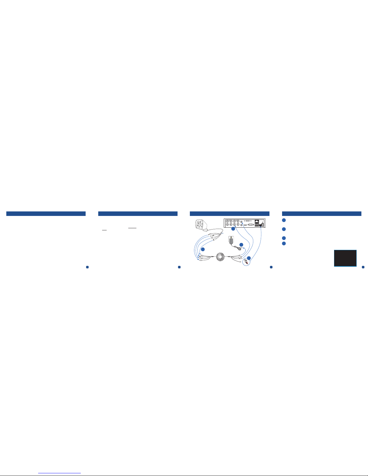
Connect the camera’s RS485, Video, Audio and Power connectors to the Video, Audio & Power
cable. Make sure to twist and lock video connectors for a secure connection. Screw in the
RS485 connectors making sure that the red and black line up with the positive and negative
icons on the RS485 connection (check the tag on the camera cable).
Remove the green RS485 terminal block from the PTZ port on the DVR, and then using a
flat-head screwdriver, attach the pair of PTZ wires on the other end of the Video & Power
cable (RED to + / A socket, BLACK to - / B socket) to the RS485 terminal block. When wiring
connections are complete, plug the RS485 terminal block back into the PTZ port on the DVR.
Connect the camera to a video input on the DVR. For ease in configuring the RS485 settings,
we suggest connecting it to channel 1 initially.
Connect the camera to the power adapter. After the camera is powered on, if you do not see an
image or the image is poor, please check that you are using the correct video output signal for
your DVR. Hold for 2 seconds; Up for A nalog, Left for A HD, Right for TVI a nd Down for CVI.
1
2
3
4
 Loading...