

Page 1
1
DVR Quick Start Guide
• Getting to know your DVR
• What does this mean?
• Connect your Cameras
• Connect the DVR to your Home Network
• Connect the Mouse
• Connect the DVR to your HDTV
• Connect the DVR to your Monitor (optional)
• Connect the Power Adapter
QH8_8050V2280515E | © Swann 2015
Welcome! Lets get started.
READ ME
FIRST
Page 2
4
Congratulations on the purchase of your Swann DVR. This quick start guide will assist you on getting your DVR up and
running as soon as possible. We recommend that you connect everything and give it a try before you do a permanent
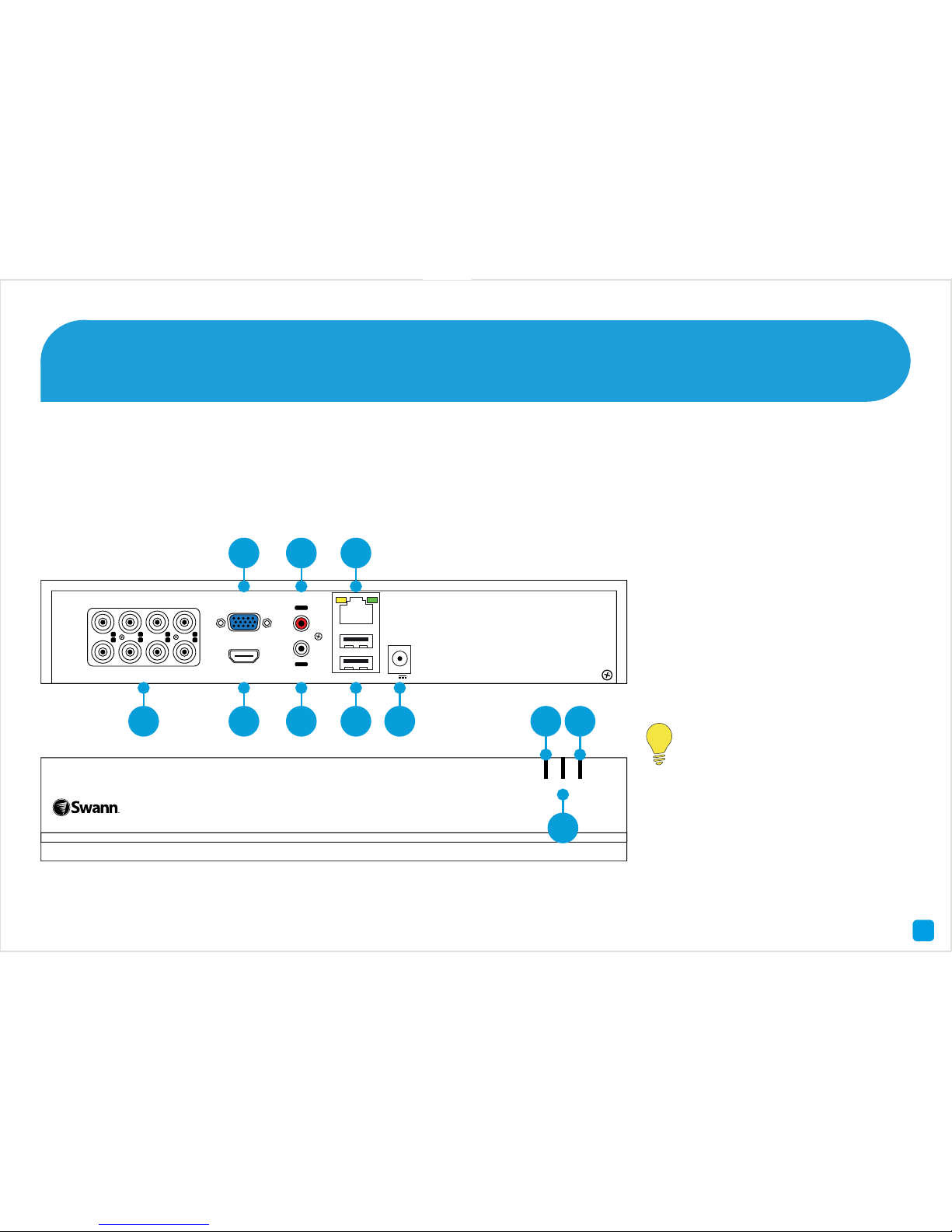
installation, to make sure nothing was damaged during shipping. On the other side is a detailed connection map which
illustrates the various connections on the DVR.
1) Video In
2) VGA
3) HDMI
4) Audio In
5) Audio Out
6) LAN
7) USB
8) Power Input
9) PWR LED
10) HDD LED
11) NET LED
Getting to know your DVR
2
Look out for the light bulb icon,
as this provides information on
the operation of your DVR.
1234567
8
ININININ
OUT
VIDEO IN HDMI
VGA
AUDIO LAN & USB
12V
1 3 5 7 8
2 4 6
PWR HDD NET
8 Channel HD Digital Video Recorder
9
10
11
Page 3
7
Here are explanations for the various connections and
lights on the DVR -
1) Video In - Connect the included cameras here.
2) VGA (optional) - If you have a digital TV or a monitor
with a VGA connection, connect this to an available input.
3) HDMI - Connect this to your digital TV with a HDMI input
(HDMI cable included).
4) Audio In - For connecting a microphone or some other
audio device.
5) Audio Out - For connecting speakers.
6) LAN - Connect this to your home network so your DVR
can connect to the Internet.
7) USB - Connect the mouse here. Also able to connect
a storage device such as a USB flash drive to backup
recorded events or to perform a firmware upgrade.
8) Power Input - This is where you connect the power
adapter.
9) PWR LED - This indicates the DVR has power.
10) HDD LED - This will flash when the hard drive is
working.
11) NET LED - This will flash when there is network activity.
What does this mean?
3
Page 4
24
Connect your Cameras 1
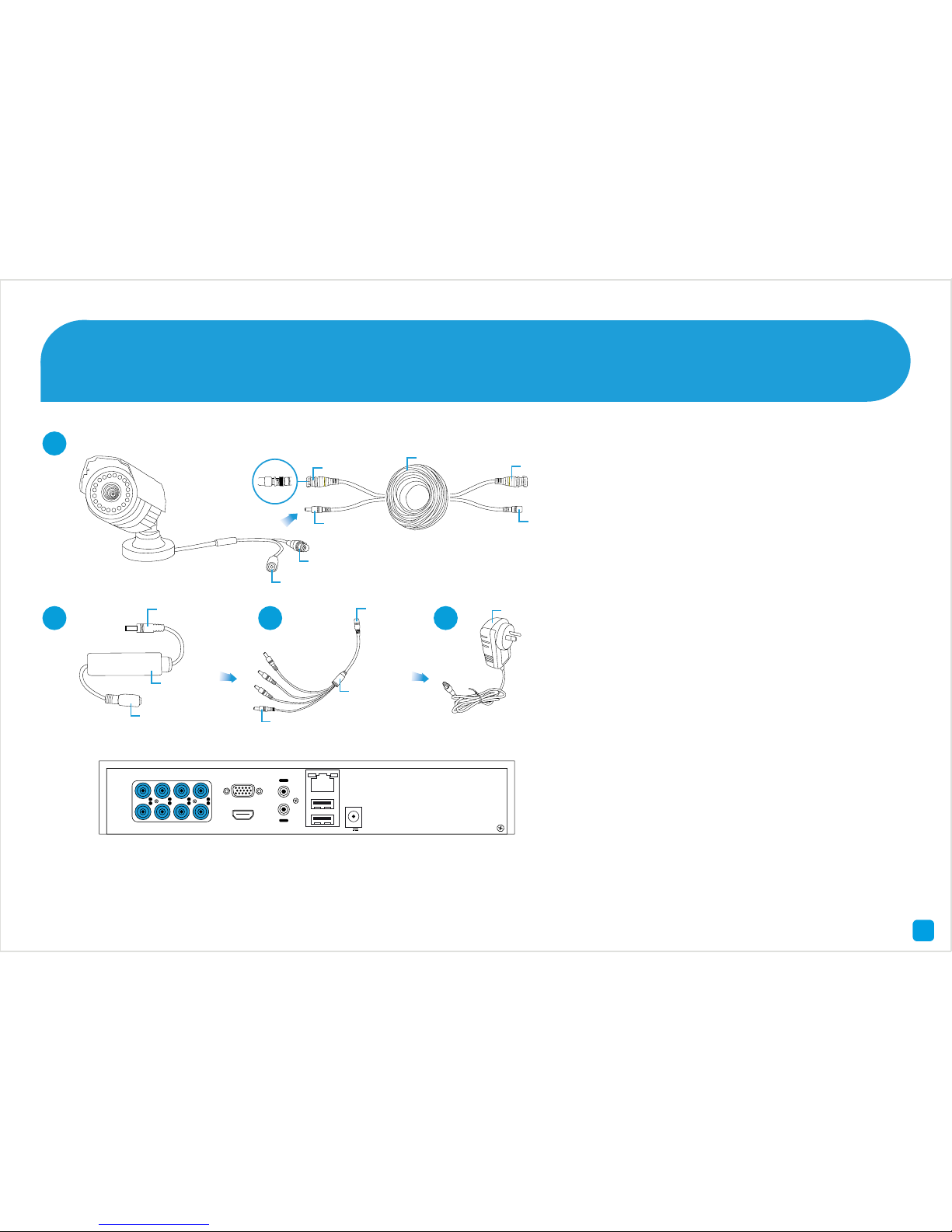
1. Connect the Video Output and Power
Input connections on the camera to
the corresponding connections on the
supplied Video & Power cable.
2. Connect the supplied Inline Filter to
the corresponding power connection
on the Video & Power cable.
3. Connect the supplied Power Splitter
cable to the other end of the Inline
Filter. Repeat the above steps for each
camera included with your DVR.
4. Connect the supplied Power Adapter
to the other end of the Power Splitter
then connect the Power Adapter to
a spare wall socket. Press the wall
socket’s switch to the on position to
supply power to the cameras.
1
2 3 4
Twist to lock
video connectors
1234567
8
ININININ
OUT
VIDEO IN HDMI
VGA
AUDIO LAN & USB
12V
Video Input
Video & Power Cable
Connect this to the DVR
Inline Filter
connects here
Power Adapter
Power Adapter
connects here
Power Splitter
Power Input
Video Output
Power Output
This connects to the
Video & Power Cable
Inline Filter
This connects to the
Power Splitter
Inline Filter
connects here
Page 5
5
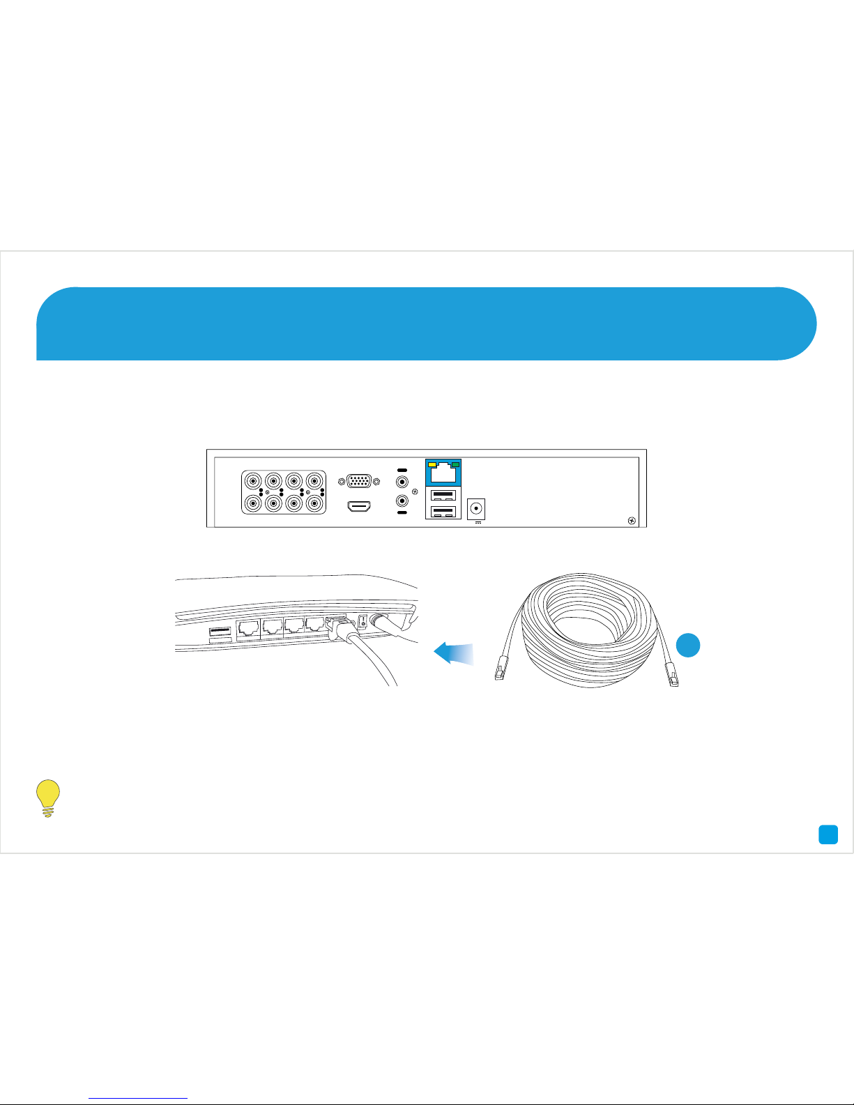
Connect the supplied Ethernet cable (1) to the LAN connection on the DVR then connect the other end to a spare port
on your router or wireless access point.
It’s important that you do this as this allows you to access the DVR from your smartphone or tablet and to send
you email notifications. It also allows the DVR to connect to the Internet to update its internal clock.
Connect the DVR to your Home Network 2
5
1
1234567
8
ININININ
OUT
VIDEO IN HDMI
VGA
AUDIO LAN & USB
12V
USB
Internet
4
3
2
Page 6
8
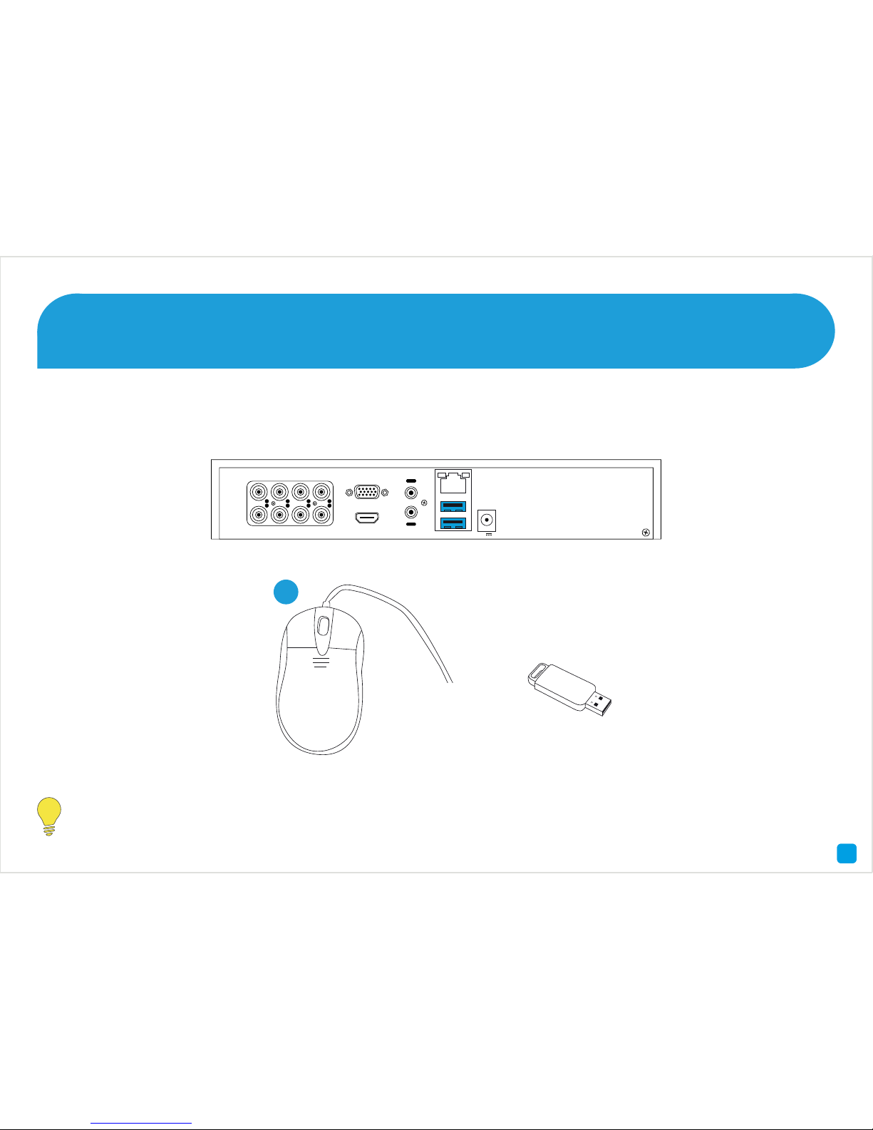
Connect the supplied mouse (1) to one of the available USB ports. You can connect a USB storage device such as a
flash drive to the other port, to back up your video recordings and to perform a firmware upgrade.
Connect the Mouse 3
6
Please note, Bluetooth and wireless mice and trackpad devices are not supported. Not all USB storage devices
are supported.
1
1234567
8
ININININ
OUT
VIDEO IN HDMI
VGA
AUDIO LAN & USB
12V
Page 7
3
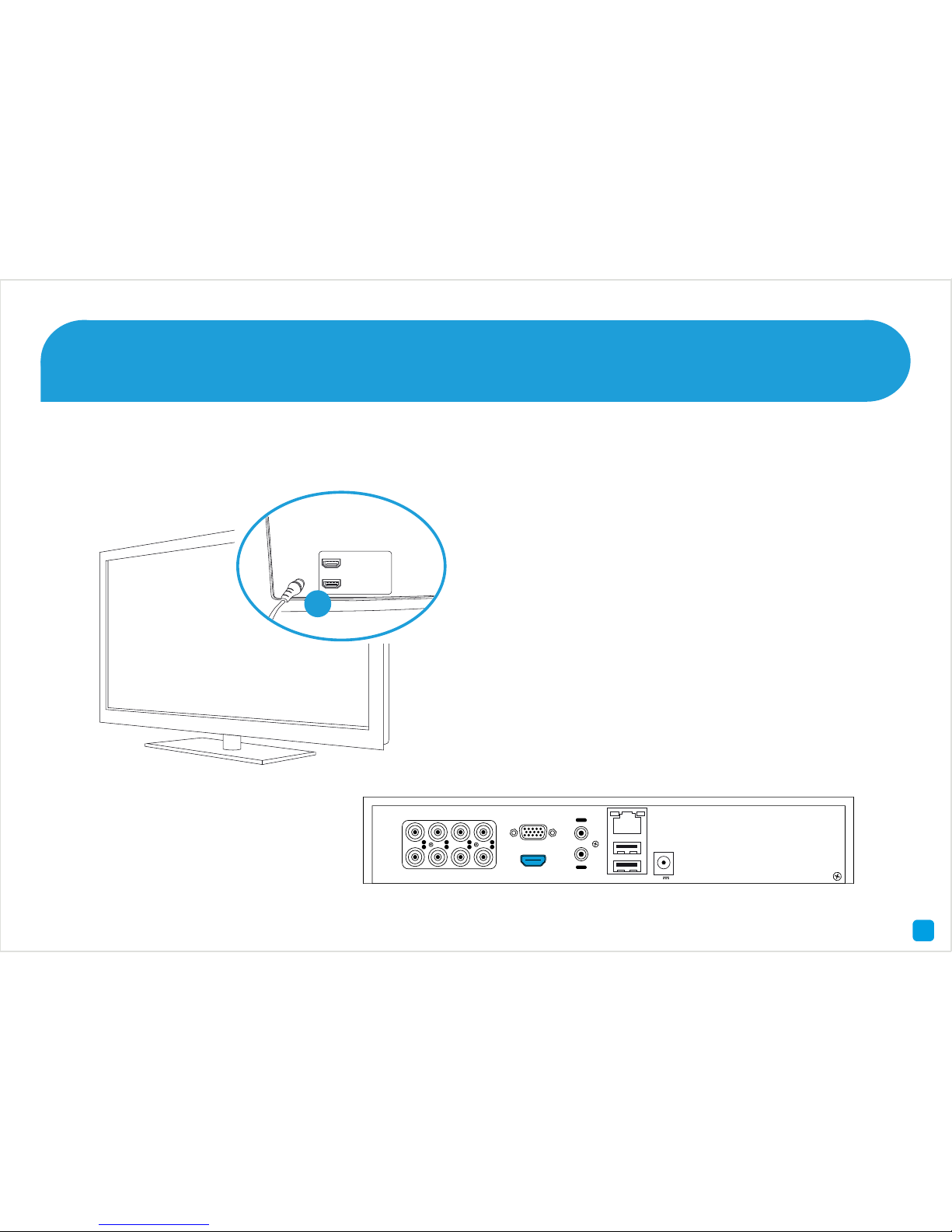
Connect the supplied HDMI cable to the HDMI output on the DVR then connect the other end to a spare HDMI input (1)
on your HDTV. Make sure the video input on the HDTV matches the physical connection used to connect the DVR.
Connect the DVR to your HDTV 4
7
HDMI IN 2
HDMI IN 1
1
1234567
8
ININININ
OUT
VIDEO IN HDMI
VGA
AUDIO LAN & USB
12V
Page 8
6
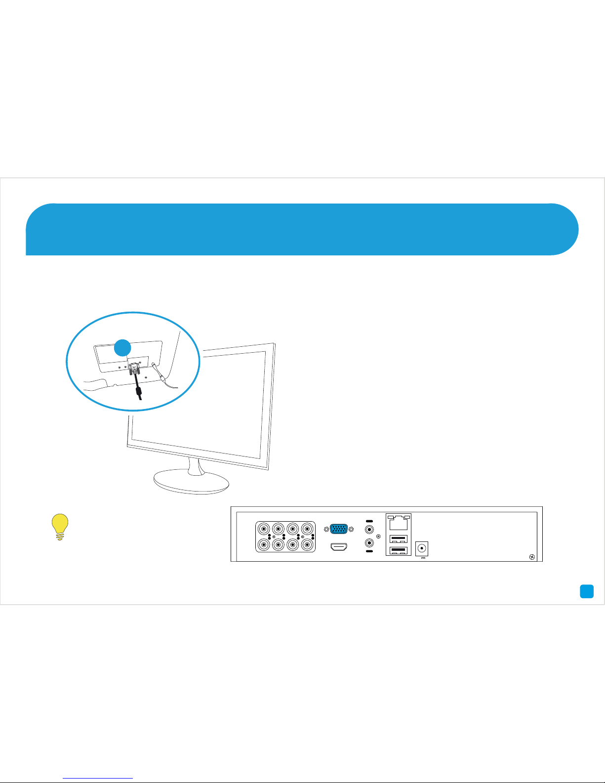
If you have a Monitor with a VGA connection, connect a VGA cable (not supplied) to the VGA output on the DVR then
connect the other end to the VGA input (1) on your Monitor.
Connect the DVR to your Monitor (optional) 5
8
A VGA cable and monitor
are not required when
using the HDMI cable.
1
1234567
8
ININININ
OUT
VIDEO IN HDMI
VGA
AUDIO LAN & USB
12V
Page 9
9
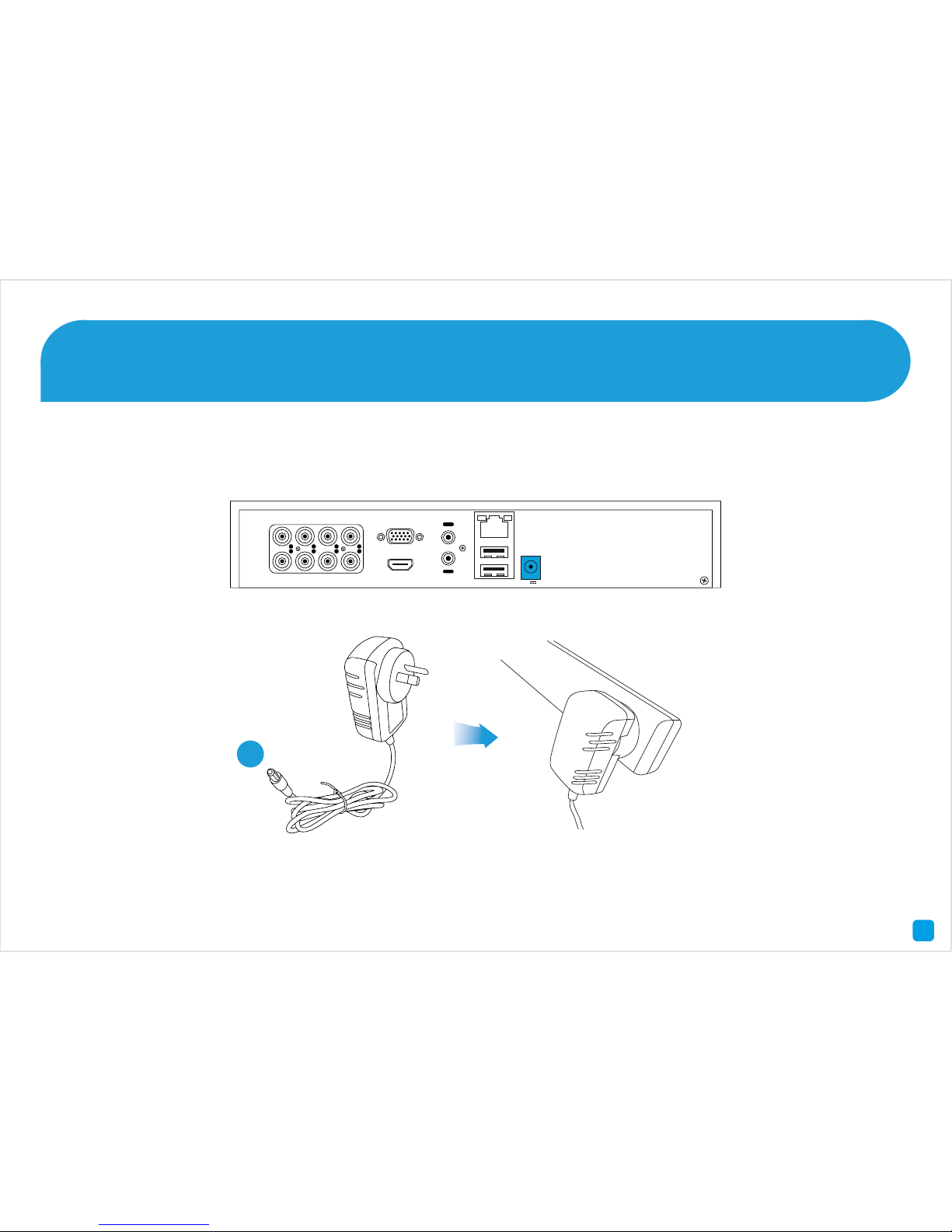
Connect the supplied power adapter’s power connection (1) to the power input on the DVR first (this will minimise
sparking) then connect the power adapter to a spare wall socket.
All the connections have now been completed. You’re now ready to run through “The Setup Wizard” quick start guide
to configure the DVR.
Connect the Power Adapter 6
9
1234567
8
ININININ
OUT
VIDEO IN HDMI
VGA
AUDIO LAN & USB
12V
1
 Loading...