

Page 1
Help Desk / Support Details
12
See http://www.worldtimeserver.com for information on different time
zones and the time in Melbourne Australia compared to your local time.
Warranty Information
Swann Technical Support
All Countries E-mail:
tech@swann.com.au
Telephone Helpdesk
UNITED STATES toll free
877-274-3695
(Sun-Thurs, 2pm-10.30pm PST)
800-627-2799
(Mon-Fri, 9am-1pm PST)
USA Exchange & Repairs
562-777-2551
(Mon-Fri, 9am-5pm PST)
AUSTRALIA toll free
1300 13 8324
(Mon-Fri, 9am-5.30pm Aus EST)
International
+61 3 8412 4610
(Mon-Fri, 9am-5.30pm Aus EST)
English
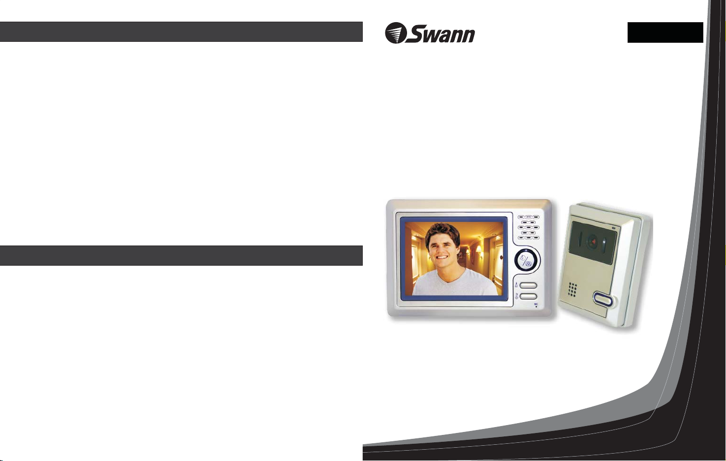
Color Video Doorphone
High Resolution Intercom
Safely see who’s at the door before you answer it
Swann Communications warrants this product against defects in workmanship and material for a
period of one ( ) year from it’s original purchase date. You must present your receipt as proof of
date of purchase for warranty validation. Any unit which proves defective during the stated period
will be repaired without charge for parts or labour or replaced at the sole discretion of Swann. The
repair or replacement will be warranted for either ninety days or the remainder of the original one
year warranty period, whichever is longer. The end user is responsible for all freight charges
incurred to send the product to Swann’s repair centres. The end user is responsible for all shipping
costs incurred when shipping from and to any country other than the country of origin. The
warranty does not cover any incidental, accidental or consequential damages arising from the use of
or the inability to use this product. Any costs associated with the fitting or removal of this product
by a tradesman or other person or any other costs associated with its use are the responsibility of
the end user. This warranty applies to the original purchaser of the product only and is not
transferrable to any third party.
Unauthorised end user or third party modifications to any component or evidence of misuse or
abuse of the device will render all warranties void.
1
Installation Guide
www.swannsecurity.com
Page 2
2
DVR4NET - PLUS
4 Camera Digital Video Recorder
Night Hawk
Wireless Outdoor Camera
Quick User Guide
Firstly check if the monitor is getting power, make sure the 16VDC 1A power supply is
firmly connected to the power socket. Then make sure you have correctly wired the
Doorphone system by referring to the Wiring Diagram illustrations on page 8.
Test by pressing the “Talk/Monitor” button on the monitor. You should see an image from
the intercom unit if the system has been correctly installed.
Frequently Asked Questions
Q.Whycan’tIseethepersonatthedoor?
A. Firstly make sure you have followed the steps in the Quick User Guide above. Then try
adjusting the camera location, viewing direction of the camera, and contrast to improve
the picture.
During times of low light, if you find your visitors are standing too far from the intercom
to be seen, we recommend providing an additional light source to help illuminate the
entrance area.
Q.Whycan’tIhearthepersonatthedoor?
A. Firstly make sure you have followed the steps in the Quick User Guide above. Now try
pressing the “Call” button on the front of the intercom unit. Once the monitor unit
chimes, press the “Talk/Monitor” button to test communications. If you can not hear the
other person, try moving closer to the microphone on the intercom and monitor units.
Q. Why hear the doorbell ring?
A. Firstly make sure you have followed the steps in the Quick User Guide above. To
can’t I
activate the door chime, press the “Call” button on the front of the intercom unit.
11
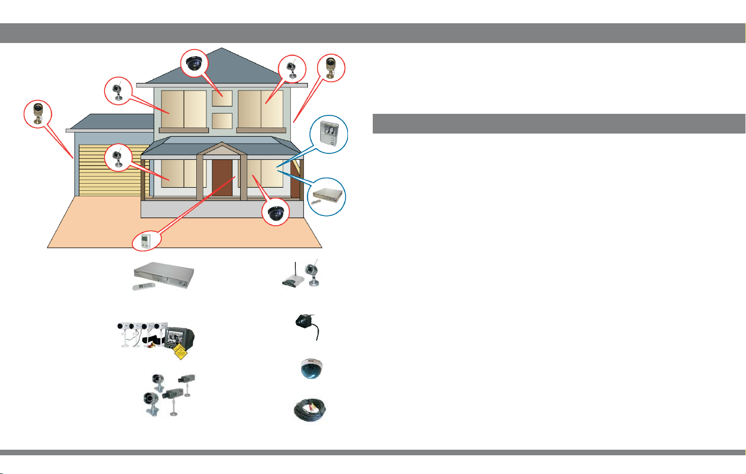
DIY Security Kit
2Real&2ImitationCameras
Security Monitoring System
CCTV Professional 4 Camera Pack
Professional Security Camera
Microcam II
Wireless Security Camera
Imitation Dome Cam
Imitation Security Camera
AVPowerCable-18m/60ft
Camera Accessory
Q. How do I extend the length of the cable from the monitor to intercom unit?
A. You can extend the length of the cable by using (2 x 0.75mm ) copper cable in PVC
2
insulation. For example figure 8 speaker cable.
Q. What type of cable should I use to connect the intercom unit
my electronic door latch?
A. We recommend using (2 x 0.15mm ) copper cable. For example telephone cable.
2
Q. Can I use more than one monitor with my Doorphone system?
However you can use the TV Output to view the images on your TV. Please refer to
A. No.
page 3 for more information.
Page 3

Specifications
Table of Contents
310
Indoor-monitor
Power supply
Power consumption
Operation temperature
Conversation System
Calling Tone
Conversation Time
Scanning Frequency
External dimension
Camera
Power supply
Power consumption
Operation temperature
Picture Sensor
FieldofView
Min. Lighting
Lighting
External dimension
DC16V
About10Winoperation;about0.5Winstandby
5 ~ 122 °F /-15~50°C
Bi-directional conversation through the receiver
¡¡Ding Dong chime
“Ding Dong” chime
Automatic cut off after about 2 minutes
Horizontal:15.625KHz Vertical: 50Hz
7 x5 x1in/185x130x27mm(LxWxH)1/3 1/12
DC12V , 0.25A (supplied by the monitor)
About 2.0W in operation
5 ~ 122 °F /-15~50°C
1/4” CMOS
Diagonal: about 53°
0.1 lux @ about 11.8in/30cm
6 Infrared illuminators
4 x3 x1 in/120x88x34mm(LxWxH)7/12 1/3 1/4
Table of Contents ............................................ 3
Functions .......... .............................................4
Package Contents ...........................................5
Monitor Features ............................................ 6
Camera Features ............................................ 6
Installation .....................................................7
Wiring diagram ............................................... 8
Operation ........................................................9
Specifications .................................................10
Quick User Guide ............................................11
Frequently Asked Questions ............................11
Help Desk / Support Details .............................12
Warranty Information ......................................12
Page 4

4
Functions
Operation
9
Hands free Communication
This device provideshands free communication between the color TFT-LCD monitor and the outdoor
intercom unit. Witha press of a button, you can communicate withthe visitor at the door.
Automatic Display
When the visitorspress the doorbell button , the bell will ringand a picture of the
visitor will beautomatically displayed . You can safely identify thevisitor before talking
or opening thedoor.
Unlock Button
With a buttonfor opening an electronic door latch, you are ableto open the door from the
LCD monitor withoutgoing directly to the door.
* Note: This is an optional extra availablefrom Swann. (SW-D-LOCK)
Night Vision
The 6 infraredLEDs on the camera allows you to recognize thevisitor during times of low light.
* Night visiondistance will vary with the amount of available light.
Visitor at the door
mic mic
Press " ”button
The
A visitor pressesthe
"call" button on the
intercom.
Once ress "talk” button to LCD
you p communicate with the visitor, the monitor will be shut down
automatically .
When the visitor presses the “call” button,t f no one
answers, the monitor will automatically go backinto standby mode after 60 seconds.
in 2 minutes
door phone will ring and
visitor
the is displayed on
the
LCD monitor.
he picture will bedisplayed on the LCD monitor. I
the talk to
communicate with the visitor.
Other operations
Warning button
If youget malice visitors,you can presswarning button. The intercom unit will give an audible alarm
and bringattention to areaaround the intercomunit.
Adjustable volume/contrast
If youthink the monitorvolume is notloud enough orthe picture shownon the screenis too bright,
you canalter this byadjusting the volumeor contrast wheelfound underneath theLCD monitor
.
Page 5

8
Wiring Diagram
Package Contents
mic
5
C
D
A B
Monitor
Intercom
Unit
Non-Polarity cable
Lock
Please disconnect the power supply fromthe monitor before connectingthe monitor to the
intercom unit.
Open the door with the touch of a button by installing
Swann’s Electric Door Strike* (SW-D-LOCK).
*Sold separately
Monitor
Support for Wall-mount
Installation guide
Important Informations
Do not put the doorphone near strong
magnetic fields, such as a television
or video recorder .
Do not spray water directly on thevideo
doorphone.
Do not place unit in direct sunlightor expose it
to rain.
Intercom unit
ANDFREE
ANDFREE
H
H
OORPHONE
OORPHONE
IRE
IRE
D
D
W
W
IDEO
IDEO
TWO
TWO
V
nd
V
a
COLOR
COLOR
anual
M
Installation
Operation
IRE
W
2
NONPOLARITY
FT-LCD
T
COLOR
HANDFREE
Camera bracket
Screws
Turn off the powerif not use for long time.
Do not damage the video doorphone.
There may be high voltage inside thesystem,
do not under any circumstances disassemble
this device.
Page 6

6
Monitor Features
Loud Speaker
Installation of the monitor
AC:110~240V
7
Screen
mic
DC 16V
Volume
wheel
Audio/Video wire
A/V OUT
Contrast
wheel
Toview the image on your TV, connect the Audio/Video wirefrom the AV OUTon the
LCD monitor to an AV INPUTon your TV.
Camera Features
Switch for adjusting camera angle
(move up to tilt cameradown and
Mic ophoner
Infrared LEDs
Loud Speaker
Camera Lens
Light
Call button
move down to tilt cameraup)
Talk / Monitor
Button
Warning Button
Doorlatch Unlock Button
Mic ophoner
VCR, TV or MONITOR
audio
(white andred)
video(yellow)
AV INPUT
C
D
A B
4.7-5.2ft / 145 - 160cm
A good heightto place
4.7-5.2 ft / g
is 145~160cm from round.
the monitor
mic
Fix the wall mount using the supplied
screws and attach
on the wall
then the monitor.
Installation of the camera
Positioning the lens using the switch on the back
of the camera to adjust the angle of the lens:
Standard h
VIDEO
AUDIO
OUT
IN
VIDEO
AUDIO
eight
of the camera
66¡
4.7-5.2ft /145 - 160cm
50cm
Move it down
23¡
4.7-5.2ft /145 - 160cm
50cm
Move it up
43¡
4.7-5.2ft /145 - 160cm
50cm
Horizontal angle
the cameraof
53¡
Location:
Keep the camera away from direct sunlight
and the effects of poor weather.
 Loading...