

Swann AMU pH-Redox Operator's Manual
AMU pH-Redox
Version 6.20 and higher
s Manual
Operator’
A-96.250.441 / 060619

Customer Support
SWAN and its representatives maintain a fully trained staff of technical specialists
around the world. For any technical question, contact your nearest
SWAN representative, or the manufacturer:
SWAN ANALYTISCHE INSTRUMENTE AG
Studbachstrasse 13
8340 Hinwil
Switzerland
Internet: www.swan.ch
E-mail: support@swan.ch
Document Status
Title:
ID:
AMU pH-Redox Operator’s Manual
A-96.250.441
Revision Issue
00 Sept. 2006 First Edition
01 June 2019 Update to firmware V6.20
© 2019, SWAN ANALYTISCHE INSTRUMENTE AG, Switzerland, all rights reserved
subject to change without notice.

AMU pH-Redox
Table of Contents
1. Safety Instructions . . . . . . . . . . . . . . . . . . . . . . . . . . . . . . . . . . . 4
1.1. Warning Notices . . . . . . . . . . . . . . . . . . . . . . . . . . . . . . . . . . . . . . 5
1.2. General Safety Regulations . . . . . . . . . . . . . . . . . . . . . . . . . . . . . 6
2. Product Description . . . . . . . . . . . . . . . . . . . . . . . . . . . . . . . . . . 8
2.1. Description of the System. . . . . . . . . . . . . . . . . . . . . . . . . . . . . . . 8
2.2. Single Components . . . . . . . . . . . . . . . . . . . . . . . . . . . . . . . . . . . 13
2.2.1 AMU pH-Redox Transmitter . . . . . . . . . . . . . . . . . . . . . . . . . . . 13
2.2.2 Flow Cell M-Flow 10-3PG . . . . . . . . . . . . . . . . . . . . . . . . . . . . . 14
2.2.3 Flow Cell QV-Flow SS316L pHRT . . . . . . . . . . . . . . . . . . . . . . 15
2.2.4 Flow Cell B-Flow IS1000. . . . . . . . . . . . . . . . . . . . . . . . . . . . . . 16
2.2.5 Swansensor pH and Redox Standard. . . . . . . . . . . . . . . . . . . . 17
2.2.6 Swansensor pH and Redox AY. . . . . . . . . . . . . . . . . . . . . . . . . 18
2.2.7 Swansensor pH and Redox SI . . . . . . . . . . . . . . . . . . . . . . . . . 19
2.2.8 Swansensor pH and Redox FL . . . . . . . . . . . . . . . . . . . . . . . . . 20
2.2.9 Swansensor Reference FL . . . . . . . . . . . . . . . . . . . . . . . . . . . . 21
2.2.10 Spray Nozzle. . . . . . . . . . . . . . . . . . . . . . . . . . . . . . . . . . . . . . . 21
3. Installation. . . . . . . . . . . . . . . . . . . . . . . . . . . . . . . . . . . . . . . . . . 22
3.1. Installation Checklist Monitors . . . . . . . . . . . . . . . . . . . . . . . . . . . 22
3.2. Dimensions of the AMU Transmitter. . . . . . . . . . . . . . . . . . . . . . . 23
3.3. Connecting Sample Inlet and Outlet. . . . . . . . . . . . . . . . . . . . . . . 24
3.3.1 Serto Fitting Stainless Steel for QV-Flow Cell. . . . . . . . . . . . . . 24
3.3.2 Elbow Hose Nozzle for M-Flow Cell . . . . . . . . . . . . . . . . . . . . . 24
3.4. Flow Cell QV-Flow . . . . . . . . . . . . . . . . . . . . . . . . . . . . . . . . . . . . 25
3.4.1 Install Swansensor pH or Redox SI . . . . . . . . . . . . . . . . . . . . . 25
3.4.2 Adapter Set . . . . . . . . . . . . . . . . . . . . . . . . . . . . . . . . . . . . . . . . 27
3.5. Flow Cell M-Flow . . . . . . . . . . . . . . . . . . . . . . . . . . . . . . . . . . . . . 28
3.5.1 Install Swansensor pH/Redox Standard or AY . . . . . . . . . . . . . 28
3.6. Connect the Swansensor . . . . . . . . . . . . . . . . . . . . . . . . . . . . . . . 30
3.7. Install Spray Nozzle (Option) into M-Flow Cell . . . . . . . . . . . . . . . 31
3.8. Electrical Connections . . . . . . . . . . . . . . . . . . . . . . . . . . . . . . . . . 32
3.9. Power supply . . . . . . . . . . . . . . . . . . . . . . . . . . . . . . . . . . . . . . . . 34
3.10. Sensor . . . . . . . . . . . . . . . . . . . . . . . . . . . . . . . . . . . . . . . . . . . . . 34
3.11. Flow Meter . . . . . . . . . . . . . . . . . . . . . . . . . . . . . . . . . . . . . . . . . . 34
3.12. Input . . . . . . . . . . . . . . . . . . . . . . . . . . . . . . . . . . . . . . . . . . . . . . . 34
3.13. Relay Contacts . . . . . . . . . . . . . . . . . . . . . . . . . . . . . . . . . . . . . . . 35
3.13.1 Alarm Relay. . . . . . . . . . . . . . . . . . . . . . . . . . . . . . . . . . . . . . . . 35
A-96.250.441 / 060619 1

AMU pH-Redox
3.13.2 Relay 1 and 2 . . . . . . . . . . . . . . . . . . . . . . . . . . . . . . . . . . . . . . 35
3.14. Signal Output 1 and 2 (current outputs) . . . . . . . . . . . . . . . . . . . . 35
3.15. Interfaces . . . . . . . . . . . . . . . . . . . . . . . . . . . . . . . . . . . . . . . . . . . 36
3.15.1 RS232 Interface. . . . . . . . . . . . . . . . . . . . . . . . . . . . . . . . . . . . . 36
3.15.2 Profibus (optional) . . . . . . . . . . . . . . . . . . . . . . . . . . . . . . . . . . . 36
3.15.3 Modbus (optional) . . . . . . . . . . . . . . . . . . . . . . . . . . . . . . . . . . . 37
4. Instrument Setup . . . . . . . . . . . . . . . . . . . . . . . . . . . . . . . . . . . . 38
4.1. Establish Sample Flow . . . . . . . . . . . . . . . . . . . . . . . . . . . . . . . . . 38
4.2. Programming . . . . . . . . . . . . . . . . . . . . . . . . . . . . . . . . . . . . . . . . 38
5. Operation. . . . . . . . . . . . . . . . . . . . . . . . . . . . . . . . . . . . . . . . . . . 40
5.1. Keys . . . . . . . . . . . . . . . . . . . . . . . . . . . . . . . . . . . . . . . . . . . . . . . 40
5.2. Display . . . . . . . . . . . . . . . . . . . . . . . . . . . . . . . . . . . . . . . . . . . . . 41
5.3. Software Structure . . . . . . . . . . . . . . . . . . . . . . . . . . . . . . . . . . . . 42
5.4. Changing Parameters and values. . . . . . . . . . . . . . . . . . . . . . . . . 43
6. Maintenance . . . . . . . . . . . . . . . . . . . . . . . . . . . . . . . . . . . . . . . . 44
6.1. Maintenance Table . . . . . . . . . . . . . . . . . . . . . . . . . . . . . . . . . . . . 44
6.2. Stop of Operation for Maintenance. . . . . . . . . . . . . . . . . . . . . . . . 45
6.3. Maintenance of Electrodes . . . . . . . . . . . . . . . . . . . . . . . . . . . . . . 45
6.3.1 Clean pH/ ORP SI or FL Electrodes . . . . . . . . . . . . . . . . . . . . . 45
6.3.2 Clean pH/ORP Standard or AY Electrodes. . . . . . . . . . . . . . . . 47
6.4. Calibration. . . . . . . . . . . . . . . . . . . . . . . . . . . . . . . . . . . . . . . . . . . 48
6.5. Longer Stop of Operation . . . . . . . . . . . . . . . . . . . . . . . . . . . . . . . 52
7. Error List . . . . . . . . . . . . . . . . . . . . . . . . . . . . . . . . . . . . . . . . . . . 53
8. Program Overview . . . . . . . . . . . . . . . . . . . . . . . . . . . . . . . . . . . 56
8.1. Messages (Main Menu 1) . . . . . . . . . . . . . . . . . . . . . . . . . . . . . . . 56
8.2. Diagnostics (Main Menu 2) . . . . . . . . . . . . . . . . . . . . . . . . . . . . . . 57
8.3. Maintenance (Main Menu 3) . . . . . . . . . . . . . . . . . . . . . . . . . . . . . 58
8.4. Operation (Main Menu 4) . . . . . . . . . . . . . . . . . . . . . . . . . . . . . . . 58
8.5. Installation (Main Menu 5). . . . . . . . . . . . . . . . . . . . . . . . . . . . . . . 59
9. Program List and Explanations. . . . . . . . . . . . . . . . . . . . . . . . . 61
1 Messages. . . . . . . . . . . . . . . . . . . . . . . . . . . . . . . . . . . . . . . . . . 61
2 Diagnostics . . . . . . . . . . . . . . . . . . . . . . . . . . . . . . . . . . . . . . . . 61
3 Maintenance . . . . . . . . . . . . . . . . . . . . . . . . . . . . . . . . . . . . . . . 63
4 Operation . . . . . . . . . . . . . . . . . . . . . . . . . . . . . . . . . . . . . . . . . . 64
5 Installation . . . . . . . . . . . . . . . . . . . . . . . . . . . . . . . . . . . . . . . . . 65
2 A-96.250.441 / 060619

AMU pH-Redox
10. Safety Data sheets . . . . . . . . . . . . . . . . . . . . . . . . . . . . . . . . . . . 80
11. Default Values. . . . . . . . . . . . . . . . . . . . . . . . . . . . . . . . . . . . . . . 81
12. Index . . . . . . . . . . . . . . . . . . . . . . . . . . . . . . . . . . . . . . . . . . . . . . 84
13. Notes . . . . . . . . . . . . . . . . . . . . . . . . . . . . . . . . . . . . . . . . . . . . . . 86
A-96.250.441 / 060619 3

AMU pH-Redox
Safety Instructions
AMU pH-Redox - Operator’s Manual
This document describes the main steps for instrument setup, operation and maintenance.
1. Safety Instructions
General The instructions included in this section explain the potential risks
Targ et
audience
OM Location The AMI Operator’s Manual shall be kept in proximity of the instru-
Qualification,
Training
associated with instrument operation and provide important safety
practices designed to minimize these risks.
If you carefully follow the information contained in this section, you
can protect yourself from hazards and create a safer work environment.
More safety instructions are given throughout this manual, at the
respective locations where observation is most important.
Strictly follow all safety instructions in this publication.
Operator: Qualified person who uses the equipment
for its intended purpose.
Instrument operation requires thorough knowledge of applications,
instrument functions and software program as well as all applicable
safety rules and regulations.
ment.
To be qualified for instrument installation and operation, you must:
read and understand the instructions in this manual as well as
the Material Safety Data Sheets.
know the relevant safety rules and regulations.
4 A-96.250.441 / 060619
AMU pH-Redox
Safety Instructions
1.1. Warning Notices
The symbols used for safety-related notices have the following significance:
DANGER
Your life or physical wellbeing are in serious danger if such
warnings are ignored.
Follow the prevention instructions carefully.
WARNING
Severe injuries or damage to the equipment can occur if such
warnings are ignored.
Follow the prevention instructions carefully.
CAUTION
Damage to the equipment, minor injury, malfunctions or incorrect process can be the consequence if such warnings are ignored.
Follow the prevention instructions carefully.
Mandatory
Signs
A-96.250.441 / 060619 5
The importance of the mandatory signs in this manual.
Safety goggles
Safety gloves
AMU pH-Redox
Safety Instructions
Warning Signs The importance of the warning signs in this manual.
Electrical shock hazard
Corrosive
Harmful to health
Flammable
Warning general
Attention general
1.2. General Safety Regulations
Legal
Requirements
Spare Parts
and
Disposables
Modifications Modifications and instrument upgrades shall only be carried out by
The user is responsible for proper system operation. All precautions must be followed to ensure safe operation of the instrument.
Use only official SWAN spare parts and disposables. If other parts
are used during the normal warranty period, the manufacturer’s
warranty is voided.
an authorized Service Technician. SWAN will not accept responsibility for any claim resulting from unauthorized modification or alteration.
6 A-96.250.441 / 060619
AMU pH-Redox
Safety Instructions
WARNING
Risk of Electrical Shock
If proper operation is no longer possible, the instrument must be
disconnected from all power lines, and measures must be taken
to prevent inadvertent operation.
To prevent from electrical shock, always make sure that the
Service shall be performed by authorized personnel only.
Whenever electronic service is required, disconnect instru-
WARNING
For safe instrument installation and operation you must read
and understand the instructions in this manual.
ground wire is connected.
ment power and power of devices connected to.
– relay 1,
– relay 2,
– alarm relay
WARNING
Only SWAN trained and authorized personnel shall perform the
tasks described in this document.
Download
MSDS
A-96.250.441 / 060619 7
The current Safety Data Sheets (SDS) for the above listed Reagents are available for downloading at www.swan.ch.

AMU pH-Redox
Product Description
2. Product Description
2.1. Description of the System
Application pH and ORP are measured in many applications as for example
pH Measuring
Principle
(simplified)
ORP Measur-
ing Principle
(simplified)
Tem per atu re
compensation
potable water, high purity water or waste water. Each application
requires different fittings, flow cells, and sensors.
The pH measurement is based on a voltage measurement. A voltage can only be measured between two different potentials, therefore, the pH measuring chain contains a measuring electrode and a
reference electrode. The reference electrode maintains a constant
potential whereas the potential of the measuring electrode changes
with the pH value. The voltage which results from this potential difference is measured and displayed on the transmitter as pH value.
The measuring chain is designed so that the voltage is zero at
pH 7.
The ORP (redox) measurement is based on a voltage measurement. A voltage can only be measured between two different potentials, therefore, the ORP (redox) measuring chain contains a
measuring electrode and a reference electrode. The reference
electrode maintains a constant potential whereas the potential of
the measuring electrode changes with the ORP value. The voltage
which results from this potential difference is measured and displayed on the transmitter as ORP value in millivolt (mV). Both electrodes are integrated in one housing = combined electrode.
pH: The pH value depends on the sample temperature. To
compensate temperature fluctuations a temperature sensor is
installed in the flow cell.
ORP: Temperature compensation is not necessary.
Potable water, waste water: Compensation according to Nernst.
High purity water (Power plant, semiconductor): Nernst or non-lin-
ear solution temperature compensation, or linear compensation
with coefficient.
8 A-96.250.441 / 060619

AMU pH-Redox
Product Description
Signal
Outputs
Relays Two potential-free contacts programmable as limit switches for
Alarm Relay One potential free contact.
Input One input for potential-free contact to freeze the measuring value
Communica-
tion Interface
Safety
Features
pH Electrode For the AMU pH-Redox four types of pH electrodes are available.
Two signal outputs programmable for measured values (freely scalable, linear, bilinear, log) or as continuous control output (control
parameters programmable).
Current loop: 0/4–20 mA
Maximal burden: 510 Ω
measuring values, controllers or timer for system cleaning with automatic hold function.
Maximum load: 100 mA/ 50 V
Open (closed)* during normal operation, closed (open)* on error
and power loss (* as defined when ordering). Summary alarm indication for programmable alarm values and instrument faults.
Maximum load: 100 mA/ 50 V
or to interrupt control in automated installations (hold function or remote off).
RS232 interface for logger download with HyperTerminal
RS485 interface with Fieldbus protocol Modbus or Profibus DP
(optional)
No data loss after power failure. All data is saved in non-volatile
memory. Over voltage protection of in- and outputs. Galvanic separation of measuring inputs and signal outputs.
The Swansensor pH Standard is a combined gel electrode for
application in drinking water and swimming pools. Gel electrodes
can not be filled again and have a limited life time.
The Swansensor pH SI is a combined electrode with liquid
electrolyte (KCl) for the measurement of pH in power plants.
The Swansensor pH AY is a combined gel electrode for
application in waste water due to additional salt supplies
The Swansensor pH FL for the measurement of pH in high purity
water. This sensor can only be used in combination with
Swansensor Reference FL, A-87.860.100.
A-96.250.441 / 060619 9

AMU pH-Redox
Product Description
ORP Electrode For the AMU pH-Redox four types of redox (ORP) electrodes are
available.
The Swansensor redox (ORP) Standard is a combined gel
electrode for application in drinking water and swimming pools.
Gel electrodes can not be filled again and have a limited life time.
The Swansensor redox (ORP) SI is a combined electrode with
liquid electrolyte (KCl) for the measurement of redox (ORP) value
in power plants.
The Swansensor redox (ORP) AY is a combined gel electrode for
application in waste water due to additional salt supplies.
The Swansensor ORP FL for the measurement of the redox
potential in high purity water. This sensor can only be used in
combination with Swansensor Reference FL,
A-87.860.100.
Reference
electrode
Consumables One 200 ml bottle of 3.5 M KCl lasts for 1 month.
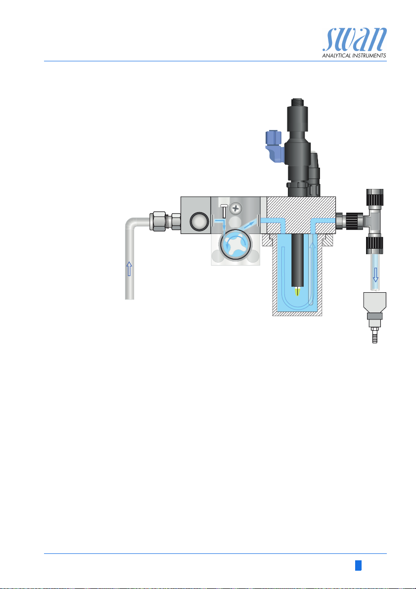
Fluidics
QV-Flow
Swansensor Reference FL, reference electrode for Swansensor pH
FL or Swansensor Redox FL
The flow cell QV-Flow consists of the flow regulating valve [D], the
flow sensor [F], the flow cell block [E], the vessel [G] and a built-in
temperature sensor [B].
The sample enters at the sample inlet [C]. It flows through the flow
regulating valve [D], where the flow rate can be adjusted. Then the
sample flows via the flow sensor [F] and the flow cell block [E] into
the vessel [G], were the pH of the sample is measured. The pH value depends on the sample temperature. The measuring value of
the temperature sensor [B] is used to recalculate the pH measuring
value to the standard sample temperature of 25 °C.
The sample leaves the vessel via flow cell block through the sample outlet [H] and flows into the pressure free drain [I].
10 A-96.250.441 / 060619
AMU pH-Redox
Product Description
CD E
A
B
FG
H
I
A
pH sensor
B
Temperature sensor
C
Sample inlet (stainless steel
tube)
D
Flow regulating valve
A-96.250.441 / 060619 11
E
Flow cell block
F
Flow sensor
G
Vessel (stainless steel)
H
Sample outlet
I
Drain
AMU pH-Redox
Product Description
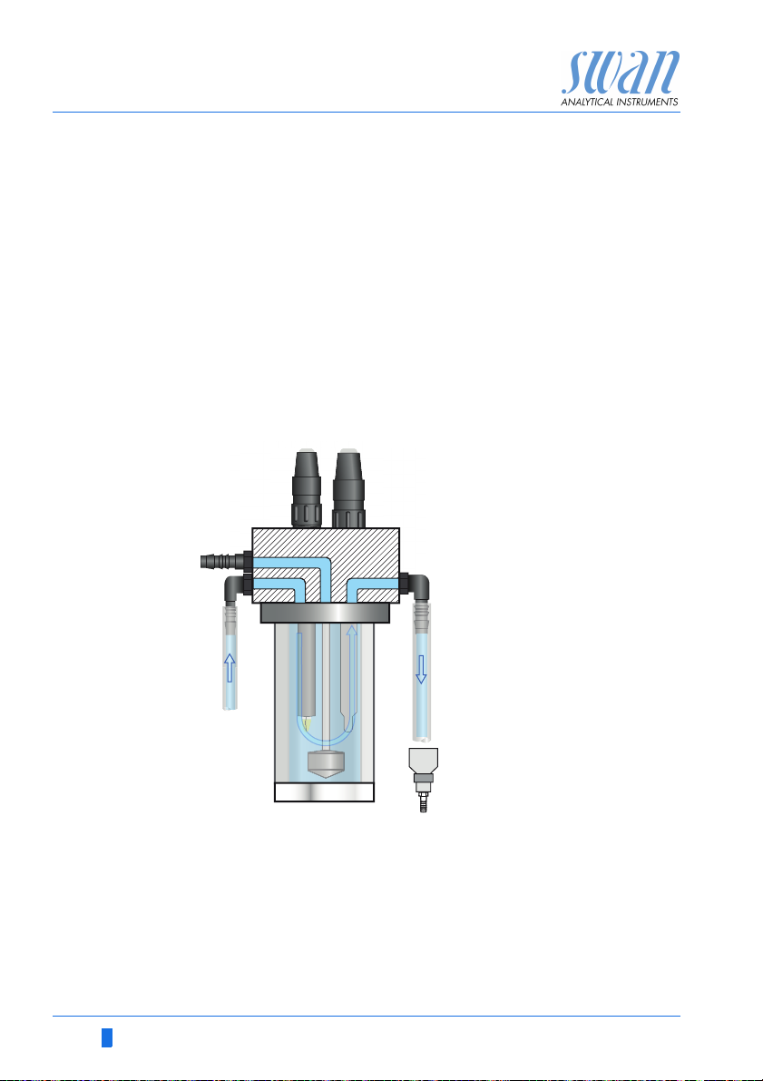
Fluidics
M-Flow
The flow cell M-Flow 10-3PG consists of the flow cell block [C] and
the calibration vessel [D]. The pH sensor [A] and the temperature
sensor [B] are screwed into the flow cell block [C].
Optionally a spray nozzle [F] can be installed. The spray nozzle allows the cleaning of the sensor tips without removing the sensors.
The sample enters at the sample inlet [H] and flows then through
the flow cell block into the calibration vessel [D], were pH and redox
are measured. The pH value depends on the sample temperature.
The measuring value of the temperature sensor [B] is used to recalculate the pH measuring value to a predefined average sample
temperature.
The sample leaves the calibration vessel via flow cell block through
the sample outlet [E] and flows into the pressure free drain [G].
AB
C
D
H
E
A
pH sensor
B
Temperature sensor
C
Flow cell block
D
Calibration vessel
F
G
E
F
G
H
Sample outlet
Spray nozzle
Drain
Sample inlet
12 A-96.250.441 / 060619
AMU pH-Redox
Product Description
2.2. Single Components
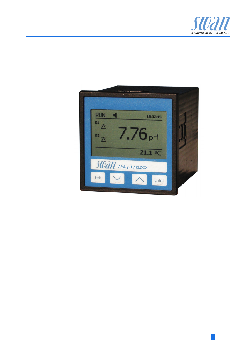
2.2.1 AMU pH-Redox Transmitter
General Electronics housing:
Protection degree:
Ambient temperature:
Humidity:
Display:
Dimensions:
Weight:
Power supply Voltage:
Power consumption:
pH
Measuring range:
measurement
ORP
measurement
A-96.250.441 / 060619 13
Resolution
Reference temperature:
Measuring range:
Resolution:
®
resin
Noryl
IP54 (front)
-10 to +50 °C
10–90% rel., non condensing
backlit LCD, 75 x 45 mm
96 x 96 x 120 mm (DIN 43700)
0.45 kg
100–240 VAC (±10%)
50/60 Hz (±5%)
or 24 VDC (±15%)
max. 8 VA
0.00 to 14.00
0.01
25 °C
-500 to +1500 mV
1 mV
AMU pH-Redox
Product Description
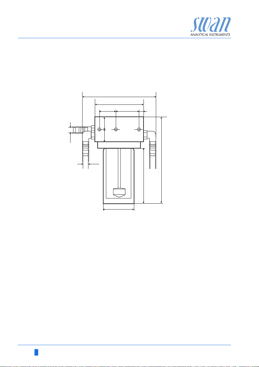
2.2.2 Flow Cell M-Flow 10-3PG
Flow cell for potable water applications for the installation of three
sensors, i.e. a pH or redox sensor, a reference sensor and a temperature sensor. Sensor cleaning available as an option.
142
90
33 38
9
10
23 23
10
60
Connections Sample:
Cleaning water:
Sensor:
Equipped with elbow hose nozzle for 10 mm tube.
Sample For the flow cell without electrodes!
conditions Flow rate:
Temperature:
Inlet pressure:
Outlet pressure:
Particle size:
No strong acids and bases.
No organic solvents.
Dimensions Width:
Front-to-back:
Height:
Mounting:
161
102
G 1/4” thread
G 1/4” thread
Screw connection: PG 13.5 mm
Installation depth:120 mm
4 to 15 l/h
up to 50 °C
up to 1 bar @ 25 °C
Pressure free
below 0.5 mm
90 to 142 mm
138 mm
161 mm
3 screws M5
14 A-96.250.441 / 060619
AMU pH-Redox
169
195
118
101
143
74
127
71
7.5
95
13
9
22.5
29
43
Product Description
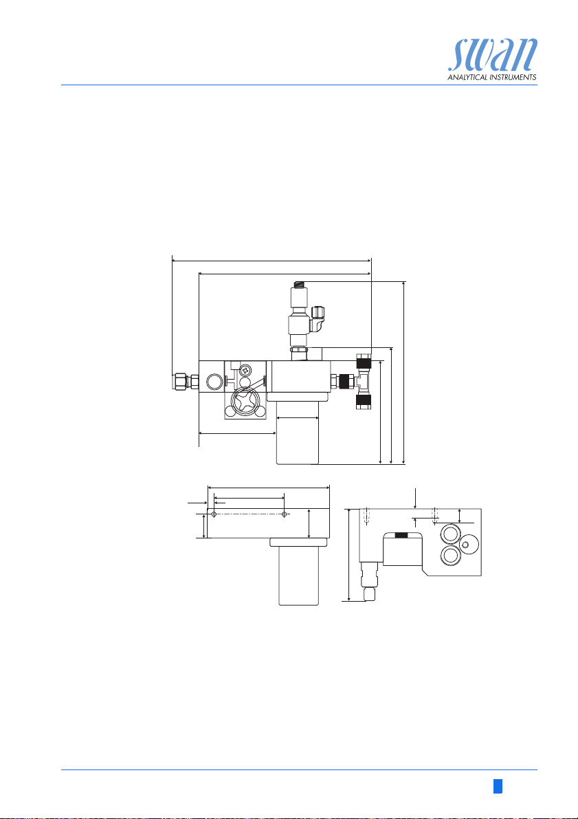
2.2.3 Flow Cell QV-Flow SS316L pHRT
Made of stainless steel SS316L with built-in Pt1000 temperature
sensor and a Swagelok connection for 1/4" tube. With flow measurement and needle valve.
For the installation of two sensors i.e. a pH or redox sensor and a
reference sensor. Recommended for the use with Swansensor pH/
Redox SI. Other sensors require an adapter set for installation.
Technical data Sample inlet:
Sample outlet:
Sample temperature:
Sample flow:
A-96.250.441 / 060619 15
Pressure:
Sensor:
Swagelok G 1/4” thread
Serto 90° angle for 8x6 mm tube
(tube 1.5 m included in delivery)
0–50 °C
5–10 l/h
max. 2 bar at 50 °C
Sample outlet pressure free
Screw connection: PG 13,5 mm
Installation depth: 75 mm
AMU pH-Redox
88
65
20
23
94
29
55
120
198
29
Product Description
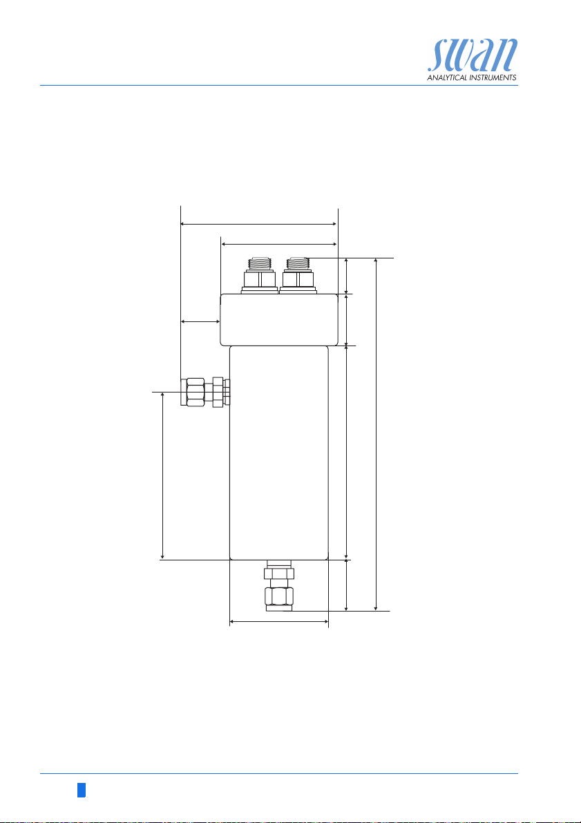
2.2.4 Flow Cell B-Flow IS1000
Stainless steel flow cell for 2 sensors with integrated Pt1000 temperature sensor. Suitable for all sensors with PG13.5 screw head
and a max. shaft length of 120 mm.
Technical data Sample inlet and outlet:
Operating temperature flow cell:
Operating temperature sensors:
Operating pressure low cell:
Operating pressure sensors:
2 x ¼" NPT female thread
up to 130 °C
up to 50 °C
max. 10 bar
max. 5 bar
16 A-96.250.441 / 060619
AMU pH-Redox
31
13
Ø 12
120 ±2
Product Description
2.2.5 Swansensor pH and Redox Standard
Combined electrode with gel electrolyte for application in drinking
water and swimming pools.
pH-Sensor Redox Sensor Sensor cable with
plug
Specifications
pH Sensor
Specifications
ORP Sensor
A-96.250.441 / 060619 17
Operative and measuring range:
Operating temperature:
Pressure:
Conductivity measuring medium:
Connection:
Operative and measuring range:
Operating temperature:
Pressure:
Conductivity measuring medium:
Connection:
1 to 13 pH
0–50 °C
<2 bar
>150 µS/cm
plug PG 13.5
-400 to +1200 mV
0–50 °C
<2 bar
>150 µS/cm
plug PG 13.5
AMU pH-Redox
31
13
Ø 12
120 ±2
Product Description
2.2.6 Swansensor pH and Redox AY
Combined electrode with gel electrolyte for application in waste water due to additional salt supplies.
pH-Sensor Redox Sensor Sensor cable with
plug
Specifications
Specifications
pH-Sensor
ORP-Sensor
Operative and measuring range:
Operating temperature:
Pressure:
Conductivity measuring medium:
Connection:
Operative and measuring range:
Operating temperature:
Pressure:
Conductivity measuring medium:
Connection:
1 to 13 pH
0–50 °C
<2 bar
>100 µS/cm
plug PG 13.5
-400 to +1200 mV
0–50 °C
<2 bar
>100 µS/cm
plug PG 13.5
18 A-96.250.441 / 060619
AMU pH-Redox
Product Description
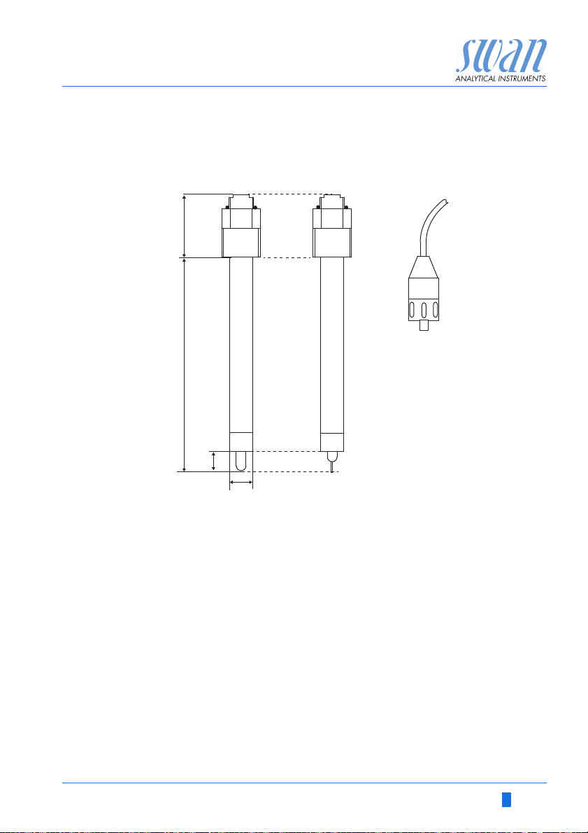
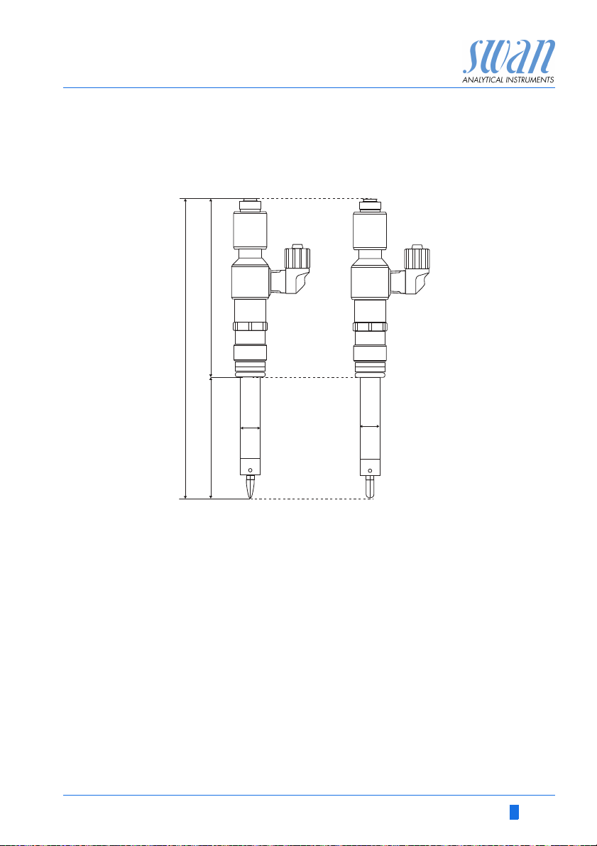
2.2.7 Swansensor pH and Redox SI
pH/Redox electrode with reference electrode for the measurement
of pH/Redox value in power plants.
184
110
75
12
12
pH Sensor Redox Sensor
Specifications
pH-Sensor
Specifications
Redox-Sensor
A-96.250.441 / 060619 19
Operative and measuring range:
Operating temperature:
Electrolyte:
Pressure:
min. Conductivity:
Connection:
Operative and measuring range:
Operating temperature:
Electrolyte:
Pressure:
min. Conductivity:
Connection:
1 to 12 pH
0–50 °C
KCl, 3.5 M
pressure free
0.055 µS/cm
plug PG 13.5
-500 to +1500 mV
0–50 °C
KCl 3.5 M
pressure free
3 µS/cm
plug PG 13.5
AMU pH-Redox
31
13
Ø 12
120 ±2
Product Description
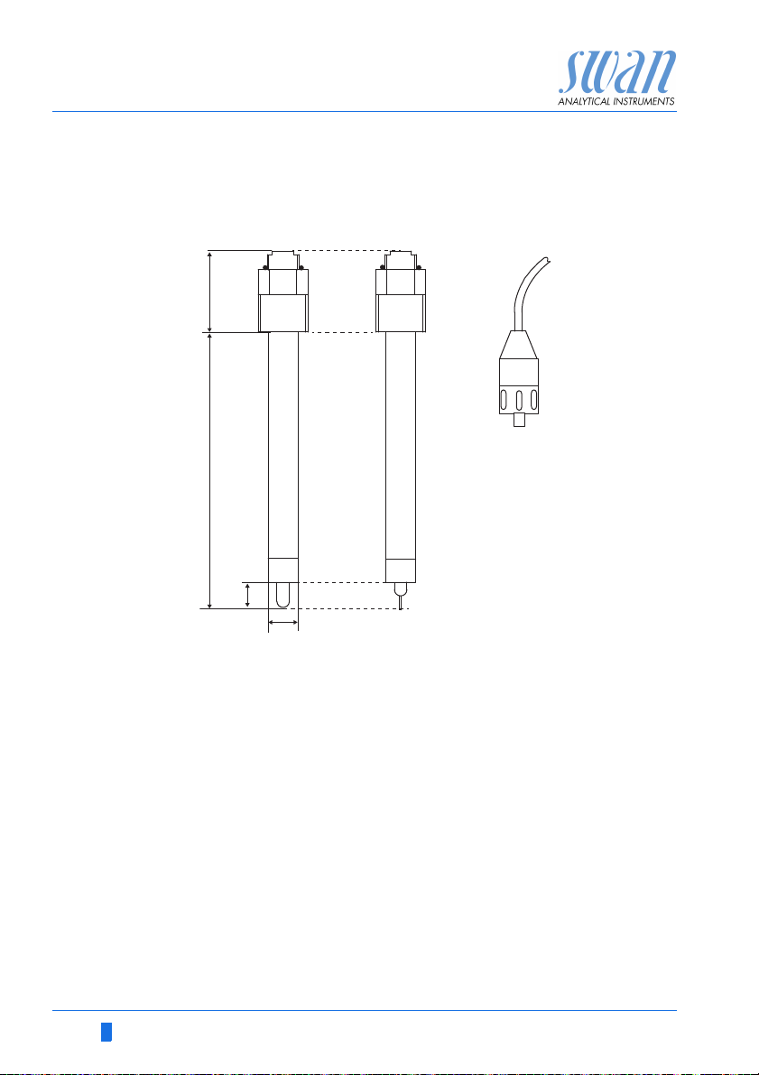
2.2.8 Swansensor pH and Redox FL
pH/Redox electrode for the measurement of pH value or redox potential in high purity water. Only in combination with Swansensor
Reference FL.
pH-Sensor ORP Sensor Sensor cable with plug
Specifications
pH-Sensor
Specifications
Redox-Sensor
Operative and measuring range:
Reference electrode:
Operating temperature:
Pressure:
Conductivity measuring medium:
Connection:
Operative and measuring range:
Reference electrode:
Operating temperature:
Pressure:
Conductivity measuring medium:
Connection:
1 to 12 pH
Reference FL
0–50 °C
pressure free
min. 0.055 µS/cm
plug PG 13.5
-500 to +1500 mV
Reference FL
0–50 °C
pressure free
min. 0.055 µS/cm
plug PG 13.5
20 A-96.250.441 / 060619
AMU pH-Redox
12
75
110
184
Product Description
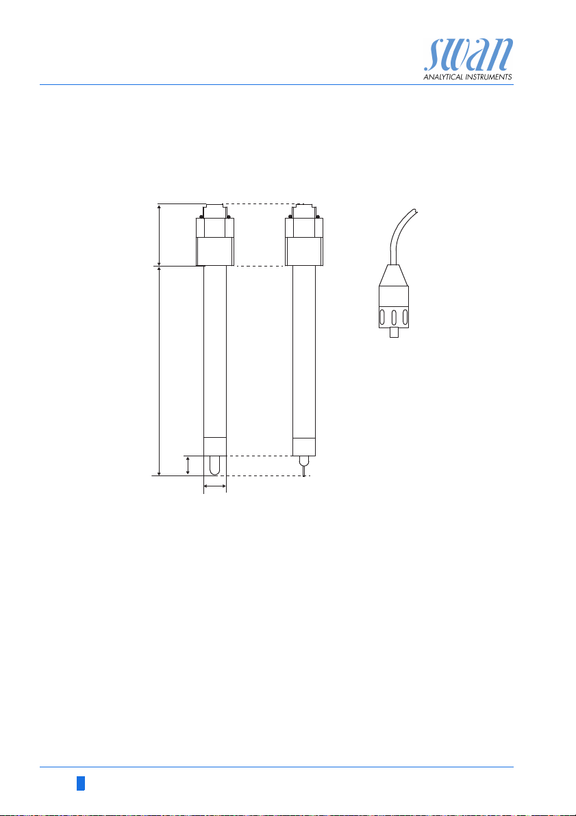
2.2.9 Swansensor Reference FL
Reference electrode for Swansensor pH FL or Swansensor Redox
FL.
Specifications Reference system:
Electrolyte:
Operating temperature:
Pressure:
Min. Conductivity:
Connection:
Ag/AgCl
KCl, 3.5 M
0–50 °C
pressure free
min. 0.055 µS/cm
plug PG 13.5
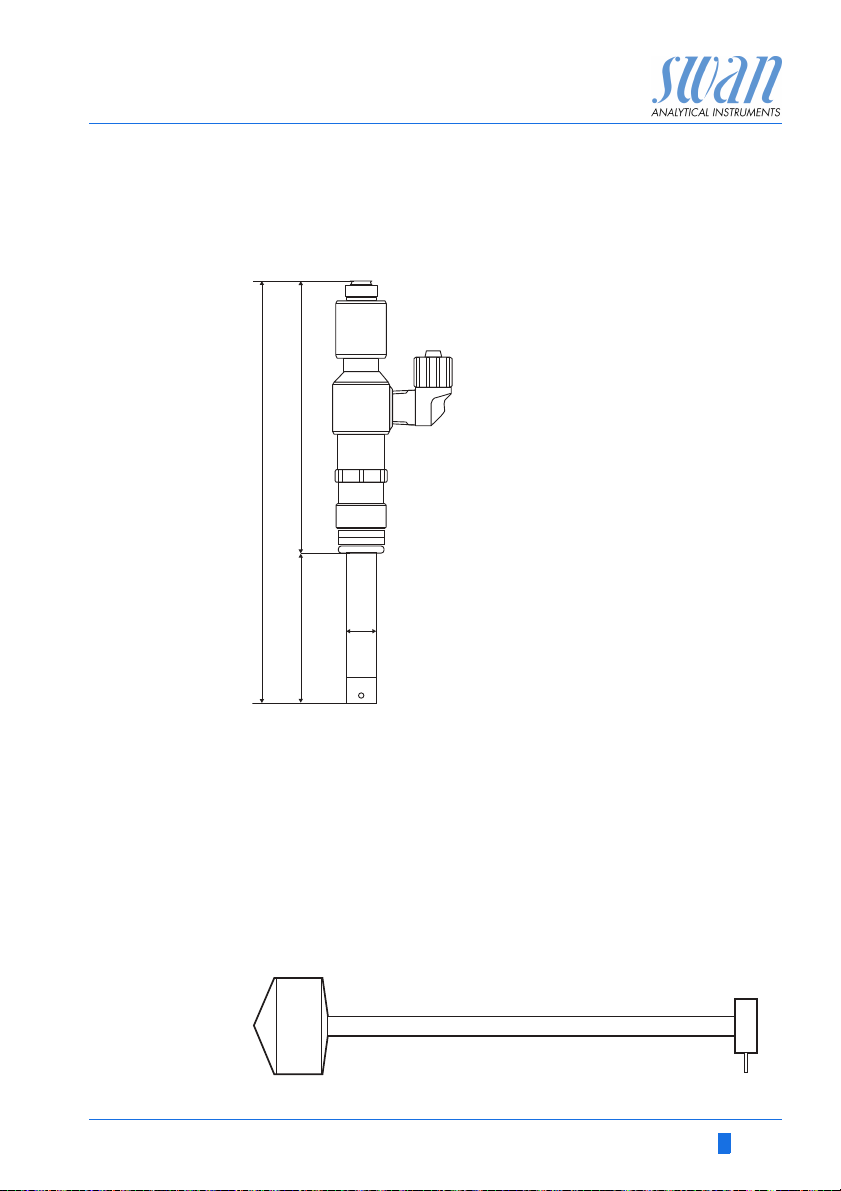
2.2.10 Spray Nozzle
For automatic cleaning of the sensor tips applicable with flow cell
M-Flow 10-3PG.
A-96.250.441 / 060619 21
AMU pH-Redox
Installation
3. Installation
3.1. Installation Checklist Monitors
Check Instrument’s specification must conform to your power ratings.
Do not switch on power until all external devices are connected.
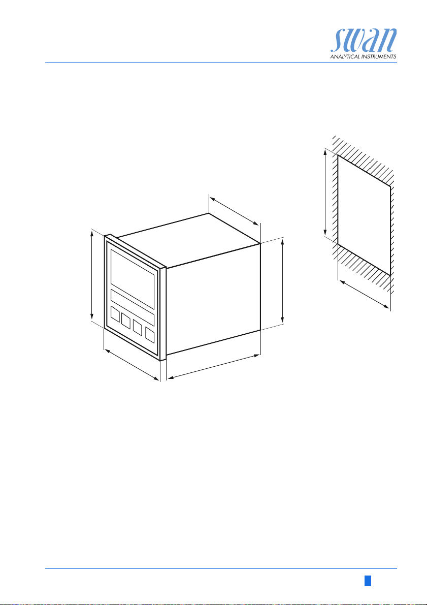
Installation The transmitter is intended for panel mounting. The dimensions
are shown in Dimensions of the AMU Transmitter, p. 23.
Electrical Connections
pH/ORP
sensor
Power-up Turn on the sample flow and wait until the flow cell is completely
Instrument
set-up
Run-in period Let the instrument run continuously for 1 h.
pH sensor
calibration
ORP sensor
calibration
Connect all external devices, see Electrical Connections, p. 32.
Connect the power cord, but do not switch on power until all
external devices are connected.
Install the sensors, see Flow Cell QV-Flow, p. 25 or Flow Cell M-
Flow, p. 28.
Connect the sensor cables.
Store the protective caps for later use.
filled.
Switch on power.
First, the transmitter performs a self test, displays the firmware
version and then starts normal operation.
Adjust sample flow. Program all parameters for sensor and
external devices (interface, recorders, etc.). Program all parameters for instrument operation (limits, alarms).
Perform standard calibration or process calibration according to
Calibration, p. 48.
Perform standard calibration or process calibration according to
Calibration, p. 48.
22 A-96.250.441 / 060619
AMU pH-Redox
96 mm
89.8 mm
89.8 mm
112 m m
7 mm
96 mm
92 mm
92 mm
Installation
3.2. Dimensions of the AMU Transmitter
A-96.250.441 / 060619 23
AMU pH-Redox
ABC D
AB
Installation
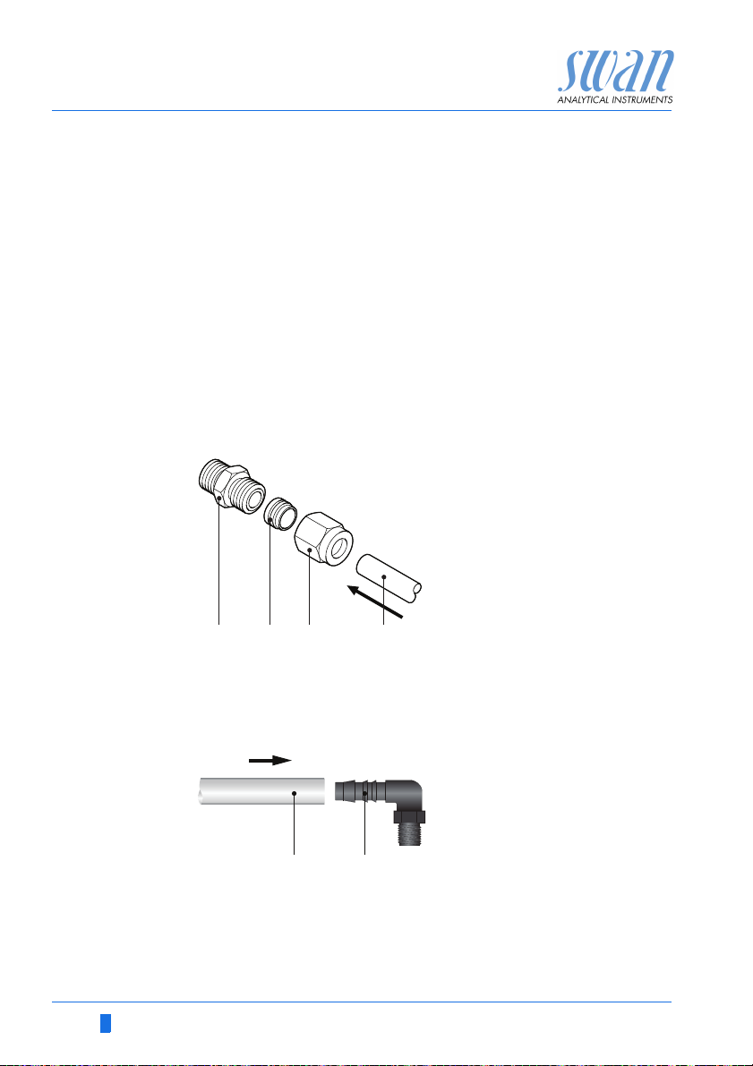
3.3. Connecting Sample Inlet and Outlet
3.3.1 Serto Fitting Stainless Steel for QV-Flow Cell
Preparation Cut the tube to length and deburr it. The tube must be straight and
free from blemishes for approximately 1,5 x tube diameter from the
end.
Lubrication with lubricating oil, MoS2, Teflon etc. is recommended
for the assembly and reassembly of bigger sized unions (thread,
compression ferrule).
Installation 1 Screw on the union nut by hand until finger tight. At the same
time, push the tube against the body.
2 Tighten down the union nut 1¾ rotation using an open ended
spanner. Hold Body from turning with a second wrench.
A
Body
B
Compression ferrule
C
Union nut
D
Tube
3.3.2 Elbow Hose Nozzle for M-Flow Cell
Use plastic tube (FEP, PA, or PE 10 x 12 mm) to connect the sample inlet and outlet.
ABPlastic tube 10 x 12
Elbow hose nozzle
24 A-96.250.441 / 060619
AMU pH-Redox
A
B
C
Installation
3.4. Flow Cell QV-Flow
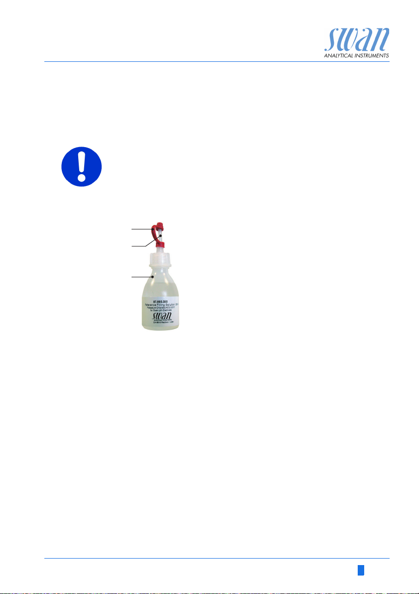
3.4.1 Install Swansensor pH or Redox SI
CAUTION
Fragile parts
The pH and ORP sensors are fragile.
Handle with care.
Do not spill KCl when removing the protective cap.
Prepare the
KCl Bottle
A
Seal cap
B
Dosing tip
C
KCl bottle
1 Remove the seal cap [A] from the dosing tip [B].
2 Cut off the upper sealed part of the dosing tip.
A-96.250.441 / 060619 25
 Loading...