

Swann AMI Trides Operator's Manual
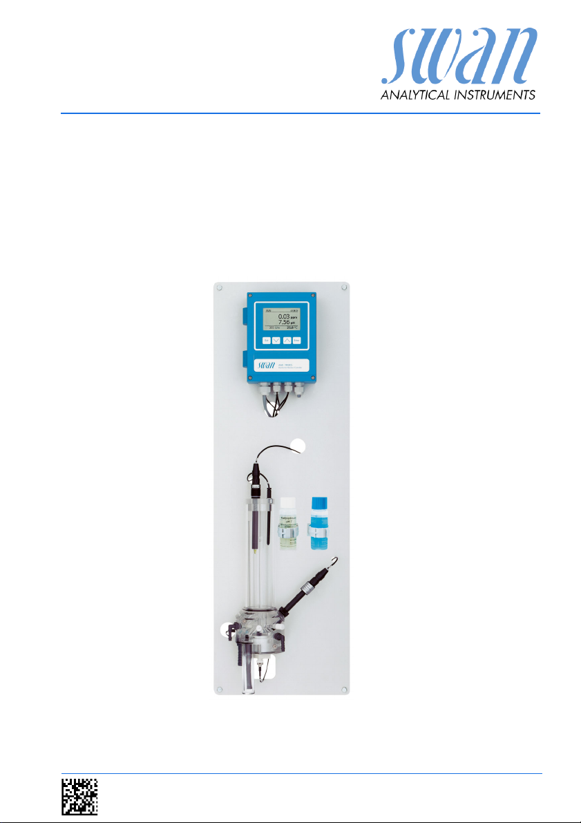
AMI Trides
Version 6.20 and higher
s Manual
Operator’
A-96.250.111 / 211019

Customer Support
SWAN and its representatives maintain a fully trained staff of technical specialists
around the world. For any technical question, contact your nearest
SWAN representative, or the manufacturer:
SWAN ANALYTISCHE INSTRUMENTE AG
Studbachstrasse 13
8340 Hinwil
Switzerland
Internet: www.swan.ch
E-mail: support@swan.ch
Document Status
Title:
ID:
AMI Trides Operator’s Manual
A-96.250.111
Revision Issue
00 Sept. 2004 First Edition
01 Sept. 2006 ---------
02 Nov. 2012 Improved troubleshooting, general update accord-
ing to new firmware release.
03 April 2016 Update to FW Release 6.00, Mainboard Rev. 2.5
© 2016, SWAN ANALYTISCHE INSTRUMENTE AG, Switzerland, all rights reserved
subject to change without notice

AMI Trides
Table of Contents
1. Safety Instructions . . . . . . . . . . . . . . . . . . . . . . . . . . . . . . . . . . . 4
1.1. Warning Notices . . . . . . . . . . . . . . . . . . . . . . . . . . . . . . . . . . . . . . 4
1.2. General Safety Regulations . . . . . . . . . . . . . . . . . . . . . . . . . . . . . 6
1.3. Restriction for use. . . . . . . . . . . . . . . . . . . . . . . . . . . . . . . . . . . . . 7
2. Product Description . . . . . . . . . . . . . . . . . . . . . . . . . . . . . . . . . . 9
2.1. Description of the System. . . . . . . . . . . . . . . . . . . . . . . . . . . . . . . 9
2.2. Instrument Specification . . . . . . . . . . . . . . . . . . . . . . . . . . . . . . . . 14
2.3. Instrument Overview. . . . . . . . . . . . . . . . . . . . . . . . . . . . . . . . . . . 17
3. Installation. . . . . . . . . . . . . . . . . . . . . . . . . . . . . . . . . . . . . . . . . . 18
3.1. Installation Checklist Monitors . . . . . . . . . . . . . . . . . . . . . . . . . . . 18
3.2. Mounting of Instrument Panel. . . . . . . . . . . . . . . . . . . . . . . . . . . . 19
3.3. Connecting Sample and Waste . . . . . . . . . . . . . . . . . . . . . . . . . . 19
3.4. Install the Reference Electrode . . . . . . . . . . . . . . . . . . . . . . . . . . 20
3.5. Install the Temperature Sensor . . . . . . . . . . . . . . . . . . . . . . . . . . 21
3.6. Install the Optional pH or Redox Electrode . . . . . . . . . . . . . . . . . 21
3.6.1 Install the pH or Redox Electrode into the Flow Cell . . . . . . . . . 22
3.6.2 Connect the pH Electrode to the Transmitter . . . . . . . . . . . . . . 23
3.6.3 Firmware Settings for pH/ Redox Electrode . . . . . . . . . . . . . . . 24
3.7. Electrical Connections . . . . . . . . . . . . . . . . . . . . . . . . . . . . . . . . . 25
3.8. Connection Diagram. . . . . . . . . . . . . . . . . . . . . . . . . . . . . . . . . . . 27
3.9. Power Supply . . . . . . . . . . . . . . . . . . . . . . . . . . . . . . . . . . . . . . . . 28
3.10. Input . . . . . . . . . . . . . . . . . . . . . . . . . . . . . . . . . . . . . . . . . . . . . . . 29
3.11. Relay Contacts . . . . . . . . . . . . . . . . . . . . . . . . . . . . . . . . . . . . . . . 29
3.11.1 Alarm Relay. . . . . . . . . . . . . . . . . . . . . . . . . . . . . . . . . . . . . . . . 29
3.11.2 Relay 1 and 2 . . . . . . . . . . . . . . . . . . . . . . . . . . . . . . . . . . . . . . 30
3.12. Signal Outputs . . . . . . . . . . . . . . . . . . . . . . . . . . . . . . . . . . . . . . . 32
3.12.1 Signal Output 1 and 2 (current outputs) . . . . . . . . . . . . . . . . . . 32
3.13. Interface Options . . . . . . . . . . . . . . . . . . . . . . . . . . . . . . . . . . . . . 32
3.13.1 Signal Output 3 . . . . . . . . . . . . . . . . . . . . . . . . . . . . . . . . . . . . . 33
3.13.2 Profibus, Modbus Interface . . . . . . . . . . . . . . . . . . . . . . . . . . . . 33
3.13.3 HART Interface . . . . . . . . . . . . . . . . . . . . . . . . . . . . . . . . . . . . . 34
3.13.4 USB Interface . . . . . . . . . . . . . . . . . . . . . . . . . . . . . . . . . . . . . . 34
4. Instrument Setup . . . . . . . . . . . . . . . . . . . . . . . . . . . . . . . . . . . . 35
4.1. Establish sample flow . . . . . . . . . . . . . . . . . . . . . . . . . . . . . . . . . . 35
4.2. Programming . . . . . . . . . . . . . . . . . . . . . . . . . . . . . . . . . . . . . . . . 35
4.3. Calibration of pH electrode . . . . . . . . . . . . . . . . . . . . . . . . . . . . . . 35
4.4. Correction of Trides sensor . . . . . . . . . . . . . . . . . . . . . . . . . . . . . 36
A-96.250.111 / 211019 1

AMI Trides
5. Operation. . . . . . . . . . . . . . . . . . . . . . . . . . . . . . . . . . . . . . . . . . . 37
5.1. Keys . . . . . . . . . . . . . . . . . . . . . . . . . . . . . . . . . . . . . . . . . . . . . . . 37
5.2. Display . . . . . . . . . . . . . . . . . . . . . . . . . . . . . . . . . . . . . . . . . . . . . 38
5.3. Software Structure . . . . . . . . . . . . . . . . . . . . . . . . . . . . . . . . . . . . 39
5.4. Changing Parameters and values. . . . . . . . . . . . . . . . . . . . . . . . . 40
6. Maintenance . . . . . . . . . . . . . . . . . . . . . . . . . . . . . . . . . . . . . . . . 41
6.1. Maintenance Schedule . . . . . . . . . . . . . . . . . . . . . . . . . . . . . . . . . 41
6.2. Cleaning of Trides protective filter . . . . . . . . . . . . . . . . . . . . . . . . 43
6.3. Cleaning of Trides sensor. . . . . . . . . . . . . . . . . . . . . . . . . . . . . . . 44
6.4. Cleaning of Reference Electrode . . . . . . . . . . . . . . . . . . . . . . . . . 46
6.5. Cleaning of pH Electrode . . . . . . . . . . . . . . . . . . . . . . . . . . . . . . . 47
6.6. Cleaning of Flow Cell . . . . . . . . . . . . . . . . . . . . . . . . . . . . . . . . . . 48
6.7. Calibration of Trides Sensor . . . . . . . . . . . . . . . . . . . . . . . . . . . . . 50
6.7.1 Process pH . . . . . . . . . . . . . . . . . . . . . . . . . . . . . . . . . . . . . . . . 50
6.7.2 Standard pH . . . . . . . . . . . . . . . . . . . . . . . . . . . . . . . . . . . . . . . 51
6.7.3 Standard Redox. . . . . . . . . . . . . . . . . . . . . . . . . . . . . . . . . . . . . 52
6.7.4 Zero Trides . . . . . . . . . . . . . . . . . . . . . . . . . . . . . . . . . . . . . . . . 52
6.7.5 Process Trides. . . . . . . . . . . . . . . . . . . . . . . . . . . . . . . . . . . . . . 52
6.8. Replacing Fuses . . . . . . . . . . . . . . . . . . . . . . . . . . . . . . . . . . . . . . 54
6.9. Longer Stop of Operation . . . . . . . . . . . . . . . . . . . . . . . . . . . . . . . 55
7. Troubleshooting . . . . . . . . . . . . . . . . . . . . . . . . . . . . . . . . . . . . . 56
7.1. Diagnostic Values . . . . . . . . . . . . . . . . . . . . . . . . . . . . . . . . . . . . . 56
7.2. Troubleshooting List . . . . . . . . . . . . . . . . . . . . . . . . . . . . . . . . . . . 56
7.3. Error List . . . . . . . . . . . . . . . . . . . . . . . . . . . . . . . . . . . . . . . . . . . . 58
8. Program Overview . . . . . . . . . . . . . . . . . . . . . . . . . . . . . . . . . . . 62
8.1. Messages (Main Menu 1) . . . . . . . . . . . . . . . . . . . . . . . . . . . . . . . 62
8.2. Diagnostics (Main Menu 2) . . . . . . . . . . . . . . . . . . . . . . . . . . . . . . 62
8.3. Maintenance (Main Menu 3) . . . . . . . . . . . . . . . . . . . . . . . . . . . . . 63
8.4. Operation (Main Menu 4) . . . . . . . . . . . . . . . . . . . . . . . . . . . . . . . 64
8.5. Installation (Main Menu 5). . . . . . . . . . . . . . . . . . . . . . . . . . . . . . . 65
9. Program List and Explanations. . . . . . . . . . . . . . . . . . . . . . . . . 67
1 Messages. . . . . . . . . . . . . . . . . . . . . . . . . . . . . . . . . . . . . . . . . . 67
2 Diagnostics . . . . . . . . . . . . . . . . . . . . . . . . . . . . . . . . . . . . . . . . 67
3 Maintenance . . . . . . . . . . . . . . . . . . . . . . . . . . . . . . . . . . . . . . . 69
4 Operation . . . . . . . . . . . . . . . . . . . . . . . . . . . . . . . . . . . . . . . . . . 70
5 Installation . . . . . . . . . . . . . . . . . . . . . . . . . . . . . . . . . . . . . . . . . 71
10. Material Safety Data sheets . . . . . . . . . . . . . . . . . . . . . . . . . . . . 86
10.1. Reagents. . . . . . . . . . . . . . . . . . . . . . . . . . . . . . . . . . . . . . . . . . . . 86
2 A-96.250.111 / 211019

AMI Trides
11. Default Values . . . . . . . . . . . . . . . . . . . . . . . . . . . . . . . . . . . . . . . 87
12. Index . . . . . . . . . . . . . . . . . . . . . . . . . . . . . . . . . . . . . . . . . . . . . . 90
13. Notes . . . . . . . . . . . . . . . . . . . . . . . . . . . . . . . . . . . . . . . . . . . . . . 92
A-96.250.111 / 211019 3

AMI Trides
Safety Instructions
AMI Trides–Operator’s Manual
This document describes the main steps for instrument setup, operation and maintenance.
1. Safety Instructions
General The instructions included in this section explain the potential risks
associated with instrument operation and provide important safety
practices designed to minimize these risks.
If you carefully follow the information contained in this section, you
can protect yourself from hazards and create a safer work environment.
More safety instructions are given throughout this manual, at the
respective locations where observation is most important. Strictly
follow all safety instructions in this publication.
Target
audience
OM Location Keep the AMI Operator’s Manual in proximity of the instrument.
Qualification,
Training
Operator: Qualified person who uses the equipment for its intended
purpose.
Instrument operation requires thorough knowledge of applications,
instrument functions and software program as well as all applicable
safety rules and regulations.
To be qualified for instrument installation and operation, you must:
read and understand the instructions in this manual as well as
the Material Safety Data Sheets.
know the relevant safety rules and regulations.
The symbols used for safety-related notices have the following significance:
4 A-96.250.111 / 211019
AMI Trides
Safety Instructions
1.1. Warning Notices
The symbols used for safety-related notices have the following significance:
DANGER
Your life or physical wellbeing are in serious danger if such
warnings are ignored.
Follow the prevention instructions carefully.
WARNING
Severe injuries or damage to the equipment can occur if such
warnings are ignored.
Follow the prevention instructions carefully.
CAUTION
Damage to the equipment, minor injury, malfunctions or incorrect process can be the consequence if such warnings are ignored.
Follow the prevention instructions carefully.
Mandatory
Signs
A-96.250.111 / 211019 5
The importance of the mandatory signs in this manual.
Safety goggles
Safety gloves
AMI Trides
Safety Instructions
Warning Signs The importance of the warning signs in this manual.
Electrical shock hazard
Corrosive
Harmful to health
Flammable
Warning general
Attention general
1.2. General Safety Regulations
Legal
Requirements
Spare Parts
and
Disposables
The user is responsible for proper system operation.
All precautions must be followed to ensure safe operation
of the instrument.
Use only official SWAN spare parts and disposables. If other parts
are used during the normal warranty period, the manufacturer’s
warranty is voided.
6 A-96.250.111 / 211019
AMI Trides
Safety Instructions
Modifications Modifications and instrument upgrades shall only be carried out by
an authorized Service Technician. SWAN will not accept responsibility for any claim resulting from unauthorized modification or alteration.
WARNING
Electrical Shock Hazard
If proper operation is no longer possible, the instrument must be
disconnected from all power lines, and measures must be taken
to prevent inadvertent operation.
To prevent from electrical shock, always make sure that the
ground wire is connected.
Service shall be performed by authorized personnel only.
Whenever electronic service is required, disconnect instru-
ment power and power of devices connected to.
– relay 1,
– relay 2,
– alarm relay
WARNING
For safe instrument installation and operation you must read
and understand the instructions in this manual.
WARNING
Only SWAN trained and authorized personnel shall perform the
tasks described in this document.
A-96.250.111 / 211019 7

AMI Trides
Safety Instructions
1.3. Restriction for use
Sample
requirements
Dechlorination After Dechlorination the disinfectant value is always (near) zero: To
Mixture of
several
disinfectants
Reagents Calibration Solution pH 4
Download
MSDS
Addition or presence of disinfectants containing stabilizers like cyanuric acid or 5,5-Dimethylhydantoin or organic chlorine compounds perturb the measurement. A controlled dosing system
depending on chlorine surplus cannot operate with these products.
Cleaner and corrosion preventives (phosphates) may perturb the
measurement.
Do not use copper tubes in the water treatment area. Copper perturbs the sensor system.
No sand (or other polishing material) or oil are allowed in the sample.
prevent biological growth, we strongly recommend to flush the flow
cell and sensor occasionally with water of higher disinfectant concentration, e.g. by switching to a sample line before dechlorination.
To do a sensible correction, a certain amount of chlorine is required, which may not be available during normal operation.
The Trides always measures the total of all added disinfectants.
Separation measurements are not possible.
Calibration Solution pH 7
Calibration Solution pH 9
The current Material Safety Data Sheets (MSDS) for the above listed Reagents are available for downloading at www.swan.ch.
8 A-96.250.111 / 211019

AMI Trides
Product Description
2. Product Description
2.1. Description of the System
Application
Range
The AMI Trides is used to measure and control in potable water,
sanitary water and swimming pools the following disinfectants:
Hypochlorous acid
Free chlorine
Ozone
Chlorine-dioxide
Bromine
Iodine
There are two main applications:
1 Control of set-point
The instrument is used to measure and maintain a certain disinfectant value in the system. The disinfectant is added with a dosing
unit.
2 Dechlorination
The disinfectant is removed to protect a device, which is sensitive
to disinfectants, e.g. a reverse osmosis. The instrument detects the
remaining disinfectant level after dechlorination and superintends
that the disinfectant concentration does not exceed the max. limit
value. Otherwise a warning is issued.
Signal
Outputs
Relays Two potential-free contacts programmable as limit switches for
Two signal outputs programmable for measured values (freely scalable, linear, bilinear, log) or as continuous control output (control
parameters programmable).
Current loop: 0/4–20 mA
Maximal burden: 510 Ω
Third signal output available as an option. The third signal output
can be operated as a current source or as a current sink (selectable
via switch).
measuring values, controllers or timer for system cleaning with automatic hold function.
Maximum load: 1 A/ 250 VAC
A-96.250.111 / 211019 9

AMI Trides
Product Description
Alarm Relay One potential free contact.
Alternatively:
Open during normal operation, closed on error and loss of
power.
Closed during normal operation, open on error and loss of
power.
Summary alarm indication for programmable alarm values and instrument faults.
Input For potential-free contact to freeze the measuring value or to inter-
rupt control in automated installations (hold function or remote-off).
Communica-
tion interface
(optional)
Safety
Features
Option
pH or Redox
Display Selectable measuring unit as ppm or mg/l.
USB Interface for logger download
Third signal output (can be used in parallel to the USB interface)
RS485 with Fieldbus protocol Modbus or Profibus DP
HART interface
No data loss after power failure. All data is saved in non-volatile
memory.
Over voltage protection of in- and outputs.
Galvanic separation of measuring inputs and signal outputs.
An optional pH/Redox electrode can be installed. Temperature
compensation of pH is done automatically.
10 A-96.250.111 / 211019
AMI Trides
100
y
1
a
1
a
2
90
80
70
60
50
40
30
20
10
567 8 910
pH
0
100
y
2
90
80
70
60
50
40
30
20
10
0
Product Description
Measuring
principle
About free
chlorine
3-electrode amperometry:
The sensor consists of two platinum electrodes and a reference
electrode. A voltage is applied between the measuring electrode
(platinum rod) and the counter electrode (platinum ring) of the trides sensor. The disinfectant in the sample generates a small current between the electrodes, which is proportional to the
disinfectant concentration. The reference electrode controls the
voltage and guarantees optimal measuring conditions on the platinum sensor.
For optimal sensitivity, a rotor continuously cleans the surfaces of
the platinum electrodes (hydrodynamic cleaning). A Hall-effect sensor measures the rotations of the rotor to detect if there is sufficient
flow.
The signal of amperometric systems depends on flow. The flow cell
with constant head excludes all flow effects if the sample always
overflows into the longer constant head tube.
Temperature compensation is done automatically.
If chlorine is dissolved in water, it decomposes into hypochlorous
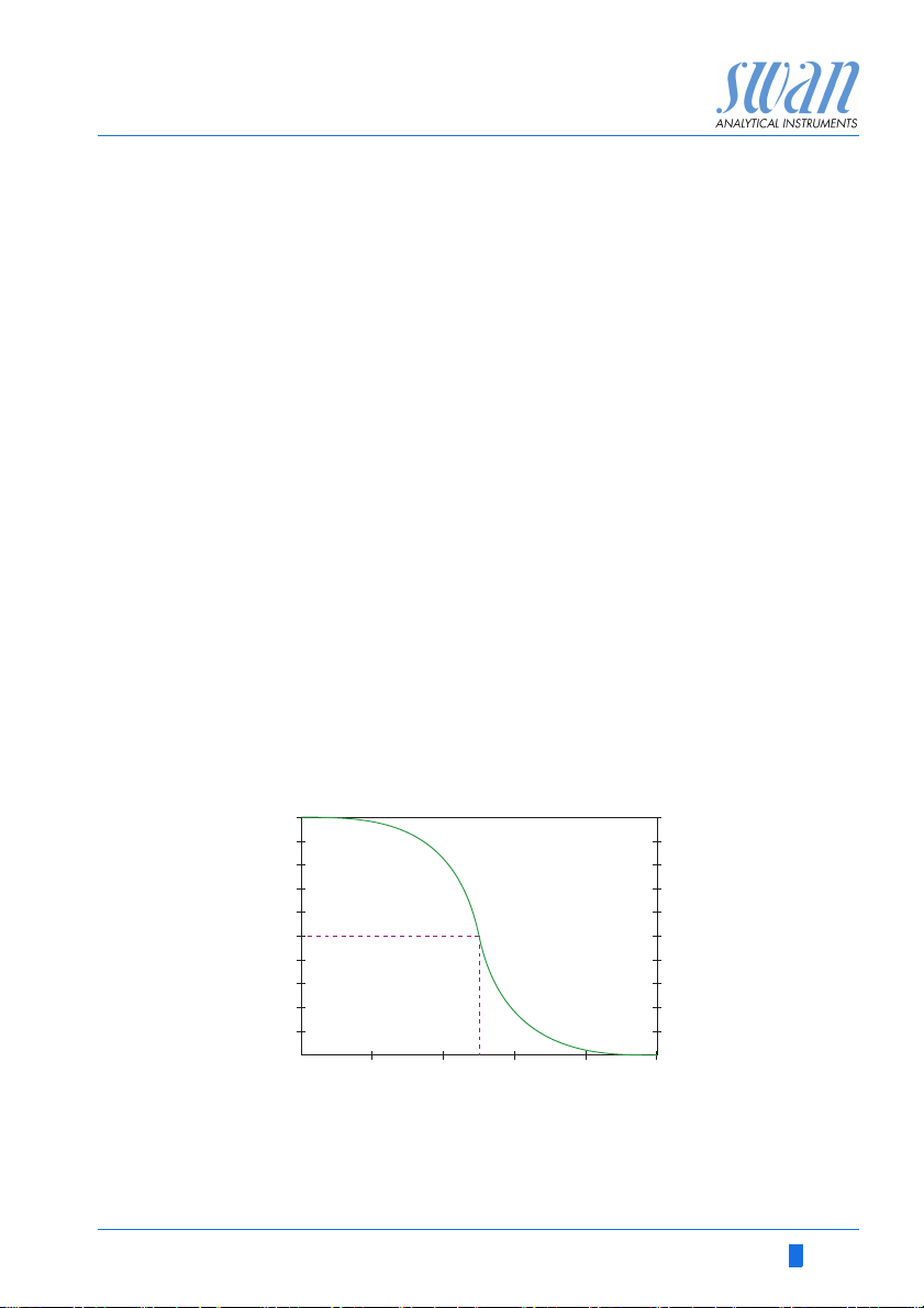
acid and hypochlorite. Free chlorine = hypochlorous acid + hypochlorite. The ratio depends on the pH value.
At pH 7: 77% hypochlorous acid, 23% hypochlorite
At pH 8: 25% hypochlorous acid, 75% hypochlorite
The hypochlorous acid is a much better disinfectant than hypochlorite. This means the efficiency of disinfection depends on pH value.
A-96.250.111 / 211019 11
y
1
y
2
a
, a2Sensitivity of electrochemical measurement in %
1
The DPD test always indicates free chlorine.
% HOCL (hypochlorous acid)
% Disinfection

AMI Trides
Product Description
Hypochlorous
acid
Free Chlorine
+ HOCl
Amperometric sensors measure mainly the hypochlorous acid.
Therefore, the higher the pH value is, the lower the current of the
sensor.
A pH compensation of the sensor signal is necessary to be able to
compare the value directly to the DPD method. For that select
<Free chlorine> in menu 5.1.3 <Installation / Sensors /Disinf.> The
pH must be measured by an optional pH electrode or be programmed correctly.
If hypochlorous acid is chosen as disinfectant in 5.1.3, the pH compensation is switched off. The displayed values show the efficiency
of disinfection. Only during correction, the value is shown as free
chlorine and can be therefore directly compared to the manual DPD
value.
If you program Free+HOCl (HOCl=hypochlorous acid) as disinfectant in 5.1.3 you can set the hypochlorous acid as parameter on the
signal outputs. The displayed value will be free chlorine.
On-line
operation
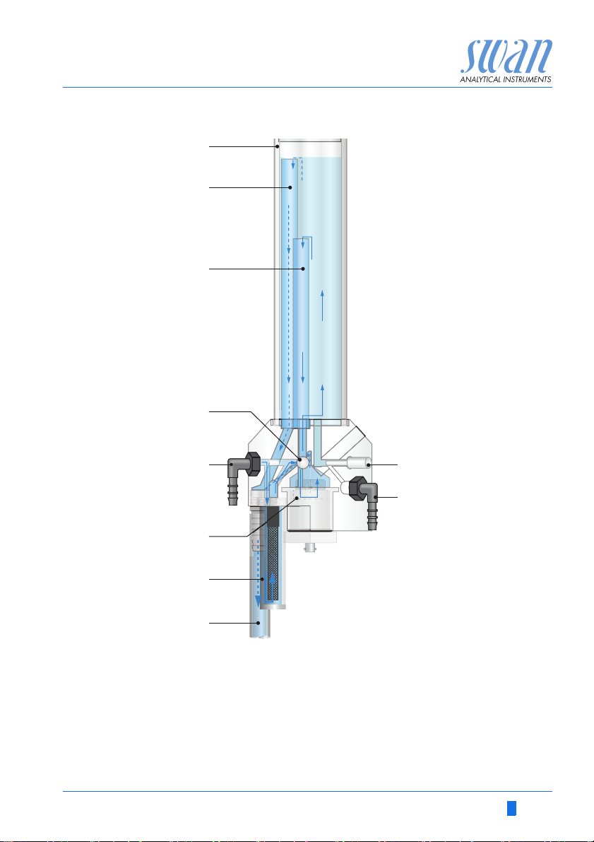
Grab sample The grab sample outlet is used to take sample from the Trides con-
The sample enters at the sample inlet [E]. It passes the filter vessel
[G] and the flow regulating valve [D], where the sample flow is adjusted, and fills the constant head [A]. Sample must always overflow via the overflow tube [B] into the waste to ensure constant
pressure at the Trides sensor [F].
A part of the sample flows through the overflow tube [C] to the Trides sensor [F], turns the rotor and leaves via sample outlet [H] into
the waste. The rotation of the rotor is detected with a Hall-effect
sensor to assure the sufficient sample flow. An inconsistent sample
flow causes the rotor to turn slowly (or stop) and produces a system
error.
stant head. This sample is used to make a comparison measurement with an other instrument.
The standard method to correct the AMI Trides is the DPD photometric method. Use a high quality photometer to determine the reference value, e.g. Swan Chematest.
12 A-96.250.111 / 211019
AMI Trides
A
B
C
D
E
F
G
H
I
J
Product Description
Fluidics
overview
A
A-96.250.111 / 211019 13
Constant head
B
C
D
E
Overflow tube to waste
Overflow tube to sensor
Flow regulating valve
Sample inlet
F
Trides sensor
G
Filter vessel
H
Sample outlet
I
Grab sample outlet
J
Grab sample valve

AMI Trides
Product Description
2.2. Instrument Specification
Power Supply Voltage: 100–240 VAC (± 10%)
50/60 Hz (± 5%)
or 24 VDC (± 10%)
Power consumption: max. 30 VA
Sample
requirements
On-site
requirements
Water consumption: aprox. 40 l/h
Temperature: 5–45 °C (41–113 F)
Inlet pressure: 0.15–2 bar (2.2–29 PSI)
Outlet pressure: pressure free
Min. sample conductivity: 5 S/cm
no oil and no grease
The analyzer site must permit connections to:
Sample inlet: Hose nozzle R ¼” x 6 mm
Sample outlet: G ½” adapter for flexible tube
15 x 20 mm
Electronics
housing
Aluminium with a protection degree of IP 66 / NEMA 4X
Ambient temperature: - 10 to + 50 °C
Humidity: 10–90% rel., non condensing
Display: backlit LCD, 75 x 45 mm
14 A-96.250.111 / 211019
AMI Trides
Product Description
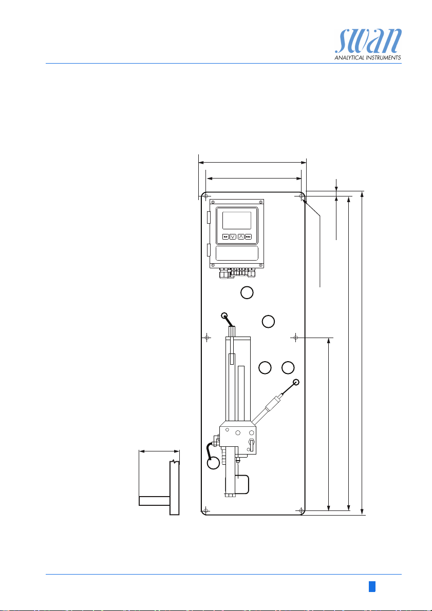
Dimensions Panel: 850x280 x 200 mm, PVC
Screws: 5 mm or 6 mm diameter
Weight: 6 kg
280 mm/ 11”
254 mm/ 10”
3
30 mm / 1 ”
/
AMI Trides
13 mm / ½”
6 x dia. 6.5 mm / ¼”
”
16
/
7
16
412 mm /16 ¼”
850 mm / 33½”
824 mm / 32
A-96.250.111 / 211019 15
AMI Trides
Product Description
Dimensions
(compact
version)
Panel: 530x300x200 mm, PVC
Screws: 5 mm or 6 mm diameter
300 mm/ 11.8”
260 mm/ 10.2”
20 mm / 0.8”
AMI Trides
490 mm / 19.3”
4 x dia. 6.5 mm / ¼”
530 mm / 20.9”
16 A-96.250.111 / 211019
AMI Trides
Product Description
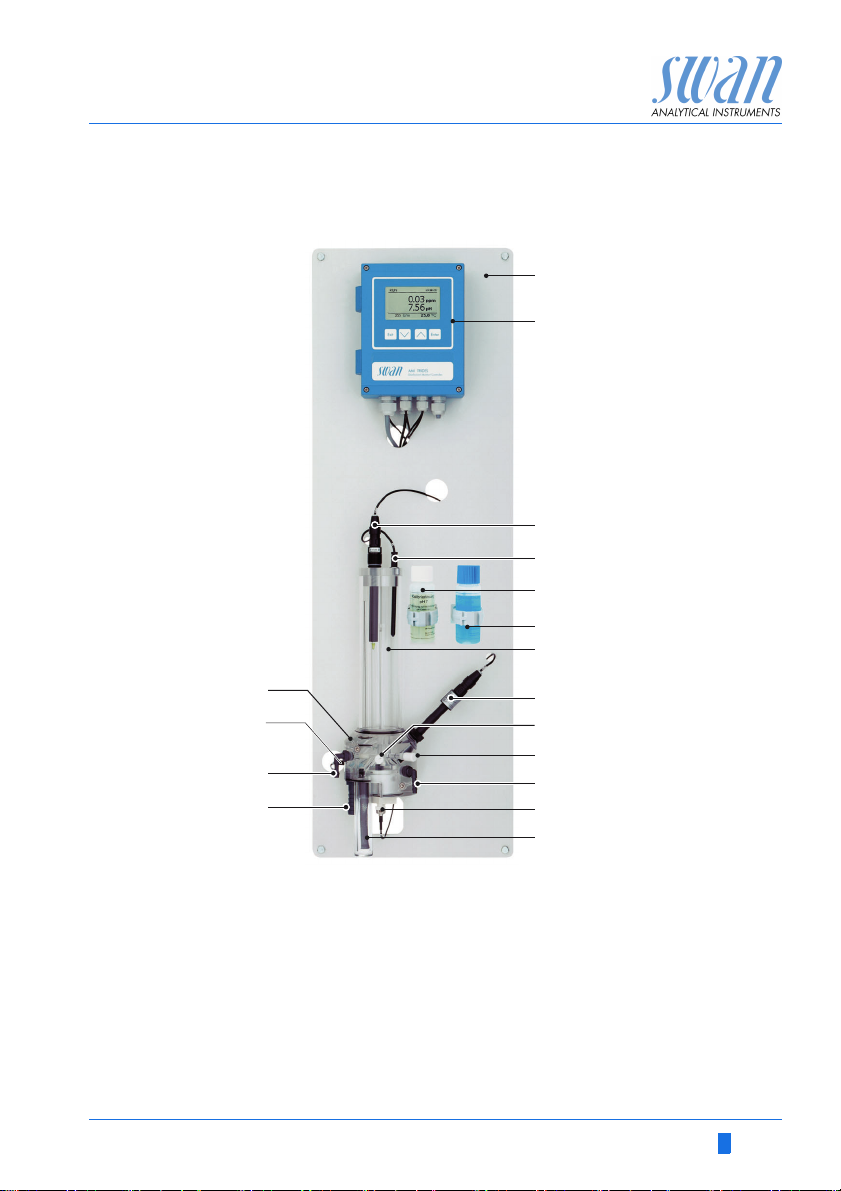
2.3. Instrument Overview
A
B
C
D
E
F
G
Q
P
O
N
A
Panel
B
Transmitter
C
pH/Redox electrode
D
Temperature sensor
E
Calibration solution pH 7
F
Calibration solution pH9
G
Constant head
H
Reference electrode
I
Flow regulating valve
A-96.250.111 / 211019 17
H
I
J
K
L
M
J
Grab sample valve
K
Grab sample outlet
L
Trides sensor
M
Filter
N
Sample outlet
O
Sample inlet
P
Hall-effect sensor
Q
Flow cell block

AMI Trides
Installation
3. Installation
3.1. Installation Checklist Monitors
Check Instrument’s specification must conform to your AC power ratings.
Do not turn on power until instructed to do so.
On-site requirements
Installation Mount the instrument in vertical position.
Electrical Wiring Connect all external devices like limit switches, current loops and
Electrodes Install the reference electrode.
Temperature
sensor
Power-up Turn on the sample flow and wait until the rotor on the Trides sen-
Instrument
set-up
pH/Redox electrode calibration
Free chlorine
> 0.1 ppm
Free chlorine
< 0.1 ppm
100–240 VAC (± 10%), 50/60 Hz (± 5%) or 24 VDC, isolated
(±10%) power outlet with ground connection and 30 VA.
Sample line with sufficient sample flow and pressure (see Instru-
ment Specification, p. 14.
Display should be at eye level.
Mount the filter, filter vessel, the long and short overflow tube, the
outer tube and constant head cover
Connect the sample and waste line.
pumps (see Connection Diagram, p. 27.)
Connect power cord; do NOT switch on power yet!
Install the pH electrode (optional).
The temperature sensor is already connected to the transmitter
and fixed to the panel with an adhesive tape.
sor starts turning.
Switch on power.
Program all parameters for sensor and external devices (interface,
recorders, etc.).
Program all parameters for instrument operation (limits, alarms).
Calibrate pH/Redox electrode if installed.
Let instrument operate 24 h without interruption at normal sample
conditions. Then correct disinfection value if necessary.
Let instrument operate at least 5 days without interruption at
normal sample conditions. Make zero point calibration. Correct
disinfection value if necessary.
18 A-96.250.111 / 211019

AMI Trides
A
B
C
D
Installation
3.2. Mounting of Instrument Panel
Mounting re-
quirements
3.3. Connecting Sample and Waste
The first part of this chapter describes the preparing and placing of
the system for use.
The instrument must only be installed by trained personnel.
Mount the instrument in vertical position.
For ease of operation mount it so that the display is at eye
level.
For the installation a kit containing the following installation
material is available:
– 6 Screws 6 x 60 mm
– 6 Dowels
– 6 Washers 6.4/ 12 mm
The instrument is only intended for indoor installation.
For dimensions see Dimensions, p. 15.
Sample inlet Push the 6x9 plastic tube [C] over the elbow hose nozzle [A] at the
Waste Connect the 1/2” tube [D] to the waste nozzle [B] and place it into
A-96.250.111 / 211019 19
sample inlet.
the atmospheric drain.
A
Elbow hose nozzle at
sample inlet
B
Sample outlet
C
Plastic tube 6x9
D
1/2” tube
AMI Trides
C
B
D
E
A
Installation
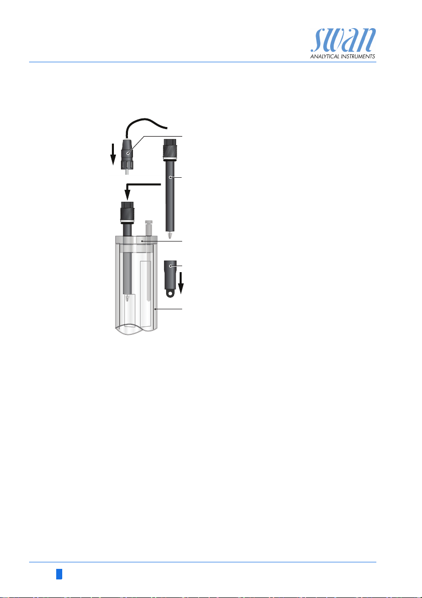
3.4. Install the Reference Electrode
The reference electrode is delivered separately and protected with
a waterfilled protective cap. The connector is fixed to the panel with
an adhesive tape and already connected to the front end PCB in
the AMI transmitter.
A
Connector
B
Protective cap
C
Reference sensor
To install the reference electrode proceed as follows:
1 Loosen the union nut [D].
2 Remove the protective cap [B] from the reference electrode [C].
3 Push the reference electrode through the union nut [D] into the
bore of the flow cell block [E] as far as it will go.
4 Tighten the union nut.
5 Remove the connector [A] from the panel and screw it onto the
reference electrode.
DEUnion nut
Flow cell block
20 A-96.250.111 / 211019
AMI Trides
A
B
C
Installation
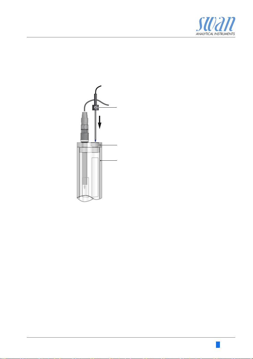
3.5. Install the Temperature Sensor
The temperature sensor is fixed to the panel with an adhesive tape
and already connected to the front end PCB in the AMI transmitter.
A
Temperature sensor
B
Constant head cover
C
Constant head
To install the temperature sensor proceed as follows:
1 Remove the temperature sensor [A] from the panel.
2 Put the temperature sensor in the designated hole of the con-
stant head cover [B].
3 Push it into the hole as far as it will go.
3.6. Install the Optional pH or Redox Electrode
The following description assumes that the installation of the pH or
redox electrode takes place after commissioning of the monitor.
A-96.250.111 / 211019 21
AMI Trides
A
B
C
D
E
Installation
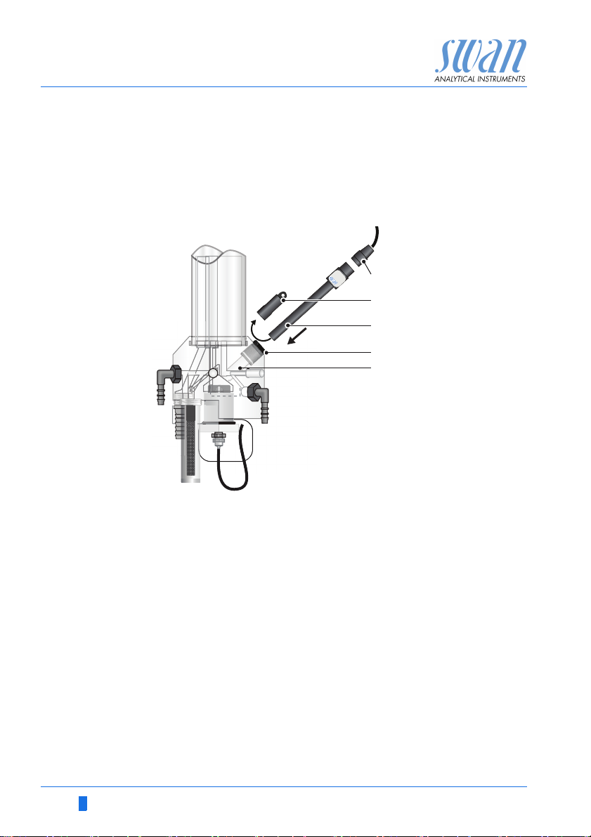
3.6.1 Install the pH or Redox Electrode into the Flow Cell
A
Connector
B
pH/Redox electrode
C
Constant head cover
D
Sensor cap
E
Constant head
1 Switch the instrument off.
2 Remove the cap [D] from the pH/redox electrode [B].
22 A-96.250.111 / 211019
3 Insert the electrode through the cover [C] into the flow cell [E]
4 Screw the connector [A] onto the sensor.
AMI Trides
A
B
C
Installation
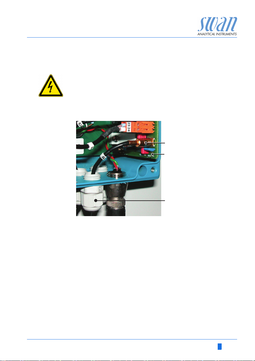
3.6.2 Connect the pH Electrode to the Transmitter
WARNING
Risk of electrical shock
Installation and maintenance of electrical parts must be performed by professionals
Always turn off AC power before manipulating electric parts.
1 Open the transmitter housing
2 Feed the cable of the electrode through one of the PG 7 cable
glands [C] into the transmitter housing.
3 Connect the coaxial plug [A] to the plug on the front end PCB
[B].
4 Close the transmitter housing.
5 Switch on the instrument.
A-96.250.111 / 211019 23

AMI Trides
5.1.1
Sensors
Type of Electrode pH
Disinf. Free chlorine
Dimension ppm
Standards
pH Electrode without
5.1.1
Sensors
Type of Electrode pH
pH Electrode without
Disinf. Free chlorine
Dimension ppm
Standards
pH Electrode
with
without
5.1.1
Sensors
Type of Electrode pH
pH Electrode without
Disinf. Free chlorine
Dimension ppm
Standards
pH Electrode
without
with
Installation
3.6.3 Firmware Settings for pH/Redox Electrode
After the pH/Redox electrode has been installed according to the
previous instructions activate the pH / Redox electrode in the menu
installation as follows:
1 Navigate to Menu <Installation>,
<Sensors>
2 Select pH Electrode.
3 Press [Enter]
<without> is highlighted.
4 Select <with>.
5 Press [Enter].
6 Press [Exit].
7 Confirm with Yes.
24 A-96.250.111 / 211019
AMI Trides
ABC
Installation
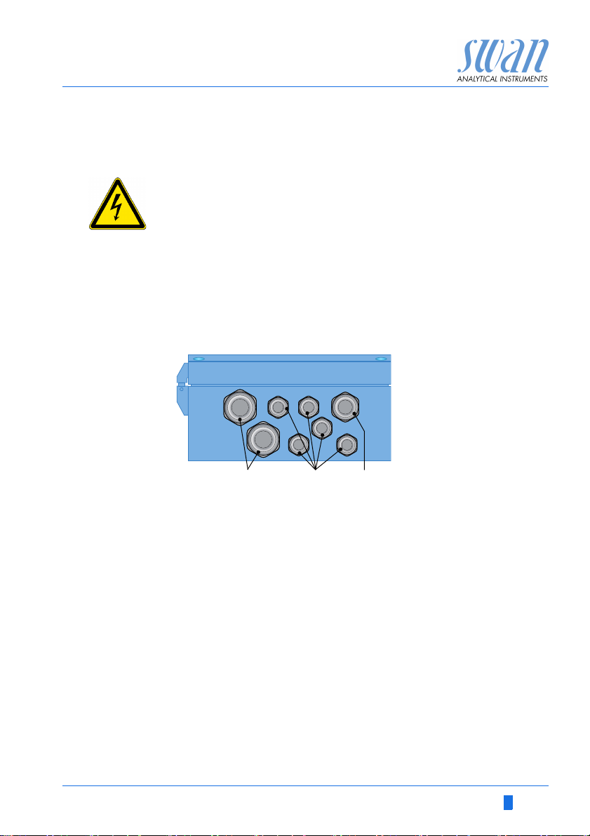
3.7. Electrical Connections
WARNING
Electrical hazard.
Always turn off AC power before manipulating electric parts.
Grounding requirements: Only operate the instrument from
an power outlet which has a ground connection.
Make sure the power specification of the instrument corre-
sponds to the power on site.
Cable
thicknesses
Wire For Power and Relays: Use max. 1.5 mm2 / AWG 14
In order to comply with IP66, use the following cable thicknesses
PG 11 cable gland: cable Ø
A
B
PG 7 cable gland: cable Ø
C
PG 9 cable gland: cable Ø
NOTICE: Protect unused cable glands
stranded wire with end sleeves.
For Signal Outputs and Input: Use 0.25 mm
stranded wire with end sleeves.
outer
3–6.5 mm
outer
4–8 mm
outer
5–10 mm
2
/ AWG 23
A-96.250.111 / 211019 25
AMI Trides
Installation
WARNING
External Voltage.
External supplied devices connected to relay 1 or 2 or to the
alarm relay can cause electrical shocks
Make sure that the devices connected to the following con-
tacts are disconnected from the power before resuming installation.
–relay 1
–relay 2
– alarm relay
WARNING
To prevent from electrical shock, do not connect the instrument
to the power unless the ground wire (PE) is connected.
Do not connect unless specifically instructed to do so.
WARNING
The mains of the AMI Transmitter must be secured by a main
switch and appropriate fuse or circuit breaker.
26 A-96.250.111 / 211019
AMI Trides
Installation
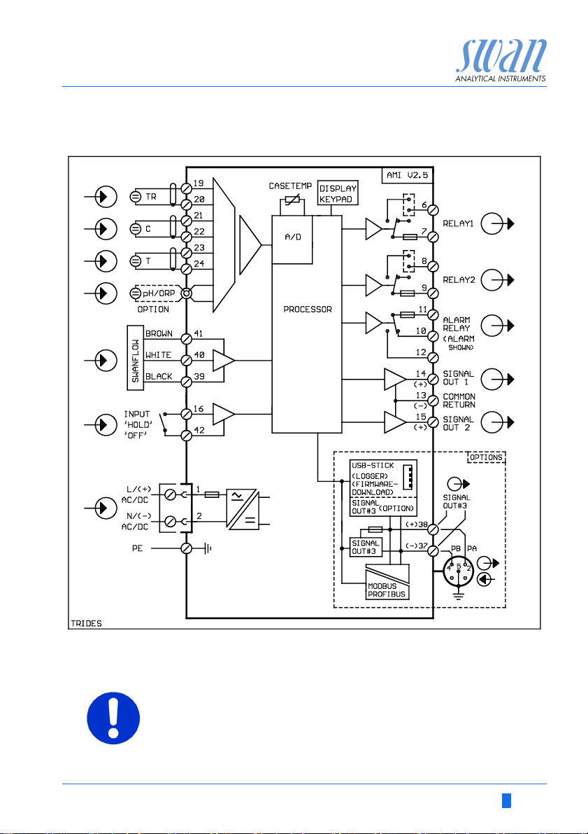
3.8. Connection Diagram
CAUTION
Use only the terminals shown in this diagram, and only for the
mentioned purpose. Use of any other terminals will cause short
circuits with possible corresponding consequences to material
and personnel.
A-96.250.111 / 211019 27
 Loading...