

Page 1
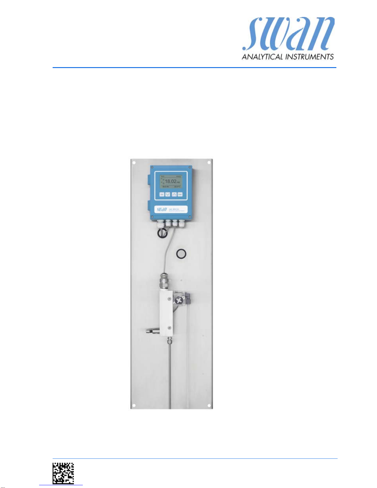
AMI Rescon
Version 6.20 and higher
A-96.250.461 / 070318
Operator’
s Manual
Page 2

© 2016, SWAN ANALYTISCHE INSTRUMENTE AG, Switzerland, all rights reserved
subject to change without notice
.
Customer Support
SWAN and its representatives maintain a fully trained staff of technical specialists
around the world. For any technical question, contact your nearest
SWAN representative, or the manufacturer:
SWAN ANALYTISCHE INSTRUMENTE AG
Studbachstrasse 13
8340 Hinwil
Switzerland
Internet: www.swan.ch
E-mail: support@swan.ch
Document Status
Title:
Monitor AMI Rescon Operator’s Manual
ID:
A-96.250.461
Revision Issue
00 Sept. 2006 First Edition
01 June 2012 Update to Rev. 4.61
02 Jan. 2015 Update to Rev. 5.30, main board V2.4
03 April 2016 Update to Rev. 6.00, main board V2.5
Page 3

AMI Rescon
A-96.250.461 / 070318 1
Table of Contents
1. Safety Instructions . . . . . . . . . . . . . . . . . . . . . . . . . . . . . . . . . . . 3
1.1. Warning Notices . . . . . . . . . . . . . . . . . . . . . . . . . . . . . . . . . . . . . . 4
1.2. General Safety Regulations . . . . . . . . . . . . . . . . . . . . . . . . . . . . . 5
1.3. Restrictions for use. . . . . . . . . . . . . . . . . . . . . . . . . . . . . . . . . . . . 6
2. Product Description . . . . . . . . . . . . . . . . . . . . . . . . . . . . . . . . . . 7
2.1. Description of the System. . . . . . . . . . . . . . . . . . . . . . . . . . . . . . . 7
2.2. Instrument Specification . . . . . . . . . . . . . . . . . . . . . . . . . . . . . . . . 10
2.3. Instrument Overview. . . . . . . . . . . . . . . . . . . . . . . . . . . . . . . . . . . 12
2.4. Single Components . . . . . . . . . . . . . . . . . . . . . . . . . . . . . . . . . . . 13
2.4.1 Transmitter AMI Rescon . . . . . . . . . . . . . . . . . . . . . . . . . . . . . . 13
2.4.2 Flow Cell QV-Flow and QV-HFlow SS316L 130 . . . . . . . . . . . . 14
2.4.3 Flow Cell B-Flow SS316L 130 . . . . . . . . . . . . . . . . . . . . . . . . . 15
2.4.4 Swansensor RC U. . . . . . . . . . . . . . . . . . . . . . . . . . . . . . . . . . . 16
3. Installation. . . . . . . . . . . . . . . . . . . . . . . . . . . . . . . . . . . . . . . . . . 17
3.1. Installation Checklist Monitors . . . . . . . . . . . . . . . . . . . . . . . . . . . 17
3.2. Mounting of Instrument Panel. . . . . . . . . . . . . . . . . . . . . . . . . . . . 18
3.3. Connecting Sample Inlet and Outlet. . . . . . . . . . . . . . . . . . . . . . . 19
3.3.1 Sample Inlet . . . . . . . . . . . . . . . . . . . . . . . . . . . . . . . . . . . . . . . 19
3.3.2 Sample Outlet . . . . . . . . . . . . . . . . . . . . . . . . . . . . . . . . . . . . . . 19
3.4. Install Sensor RCU . . . . . . . . . . . . . . . . . . . . . . . . . . . . . . . . . . . . 20
3.5. Connect the Resistivity Sensor Cable . . . . . . . . . . . . . . . . . . . . . 22
3.6. Connect the Flow Sensor Cable. . . . . . . . . . . . . . . . . . . . . . . . . . 22
3.7. Electrical Connections . . . . . . . . . . . . . . . . . . . . . . . . . . . . . . . . . 23
3.7.1 Connection Diagram . . . . . . . . . . . . . . . . . . . . . . . . . . . . . . . . . 25
3.7.2 Power Supply . . . . . . . . . . . . . . . . . . . . . . . . . . . . . . . . . . . . . . 26
3.8. Relay Contacts . . . . . . . . . . . . . . . . . . . . . . . . . . . . . . . . . . . . . . . 27
3.8.1 Input . . . . . . . . . . . . . . . . . . . . . . . . . . . . . . . . . . . . . . . . . . . . . 27
3.8.2 Alarm Relay. . . . . . . . . . . . . . . . . . . . . . . . . . . . . . . . . . . . . . . . 27
3.8.3 Relay Contacts 1 and 2 . . . . . . . . . . . . . . . . . . . . . . . . . . . . . . . 28
3.9. Signal Outputs . . . . . . . . . . . . . . . . . . . . . . . . . . . . . . . . . . . . . . . 30
3.9.1 Signal Output 1 and 2 (current outputs) . . . . . . . . . . . . . . . . . . 30
3.10. Interface Options . . . . . . . . . . . . . . . . . . . . . . . . . . . . . . . . . . . . . 30
3.10.1 Signal Output 3 . . . . . . . . . . . . . . . . . . . . . . . . . . . . . . . . . . . . . 31
3.10.2 Profibus, Modbus Interface . . . . . . . . . . . . . . . . . . . . . . . . . . . . 31
3.10.3 HART Interface . . . . . . . . . . . . . . . . . . . . . . . . . . . . . . . . . . . . . 32
3.10.4 USB Interface . . . . . . . . . . . . . . . . . . . . . . . . . . . . . . . . . . . . . . 32
Page 4

2 A-96.250.461 / 070318
AMI Rescon
4. Instrument Setup . . . . . . . . . . . . . . . . . . . . . . . . . . . . . . . . . . . . 33
4.1. Establish Sample Flow . . . . . . . . . . . . . . . . . . . . . . . . . . . . . . . . . 33
4.2. Programming . . . . . . . . . . . . . . . . . . . . . . . . . . . . . . . . . . . . . . . . 33
5. Operation. . . . . . . . . . . . . . . . . . . . . . . . . . . . . . . . . . . . . . . . . . . 35
5.1. Keys . . . . . . . . . . . . . . . . . . . . . . . . . . . . . . . . . . . . . . . . . . . . . . . 35
5.2. Display . . . . . . . . . . . . . . . . . . . . . . . . . . . . . . . . . . . . . . . . . . . . . 36
5.3. Software Structure . . . . . . . . . . . . . . . . . . . . . . . . . . . . . . . . . . . . 37
5.4. Changing Parameters and values. . . . . . . . . . . . . . . . . . . . . . . . . 38
6. Maintenance . . . . . . . . . . . . . . . . . . . . . . . . . . . . . . . . . . . . . . . . 39
6.1. Maintenance Table . . . . . . . . . . . . . . . . . . . . . . . . . . . . . . . . . . . . 39
6.2. Stop of Operation for Maintenance. . . . . . . . . . . . . . . . . . . . . . . . 39
6.3. Maintenance of Sensor. . . . . . . . . . . . . . . . . . . . . . . . . . . . . . . . . 40
6.3.1 Clean Sensor. . . . . . . . . . . . . . . . . . . . . . . . . . . . . . . . . . . . . . . 40
6.4. Conductivity-Resistivity QC-Kit Test Plug. . . . . . . . . . . . . . . . . . . 43
6.4.1 Introduction . . . . . . . . . . . . . . . . . . . . . . . . . . . . . . . . . . . . . . . . 43
6.4.2 Carry out a transmitter check . . . . . . . . . . . . . . . . . . . . . . . . . . 44
6.5. Fine Adjust . . . . . . . . . . . . . . . . . . . . . . . . . . . . . . . . . . . . . . . . . . 45
6.6. Replacing Fuses . . . . . . . . . . . . . . . . . . . . . . . . . . . . . . . . . . . . . . 46
6.7. Longer Stop of Operation . . . . . . . . . . . . . . . . . . . . . . . . . . . . . . . 47
7. Error List . . . . . . . . . . . . . . . . . . . . . . . . . . . . . . . . . . . . . . . . . . . 48
8. Program Overview . . . . . . . . . . . . . . . . . . . . . . . . . . . . . . . . . . . 51
8.1. Messages (Main Menu 1) . . . . . . . . . . . . . . . . . . . . . . . . . . . . . . . 51
8.2. Diagnostics (Main Menu 2) . . . . . . . . . . . . . . . . . . . . . . . . . . . . . . 52
8.3. Maintenance (Main Menu 3) . . . . . . . . . . . . . . . . . . . . . . . . . . . . . 53
8.4. Operation (Main Menu 4) . . . . . . . . . . . . . . . . . . . . . . . . . . . . . . . 53
8.5. Installation (Main Menu 5). . . . . . . . . . . . . . . . . . . . . . . . . . . . . . . 54
9. Program List and Explanations. . . . . . . . . . . . . . . . . . . . . . . . . 56
1 Messages. . . . . . . . . . . . . . . . . . . . . . . . . . . . . . . . . . . . . . . . . . 56
2 Diagnostics . . . . . . . . . . . . . . . . . . . . . . . . . . . . . . . . . . . . . . . . 56
3 Maintenance . . . . . . . . . . . . . . . . . . . . . . . . . . . . . . . . . . . . . . . 58
4 Operation . . . . . . . . . . . . . . . . . . . . . . . . . . . . . . . . . . . . . . . . . . 59
5 Installation . . . . . . . . . . . . . . . . . . . . . . . . . . . . . . . . . . . . . . . . . 60
10. Default Values . . . . . . . . . . . . . . . . . . . . . . . . . . . . . . . . . . . . . . . 74
11. Index. . . . . . . . . . . . . . . . . . . . . . . . . . . . . . . . . . . . . . . . . . . . . . . 77
12. Notes . . . . . . . . . . . . . . . . . . . . . . . . . . . . . . . . . . . . . . . . . . . . . . 78
Page 5

AMI Rescon
Safety Instructions
A-96.250.461 / 070318 3
AMI Rescon - Operator’s Manual
This document describes the main steps for instrument setup, operation and maintenance.
1. Safety Instructions
General The instructions included in this section explain the potential risks
associated with instrument operation and provide important safety
practices designed to minimize these risks.
If you carefully follow the information contained in this section, you
can protect yourself from hazards and create a safer work environment.
More safety instructions are given throughout this manual, at the
respective locations where observation is most important.
Strictly follow all safety instructions in this publication.
Target
audience
Operator: Qualified person who uses the equipment for its intended
purpose.
Instrument operation requires thorough knowledge of applications,
instrument functions and software program as well as all applicable
safety rules and regulations.
OM Location The AMI Operator’s Manual shall be kept in proximity of the instru-
ment.
Qualification,
Training
To be qualified for instrument installation and operation, you must:
read and understand the instructions in this manual as well as
the Material Safety Data Sheets.
know the relevant safety rules and regulations.
Page 6
4 A-96.250.461 / 070318
AMI Rescon
Safety Instructions
1.1. Warning Notices
The symbols used for safety-related notices have the following significance:
DANGER
Your life or physical wellbeing are in serious danger if such
warnings are ignored.
Follow the prevention instructions carefully.
WARNING
Severe injuries or damage to the equipment can occur if such
warnings are ignored.
Follow the prevention instructions carefully.
CAUTION
Damage to the equipment, minor injury, malfunctions or incorrect process can be the consequence if such warnings are ignored.
Follow the prevention instructions carefully.
Mandatory
Signs
The importance of the mandatory signs in this manual.
Safety goggles
Safety gloves
Page 7
AMI Rescon
Safety Instructions
A-96.250.461 / 070318 5
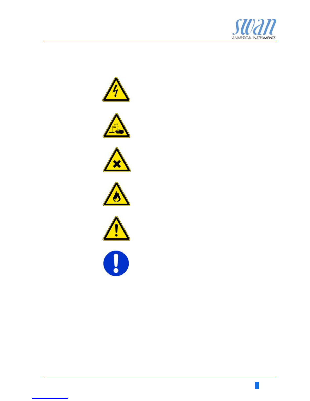
Warning Signs The importance of the warning signs in this manual.
1.2. General Safety Regulations
Legal
Requirements
The user is responsible for proper system operation.
All precautions must be followed to ensure safe operation of the instrument.
Spare Parts
and
Disposables
Use only official SWAN spare parts and disposables. If other parts
are used during the normal warranty period, the manufacturer’s
warranty is voided.
Electrical shock hazard
Corrosive
Harmful to health
Flammable
Warning general
Attention general
Page 8

6 A-96.250.461 / 070318
AMI Rescon
Safety Instructions
Modifications Modifications and instrument upgrades shall only be carried out by
an authorized Service Technician. SWAN will not accept responsibility for any claim resulting from unauthorized modification or alteration.
WARNING
Electrical Shock Hazard
If proper operation is no longer possible, the instrument must be
disconnected from all power lines, and measures must be taken
to prevent inadvertent operation.
To prevent from electrical shock, always make sure that the
ground wire is connected.
Service shall be performed by authorized personnel only.
Whenever electronic service is required, disconnect instru-
ment power and power of devices connected to.
–relay 1,
–relay 2,
– alarm relay
WARNING
For safe instrument installation and operation you must read
and understand the instructions in this manual.
WARNING
Only SWAN trained and authorized personnel shall perform the
tasks described in this document.
1.3. Restrictions for use
The AMI Rescon is designed for determination of specific conductivity or resistivity in high purity water.
To avoid clogging the flow cell, prevent sand, oil or solids, from entering into the flow cell.
Sufficient sample flow is coercive for the correct function of the instrument. To determine values near 18.18 MOhm-cm exactly, a
sample flow of 70–100 l/h is needed.
Page 9

AMI Rescon
Product Description
A-96.250.461 / 070318 7
2. Product Description
2.1. Description of the System
This instrument is applicable for the determination of specific resistivity or specific conductivity in high purity water.
Measuring
Principle
The resistivity of high purity water is determined with a sensor consisting of two metal electrodes. The characteristics of each sensor
is expressed as cell constant. An alternating voltage (to minimize
polarization effects) is applied to two electrodes. Depending on the
concentration of ions in the sample, a signal results between the
electrodes which is proportional to the resistivity of the water.
The measuring result is indicated as resistivity or conductivity. The
conductivity measurement depends on temperature, as the mobility
of ions increase with rising temperature. To eliminate these effects,
the temperature is determined simultaneous with an incorporated
NT5K temperature sensor. Several temperature compensation
curves for different applications are available.
Signal
Outputs
Two signal outputs programmable for measured values (freely scalable, linear, bilinear, log) or as continuous control output (control
parameters programmable).
Current loop: 0/4 –20 mA
Maximal burden: 510 Ω
Third signal output available as an option. The third signal output
can be operated as a current source or as a current sink (selectable
via switch).
Relays Two potential-free contacts programmable as limit switches for
measuring values, controllers or timer for system cleaning with automatic hold function.
Maximum load: 1 A/ 250 VAC
Alarm Relay One potential free contact.
Alternatively:
Open during normal operation, closed on error and loss of
power.
Closed during normal operation, open on error and loss of
power.
Summary alarm indication for programmable alarm values and instrument faults.
Page 10

8 A-96.250.461 / 070318
AMI Rescon
Product Description
Input One input for potential-free contact to freeze the measuring value
or to interrupt control in automated installations. Programmable as
HOLD or OFF function.
Communica-
tion interface
(optional)
USB Interface for logger download.
Third signal output (can be used in parallel to the USB interface)
RS485 with Fieldbus protocol Modbus or Profibus DP
HART interface
Safety
Features
No data loss after power failure. All data is saved in non-volatile
memory.
Over voltage protection of in- and outputs.
Galvanic separation of measuring inputs and signal outputs.
Standard
flow cell
A QV-Hflow flow cell is supplied with the Monitor as standard.
USP Operat-
ing Mode
The USP Operating Mode implemented in the firmware of the AMI
Rescon transmitter allows the measurement of pharmaceutical water according to the USP <645>.
If the USP Operating Mode is set to <off> conductivity or resistivity
standard measurement with automatic temperature compensation
is performed.
If the USP Operating Mode is set to <on>, the temperature compensation function is disabled. The uncompensated measuring values are compared with the values of an implemented table defined
by USP (see table below). If the deviation of the measured values
is too high, the Error 15 (USP Error) is issued.
Temperature [°C] Conductivity [S/cm] Temperature [°C] Conductivity [S/cm]
0 0.6 55 2.1
5 0.8 60 2.2
10 0.9 65 2.4
15 1.0 70 2.5
20 1.1 75 2.7
25 1.3 80 2.7
30 1.4 85 2.7
35 1.5 90 2.7
40 1.7 95 2.9
45 1.8 100 3.1
50 1.9
Page 11
AMI Rescon
Product Description
A-96.250.461 / 070318 9
Conductivity
QC-Kit Test
Plug
The implemented Transmitter Test together with Conductivity QCKit Test Plug containing a traceable high precision resistor allows to
perform a verification of he measuring electronics at any time.
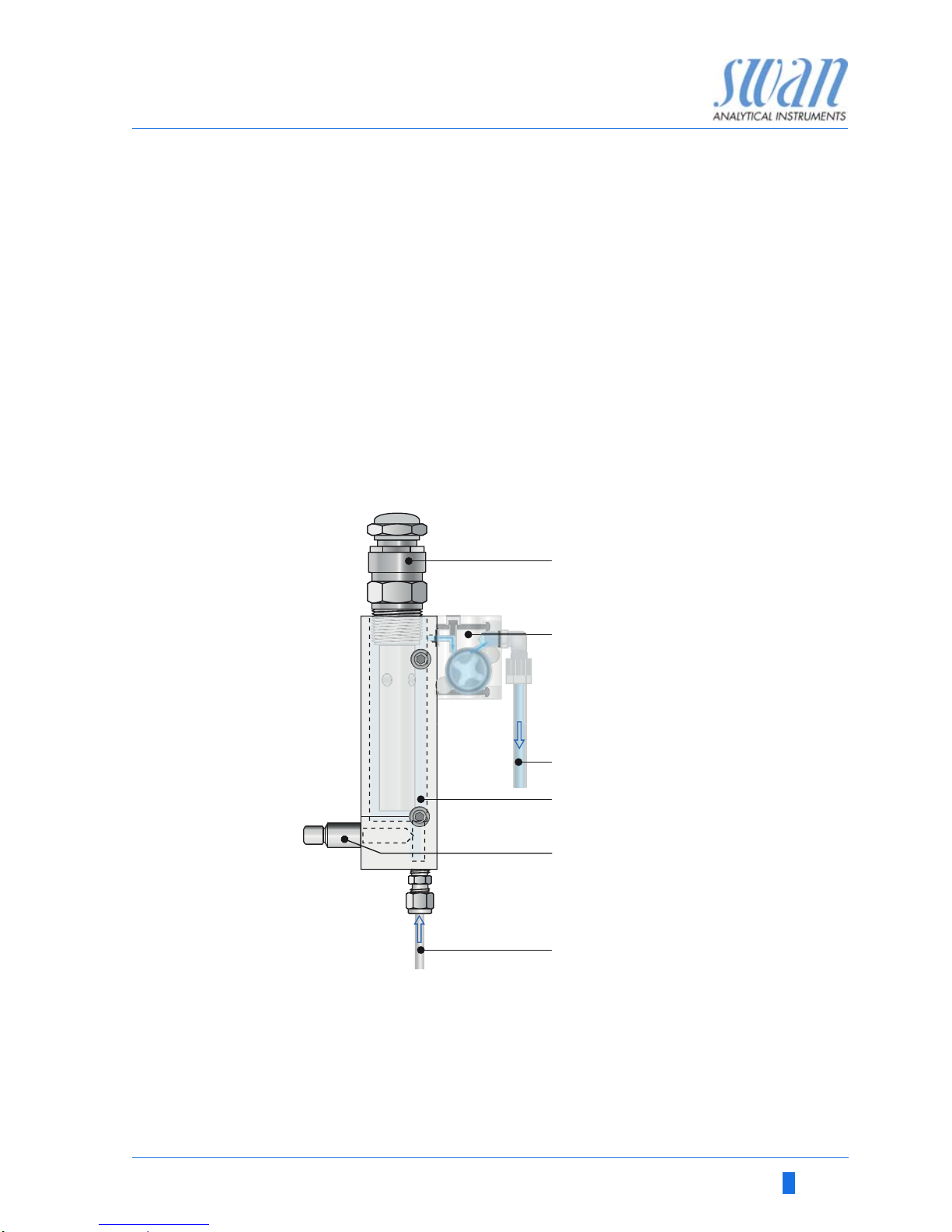
Fluidics The flow cell QV-Hflow consists of the flow cell block [D], the flow
sensor [B] and the flow regulating valve [E].
The conductivity sensor RC-U [A] with integrated temperature sen-
sor is screwed into the flow cell block [D].
The sample enters at the sample inlet [F]. It flows through the flow
regulating valve [E], where the flow rate can be adjusted. Then the
sample flows through the flow cell block [D] were the resistivity of
the sample is measured.
The sample leaves the flow cell block via flow meter through the
sample outlet [C].
A
B
C
Sensor RC-U
Flow sensor
Sample outlet
D
E
F
Flow cell block
Flow regulating valve
Sample inlet
A
B
C
D
E
F
Page 12

10 A-96.250.461 / 070318
AMI Rescon
Product Description
2.2. Instrument Specification
Power Supply Voltage:
Power consumption:
100–240 VAC (± 10%)
50/60 Hz (± 5%)
or 24 VDC (± 10%)
max. 30 VA
Electronics Aluminium with a protection degree of IP 66 / NEMA 4X
housing Ambient temperature:
Limit range of operation:
Storage and transport:
Humidity:
Display:
-10 to +50 °C
-25 to +65 °C
-30 to +85 °C
10–90% rel., non condensing
backlit LCD, 75 x 45 mm
Measuring
range
Resistivity:
Conductivity:
0.01–18.18 M-cm
0.055–1000 s/cm
Sample
requirements
Flow rate:
Temperature
Sample inlet pressure:
Sample outlet pressure:
70– 100 l/h
up to 95 °C
up to 2 bar
pressure free
On-site The analyzer site must permit connections to:
requirements Sample inlet:
Sample outlet:
Swagelok tube 1/4” adapter
FEP flexible tube 6 mm
Max. Altitude: 2000 m above sea level
Page 13
AMI Rescon
Product Description
A-96.250.461 / 070318 11
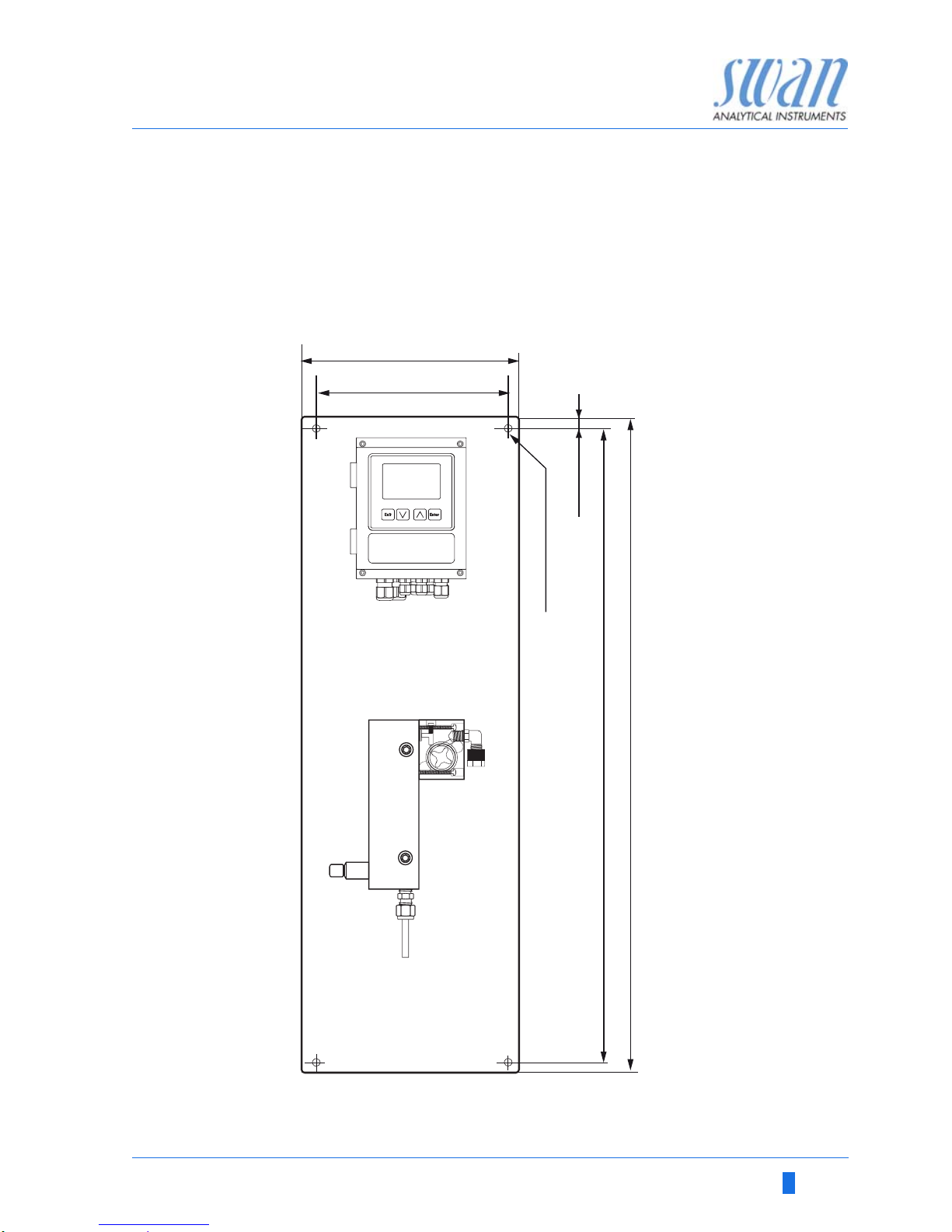
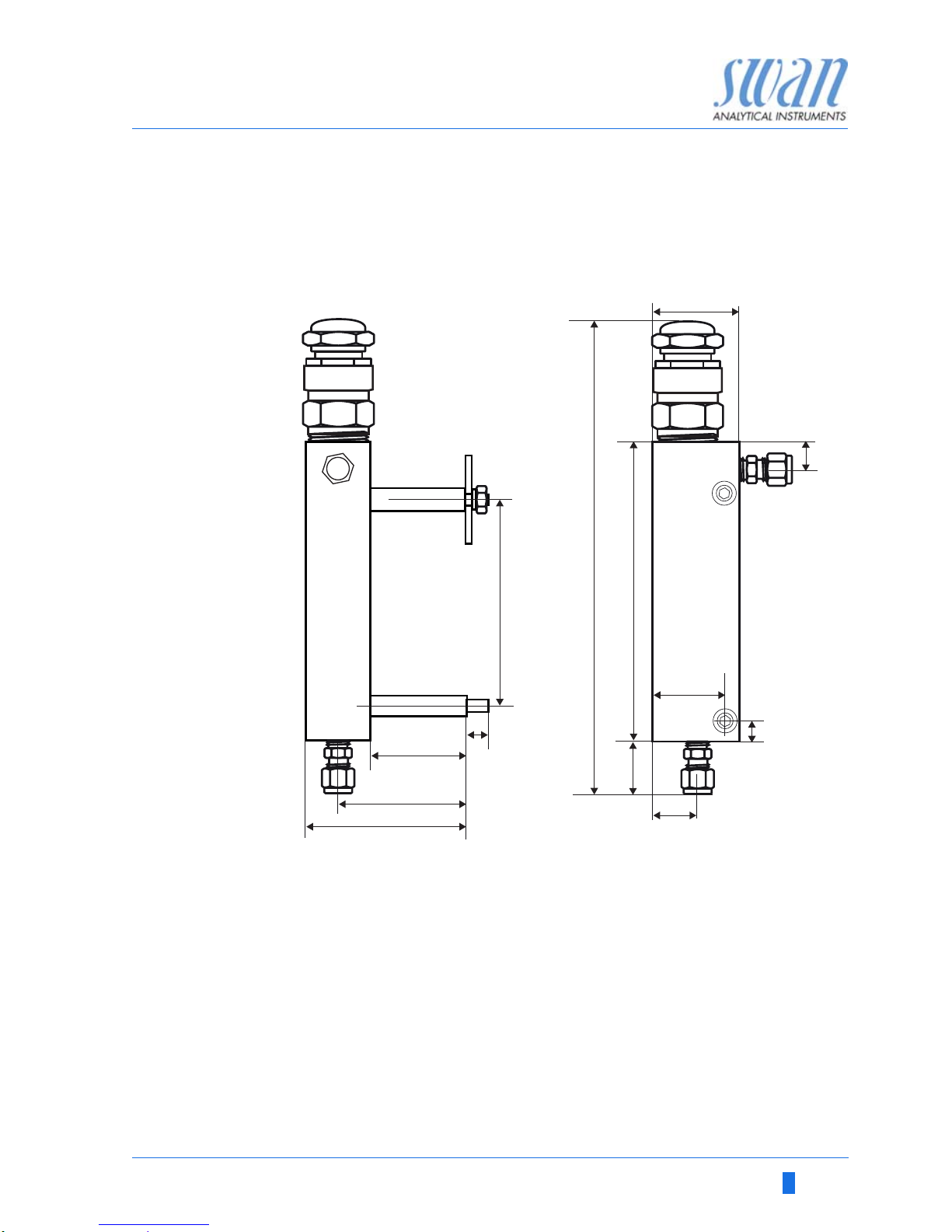
Dimensions Panel:
Mounting hole distance
Screws:
Weight:
280x850x180 mm, stainless steel
254x824
8 mm diameter
7.0 kg
AMI Rescon
850 mm / 33½”
13 mm / ½”
4 x dia.10 mm / ¼”
254 mm/ 10”
280 mm/ 11”
824 mm / 32
7
/
16
”
Page 14
12 A-96.250.461 / 070318
AMI Rescon
Product Description
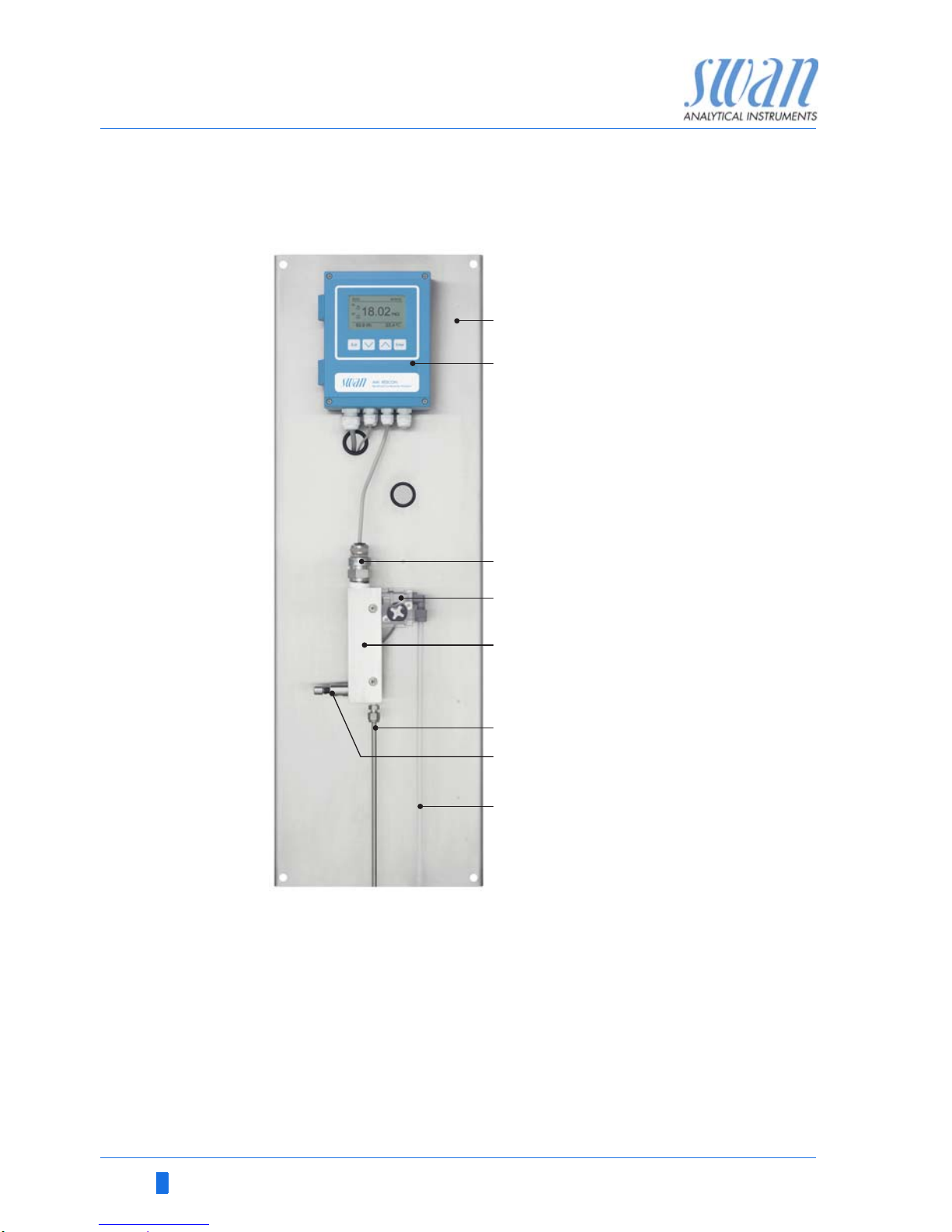
2.3. Instrument Overview
A
B
C
D
Panel
Transmitter
Sensor RC-U
Flow sensor
E
F
G
H
Flow cell
Sample inlet
Flow regulating valve
Sample outlet
A
B
C
D
E
F
H
G
Page 15
AMI Rescon
Product Description
A-96.250.461 / 070318 13
2.4. Single Components
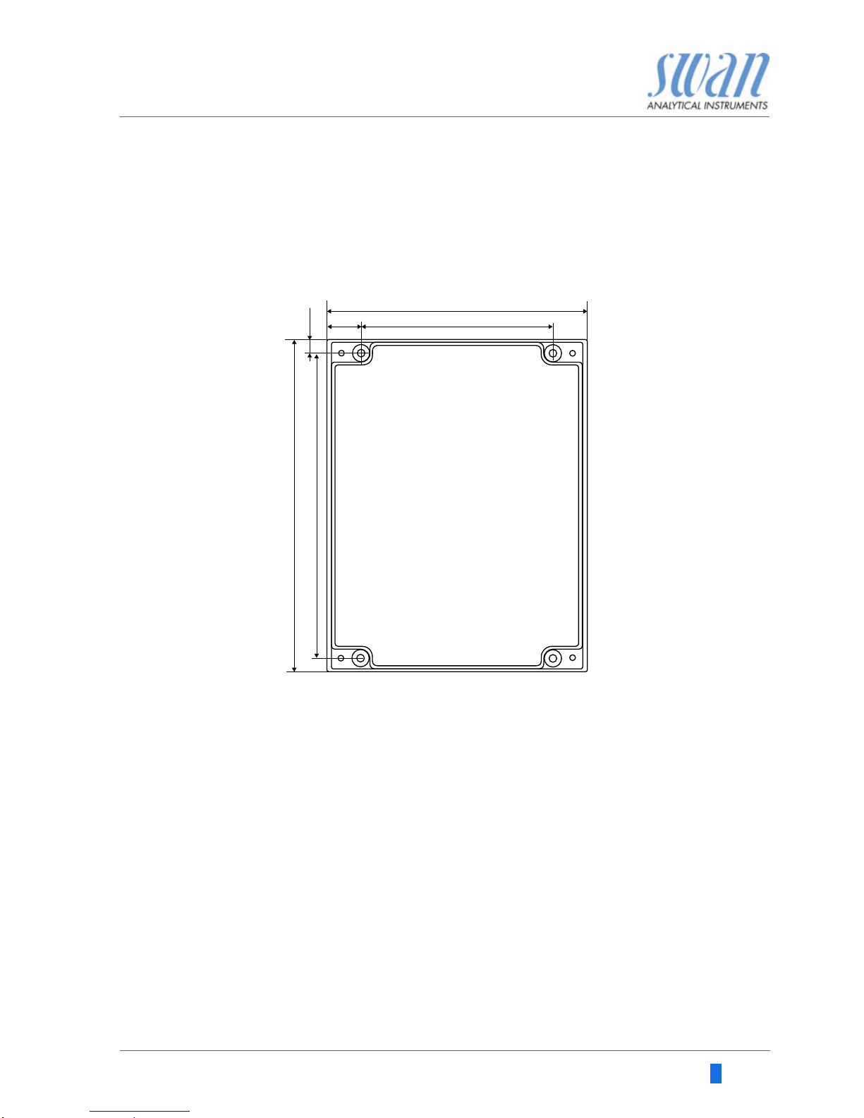
2.4.1 Transmitter AMI Rescon
Electronic transmitter and controller for conductivity measurement.
140
180
165
103
18.5
7.5
Dimensions Width:
Height:
Depth:
Weight:
140 mm
180 mm
70 mm
1.5 kg
Specifications Electronics case:
Protection degree:
Display:
Electrical connectors:
Cast aluminum
IP 66 / NEMA 4X
backlit LCD, 75 x 45 mm
screw clamps
Page 16
14 A-96.250.461 / 070318
AMI Rescon
Product Description
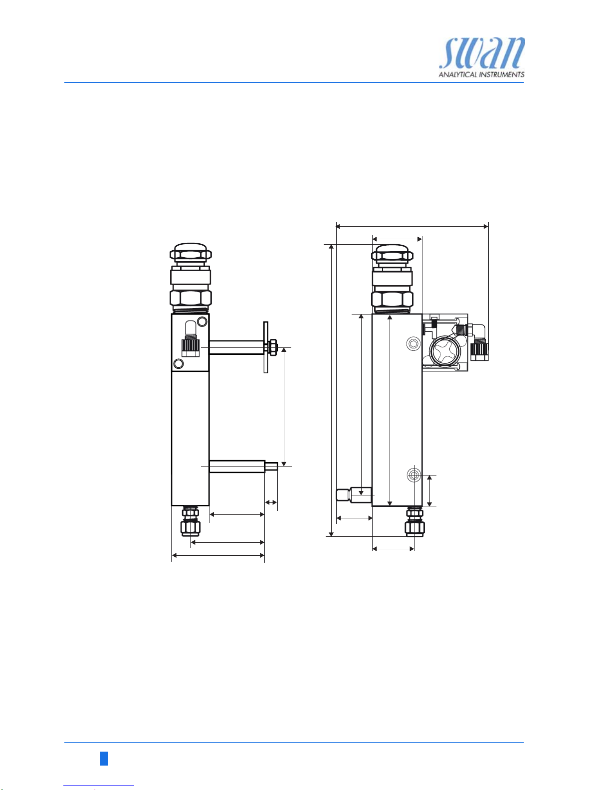
2.4.2 Flow Cell QV-Flow and QV-HFlow SS316L 130
Flow cell made of stainless steel with flow sensor for the connection
to SWAN transmitter and with manual flow regulating valve. Connection to tube with Swagelok adapter.
For one sensor with ¾" NPT thread
33
38
44
139
28
135 151234
96
10
45
60
75
Technical data Sample inlet:
Sample outlet:
Sample temperature:
Sample flow, QV-Flow:
Sample flow, QV-HFlow:
Sample inlet pressure:
Sample outlet pressure:
Swagelok G 1/4” thread
Serto elbow for 6 mm flexible tube
0–60 °C
3–25 l/h
10–120 l/ h
max. 15 bar at 50 °C
pressure free
Page 17
AMI Rescon
Product Description
A-96.250.461 / 070318 15
2.4.3 Flow Cell B-Flow SS316L 130
Flow cell made of stainless steel SS316L to connect to tubes.
For one sensor with ¾" NPT thread, fitting length 89 mm.
15
26
33
40
7
17
130
214
96
10
45
60
75
Technical data Sample inlet:
Sample outlet:
Sample temperature:
Sample inlet pressure:
Swagelok G 1/8” thread
Swagelok G 1/8” thread
-10–130 °C
max. 10 bar at 130 °C
Page 18
16 A-96.250.461 / 070318
AMI Rescon
Product Description
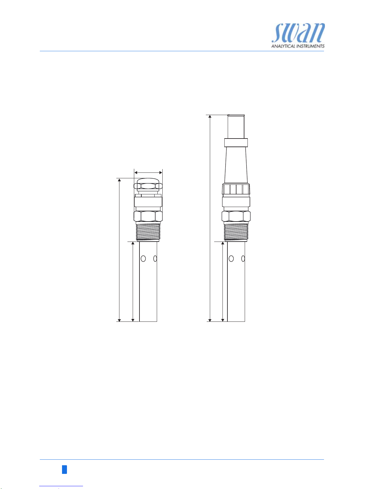
2.4.4 Swansensor RC U
Sensor for the measurement of the specific conductivity and specific resistivity in high purity water.
Swansensor RC U
with integrated cable
Swansensor RC U
with Plug
28
156
89
231
89
Specifications
RC U-Sensor
Measuring range:
respective:
Operating temperature:
Pressure:
Accuracy (at 25 °C):
Temperature sensor:
Thread:
0.055– 1000 S/cm
0.01–200 M
-10 to + 90 °C
max. 10 bar at + 90 °C
> +/- 0.5% up to 20 S/cm
+/- 1% from 20 s/ cm to 1000 S/cm
NT5K
3/4” NPT
Page 19

AMI Rescon
Installation
A-96.250.461 / 070318 17
3. Installation
3.1. Installation Checklist Monitors
Check Instrument’s specification must conform to the National Electri-
cal Code, all state and local codes, and all plant codes and standards for electrical equipment.
On site requirements
100–240 VAC ( 10%), 50/60 Hz ( 5%) or 24 VDC (±10%),
isolated power outlet with ground connection and 30 VA.
Sample line with sufficient sample flow and pressure (see Instru-
ment Specification, p. 10).
Installation Mounting of Instrument Panel, p. 18
Connecting Sample Inlet and Outlet, p. 19
Connect sensors
Only if single components have been ordered.
Connect the Resistivity Sensor Cable, p. 22.
Connect the Flow Sensor Cable, p. 22.
Electrical wiring
NOTICE: Do not switch on the Instrument until all electrical
connections are made.
Connect all external devices like limit switches, current loops
and pumps.
Power-up Establish Sample Flow, p. 33.
Switch on power.
Adjust sample flow according to flow cell specifications.
Instrument
set-up
Program all necessary parameters see Programming, p. 33
Program the flow cell type
Program the measuring mode (resistivity or conductivity).
Program all sensor data (cell constant, temperature correction,
cable length).
Program the required temperature compensation.
Program all parameters for external devices (interface,
recorders, etc.).
Program all parameters for instrument operation (limits,
alarms).
Run-in period If the conductivity value of the sample is very low, the sensor
might need some time until the correct reading is displayed
Page 20

18 A-96.250.461 / 070318
AMI Rescon
Installation
3.2. Mounting of Instrument Panel
The first part of this chapter describes the preparing and placing of
the system for use.
The instrument must only be installed by trained personnel.
Mount the instrument in vertical position.
For ease of operation mount it so that the display is at eye
level.
For the installation a kit containing the following installation
material is available:
– 4 Screws 8x 60 mm
– 4 Dowels
– 4 Washers 8.4/ 24 mm
Mounting re-
quirements
The instrument is only intended for indoor installation.
Instrument Specification, p. 10
Page 21
AMI Rescon
Installation
A-96.250.461 / 070318 19
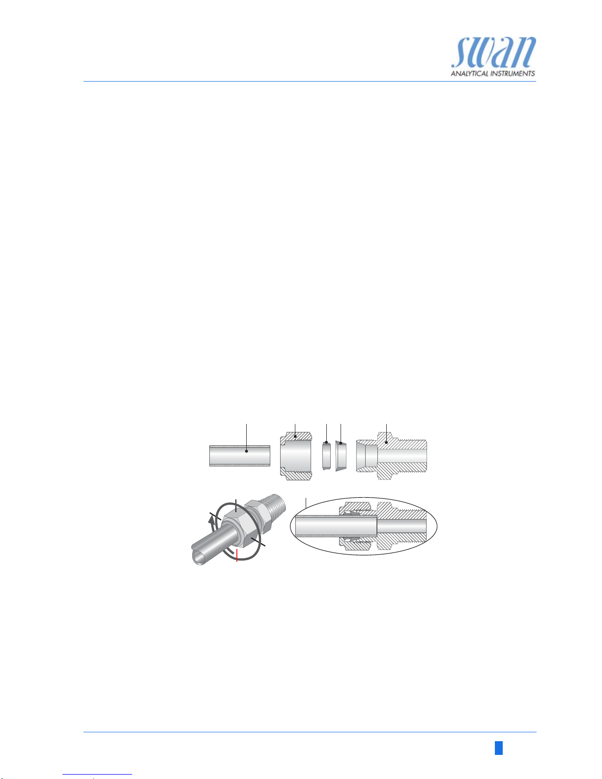
3.3. Connecting Sample Inlet and Outlet
3.3.1 Sample Inlet
Preparation For the sample inlet a stainless steel tube is connected to the Swa-
gelok fitting at the flow cell. Cut the tube to length and deburr it. The
tube must be straight and free from blemishes for approximately
1,5 x tube diameter from the end.
Lubrication with lubricating oil, MoS2, Teflon etc. is recommended
for the assembly and reassembly of bigger sized unions (thread,
compression cone).
Installation 1 Insert the compression ferrule [C] and the compression
cone [D] into the union nut [B].
2 Screw on the union nut onto the body, do not tighten it.
3 Push the stainless steel pipe through the union nut as far as it
reaches the stop of the body
4 Mark the union nut at 6 o’clock position.
5 While holding the fitting body steady, tighten the nut union 1¼
rotation using an open ended spanner.
3.3.2 Sample Outlet
FEP flexible tube 6 mm. Connect the tube to the serto elbow union
and Insert it into an atmospheric drain of sufficient capacity.
Max. tube length is 1.5 m. Do not connect longer tubes.
A
B
C
D
E
F
Tube
Union nut
Compression
ferrule
Compression
cone
Body
Tightened
connection
12
3
9
6
ABCDE
F
Page 22
20 A-96.250.461 / 070318
AMI Rescon
Installation
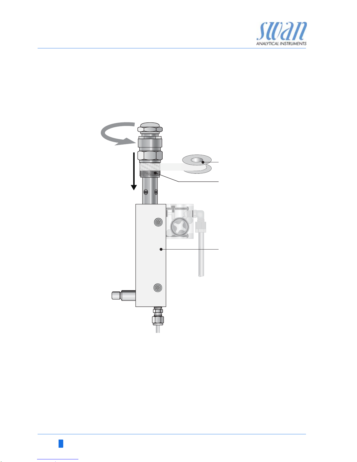
3.4. Install Sensor RCU
The following instruction applies for all, the flow cell and the pipe
flanges. To install the sensor RC U into a flow cell or a pipe flange
proceed as follows:
Install Sensor
into Flow Cell
Install Sensor
into a tube
Installation in a by-pass is recommended. Choose the installation
point carefully, to ensure the sensor is always filled with water, even
if sample flow is interrupted. To avoid the formation of air bubbles
inside the sensor make sure that the air vent holes are always submerged.
A
B
C
Teflon tape
Sensor thread
Flow cell
A
B
C
Page 23
AMI Rescon
Installation
A-96.250.461 / 070318 21
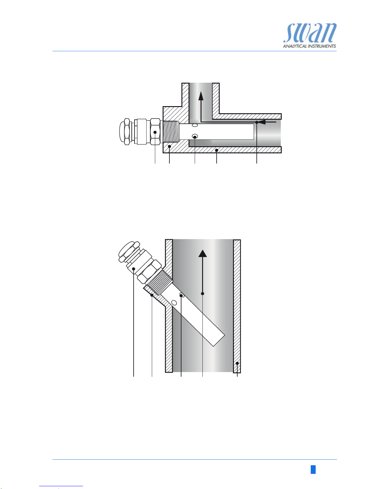
Installation
examples for
tube installa-
tion
1 Wrap 7 turns of teflon tape around the sensor thread.
2 Screw the sensor into the flow cell or the pipe flange.
3 Tighten the sensor well with a monkey spanner.
A
B
C
D
E
Sensor
Flange
Air vent hole
Tube
Flow direction
A
B
C
D
E
Sensor
Flange
Air vent hole
Flow direction
Tube
AB C D E
AB C ED
Page 24
22 A-96.250.461 / 070318
AMI Rescon
Installation
3.5. Connect the Resistivity Sensor Cable
WARNING
Electrical shock hazard!
Before opening the AMI Transmitter switch power off.
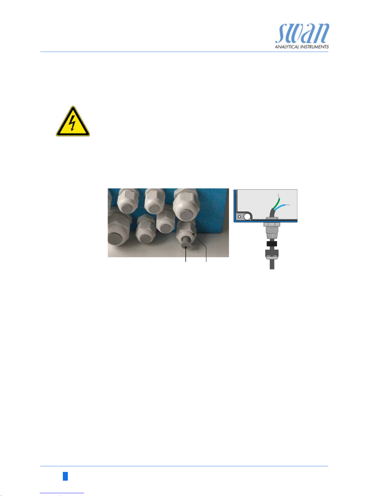
Use one of the cable glands to feed the sensor cable into the sensor housing.
1 Choose a suitable cable gland, see chapter Electrical Connec-
tions, p. 23.
2 Remove the plug [A] from the cable gland [B].
3 Open the AMI transmitter housing.
4 Feed the sensor cable through the cable gland [B] into the
transmitter housing.
5 Connect the cable to the terminals according to the connecting
diagram see Connection Diagram, p. 25.
6 Close the AMI transmitter housing.
7 Switch on power.
3.6. Connect the Flow Sensor Cable
If a flow cell with a flow sensor was ordered (QV-Flow) connect it to
the AMI Transmitter. Proceed according to chapter Connect the Re-
sistivity Sensor Cable, p. 22.
BA
Page 25
AMI Rescon
Installation
A-96.250.461 / 070318 23
3.7. Electrical Connections
WARNING
Risk of electrical shock.
Do not perform any work on electrical components if the transmitter is switched on. Failure to follow safety instructions could
result in serious injury or death.
Always turn off AC power before manipulating electric parts.
Grounding requirements: Only operate the instrument from
an power outlet which has a ground connection.
Make sure the power specification of the instrument corre-
sponds to the power on site.
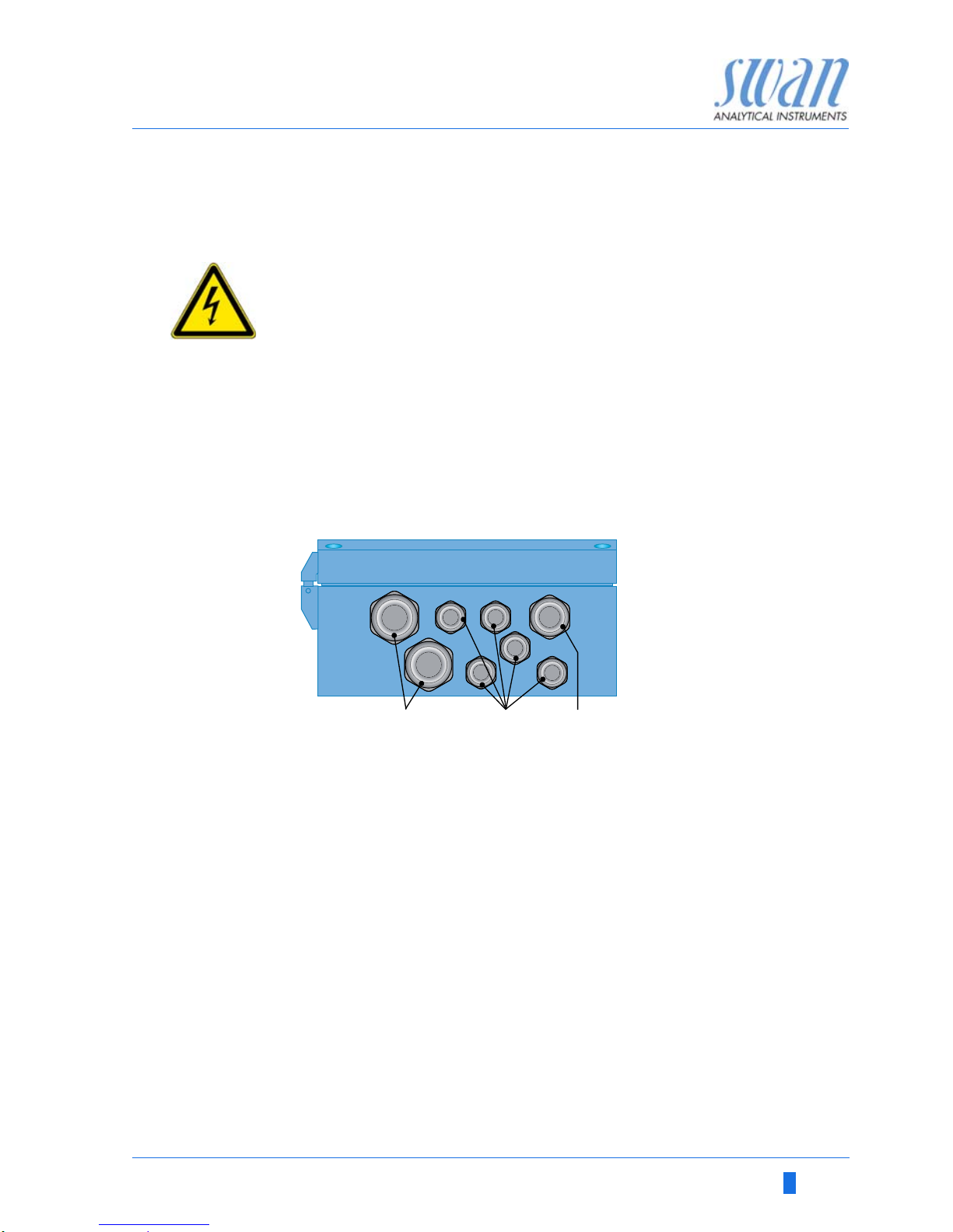
Cable
thicknesses
In order to comply with IP66, use the following cable thicknesses
NOTICE: Protect unused cable glands
Wire For Power and Relays: Use max. 1.5 mm
2
/ AWG 14
stranded wire with end sleeves.
For Signal Outputs and Input: Use 0.25 mm
2
/ AWG 23
stranded wire with end sleeves.
A
B
C
PG 11 cable gland: cable Ø
outer
5–10 mm
PG 7 cable gland: cable Ø
outer
3–6.5 mm
PG 9 cable gland: cable Ø
outer
4–8 mm
ABC
Page 26

24 A-96.250.461 / 070318
AMI Rescon
Installation
WARNING
External Voltage.
External supplied devices connected to relay 1 or 2 or to the
alarm relay can cause electrical shocks
Make sure that the devices connected to the following con-
tacts are disconnected from the power before resuming installation.
–relay 1
–relay 2
– alarm relay
WARNING
To prevent from electrical shock, do not connect the instrument
to the power unless the ground wire (PE) is connected.
Do not connect unless specifically instructed to do so.
WARNING
The mains of the AMI Transmitter must be secured by a main
switch and appropriate fuse or circuit breaker.
Page 27

AMI Rescon
Installation
A-96.250.461 / 070318 25
3.7.1 Connection Diagram
CAUTION
Use only the terminals shown in this diagram, and only for the
mentioned purpose. Use of any other terminals will cause short
circuits with possible corresponding consequences to material
and personnel.
Page 28

26 A-96.250.461 / 070318
AMI Rescon
Installation
3.7.2 Power Supply
WARNING
Risk of electrical shock
Do not perform any work on electrical components if the transmitter is switched on. Failure to follow safety instructions could
result in serious injury or death.
Always turn off AC power before manipulating electric parts.
Installation and maintenance of electrical parts must be per-
formed by professionals.
NOTICE: The protective earth wire (Ground) has to be
connected to the grounding terminal.
Installation
requirements
The installation must meet the following requirements.
Mains fuse 1.6 AT
Mains cable to comply with standards IEC 60227 or IEC
60245; flammable rating FV1
Mains equipped with an external switch or circuit-breaker
– near the instrument
– easily accessible to the operator
– marked as interrupter for AMI Rescon
A
B
C
D
Power supply connector
Neutral conductor, Terminal 2
Phase conductor, Terminal 1
Protective earth PE
A
B
C
D
Page 29

AMI Rescon
Installation
A-96.250.461 / 070318 27
3.8. Relay Contacts
Programming of the relay contacts see 5.3 Relay Contacts, p. 65
3.8.1 Input
NOTICE: Use only potential-free (dry) contacts.
The total resistance (sum of cable resistance and resistance of
the relay contact) must be less than 50 Ω.
• Terminals 16/42
If signal output is set to hold, measurement is interrupted if input is
active.
For programming see menu 5.3.4, p. 71
3.8.2 Alarm Relay
NOTICE: Max. load 1 AT / 250 VAC
Alarm output for system errors.
Error codes see Error List, p. 48
Programming see menu 5.3.1, p. 65
NOTICE: With certain alarms and certain settings of the AMI
transmitter the alarm relay does not switch. The error, however,
is shown on the display.
1) usual use
Terminals Description Relay connection
NC
1)
Normally
Closed
10/11 Active (opened) during normal
operation.
Inactive (closed) on error and
loss of power.
NO
Normally
Open
12/11 Active (closed) during normal
operation.
Inactive (opened) on error and
loss of power.
10
12
11
0V
1)
10
12
11
0V
Page 30

28 A-96.250.461 / 070318
AMI Rescon
Installation
3.8.3 Relay Contacts 1 and 2
NOTICE: Rated load 1 AT / 250 VAC
Relay 1 and 2 can be configured as normally open or as normally
closed. Standard for both relays is normally open. To configure a
Relay as normally closed, set the jumper in the upper position.
NOTICE: Some error codes and the instrument status may
influence the status of the relays described below.
For programming see Menu Installation 5.3.2 and 5.3.3, p. 67
Relay
config. Terminals
Jumper
pos. Description Relay configuration
Normally
Open
6/7: Relay 1
8/9: Relay 2
Inactive (opened) during
normal operation and
loss of power.
Active (closed) when a
programmed function is
executed.
Normally
Closed
6/7: Relay 1
8/9: Relay 2
Inactive (closed) during
normal operation and
loss of power.
Active (opened) when a
programmed function is
executed.
6
0V
7
6
0V
7
A
B
Jumper set as normally open (standard setting)
Jumper set as normally closed
A
B
Page 31

AMI Rescon
Installation
A-96.250.461 / 070318 29
CAUTION
Risk of damage of the relays in the AMI Transmitter due to
heavy inductive load.
Heavy inductive or directly controlled loads (solenoid valves,
dosing pumps) may destroy the relay contacts.
To switch inductive loads > 0.1 A use an AMI relay box avail-
able as an option or suitable external power relays.
Inductive load Small inductive loads (max 0.1A) as for example the coil of a power
relay can be switched directly. To avoid noise voltage in the
AMI Transmitter it is mandatory to connect a snubber circuit in parallel to the load. A snubber is not necessary if an AMI relaybox is
used.
Resistive load Resistive loads (max. 1A) and control signals for PLC, impulse
pumps and so on can be connected without further measures
Actuators Actuators, like motor valves, are using both relays: One relay con-
tact is used for opening, the other for closing the valve, i.e. with the
2 relay contacts available, only one motor valve can be controlled.
Motors with loads bigger than 0.1 A must be controlled via external
power relays or an AMI relay box.
A
B
C
D
E
AC or DC power supply
AMI Transmitter
External power relay
Snubber
Power relay coil
A
BC
DE
A
B
C
AMI Transmitter
PLC or controlled pulse pump
Logic
AB
C
A
B
C
AC or DC power supply
AMI Transmitter
Actuator
M
A
BC
Page 32

30 A-96.250.461 / 070318
AMI Rescon
Installation
3.9. Signal Outputs
3.9.1 Signal Output 1 and 2 (current outputs)
NOTICE: Max. burden 510 Ω
If signals are sent to two different receivers, use signal isolator
(loop isolator).
Signal output 1: Terminals 14 (+) and 13 (-)
Signal output 2: Terminals 15 (+) and 13 (-)
For programming see Chapter 9, 5.2 Signal Outputs, p. 61, Menu
Installation
3.10. Interface Options
The slot for interfaces can be used to expand the functionality of
the AMI instrument with either:
Third signal output
a Profibus or Modbus connection
a HART connection
an USB Interface
A
B
C
D
AMI Transmitter
Slot for interfaces
Frontend PCB
Screw terminals
A
B
C
D
Page 33

AMI Rescon
Installation
A-96.250.461 / 070318 31
3.10.1 Signal Output 3
Terminals 38 (+) and 37 (-).
Requires the additional board for the third signal output 0/4–20 mA.
The third signal output can be operated as a current source or as a
current sink (switchable via switch [A]). For detailed information see
the corresponding installation instruction.
NOTICE: Max. burden 510 Ω.
Third signal output 0/4 - 20 mA PCB
3.10.2 Profibus, Modbus Interface
Terminal 37 PB, Terminal 38 PA
To connect several instruments by means of a network or to config-
ure a PROFIBUS DP connection, consult the PROFIBUS manual.
Use appropriate network cable.
NOTICE: The switch must be ON, if only one instrument is
installed, or on the last instrument in the bus.
Profibus, Modbus Interface PCB (RS 485)
A Operating mode selector switch
A
A On - OFF switch
ON
OFF
A
Page 34

32 A-96.250.461 / 070318
AMI Rescon
Installation
3.10.3 HART Interface
Terminals 38 (+) and 37 (-).
The HART interface PCB allows for communication via the HART
protocol. For detailed information, consult the HART manual.
HART Interface PCB
3.10.4 USB Interface
The USB Interface is used to store Logger data and for Firmware
upload. For detailed information see the corresponding installation
instruction.
The optional third signal output 0/4 – 20 mA PCB [B] can be
plugged onto the USB interface and used in parallel.
USB Interface
A USB interface PCB
B Third signal output 0/4 - 20 mA PCB
A
B
Page 35

AMI Rescon
Instrument Setup
A-96.250.461 / 070318 33
4. Instrument Setup
4.1. Establish Sample Flow
1 Open the flow regulating valve.
2 Wait until the flow cell is completely filled.
3 Switch on power.
NOTICE: To allow a precise measurement in the range
between 18–18.18 MΩ, set the sample flow to 70–100 l/h.
4.2. Programming
Set all necessary parameters in menu 5 <Installation>, further information about sensor parameters see 5.1 Sensors, p. 60.
Flow measurement
Measuring Mode
USP Operating Mode
Sensor parameters
Temperature compensation
Program all parameters for external devices (interface, re-
corders, etc.). Program all parameters for instrument operation (limits, alarms). See Program Overview, p. 51, for
explanations, see Program List and Explanations, p. 56.
Flow
Measurement
Menu 5.1.1
Select the flow cell you are using:
None
Q-Flow
Q-HFlow
Q-Flow can be used for flow rates up to 25 l/h.
Q-HFlow can be used for flow rates up to 120 l/ h.
Meas. Mode Menu 5.1.2
Select Resistivity or Conductivity according to your application.
Page 36

34 A-96.250.461 / 070318
AMI Rescon
Instrument Setup
USP Operating
Mode
Menu 5.1.3
The USP Operating Mode implemented in the firmware of the AMI
Rescon transmitter allows the measurement of pharmaceutical water according to the USP <645>.
If the USP Operating Mode is set to <off> conductivity or resistivity
standard measurement is performed.
If the USP Operating Mode is set to <on>, the uncompensated
measuring values are compared with the values of an implemented
table defined by USP. If the deviation is too high, the Error 15 (USP
Error) is issued.
Further information see USP Operating Mode, p. 8
Sensor
Parameters
Menu 5.1.4:
Enter the following parameters printed on the sensor label.
Cell constant ZK
Temperature correction DT
Sensor cable length.If the sensor cable length is 0.3 m, set the
cable length to 0 m.
Tem p.
Compensation
Menu 5.1.5
Choose between:
none
coefficient
neutral salts
high purity water
strong acids
strong bases
ammonia, ethanolamine
morpholine
87.322.210
SW2540001 ZK = 0.00997
DT = -0.13 °C
RC U, 0.3 m
Page 37

AMI Rescon
Operation
A-96.250.461 / 070318 35
5. Operation
5.1. Keys
Program
Access, Exit
A to exit a menu or command (rejecting any changes)
to move back to the previous menu level
B to move DOWN in a menu list and to decrease digits
C to move UP in a menu list and to increase digits
D to open a selected sub-menu
to accept an entry
Exit Enter
BCDA
25.4°C
RUN
9 l/h
14:10:45
R1
17.04 M
R2
1
Installation
Operation
Diagnostics
Messages
Maintenance
Main Menu
Enter
Exit
Page 38

36 A-96.250.461 / 070318
AMI Rescon
Operation
5.2. Display
Relay status, symbols
A
RUN normal operation
HOLD input closed or cal delay: Instrument on hold (shows
status of signal outputs).
OFF input closed: control/limit is interrupted (shows status
of signal outputs).
B
ERROR Error
Fatal Error
C
Keys locked, transmitter control via Profibus
D
Time
E
Process values
F
Sample temperature
G
Sample flow
H
Relay status
upper/lower limit not yet reached
upper/lower limit reached
control upw./downw. no action
control upw./downw. active, dark bar indicates control intensity
motor valve closed
motor valve: open, dark bar indicates approx. position
timer
timer: timing active (hand rotating)
RUN
15:20:18
R1
R2
43.5 l/h 24.8°C
MΩ
17.98
AB D
E
F
H
G
C
Page 39

AMI Rescon
Operation
A-96.250.461 / 070318 37
5.3. Software Structure
Menu Messages 1
Reveals pending errors as well as an event history
(time and state of events that have occurred at an
earlier point of time).
It contains user relevant data.
Menu Diagnostics 2
Provides user relevant instrument and sample data.
Menu Maintenance 3
For instrument calibration, relay and signal output
simulation, and to set the instrument time.
It is used by the service personnel.
Menu Operation 4
User relevant parameters that might need to be
modified during daily routine. Normally password
protected and used by the process-operator.
Subset of menu 5 - Installation, but process-related.
Menu Installation 5
For initial instrument set up by SWAN authorized
person, to set all instrument parameters. Can be
protected by means of password.
1
Messages
Operation
Maintenance
Diagnostics
Main Menu
Installation
1.1
Pending Errors
Messages
Message List
2.1
Interface
I/O State
Sample
Identification
Sensors
Diagnostics
3.1
Simulation
Transmitter checkoff
Maintenance
Set Time 23.09.06 16:30:00
Fine adjust
4.1
Logger
Relay Contacts
Sensors
Operation
5.1
Interface
Miscellaneous
Relay Contacts
Sensors
Signal Outputs
Installation
Page 40

38 A-96.250.461 / 070318
AMI Rescon
Operation
5.4. Changing Parameters and values
Changing
parameters
The following example shows how to set the Q-Hflow sensor:
Changing
values
1 Select the parameter you want to
change.
2 Press [Enter]
3 Press [ ] or [ ] key to
highlight the required parameter.
4 Press [Enter] to confirm the selec-
tion or [Exit] to keep the previous
parameter).
The selected parameter is
indicated (but not saved yet).
5 Press [Exit].
Yes is highlighted.
6 Press [Enter] to save the new pa-
rameter.
The system reboots, the new
parameter is set.
5.1.1
Sensors
Temp. Compensation
Flow None
Meas. Mode Resistivity
Sensor parameters
USP Operating Mode off
5.1.1
Sensors
Temp. Compensation
Flow None
Meas. Mode Resistivity
Sensor parameters
USP Operating Mode off
Flow
None
Q-Hflow
Q-flow
5.1.1
Sensors
Temp. Compensation
Flow Q-Hflow
Meas. Mode Resistivity
Sensor parameters
USP Operating Mode off
5.1.1
Sensors
Temp. Compensation
Meas. Mode Resistivity
Sensor parameters
USP Operating Mode off
Flow Q-Hflow
No
Save ?
Yes
1 Select the value you want to
change.
2 Press [Enter].
3 Set required value with [ ] or
[] key.
4 Press [Enter] to confirm the new
value.
5 Press [Exit].
Yes is highlighted.
6 Press [Enter] to save the new val-
ue.
5.3.1.1.1
Alarm High 200M
Alarm
Alarm Low 0 M
Hysteresis 1 M
Delay 5 Sec
5.3.1.1.1
Alarm
Alarm Low 0 M
Hysteresis 1 M
Delay 5 Sec
Alarm High 179 M
Page 41

AMI Rescon
Maintenance
A-96.250.461 / 070318 39
6. Maintenance
6.1. Maintenance Table
6.2. Stop of Operation for Maintenance
WARNING
Electrical shock hazard!
Do not carry out maintenance work during normal operation.
Always turn off power before manipulating electric parts.
1 Shut off power of the instrument.
2 Stop sample flow by closing the flow regulating valve [C].
If necessary Clean sensor
According to
USP regulations
Perform a transmitter check
Page 42

40 A-96.250.461 / 070318
AMI Rescon
Maintenance
6.3. Maintenance of Sensor
6.3.1 Clean Sensor
The Swansensor RC-U is largely maintenance free. However, depending on the application, it can be contaminated, which may
cause problems.
The Swansensor RC-U is available in the following 2 different versions:
Sensor with fix installed cable
Sensor with plug
NOTICE: Sensor with fix installed cable
• To avoid damage of the sensor cable due to torsion when
screwing the sensor out of the flow cell, disconnect the cable
from the terminals in the AMI transmitter.
To remove the sensor with fix installed cable from the flow cell proceed as follows:
Remove the
sensor with fix
cable
1 Open the transmitter housing.
2 Disconnect the sensor cable from the terminals.
3 Remove the sensor cable from the transmitter housing.
4 Unscrew and remove the sensor [A] from the flow cell block [B],
use a monkey spanner.
5 Remove the teflon tape from the sensor thread.
6 Clean the sensor with soap water.
7 Rinse the sensor well with high purity water.
Page 43

AMI Rescon
Maintenance
A-96.250.461 / 070318 41
Install the
sensor with fix
cable
1 Wrap 7 turns of teflon tape around the sensor thread.
2 Screw the sensor into the flow cell and tighten it well.
3 Feed the sensor cable into the transmitter housing.
4 Connect the sensor cable to the terminals of the AMI transmit-
ter, see Electrical Connections, S. 23.
5 Close the transmitter housing.
6 Open the flow regulating valve [C].
7 Switch on power.
To remove the sensor with plug from the flow cell proceed as follows:
A
B
C
Sensor
Flow cell
Flow regulating valve
A
B
C
Page 44

42 A-96.250.461 / 070318
AMI Rescon
Maintenance
Remove the
sensor with
plug
1 Unscrew and remove the sensor plug [A] from the sensor [B].
2 Proceed according to “Remove the Sensor with fix cable”,
step 4.
Install the sen-
sor with plug
1 Wrap 7 turns of teflon tape around the sensor thread.
2 Screw the sensor into the flow cell and tighten it well.
3 Screw the sensor plug on to the senor
4 Open the flow regulating valve [C].
5 Switch on power.
A
B
Sensor plug
Sensor
A
B
Page 45

AMI Rescon
Maintenance
A-96.250.461 / 070318 43
6.4. Conductivity-Resistivity QC-Kit Test Plug
The QC-Kit test plug fulfills the requirements of the United States
Pharmacopeia (USP).
6.4.1 Introduction
The test plug consists of 2 high precision resistors for conductivity
and temperature.
The plug has a resistor of
5000 (+/- 1%) for temperature
181800 (+/- 1%) for conductivity.
NOTICE: Keep test kit absolutely dry!
Several variables enter into the calculation of specific conductivity.
Values like the cell constant, temperature compensation algorithm,
cable length and temperature correction of the sensor are stored in
the memory of the conductivity instrument.
Test mode For a quick and easy test, the AMI Rescon transmitter has the test
mode <Transmitter check> that enables testing without changing
any of these values. When leaving the test mode, all parameters
will be set back to their original value.
Page 46

44 A-96.250.461 / 070318
AMI Rescon
Maintenance
6.4.2 Carry out a transmitter check
Connect the
test resistor
1 Unscrew and remove the sensor plug [A] from the sensor [C]
2 Screw the sensor plug onto the test resistor [B].
A
B
C
Sensor plug
Test resistor
Sensor RC U
A
B
C
Page 47

AMI Rescon
Maintenance
A-96.250.461 / 070318 45
Start transmit-
ter check
NOTICE: If Transmitter Check is switched on, the main menus
<Operation> and <Installation> are not accessible.
6.5. Fine Adjust
The function fine adjust is only available if the AMI Rescon is set to
the measuring mode resistivity.
The function “Fine Adjust” is performed automatically every night at
00:30 h.
It is also possible to start the function “Fine Adjust” manually in the
menu <Maintenance/Fine adjust>.
1 Navigate to menu <Maintenance> /
<Transmitter check>.
2 Press [Enter].
3 Select <on> and confirm with [En-
ter]
The Transmitter check is now
active
4 Abandon the menu by pressing the
exit key twice.
5 Compare the displayed resistivity
or conductivity value and the temperature value with the value printed on the test resistor.
3.3
Set Time07.05.12 11:06:17
Maintenance
Fine adjust
Transmitter checkoff
Simulation
3.3
Set Time07.05.12 11:06:17
Maintenance
Fine adjust
Transmitter Checkoff
Simulation
off
Transmitter check
on
3.3
Set Time07.05.12 11:06:17
Maintenance
Fine adjust
Transmitter checkon
Simulation
Page 48

46 A-96.250.461 / 070318
AMI Rescon
Maintenance
6.6. Replacing Fuses
WARNING
External Voltage.
External supplied devices connected to relay 1 or 2 or to the
alarm relay can cause electrical shocks.
Make sure that the devices connected to the following con-
tacts are disconnected from the power before resuming installation.
–relay 1
–relay 2
– alarm relay
When a fuse has blown, find out the cause and fix it before replacing it with a new one.
Use tweezers or needle-nosed pliers to remove the defective fuse.
Use original fuses provided by SWAN only.
A
B
C
D
E
F
G
1.6 AT/250V Instrument power supply
1.0 AT/250V Relay 1
1.0 AT/250V Relay 2
1.0 AT/250V Alarm relay
1.0 AF/125V Signal output 2
1.0 AF/125V Signal output 1
1.0 AF/125V Signal output 3
A
B
CDEF G
Page 49

AMI Rescon
Maintenance
A-96.250.461 / 070318 47
6.7. Longer Stop of Operation
1 Stop sample flow.
2 Shut off power of the instrument.
3 Unscrew and remove the sensor.
4 Empty and dry the flow cell
Page 50

48 A-96.250.461 / 070318
AMI Rescon
Error List
7. Error List
Error
Non-fatal Error. Indicates an alarm if a programmed value is exceeded.
Such Errors are marked E0xx (bold and black).
Fatal Error (blinking symbol)
Control of dosing devices is interrupted.
The indicated measured values are possibly incorrect.
Fatal Errors are divided in the following two categories:
Errors which disappear if correct measuring conditions are re-
covered (i.e. Sample Flow low).
Such Errors are marked E0xx (bold and orange)
Errors which indicate a hardware failure of the instrument.
Such Errors are marked E0xx (bold and red)
Error or fatal Error
Error not yet acknowledged.
Check Pending Errors 1.1.5 * and
take corrective action.
Press [ENTER].
Navigate to menu Pending Errors.
Press [ENTER].
Press [ENTER] to acknowledge the
Pending Errors. The Error is reset and
saved in the Message List.
23 B/s
HOLD
PO4
14:10:45
R1
0.5 SR2
1
Installation
Operation
Diagnostics
Messages
Maintenance
Main Menu
1.1
Maintenance List
Pending Errors
Messages
Message List
1.1.5
Pending Errors
Error Code E002
Alarm low
<Enter> to Acknowledge
Page 51

AMI Rescon
Error List
A-96.250.461 / 070318 49
Error Description Corrective action
E001 Alarm high
– check process
– check programmed value
E002 Alarm low
– check process
– check programmed value
E007 Sample Temp. high
– check process
– check programmed value
E008 Sample Temp. low
– check process
– check programmed value
E009 Sample Flow high
– check sample flow
– check programmed value
E010 Sample Flow low
– establish sample flow
– clean instrument
– check programmed value
E011 Temp. shorted
– Check wiring of sensor
– Check sensor
E012 Temp. disconnected
– Check wiring of sensor
– Check sensor
E013 Case Temp. high
– check case/environment temperature
– check programmed value
E014 Case Temp. low
– check case/environment temperature
– check programmed value
E015 USP Error
– check process
E017 Control Timeout
– check control device or programming in
Installation, Relay contact, Relay 1/2
see 5.3.2 and 5.3.3, S. 67
E019 Sensor shorted
– Check wiring of sensor
– Check sensor
E020 Sensor interrupted
– Check wiring of sensor
– Check sensor
E024 Input active
– See If Fault Yes is programmed in
Menu see 5.3.4, S. 71
Page 52

50 A-96.250.461 / 070318
AMI Rescon
Error List
E026 IC LM75
– call service
E028 Signal output open
– check wiring on signal outputs 1 and 2
E030 EEProm Frontend
– call service
E031 Calibration Recout
– call service
E032 Wrong Frontend
– call service
E033 Power-on
– none, normal status
E034 Power-down
– none, normal status
E065 Transmitter check
–
Error Description Corrective action
Page 53

AMI Rescon
Program Overview
A-96.250.461 / 070318 51
8. Program Overview
For explanations about each parameter of the menus see Program
List and Explanations, S. 56.
Menu 1 Messages informs about pending errors and mainte-
nance tasks and shows the error history. Password protection
possible. No settings can be modified.
Menu 2 Diagnostics is always accessible for everybody. No
password protection. No settings can be modified.
Menu 3 Maintenance is for service: Calibration, simulation of
outputs and set time/date. Please protect with password.
Menu 4 Operation is for the user, allowing to set limits, alarm
values, etc. The presetting is done in the menu Installation
(only for the System engineer). Please protect with password.
Menu 5 Installation: Defining assignment of all inputs and
outputs, measuring parameters, interface, passwords, etc.
Menu for the system engineer. Password strongly recommended.
8.1. Messages (Main Menu 1)
Pending Errors Pending Errors 1.1.5* * Menu numbers
1.1*
Message List Number 1.2.1*
1.2* Date, Time
Page 54

52 A-96.250.461 / 070318
AMI Rescon
Program Overview
8.2. Diagnostics (Main Menu 2)
Identification Designation AMI Rescon * Menu numbers
2.1* Version V6.20-11/16
Factory Test Instrument 2.1.3.1*
2.1.3* Motherboard
Front End
Operating Time Years / Days / Hours / Minutes / Seconds 2.1.4.1*
2.1.4*
Sensors Cond. Sensor Current Value MOhm
2.2* 2.2.1* (Raw value) MOhm
Cell Constant
Cal. History Number 2.2.1.5.1*
2.2.1.5* Date, Time
RSlo (KOhm)
Miscellaneous Case Temp. 2.2.2.1*
2.2.2*
Sample Sample ID 2.3.1*
2.3* Temperature °C
Nt5K Ohm
I/O State Alarm Relay 2.4.1*
2.4* Relay 1/2 2.4.2*
Input
Signal Output 1/2
Interface Protocol 2.5.1* (only with RS485
2.5* Baud rate interface)
Page 55

AMI Rescon
Program Overview
A-96.250.461 / 070318 53
8.3. Maintenance (Main Menu 3)
8.4. Operation (Main Menu 4)
Simulation Alarm Relay 3.2.1* * Menu numbers
3.1* Relay 1 3.2.2*
Relay 2 3.2.3*
Signal Output 1 3.2.4*
Signal Output 2 3.2.5*
Set Time (Date), (Time)
3.2*
Transmitter check
3.3*
Fine adjust Current Value 3.5.1*
3.5* RSlo
Sensors Filter Time Const. 4.1.1*
4.1* Hold after Cal. 4.1.2*
Relay Contacts Alarm Relay Alarm Alarm High 4.2.1.1.1*
4.2* 4.2.1* 4.2.1.1* Alarm Low 4.2.1.1.26*
Hysteresis 4.2.1.1.36*
Delay 4.2.1.1.46*
Relay 1 and 2 Setpoint 4.2.x.100*
4.2.2* and 4.2.3* Hysteresis 4.2.x.200*
Delay 4.2.x.30*
Input Active 4.2.4.1*
4.2.4* Signal Outputs 4.2.4.2*
Output / Control 4.2.4.3*
Fault 4.2.4.4*
Delay 4.2.4.5*
Logger Log Interval 4.3.1*
4.3* Clear Logger 4.3.2* * Menu numbers
Page 56

54 A-96.250.461 / 070318
AMI Rescon
Program Overview
8.5. Installation (Main Menu 5)
Sensors Flow * Menu numbers
5.1* 5.1.1*
Meas. Mode
5.1.2*
USP Operating Mode
5.1.3
Sensor Parameters Cell Constant
5.1.4 Temp. Corr.
Cable length
Temp. Compensation Comp. 5.1.5.1
5.1.5*
Signal Outputs Signal Output 1 and 2 Parameter 5.2.1.1 - 5.2.2.1*
5.2* 5.2.1* and 5.2.2* Current Loop 5.2.1.2 - 5.2.2.2*
Function 5.2.1.3 - 5.2.2.3*
Scaling Range Low 5.2.x.40.10/10*
5.2.x.40 Range High 5.2.x.40.20/20*
Relay Contacts Alarm Relay Alarm Alarm High 5.3.1.1.1*
5.3* 5.3.1* 5.3.1.1* Alarm Low 5.3.1.1.26
Hysteresis 5.3.1.1.36
Delay 5.3.1.1.46
Sample Flow Flow Alarm 5.3.1.2.1
5.3.1.2* Alarm High 5.3.1.2.2*
Alarm Low 5.3.1.2.36*
Sample Temp. Alarm High 5.3.1.3.1*
5.3.1.3* Alarm Low 5.3.1.3.26*
Case Temp. high 5.3.1.4*
Case Temp. low 5.3.1.5*
Relay 1 and 2 Function 5.3.2.1–5.3.3.1*
5.3.2* - 5.3.3* Parameter 5.3.2.20–5.3.3.20*
Setpoint 5.3.2.300–5.3.3.301*
Hysteresis 5.3.2.400–5.3.3.401*
Delay 5.3.2.50–5.3.3.50*
Page 57

AMI Rescon
Program Overview
A-96.250.461 / 070318 55
Input Active 5.3.4.1* * Menu numbers
5.3.4* Signal Outputs 5.3.4.2*
Output/Control 5.3.4.3*
Fault 5.3.4.4*
Delay 5.3.4.5*
Miscellaneous Language 5.4.1*
5.4* Set defaults 5.4.2*
Load Firmware 5.4.3*
Password Messages 5.4.4.1*
5.4.4* Maintenance 5.4.4.2*
Operation 5.4.4.3*
Installation 5.4.4.4*
Sample ID 5.4.5*
Line break detection 5.4.6*
Interface Protocol 5.5.1* (only with RS485
5.5* Device Address 5.5.21* interface)
Baud Rate 5.5.31*
Parity 5.5.41*
Page 58

56 A-96.250.461 / 070318
AMI Rescon
Program List and Explanations
9. Program List and Explanations
1 Messages
1.1 Pending Errors
1.1.5 Provides the list of active errors with their status (active, acknowledged). If an active error is acknowledged, the alarm relay is active
again. Cleared errors are moved to the Message list.
1.2 Message List
1.2.1 Shows the error history: Error code, date / time of issue and status
(active, acknowledged, cleared). 65 errors are memorized. Then
the oldest error is cleared to save the newest error (circular buffer).
2 Diagnostics
In diagnostics mode, the values can only be viewed, not modified.
2.1 Identification
Desig.: Designation of the instrument.
Version: Firmware of instrument (e.g. V6.20-11/16)
2.1.3 Factory Test: Test date of the Instrument and Motherboard.
2.1.4 Operating Time: Shows the operating time in Years, Days, Hours,
Minutes and Seconds.
2.2 Sensors
2.2.1 Cond.Sensor:
2.2.1.5 Cal. History: Only visible in resistivity mode. Shows the values of
the last fine adjust.
Number: Calibration counter
Date, Time: Date and time of calibration
RSlo: Measured resistance
Max. 64 data records are memorized.
Current value:
Shows the actual measuring value in MΩ or
S.
Raw value:
Shows the actual measuring value in MΩ or
S.
Cell Constant:
shows the cell constant.
Page 59

AMI Rescon
Program List and Explanations
A-96.250.461 / 070318 57
2.2.2 Miscellaneous:
2.2.2.1 Case Temp: Shows the actual temperature in °C inside the trans-
mitter.
2.3 Sample
2.3.1 Sample ID: Shows the assigned sample identification. This
identification is defined by the user to identify the location of the
sample
Temperature: Shows temperature in °C.
(Nt5K): Shows raw value of the temperature in
2.4 I/O State
Shows actual status of all in- and outputs.
2.4.1
2.5 Interface
Only available if optional interface is installed.
Review programmed communication settings.
Alarm Relay:
Active or inactive
Relay 1 and 2:
Active or inactive
Input:
Open or closed.
Signal Output 1 and 2:
Actual current in mA
Signal Output 3 (option):
Actual current in mA
Page 60

58 A-96.250.461 / 070318
AMI Rescon
Program List and Explanations
3 Maintenance
3.1 Simulation
To simulate a value or a relay state, select the
alarm relay,
relay 1or 2
signal output 1or 2
with the [ ] or [ ] key.
Press the [Enter] key.
Change the value or state of the selected item with the [ ] or
[] key.
Press the [Enter] key.
The value is simulated by the relay/ signal output.
At the absence of any key activities, the instrument will switch back
to normal mode after 20 min. If you quit the menu, all simulated values will be reset and the transmitter reboots.
3.2 Set Time
Adjust date and time.
3.3 Transmitter check
Transmitter check is used to check the accuracy of the AMI transmitter’s electronic parts. The test fulfills the requirements of the
United States Pharmacopeia (USP). See Conductivity-Resistivity
QC-Kit Test Plug, p. 43.
3.5 Fine adjust
The function fine adjust is only available if the AMI Rescon is set to
the measuring mode resistivity.
The function “fine adjust” performs an internal resistor adjustment.
3.4.1
3.4.2
3.4.3
3.4.4
3.4.5
Alarm Relay:
Relay 1:
Relay 2
Signal Output 1:
Signal Output 2
Active or inactive
Active or inactive
Active or inactive
Actual current in mA
Actual current in mA
Page 61

AMI Rescon
Program List and Explanations
A-96.250.461 / 070318 59
4 Operation
4.1 Sensors
4.1.1 Filter Time Constant: Used to damp noisy signals. The higher the
filter time constant, the slower the system reacts to changes of the
measured value.
Range: 5– 300 Sec
4.1.2 Hold after Cal: Delay permitting the instrument to stabilize again af-
ter calibration. During calibration plus hold-time, the signal outputs
are frozen (held on last valid value), alarm values, limits are not active.
Range: 0– 6‘000 Sec
4.2 Relay Contacts
See Relay Contacts 1 and 2, p. 28
4.3 Logger
The instrument is equipped with an internal logger. The logger data
can be copied to a PC with an USB stick if option USB interface is
installed.
The logger can save approx. 1500 data records. The Records consists of: Date, time, alarms, measuring value, raw value (MΩ), case
temperature, flow.
4.3.1 Log Interval: Select a convenient log interval. Consult the table be-
low to estimate the max logging time. When the logging buffer is
full, the oldest data record is erased to make room for the newest
one (circular buffer).
Range: 1 Second to 1 hour
4.3.2 Clear Logger: If confirmed with yes, the complete logger data is de-
leted. A new data series is started.
Interval 1 s 5 s 1 min 5 min 10 min 30 min 1 h
Time 25 min 2 h 25 h 5 d 10 d 31 d 62 d
Page 62

60 A-96.250.461 / 070318
AMI Rescon
Program List and Explanations
5 Installation
5.1 Sensors
5.1.1
Flow:
With the Monitor a QV-Hflow flow cell is supplied as standard.
Select the type of flow cell, possible flow cells:
Selection of the suitable flow cell.
5.1.2 Meas. Mode: The two measuring modes Conductivity or Resistivity
are available.
5.1.3 USP Operating Mode: Switch the USP Operating Mode on or off
(see USP Operating Mode, p. 8).
5.1.4 Sensor parameters:
5.1.4.1 Cell Constant: Enter the cell constant ZK printed on the label of the
sensor (see Sensor Parameters, p. 34).
5.1.4.2 Temp. Co rr : Enter the temperature correction value DT printed on
the label of the sensor (see Sensor Parameters, p. 34).
5.1.4.3 Cable length: Enter the cable length of the sensor. If the flow cell is
installed on the monitor, set the cable length to 0 m
5.1.5 Temp. Compensation: Choose between
none
coefficient
neutral salts
high purity water
strong acids
strong bases
ammonia, ethanolamine
morpholine
Mode B-Flow Q-Flow QV-flow
None
Q-flow
Q-Hflow
Flow cell type Mode
B-Flow None
Q-Flow or QV-Flow Q-flow
Q-Hflow or QV-Hflow Q-Hflow
Page 63

AMI Rescon
Program List and Explanations
A-96.250.461 / 070318 61
5.2 Signal Outputs
NOTICE: The navigation in the menu <Signal Output 1> and
<Signal Output 2> is identical. For reason of simplicity only the
menu numbers of Signal Output 1 are used in the following.
5.2.1 and 5.2.2 Signal Output 1 and 2: Assign process value, the current loop
range and a function to each signal output.
5.2.1.1 Parameter: Assign one of the process values to the signal output.
Available values:
5.2.1.2 Current Loop: Select the current range of the signal output.
Make sure the connected device works with the same current
range.
Available ranges: 0–20 mA or 4 –20 mA
5.2.1.3 Function: Define if the signal output is used to transmit a process
value or to drive a control unit. Available functions are:
Linear, bilinear or logarithmic for process values.
See As process values, p. 61
Control upwards or control downwards for controllers.
See As control output, p. 63
As process
values
The process value can be represented in 3 ways: linear, bilinear or
logarithmic. See graphs below.
Resistivity Conductivity
Meas. Value Meas. Value
Temperature Temperature
Sample Flow Sample Flow
Meas. uc Meas. uc
ABlinear
bilinear
X Measured value
20
0.0 0.1 0.2 0.3 0.4 0.5
10 12
(0 - 20 [mA])
0 / 4
(4 - 20 [mA])
[mA]
X
AB
Page 64

62 A-96.250.461 / 070318
AMI Rescon
Program List and Explanations
5.2.1.40 Scaling: Enter beginning and end point (Range low & high) of the
linear or logarithmic scale. In addition, the midpoint for the bilinear
scale.
If Parameter = Meas. Value
5.2.1.40.10 Range low: 0.00 –200 MΩ or 0.000–2000 S
5.2.1.40.20 Range high: 0.00– 200 MΩ or 0.000–2000 S
If Parameter = Temperature
5.2.1.40.11 Range low: -30.0 to +130 °C
5.2.1.40.21 Range high: -30.0 to +130 °C
If Parameter = Sample flow
5.2.1.40.12 Range low: 0 –200 l/ h
5.2.1.40.22 Range high: 0–200 l/h
If Parameter = Meas. uc
5.2.1.40.13 Range low: 0.00 –200 MΩ or 0.000–2000 S
5.2.1.40.23 Range high: 0.00– 200 MΩ or 0.000–2000 S
X Measured value (logarithmic)
20
1
01234
10 100 1’000 10’000
10 12
(0 - 20 [mA])
0 / 4
426
(4 - 20 [mA])
[mA]
X
Page 65

AMI Rescon
Program List and Explanations
A-96.250.461 / 070318 63
As control
output
Signal outputs can be used for driving control units. We distinguish
different kinds of controls:
P-controller: The controller action is proportional to the devia-
tion from the setpoint. The controller is characterized by the
P-Band. In the steady-state, the setpoint will never be
reached. The deviation is called steady-state error.
Parameters: setpoint, P-Band
PI-controller: The combination of a P-controller with an
I-controller will minimize the steady-state error. If the reset
time is set to zero, the I-controller is switched off.
Parameters: setpoint, P-Band, reset time.
PD-controller: The combination of a P-controller with a
D-controller will minimize the response time to a fast change
of the process value. If the derivative time is set to zero, the
D-controller is switched off.
Parameters: setpoint, P-Band, derivative time.
PID-controller: The combination of a P-, an I - and a D-con-
troller allows a proper control of the process.
Parameters: setpoint, P-Band, reset time, derivative time.
Ziegler-Nichols method for the optimization of a PID controller:
Parameters: Setpoint, P-Band, Reset time, Derivative time
The point of intersection of the tangent with the respective axis will
result in the parameters a and L.
Consult the manual of the control unit for connecting and programming details. Choose control upwards or downwards.
A
B
X
Response to maximum control output
Tangent on the inflection point
Time
Xp
Tn
Tv
= 1.2/a
= 2L
= L/2
X
Y
B
A
L
a
Page 66

64 A-96.250.461 / 070318
AMI Rescon
Program List and Explanations
If Control upwards or Control downwards is active
Setpoint: User-defined process value (Measured value or flow)
P-Band: Range below (upwards control) or above (downwards
control) the set-point, within the dosing intensity is reduced from
100% to 0% to reach the set-point without overshooting.
5.2.1.43 Control Parameters: if Parameter = Meas. value
5.2.1.43.10 Setpoint: 0.00 –200 M or 0.000– 2000 S
5.2.1.43.20 P-Band: 0.00 –200 M or 0.000– 2000 S
5.2.1.43 Control Parameters: if Parameter = Temperature
5.2.1.43.11 Setpoint: -30 to + 130 °C
5.2.1.43.21 P-Band: 0 to + 100 °C
5.2.1.43 Control Parameters: if Parameter = Sample Flow
5.2.1.43.12 Setpoint: 0 –200 l/h
5.2.1.43.22 P-Band: 0 –200 l/h
5.2.1.43 Control Parameters: if Parameter = Meas. uc
5.2.1.43.13 Setpoint: 0.00 –200 M or 0.000– 2000 S
5.2.1.43.23 P-Band: 0.00 –200 M or 0.000– 2000 S
5.2.1.43.3 Reset time: The reset time is the time till the step response of a sin-
gle I-controller will reach the same value as it will be suddenly
reached by a P-controller.
Range: 0– 9’000 sec
5.2.1.43.4 Derivative time: The derivative time is the time till the ramp re-
sponse of a single P-controller will reach the same value as it will
be suddenly reached by a D-controller.
Range: 0– 9’000 sec
5.2.1.43.5 Control timeout: If a controller action (dosing intensity) is constantly
over 90% during a defined period of time and the process value
does not come closer to the setpoint, the dosing process will be
stopped for safety reasons.
Range: 0– 720 min
Page 67

AMI Rescon
Program List and Explanations
A-96.250.461 / 070318 65
5.3 Relay Contacts
5.3.1 Alarm Relay: The alarm relay is used as cumulative error indicator.
Under normal operating conditions the contact is active.
The contact is inactive at:
Power loss
Detection of system faults like defective sensors or electronic
parts
High case temperature
Process values out of programmed ranges.
Program alarm levels for the following parameters:
Meas. Value
Temperature
Sample Flow (if a flow sensor is selected)
Case Temperature high
Case Temperature low
5.3.1.1 Alarm
5.3.1.1.1 Alarm High: If the measured value rises above the alarm high val-
ue, the alarm relay is activated and E001, is displayed in the message list.
Range: 0.000– 2000 S or 0.00–200 M
5.3.1.1.26 Alarm Low: If the measured value falls below the alarm low value,
the alarm relay is activated and E002 is displayed in the message
list.
Range: 0.000– 2000 S or 0.00–200 M
5.3.1.1.36 Hysteresis: Within the hyst. range, the relay does not switch. This
prevents damage of relays contacts when the measured value fluctuates around the alarm value.
Range. 0.000– 2000 S or 0.00–200 M
5.3.1.1.46 Delay: Duration, the activation of the alarm relay is retarded after
the measuring value has risen above/fallen below the programmed
alarm.
Range: 0– 28‘800 Sec
Page 68

66 A-96.250.461 / 070318
AMI Rescon
Program List and Explanations
5.3.1.2 Sample Flow: Define at which sample flow a flow alarm should be
issued.
5.3.1.2.1 Flow Alarm: Program if the alarm relay should be activated if there
is a flow alarm. Choose between yes or no. The flow alarm will always be indicated in the display, pending error list, saved in the
message list and the logger.
Available values: Yes or no
NOTICE: Sufficient flow is essential for a correct measurement.
We recommend to program yes.
5.3.1.2.2 Alarm High: If the measuring values rises above the programmed
value E009 will be issued.
Range: 0– 200 l/h
5.3.1.2.36 Alarm Low: If the measuring values falls below the programmed
value E010 will be issued.
Range: 0– 200 l/h
5.3.1.3 Sample Temp.: Define at which sample temperature an alarm
should be issued.
5.3.1.3.1 Alarm High: If the measured value rises above the alarm high val-
ue, the alarm relay is activated and E007 is issued.
Range: -30 to +160 °C
5.3.1.3.26 Alarm Low: If the measured value rises above the alarm high value,
the alarm relay is activated and E008 is issued.
Range: -30 to +130 °C
5.3.1.4 Case Temp. high: Set the alarm high value for temperature of elec-
tronics housing. If the value rises above the programmed value
E013 is issued.
Range: 30– 75 °C
5.3.1.5 Case Temp. low: Set the alarm low value for temperature of elec-
tronics housing. If the value falls below the programmed value
E014 is issued.
Range: -10 to +20 °C
Page 69

AMI Rescon
Program List and Explanations
A-96.250.461 / 070318 67
5.3.2 and 5.3.3 Relay 1 and 2: The contacts can be set as normally open or normally closed with a jumper. See Relay Contacts 1 and 2, p. 28. The
function of relay contacts 1 or 2 are defined by the user.
NOTICE: The navigation in the menu <Relay 1> and <Relay 2>
is identical. For reason of simplicity only the menu numbers of
Relay 1 are used in the following.
1 First select the functions as:
- Limit upper/ lower
- Control upwards/ downwards
- Timer
- Fieldbus
2 Then enter the necessary data depending on the selected func-
tion.
When the relays are used as upper or lower limit switches, program
the following:
5.3.2.20 Parameter: select a process value
5.3.2.300 Setpoint: If the measured value rises above respectively falls below
the set-point, the relay is activated.
5.3.2.400 Hysteresis: within the hysteresis range, the relay does not switch.
This prevents damage of relay contacts when the measured value
fluctuates around the alarm value.
5.3.2.1 Function = Limit upper/lower:
Parameter Range
Meas. Value 0.00– 200 MΩ or 0.000–2000 S
Temperature -30 to +130 °C
Sample flow 0– 200 l/h
Meas. uc
(uncompensated)
0.00–200 MΩ or 0.000– 2000 S
Parameter Range
Meas. Value 0.00– 200 MΩ or 0.000–2000 S
Temperature -30 to +130 °C
Sample flow 0– 200 l/h
Meas. uc
(uncompensated)
0.00–200 MΩ or 0.000– 2000 S
Page 70

68 A-96.250.461 / 070318
AMI Rescon
Program List and Explanations
5.3.2.50 Delay: Duration, the activation of the alarm relay is retarded after
the measuring value has risen above/fallen below the programmed
alarm.
Range. 0– 600 Sec
The relays may be used to drive control units such as solenoid
valves, membrane dosing pumps or motor valves. When driving a
motor valve both relays are needed, relay 1 to open and relay 2 to
close the valve.
5.3.2.22 Parameter: select a process value (Meas. Value, Temperature,
Sample flow, Meas. uc)
5.3.2.32 Settings
Choose the respective actuator:
Time proportional
Frequency
Motor valve
Examples of metering devices that are driven time proportional are
solenoid valves, peristaltic pumps.
Dosing is controlled by the operating time.
5.3.2.32.20 Cycle time: duration of one control cycle (on/off change).
Range: 0– 600 sec.
5.3.2.32.30 Response time: Minimal time the metering device needs to react.
Range: 0– 240 sec.
5.3.2.32.4 Control Parameters:
Range for each Parameter same as 5.2.1.43, p. 64
Examples of metering devices that are pulse frequency driven are
the classic membrane pumps with a potential free triggering input.
Dosing is controlled by the repetition speed of dosing shots.
5.3.2.32.21 Pulse frequency: Max. pulses per minute the device is able to re-
spond to. Range: 20– 300/min.
5.3.2.32.31 Control Parameters:
Range for each Parameter same as 5.2.1.43, p. 64
5.3.2.1 Function = Control upwards /downwards:
Actuator = Time proportional
Actuator = Frequency
Page 71

AMI Rescon
Program List and Explanations
A-96.250.461 / 070318 69
Dosing is controlled by the position of a motor driven mixing valve.
5.3.2.32.22 Run time: Time needed to open a completely closed valve
Range: 5– 300 Sec.
5.3.2.32.32 Neutral zone: Minimal response time in % of the runtime. If the re-
quested dosing output is smaller than the response time, no
change will take place.
Range: 1– 20 %
5.3.2.32.4 Control Parameters:
Range for each Parameter same as 5.2.1.43, p. 64
The relay will be activated repetitively depending on the programmed time scheme.
5.3.2.24 Mode: Operating mode
5.3.2.340 Interval: The interval can be programmed within a range
of 1–1’440 min.
5.3.2.44 Run Time: Enter the time the relay stays active.
Range: 5– 32’400 sec.
5.3.2.54 Delay: during run time plus the delay time the signal and control
outputs are held in the operating mode programmed below.
Range: 0– 6’000 sec.
5.3.2.6 Signal Outputs: Select operating mode of the signal output:
Actuator = Motor valve
5.3.2.1 Function = Timer
Mode
interval
daily
weekly
5.3.2.24
Interval
Cont.: Signal outputs continue to issue the measured value.
Hold: Signal outputs hold the last valid measured value.
Measurement is interrupted. Errors, except fatal errors,
are not issued.
Off: Signal outputs are switched off (set to 0 or 4 mA).
Errors, except fatal errors, are not issued.
Page 72

70 A-96.250.461 / 070318
AMI Rescon
Program List and Explanations
5.3.2.7 Output/Control: Select operating mode of the controller output:
The relay contact can be activated daily, at any time of a day.
5.3.2.341 Start time: to set the start time proceed as follows:
1 Press [Enter], to set the hours.
2 Set the hour with the [ ] or [ ] keys.
3 Press [Enter], to set the minutes.
4 Set the minutes with the [ ] or [ ] keys.
5 Press [Enter], to set the seconds.
6 Set the seconds with the [ ] or [ ] keys.
Range: 00:00:00– 23:59:59
5.3.2.44 Run Time: see Interval
5.3.2.54 Delay: see Interval
5.3.2.6 Signal Outputs: see Interval
5.3.2.7 Output/Control: see Interval
The relay contact can be activated at one or several days, of a
week. The daily starting time is valid for all days.
5.3.2.342 Calendar:
5.3.2.342.1 Start time: The programmed start time is valid for each of the pro-
grammed days. To set the start time see 5.3.2.341, p. 70.
Range: 00:00:00– 23:59:59
5.3.2.342.2 Monday: Possible settings, on or off
to
5.3.2.342.8 Sunday: Possible settings, on or off
5.3.2.44 Run Time: see Interval
5.3.2.54 Delay: see Interval
5.3.2.6 Signal Outputs: see Interval
5.3.2.7 Output/Control: see Interval
Cont.: Controller continues normally.
Hold: Controller continues based on the last valid value.
Off: Controller is switched off.
5.3.2.24
daily
5.3.2.24
weekly
Page 73

AMI Rescon
Program List and Explanations
A-96.250.461 / 070318 71
The relay will be switched via the Profibus input. No further parameters are needed.
5.3.4 Input: The functions of the relays and signal outputs can be defined depending on the position of the input contact, i.e. no function,
closed or open.
5.3.4.1 Active: Define when the input should be active:
5.3.4.2 Signal Outputs: Select the operation mode of the signal outputs
when the relay is active:
5.3.4.3 Output/Control: (relay or signal output):
5.3.4.4 Fault:
5.3.4.5 Delay: Time which the instrument waits, after the input is deactivat-
ed, before returning to normal operation.
Range: 0– 6‘000 Sec
5.3.2.1 Function = Fieldbus
No:
Input is never active.
When closed:
Input is active if the input relay is closed
When open:
Input is active if the input relay is open
Continuous:
Signal outputs continue to issue the measured value.
Hold:
Signal outputs issue the last valid measured value.
Measurement is interrupted. Errors, except fatal
errors, are not issued.
Off:
Set to 0 or 4 mA respectively. Errors, except fatal
errors, are not issued.
Continuous:
Controller continues normally.
Hold: Controller continues on the last valid value.
Off:
Controller is switched off.
No:
No message is issued in pending error list and the
alarm relay does not close when input is active.
Message E024 is stored in the message list.
Yes:
Message E024 is issued and stored in the message list. The Alarm relay closes when input is
active.
Page 74

72 A-96.250.461 / 070318
AMI Rescon
Program List and Explanations
5.4 Miscellaneous
5.4.1 Language: Set the desired language.
5.4.2 Set defaults: Reset the instrument to factory default values in three
different ways:
Calibration: Sets calibration values back to default. All other
values are kept in memory.
In parts: Communication parameters are kept in memory. All
other values are set back to default values.
Completely: Sets back all values including communication
parameters.
5.4.3 Load Firmware: Firmware updates should be done by instructed
service personnel only.
5.4.4 Password: Select a password different from 0000 to prevent unauthorized access to the following menus:
5.4.4.1 Messages
5.4.4.2 Maintenance
5.4.4.3 Operation
5.4.4.4 Installation.
Each menu may be protected by a different password. If you forgot
the passwords, contact the closest SWAN representative.
5.4.5 Sample ID: Identify the process value with any meaning full text,
such as KKS number.
Language
German
English
French
Spanish
Set defaults
no
Calibration
In parts
Completely
Load Firmware
no
yes
Page 75

AMI Rescon
Program List and Explanations
A-96.250.461 / 070318 73
5.4.6 Line Break Detection: Define if message E028 should be issued in
case of a line break on signal output 1 or 2.
Choose between <Yes> or <No>.
5.5 Interface
Select one of the following communication protocols. Depending on
your selection, different parameters must be defined.
5.5.1 Protocol: Profibus
5.5.20 Device address: Range: 0–126
5.5.30 ID-Nr.: Range: Analyzer; Manufacturer; Multivariable
5.5.40 Local operation: Range: Enabled, Disabled
5.5.1 Protocol: Modbus RTU
5.5.21 Device address: Range: 0–126
5.5.31 Baud Rate: Range: 1
200–115 200 Baud
5.5.41 Parity: Range: none, even, odd
5.5.1 Protocol: USB-Stick:
Only visible if an USB interface is installed. No further settings are
possible.
5.5.1 Protocol: HART
Device address: Range: 0–63
Page 76

74 A-96.250.461 / 070318
AMI Rescon
Default Values
10. Default Values
NOTICE: The AMI Rescon has two different measuring modes
(Resistivity or Conductivity) which can be set in menu
<Installation>/<Sensors>/<Meas. Mode>. The instrument
remains in the selected operating mode even after the <Default
Values> are reset completely. Therefore this default value list is
divided in the two parts Resistivity and Conductivity where
necessary.
Operation:
Sensors: Filter Time Const.:......................................................................20 s
Hold after Cal.:......................................................................... 300 s
Alarm Relay ...................................................................... same as in Installation
Relay 1 and 2 ...................................................................... same as in Installation
Input ...................................................................... same as in Installation
Logger: Logger Interval:..................................................................... 30 min
Clear Logger: ................................................................................no
Installation:
Sensors Flow: ........................................................................................ None
Meas. Mode: .................. remains as set, Resistivity or Conductivity
USP Operating Mode:.................................................................. Off
Sensor parameters
Cell Constant:........................................................... 0.01000cm
-1
Temp. Corr.........................................................................0.00 °C
Cable length .........................................................................0.0 m
Temp. Compensation
Comp.................................................................................... None
Signal Output 1 Parameter: ....................................................................Meas. Value
Current loop: .....................................................................4 –20 mA
Function: ..................................................................................linear
Resistivity Scaling: Range low: ............................................................ 0.00 MΩ
Scaling: Range high:......................................................... 20.00 MΩ
Conductivity Scaling: Range low: ........................................................... 0.000 µS
Scaling: Range high:........................................................... 1000 µS
Signal Output 2 Parameter: ....................................................................Temperature
Current loop: .....................................................................4 –20 mA
Function: ..................................................................................linear
Page 77

AMI Rescon
Default Values
A-96.250.461 / 070318 75
Scaling: Range low:................................................................ 0.0 °C
Scaling: Range high: ............................................................50.0 °C
Alarm Relay: Alarm:
Resistivity Alarm high: .......................................................................... 200 MΩ
Alarm low:........................................................................... 0.00 MΩ
Hysteresis:.......................................................................... 1.00 MΩ
Conductivity Alarm high: ..........................................................................2000 µS
Alarm low:.......................................................................... 0.000 µS
Hysteresis:..........................................................................10.00 µS
Delay: .......................................................................................... 5 s
Sample Flow; Flow Alarm........................................................... yes
Sample Flow; Alarm high.......................................................120 l/h
Sample Flow; Alarm low............................................................5 l/h
Sample Temp; Alarm high:.......................................................90 °C
Sample Temp; Alarm low:.......................................................... 0 °C
Case temp. high: .....................................................................65 °C
Case temp. low:......................................................................... 0 °C
Relay 1 and 2 Function:.......................................................................... limit upper
Parameter:.................................................................... Meas. Value
Resistivity Setpoint: .............................................................................. 200 MΩ
Hysteresis:............................................................................... 1 MΩ
Conductivity Setpoint: ..............................................................................1000 µS
Hysteresis:..........................................................................10.00 µS
Delay: ........................................................................................ 30 s
If Function = Control upw. or dnw:
Parameter:....................................................................Meas. Value
Settings: Actuator: .......................................................... Frequency
Settings: Pulse Frequency: ..............................................120/min
Resistivity Settings: Control Parameters: Setpoint:........................... 200 MΩ
Settings: Control Parameters: P-band: ................................ 1 MΩ
Conductivity Settings: Control Parameters: Setpoint:...........................1000 µS
Settings: Control Parameters: P-band: ...........................10.00 µS
Parameter:...................................................................Temperature
Settings: Actuator: .......................................................... Frequency
Settings: Pulse Frequency: .....................................
.........120/min
Settings: Control Parameters: Setpoint: ...............................50 °C
Settings: Control Parameters: P-band: .................................. 1 °C
Parameter:................................................................... Sample flow
Settings: Actuator: .......................................................... Frequency
Page 78

76 A-96.250.461 / 070318
AMI Rescon
Default Values
Settings: Pulse Frequency: ............................................. 120/ min
Settings: Control Parameters: Setpoint: ........................... 25.0 l/h
Settings: Control Parameters: P-band:.................................. 1 l/h
Settings: Control Parameters: Reset time: ............................... 0 s
Settings: Control Parameters: Derivative Time: .......................0 s
Settings: Control Parameters: Control Timeout:................... 0 min
Settings: Actuator:.................................................Time proportional
Cycle time: ............................................................................. 60 s
Response time: .....................................................................10 s
Settings: Actuator.......................................................... Motor valve
Run time: ...............................................................................60 s
Neutral zone: ...........................................................................5%
If Function = Timer:
Mode:.................................................................................... Interval
Interval:................................................................................. 1 min
Mode: ....................................................................................... daily
Start time: ........................................................................00.00.00
Mode:.....................................................................................weekly
Calendar; Start time: .......................................................00.00.00
Calendar; Monday to Sunday: .................................................. Off
Run time: ...................................................................................10 s
Delay:...........................................................................................5 s
Signal output:............................................................................. cont
Output/Control: ..........................................................................cont
Input: Active............................................................................when closed
Signal Outputs ...........................................................................hold
Output/Control ..............................................................................off
Fault..............................................................................................no
Delay.......................................................................................... 10 s
Miscellaneous Language: .............................................................................English
Set default:....................................................................................no
Load firmware: ..............................................................................no
Password: ........................................................... for all modes 0000
Sample ID: ....................................................................... - - - - - - - -
Line break detection .....................................................................no
Interface Protocol:....................................................... depending on interface
Page 79

A-96.250.461 / 070318 77
AMI Rescon
Index
11. Index
A
Alarm Relay . . . . . . . . 7, 27
C
Cable thicknesses . . . . . . 23
Calendar
. . . . . . . . . . . 70
Changing parameters
. . . . 38
Changing values . . . . . . . 38
Conductivity QC-Kit Test Plug 9
D
Default Values . . . . . . . . 74
E
Error List . . . . . . . . . . . 48
F
Flow cell
B-Flow 130 . . . . . . . 15
QV-Flow, QV-HFlow . . 14
Fluidics
. . . . . . . . . . . . . 9
H
HART . . . . . . . . . . . . . 32
I
Input . . . . . . . . . . . . . 8, 27
Instrument Overview . . . . 12
Interface
. . . . . . . . . . . . 8
HART . . . . . . . . . . 32
Modbus . . . . . . . . . 31
Profibus
. . . . . . . . . 31
USB . . . . . . . . . . . 32
L
Longer Stop of Operation. . 47
M
Modbus . . . . . . . . . . . . 31
Mounting requirements
. . . 18
O
On-site requirements . . . . 10
P
Power Supply . . . . . . 10, 26
Profibus
. . . . . . . . . . . . 32
R
Relays. . . . . . . . . . . . 7, 28
S
Sample flow, establish . . . 33
Setup . . . . . . . . . . . . . 33
Signal Outputs
. . . . . . . 7, 30
Software . . . . . . . . . 12, 37
Specifications
AMI Transmitter
. . . . 13
Swansensor RC U . . . 16
System, Description of . . . . 7
T
Technical Data . . . . . . . . 12
Terminals . . . . 25, 27–28, 31
U
USB Interface . . . . . . . . 32
USP Operating Mode . . . . . 8
W
Wire . . . . . . . . . . . . . . 23
Page 80

78 A-96.250.461 / 070318
AMI Rescon
Notes
12. Notes
Page 81

AMI Rescon
Notes
A-96.250.461 / 070318 79
Page 82

80 A-96.250.461 / 070318
AMI Rescon
SWAN
is represented worldwide by subsidiary companies
and distributors.
cooperates with independent representatives
all over the world.
SWAN Products
Analytical Instruments for:
High Purity Water
Feedwater, Steam and Condensate
Potable Water
Pool and Sanitary Water
Cooling Water
Waste Water and Effluents
Made in Switzerland
 Loading...