

Swann AMI Phosphate-II Operator's Manual
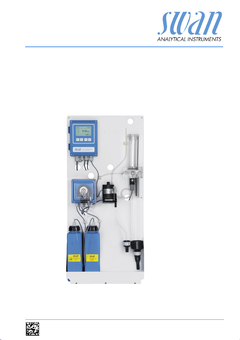
AMI Phosphate-II
Version 5.01 and higher
s Manual
Operator’
A-96.250.641 / 290312

Customer Support
SWAN and its representatives maintain a fully trained staff of technical specialists
around the world. For any technical question, contact your nearest
SWAN representative, or the manufacturer:
SWAN ANALYTISCHE INSTRUMENTE AG
Studbachstrasse 13
8340 Hinwil
Switzerland
Internet: www.swan.ch
E-mail: support@swan.ch
Document Status
Title:
ID:
Monitor AMI Phosphate-II Operator’s Manual
A-96.250.641
Revision Issue
00 July 2011 First release
01 March 2012 AMI Phosphate-II B added
© 2012, SWAN ANALYTISCHE INSTRUMENTE AG, Switzerland, all rights reserved
subject to change without notice
.

AMI Phosphate II
Table of Contents
1. Safety Instructions. . . . . . . . . . . . . . . . . . . . . . . . . . . . . 3
1.1. Warning Notices. . . . . . . . . . . . . . . . . . . . . . . . . . . . . . . . 4
1.2. General Safety Regulations . . . . . . . . . . . . . . . . . . . . . . . 6
1.3. Restrictions for use . . . . . . . . . . . . . . . . . . . . . . . . . . . . . 7
2. Product Description. . . . . . . . . . . . . . . . . . . . . . . . . . . . 8
2.1. Instrument Specification. . . . . . . . . . . . . . . . . . . . . . . . . . 12
2.2. Instrument Overview AMI Phosphate-II . . . . . . . . . . . . . . 15
2.3. Instrument Overview AMI Phosphate-II B . . . . . . . . . . . . 16
3. Installation . . . . . . . . . . . . . . . . . . . . . . . . . . . . . . . . . . . 17
3.1. Installation Check List . . . . . . . . . . . . . . . . . . . . . . . . . . . 17
3.2. Mounting of Instrument Panel . . . . . . . . . . . . . . . . . . . . . 18
3.3. Connecting Sample and Waste . . . . . . . . . . . . . . . . . . . . 18
3.4. Electrical Connections . . . . . . . . . . . . . . . . . . . . . . . . . . . 19
3.5. Connection Diagram Phosphate-II . . . . . . . . . . . . . . . . . . 21
3.6. Connection Diagram Phosphate-II B . . . . . . . . . . . . . . . . 22
3.7. Install the Cleaning Module . . . . . . . . . . . . . . . . . . . . . . . 23
3.8. Install 2nd Sample Stream. . . . . . . . . . . . . . . . . . . . . . . . 24
3.9. Power Supply . . . . . . . . . . . . . . . . . . . . . . . . . . . . . . . . . . 26
3.10. Input . . . . . . . . . . . . . . . . . . . . . . . . . . . . . . . . . . . . . . . . . 27
3.11. Relay Contacts. . . . . . . . . . . . . . . . . . . . . . . . . . . . . . . . . 27
3.11.1 Alarm Relay . . . . . . . . . . . . . . . . . . . . . . . . . . . . . . . . . . . 27
3.11.2 Relay Contacts 1 and 2 . . . . . . . . . . . . . . . . . . . . . . . . . . 27
3.12. Signal Outputs . . . . . . . . . . . . . . . . . . . . . . . . . . . . . . . . . 29
3.12.1 Signal Output 1 and 2 (current outputs) . . . . . . . . . . . . . . 29
3.12.2 Signal Output 3 (optional) . . . . . . . . . . . . . . . . . . . . . . . . 29
3.13. Interface . . . . . . . . . . . . . . . . . . . . . . . . . . . . . . . . . . . . . . 30
4. Instrument Setup . . . . . . . . . . . . . . . . . . . . . . . . . . . . . . 31
4.1. Establish Sample Flow. . . . . . . . . . . . . . . . . . . . . . . . . . . 32
4.2. Fill / Flush Reagent System . . . . . . . . . . . . . . . . . . . . . . . 33
4.3. Programming . . . . . . . . . . . . . . . . . . . . . . . . . . . . . . . . . . 33
5. Operation . . . . . . . . . . . . . . . . . . . . . . . . . . . . . . . . . . . . 34
5.1. Function of the Keys . . . . . . . . . . . . . . . . . . . . . . . . . . . . 34
5.2. Measured Values and Symbols on the Display . . . . . . . . 35
5.3. Software Structure . . . . . . . . . . . . . . . . . . . . . . . . . . . . . . 37
5.4. Changing Parameters and Values . . . . . . . . . . . . . . . . . . 38
A-96.250.641 / 230312 1

AMI Phosphate II
6. Maintenance . . . . . . . . . . . . . . . . . . . . . . . . . . . . . . . . . . 39
6.1. Maintenance Schedule. . . . . . . . . . . . . . . . . . . . . . . . . . . 39
6.2. Stop of Operation for Maintenance . . . . . . . . . . . . . . . . . 40
6.3. Refill / replace Reagents . . . . . . . . . . . . . . . . . . . . . . . . . 41
6.3.1 Reagents for Measuring Phosphate . . . . . . . . . . . . . . . . . 41
6.4. Verification . . . . . . . . . . . . . . . . . . . . . . . . . . . . . . . . . . . . 43
6.5. Calibration . . . . . . . . . . . . . . . . . . . . . . . . . . . . . . . . . . . . 44
6.6. Cleaning the protective Filter . . . . . . . . . . . . . . . . . . . . . . 45
6.7. Cleaning the Photometer . . . . . . . . . . . . . . . . . . . . . . . . . 46
6.8. Cleaning the Flow Cell . . . . . . . . . . . . . . . . . . . . . . . . . . . 47
6.8.1 Disassemble the Flow Cell . . . . . . . . . . . . . . . . . . . . . . . . 47
6.8.2 Assemble the Flow Cell . . . . . . . . . . . . . . . . . . . . . . . . . . 49
6.9. Cleaning the solenoid valve . . . . . . . . . . . . . . . . . . . . . . . 50
6.10. Tube Replacement . . . . . . . . . . . . . . . . . . . . . . . . . . . . . . 52
6.10.1 Changing Pump Tubes. . . . . . . . . . . . . . . . . . . . . . . . . . . 52
6.10.2 Tube Numbering. . . . . . . . . . . . . . . . . . . . . . . . . . . . . . . . 54
6.11. Replacing Fuses. . . . . . . . . . . . . . . . . . . . . . . . . . . . . . . . 55
6.12. Longer Stop of Operation . . . . . . . . . . . . . . . . . . . . . . . . . 56
7. Error List . . . . . . . . . . . . . . . . . . . . . . . . . . . . . . . . . . . . . 57
8. Program Overview . . . . . . . . . . . . . . . . . . . . . . . . . . . . . 61
8.1. Messages (Main Menu 1). . . . . . . . . . . . . . . . . . . . . . . . . 61
8.2. Diagnostics (Main Menu 2). . . . . . . . . . . . . . . . . . . . . . . . 62
8.3. Maintenance (Main Menu 3). . . . . . . . . . . . . . . . . . . . . . . 63
8.4. Operation (Main Menu 4) . . . . . . . . . . . . . . . . . . . . . . . . . 64
8.5. Installation (Main Menu 5) . . . . . . . . . . . . . . . . . . . . . . . . 65
9. Program List and Explanations . . . . . . . . . . . . . . . . . . 67
1 Messages . . . . . . . . . . . . . . . . . . . . . . . . . . . . . . . . . . . 67
2 Diagnostics . . . . . . . . . . . . . . . . . . . . . . . . . . . . . . . . . . 67
3 Maintenance . . . . . . . . . . . . . . . . . . . . . . . . . . . . . . . . . 69
4 Operation . . . . . . . . . . . . . . . . . . . . . . . . . . . . . . . . . . . 71
5 Installation . . . . . . . . . . . . . . . . . . . . . . . . . . . . . . . . . . . 72
10. Material Safety Data sheets. . . . . . . . . . . . . . . . . . . . . . 82
10.1. OXYCON ON-LINE phosphate reagent 1 . . . . . . . . . . . . 82
10.2. OXYCON ON-LINE phosphate reagent 2 . . . . . . . . . . . . 86
11. Default Values. . . . . . . . . . . . . . . . . . . . . . . . . . . . . . . . . 90
12. Index . . . . . . . . . . . . . . . . . . . . . . . . . . . . . . . . . . . . . . . . 92
13. Notes . . . . . . . . . . . . . . . . . . . . . . . . . . . . . . . . . . . . . . . . 93
2 A-96.250.641 / 230312

AMI Phosphate-II
Safety Instructions
AMI Phosphate-II - Operator’s Manual
This document describes the main steps for instrument setup, operation and maintenance.
1. Safety Instructions
General The instructions included in this section explain the potential risks
Targ et
audience
OM Location The AMI Operator’s Manual shall be kept in proximity of the instru-
Qualification,
Training
associated with instrument operation and provide important safety
practices designed to minimize these risks.
If you carefully follow the information contained in this section, you
can protect yourself from hazards and create a safer work environment.
More safety instructions are given throughout this manual, at the
respective locations where observation is most important.
Strictly follow all safety instructions in this publication.
Operator: Qualified person who uses the equipment
for its intended purpose.
Instrument operation requires thorough knowledge of applications,
instrument functions and software program as well as all applicable
safety rules and regulations.
ment.
To be qualified for instrument installation and operation, you must:
read and understand the instructions in this manual as well
as the Material Safety Data Sheets.
know the relevant safety rules and regulations.
A-96.250.641 / 290312 3
AMI Phosphate-II
Safety Instructions
1.1. Warning Notices
The symbols used for safety-related notices have the following significance:
WARNING
Symbols
WARNING
Generally, the triangular warning symbol indicates the possibility of personal injury or even loss of life if instructions are not followed,. e.g electrical shock hazard
Electrical shock hazard
Corrosive
Harmful to health
Flammable
Warning general
4 A-96.250.641 / 290312
AMI Phosphate-II
Safety Instructions
ATTE NTI ON
Symbols
ATT ENTI ON
The attention symbol indicates the possibility of equipment
damage, malfunctions or incorrect process results if instructions
are not followed.
Attention general
Safety goggles
Safety gloves
A-96.250.641 / 290312 5
AMI Phosphate-II
Safety Instructions
1.2. General Safety Regulations
Legal
Requirements
Spare Parts
and
Disposables
Modifications Modifications and instrument upgrades shall only be carried out by
Electrical
Shock Hazard
The user is responsible for proper system operation.
All precautions must be followed to ensure safe operation
of the instrument.
Use only official SWAN spare parts and disposables. If other parts
are used during the normal warranty period, the manufacturer’s
warranty is voided.
an authorized Service Technician. SWAN will not accept responsibility for any claim resulting from unauthorized modification or alteration.
WARNING
If proper operation is no longer possible, the instrument must be
disconnected from all power lines, and measures must be taken
to prevent inadvertent operation.
To prevent from electrical shock, always make sure that the
ground wire is connected.
Service shall be performed by authorized personnel only.
Whenever electronic service is required, disconnect
instrument power and power of devices connected to
– relay 1,
– relay 2,
– alarm relay
WARNING
For safe instrument installation and operation you must read
and understand the instructions in this manual.
WARNING
Only SWAN trained and authorized personnel shall perform the
tasks described in this document.
6 A-96.250.641 / 290312
AMI Phosphate-II
Safety Instructions
1.3. Restrictions for use
The sample must not contain any particles, which may block the
flow cell. Sufficient sample flow is coercive for the correct function
of the instrument.
If the sample contains only little disinfectant concentrations, or
there is the danger of biological growth, we recommend to use the
optional Cleaning module from Swan which is available as an option for the AMI Phosphate-II.
WARNING
For safe instrument installation and operation you must read
and understand the instructions in this manual, as well as the
Material Safety Data Sheets (MSDS)
Oxycon On-line Phosphate 1
Oxycon On-line Phosphate 2
ATT ENTI ON
Never loosen pump tubes when flow is on. Otherwise you pollute the reagents.
A-96.250.641 / 290312 7

AMI Phosphate-II
Product Description
2. Product Description
Application This manual describes the functions of the analyzers:
AMI Phosphate-II
AMI Phosphate-II B
Both analyzers are complete monitoring systems for the automatic
continuous measurement of ortho-Phosphate. ortho-Phosphate
can be found in many applications like corrosion protection in sanitary systems and boilers or as additive to detergents. On-line measurement is used in quality control of drinking water, waste water
plants and thermal power plants.
Measuring
principle
Programmable
Measuring
Intervals
Signal
Outputs
Relay Two potential-free contact programmable as limit switches for mea-
The measurement is based on the molybdenum blue colorimetric
method according to APHA 4500-P E. and on EN ISO 6878. When
the reaction product of o-phosphate with ammonium-molybdate is
reduced with ascorbic acid, the intensely colored molybdenum blue
is formed. The color intensity is proportional to the o-phosphate
concentration of the sample and is measured photometrically at
815 nm.
The duration of a measuring interval can be set to:
10 min (not available if “2 Channels” is selected)
15 min
20 min
30 min
Independent of the programmed measuring interval, the measurement time of a sample takes 7 minutes.
Two signal outputs programmable for measured values (freely scalable, linear or bilinear) or as continuous control output (control parameters programmable).
Current loop: 0/4 – 20 mA
Maximal burden: 510
Third signal output with the same specifications as option.
(Only possible if no communication interface is used.)
suring values, controllers or timer for system cleaning with automatic hold function.
Maximum load: 1 A/250 VAC
8 A-96.250.641 / 290312
AMI Phosphate-II
Product Description
Alarm Relay One potential free contact.
Alternatively:
Open during normal operation, closed on error and loss of
power.
Closed during normal operation, open on error and loss of
power.
Summary alarm indication for programmable alarm values
and instrument faults.
Input One potential-free contact to freeze the measuring value or to inter-
Safety
Features
Communica-
tion Interface
(optional)
nd
2
Sample
Stream
Cleaning
Module
rupt control in automated installations (hold function or remote-off).
The potential-free contact is located:
at the AMI Phosphate-II in the AMI Transmitter
at the AMI Phosphate-II B in the peristaltic pump
No data loss after power failure. All data is saved in non-volatile
memory. Over voltage protection of in- and outputs.Galvanic separation of measuring inputs and signal outputs.The analyzer is factory tested and ready for installation and operation.
RS232 for logger download with HyperTerminal or RS485 with
Fieldbus protocol Modbus or Profibus DP. Webserver connection
via Modbus.
AMI Phosphate-II B
As an option an inlet for two sample streams with a sample switch-
ing valve can be installed onto the panel of the AMI Phosphate-II B
AMI Phosphate-II
As an option a cleaning module is available which can be connect-
ed to the AMI Phosphate-II.
WARNING
The drain of the photometer outlet contains Hexammonium
heptamolybdate 4-hydrate.
At no means recirculate it into the water system.
A-96.250.641 / 290312 9

AMI Phosphate-II
Product Description
On-line
operation
Calibration Close the flow regulating valve to drain the constant head. Prepare
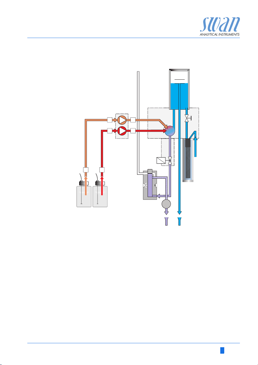
The sample flows through the sample inlet [K] and the filter vessel
[J] into the constant head [A]. Adjust the flow regulating valve so
that always a small part of the sample flows through the overflow
tube [B] into the drain [R]. This adjustment ensures a sufficient
sample flow through the measuring chamber of the photometer [M].
If no measurement takes place, the sample flows through the outlet
of the photometer where it will be aerated through air inlet [H] to
generate bubbles. Then the sample flows through the bubble counter [P] into the waste [Q].
If a measuring cycle starts:
1 A zero measurement with the sample is performed before the
reagents are added.
2 The peristaltic pump [C] pumps the reagents [N] and [O] into the
mixing chamber [G] where they are mixed together with the
sample and then flowing through the photometer [M].
3 The solenoid valve [I] will be activated to close the inlet of the
photometer.
4 The sample remains in the photometer for 7 minutes. During
this time a reaction with the reagents takes place.
5 After the 7 min have elapsed a second measurement is carried
out and the o-phosphate concentration is calculated.
6 If the measurement has been finished, the solenoid valve will be
deactivated to open the inlet of the photometer.
7 The sample flows through the outlet of the photometer where it
will be aerated to generate bubbles.
8 The sample flows through the bubble detector [P] and into the
waste [Q].
a standard solution with deionized water and fill it into the constant
head. A normal measuring cycle is then initialized, the measured
value is used to calculate the photometer's slope. For details see
Calibration, S. 44.
10 A-96.250.641 / 290312
AMI Phosphate-II
Product Description
Fluidics
A
B
C
3
4
4
3
LL M
NO P
A
Constant head
B
Overflow tube
C
Peristaltic pump
D
Flow cell block
E
Sample flow to mixing
1
2
HI
chamber
F
Flow regulating valve
G
Mixing chamber
H
Air inlet
I
Solenoid valve
D
QR
J
K
L
M
N
O
P
Q
R
E
F
G
JK
Filter vessel
Sample inlet
Reagent level detectors
Photometer
Oxycon on-line Phosphate 1
Oxycon on-line Phosphate 2
Bubble detector
Waste
Drain
A-96.250.641 / 290312 11
AMI Phosphate-II
Product Description
2.1. Instrument Specification
Power Supply Voltage: 100–240 VAC (± 10%)
50/60 Hz (± 5%)
or 24 VDC, isolated, (± 15%)
Power consumption: max. 20 VA
Sample
requirements
Flow rate: min. 10 l/h
Sample pressure inlet: 0.15–2 bar (2 – 28 PSI)
Temperature: 5–50 °C (41 – 122 °F)
ATTE NTI ON
No oil, no grease, no sand.
On-site
requirements
Electronics
housing
The analyzer site must permit connections to:
Sample inlet: Tube 4 x 6 mm
2 Drains: each 15 x 20 mm
(1/2”) hose nozzle which must end in convenient atmospheric
waste of sufficient capacity.
Aluminum
with a protection degree of IP 66 / NEMA 4X
Ambient temperature: -10 to +50 °C
Limit range of operation: -25 to +65 °C
Storage and transport: -30 to +85 °C
Humidity.: 10 to 90 % relative non condensing
Display: backlit LCD, 75 mm x 45 mm
12 A-96.250.641 / 290312
AMI Phosphate-II
AMI Phosphate-II
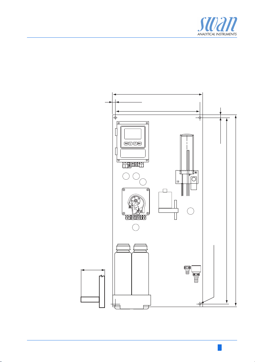
824 mm / 32
7
/
16
”
850 mm / 33½”
13 mm / ½”
400 mm / 15¾”
374 mm / 14¾”
13 mm / ½”
4 x dia. 6.5 mm / ¼”
30 mm / 1 ”
3
16
/
Product Description
Dimensions
Phosphate-II
Panel PVC: 400 x 850 mm
Mounting hole distance: 374 x 824 mm
Screws: 5 mm or 6 mm diam.
Weight: 9.0 kg /19.9 lbs
A-96.250.641 / 290312 13
AMI Phosphate-II
AMI Phosphate-II
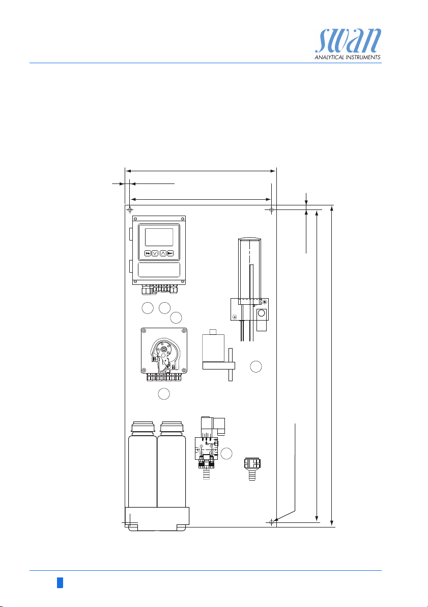
824 mm / 32
7
/
16
”
850 mm / 33½”
13 mm / ½”
400 mm / 15¾”
374 mm / 14¾”
13 mm / ½”
4 x dia. 6.5 mm / ¼”
Product Description
Dimensions
Phosphate-II B
Panel stainless steel: 400 x 850 mm
Mounting hole distance: 374 x 824 mm
Screws: 5 mm or 6 mm diam.
Weight: 14.0 kg /30.85 lbs
14 A-96.250.641 / 290312
AMI Phosphate-II
Product Description
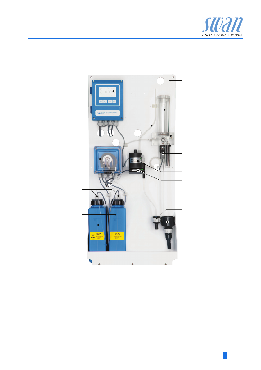
2.2. Instrument Overview AMI Phosphate-II
O
N
A
B
C
D
E
F
G
H
I
M
L
A
Panel PVC
B
Transmitter
C
Constant head
D
Air inlet pipe
E
Flow cell block
F
Sample inlet with filter vessel
G
Solenoid valve
H
Photometer
A-96.250.641 / 290312 15
I
J
K
L
M
N
O
J
K
Bubble detector
Waste funnel for sample
Drain
Oxycon on-line Phosphate 1
Oxycon on-line Phosphate 2
Reagent level detectors
Peristaltic pump
AMI Phosphate-II
Product Description
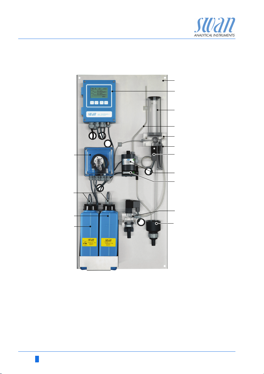
2.3. Instrument Overview AMI Phosphate-II B
O
N
A
B
C
D
E
F
G
H
I
M
L
A
Panel stainless steel
B
Transmitter
C
Constant head
D
Air inlet pipe
E
Flow cell block
F
Sample inlet with filter vessel
G
Solenoid valve
H
Photometer
I
J
K
L
M
N
O
J
K
Bubble detector
nd
sample stream (option)
2
Waste
Oxycon on-line Phosphate 1
Oxycon on-line Phosphate 2
Reagent level detectors
Peristaltic pump
16 A-96.250.641 / 290312
AMI Phosphate-II
Installation
3. Installation
3.1. Installation Check List
Check Instrument’s specification must conform to your AC power ratings.
Do not turn on power until instructed to do so.
On site requirements
Installation Mount the instrument in vertical position.
Electrical Wiring Connect all external devices like limit switches, current loops and
Reagents Prepare reagents. See 6.3.1, 41
Power-up Perform exactly in this order:
Instrument
Setup
Run-in period Let the instrument run continuously for 1 h.
100–240 VAC ( 10%), 50/60 Hz ( 5%) or 24 VDC (±15%),
isolated power outlet with ground connection and 20 VA.
Sample line with min. 10 l/h and 0.15–2 bar.
Waste line with atmospheric drain.
Display should be at eye-level.
Mount the filter, filter vessel, and constant head.
Connect the sample and waste line. See Connecting Sample and
Waste, S. 18
pumps.
Connect power cord; do NOT switch on power yet!
See Electrical Connections, S. 19
Insert suction lance/level detectors.
– Lock the occlusion frames of the peristaltic pump.
The peristaltic pump is ready
– Turn on the sample flow and wait until the flow cell is completely
filled. Fill system. See 4.2., 33
– Switch on power.
Program all parameters for external devices (interface, recorders,
etc.). Program all parameters for instrument operation (limits,
alarms).
A-96.250.641 / 290312 17
AMI Phosphate-II
B
C
D
A
Installation
3.2. Mounting of Instrument Panel
Mount the instrument in vertical position. For ease of operation
mount it so that the display is at eye-level. For dimensions see picture Dimensions Phosphate-II, S. 13
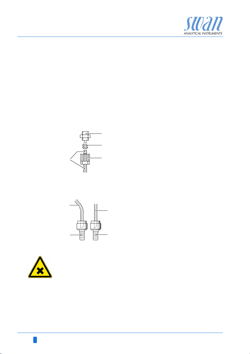
3.3. Connecting Sample and Waste
Sample inlet Use plastic tube (FEP, PA, or PE 4 x 6 mm) to connect the sample
Mounting of
SERTO fitting
Waste Connect the 1/2” tubes to the nozzle of the waste funnels and place
line. See also , S. 30
A
Screw connection
B
Compression ferrule
C
Knurled nut
D
Flexible tube
them into an atmospheric drain of sufficient capacity.
A
A
B
WARNING
the sample which flows after the measurement through the outlet of the photometer contains Hexammonium heptamolybdate
4-hydrate.
At no means recirculate it into the water system.
Tube from photometer
B
Waste (photometer)
C
C
Tube from constant head
D
Drain (constant head)
D
18 A-96.250.641 / 290312
AMI Phosphate-II
Installation
3.4. Electrical Connections
WARNING
Always turn off AC power before manipulating electric parts.
Grounding requirements: Only operate the instrument from an
power outlet which has a ground connection.
Make sure the power specification of the instrument corresponds to the power on site.
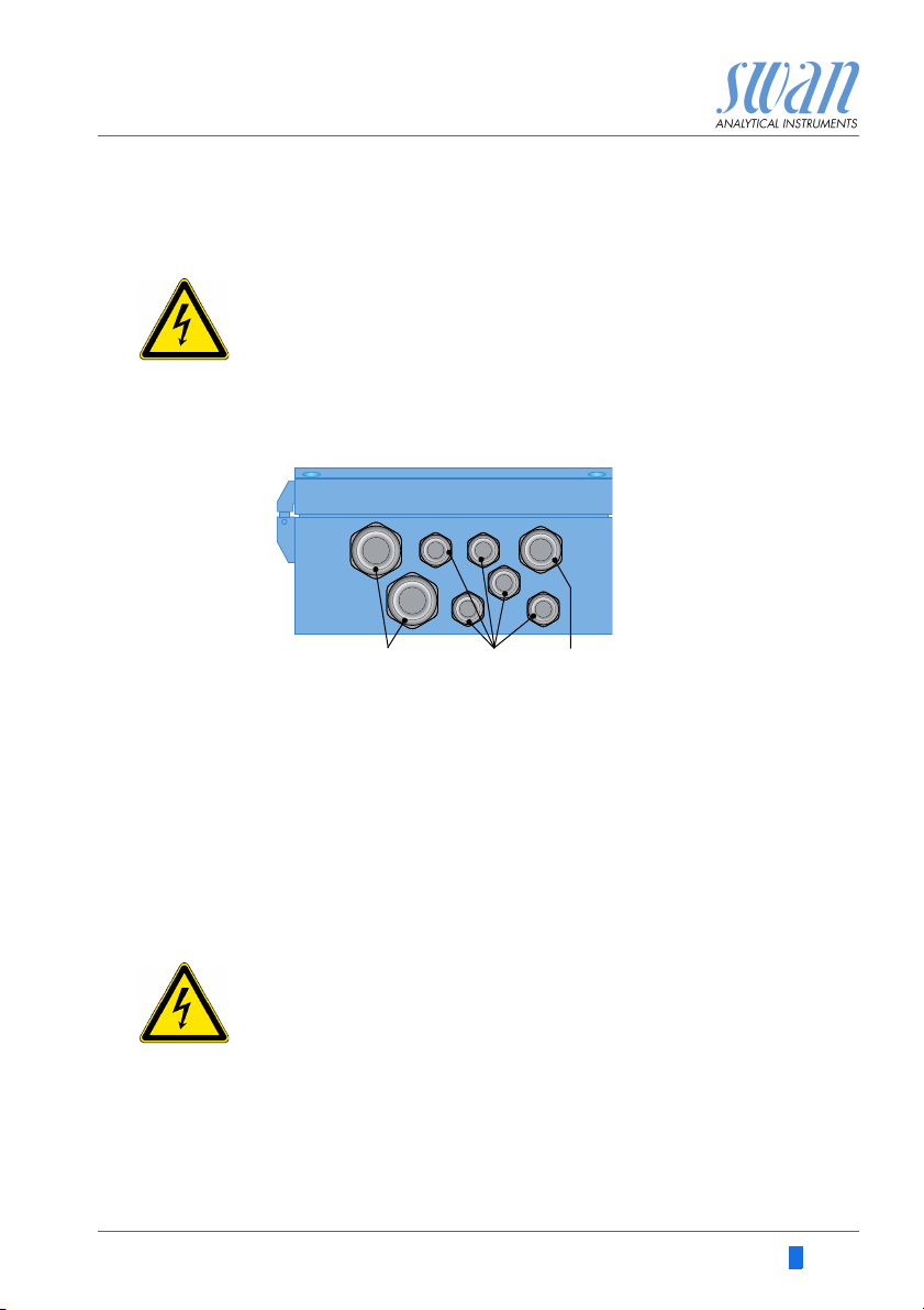
Cable
thicknesses
In order to comply with IP66, use the following cable thicknesses
PG 11 cable gland: cable Ø
A
B
PG 7 cable gland: cable Ø
C
PG 9 cable gland: cable Ø
ABC
5–10 mm
outer
3–6.5 mm
outer
4–8 mm
outer
Note: Protect unused cable glands
2
Wire For Power and Relays: Use max. 1.5 mm
/ AWG 14 strand-
ed wire with end sleeves.
For Signal Outputs and Input: Use 0.25 mm
2
/ AWG 23
stranded wire with end sleeves.
WARNING
Make sure that the devices to be connected to
relay 1
relay 2
alarm relay
are disconnected from the power before resuming installation.
A-96.250.641 / 290312 19
AMI Phosphate-II
Installation
WARNING
To prevent from electrical shock, do not connect the instrument
to the power unless the ground wire (PE) is connected.
Do not connect unless specifically instructed to do so.
WARNING
The mains of the AMI Transmitter must be secured by a main
switch and appropriate fuse or circuit breaker.
20 A-96.250.641 / 290312
AMI Phosphate-II
Installation
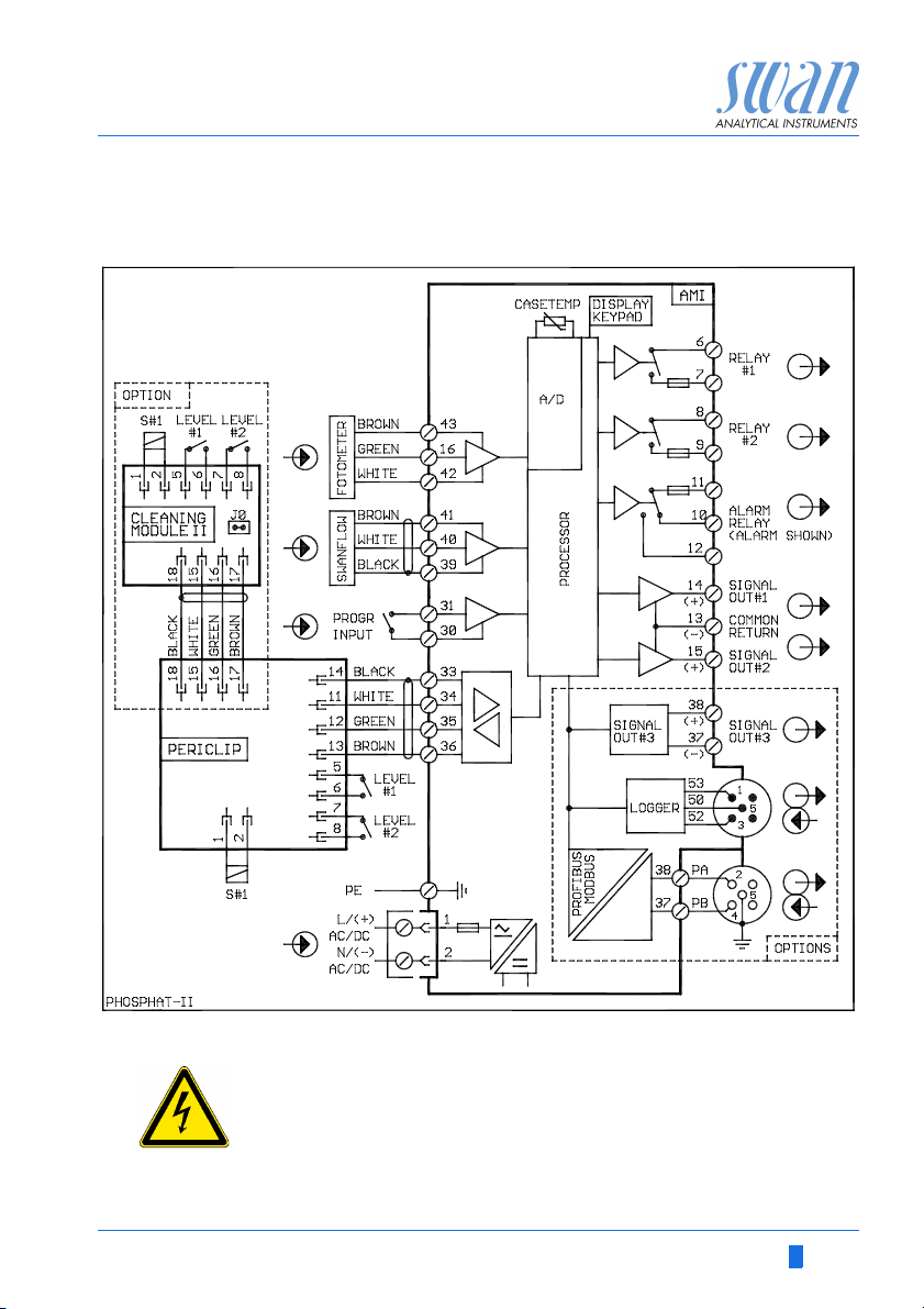
3.5. Connection Diagram Phosphate-II
WARNING
Use only the terminals shown in this diagram, and only for the
mentioned purpose. Use of any other terminals will cause short
circuits with possible corresponding consequences to material
and personnel.
A-96.250.641 / 290312 21
AMI Phosphate-II
Installation
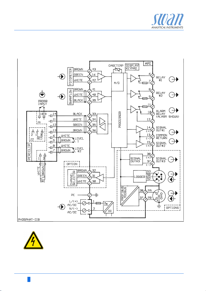
3.6. Connection Diagram Phosphate-II B
WARNING
Use only the terminals shown in this diagram, and only for the
mentioned purpose. Use of any other terminals will cause short
circuits with possible corresponding consequences to material
and personnel.
22 A-96.250.641 / 290312
AMI Phosphate-II
Installation
3.7. Install the Cleaning Module
The optional cleaning module can only be used together with the
AMI Phosphate-II.
For installation and commissioning of the cleaning module consult
the manual of the cleaning module.
A-96.250.641 / 290312 23
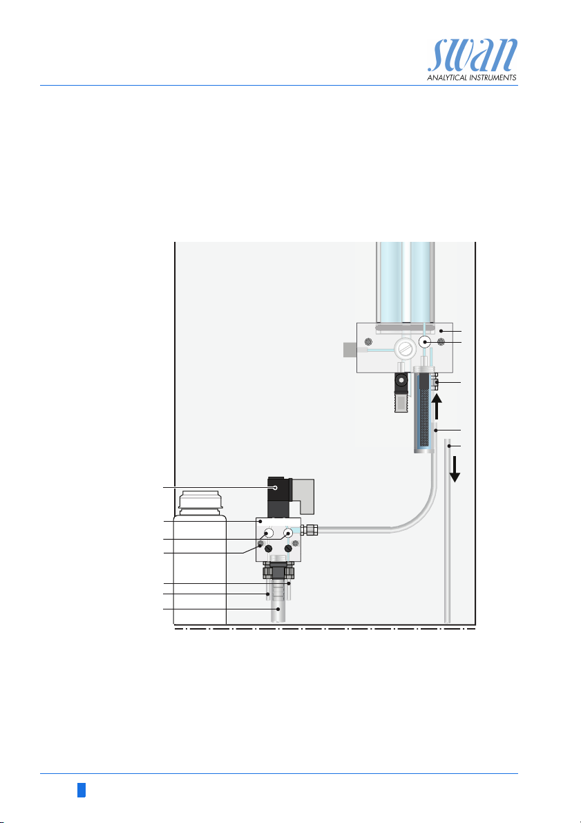
AMI Phosphate-II
2
1
A
B
C
D
E
F
G
H
I
J
K
L
Installation
3.8. Install 2nd Sample Stream
The 2nd sample stream option is only available for the
AMI Phosphate-II B.
The following description assumes that the installation of the
nd
2
sample stream takes place after commissioning of the monitor.
A
Flow cell block
B
24 A-96.250.641 / 290312
Flow regulating valve
C
Sample inlet
D
Sample inlet tube from
nd
sample stream option
2
Sample inlet tube
E
Solenoid valve
F
nd
sample stream option
G
2
Flow regulating valves
H
Fixing screws
I
Sample inlet 1
J
Sample inlet 2
K
Overflow tube
L
AMI Phosphate-II
BA
Installation
Sample
Connection
Electrical
Connection
1 Stop sample flow.
2 Switch off the instrument.
3 Empty the flow cell.
4 Remove the sample inlet tube [E] from the flow cell block [A].
5 Screw the 2
screws (I) to the panel.
6 Install the tube [D] between the 2nd sample stream option and
the flow cell block.
7 Connect sample inlet 1 (J) and sample inlet 2 (K) to the
corresponding inlets at the 2
8 Connect the overflow tube (L) to the drain.
WARNING
Electrical shock hazard!
Before opening the AMI Transmitter switch power off.
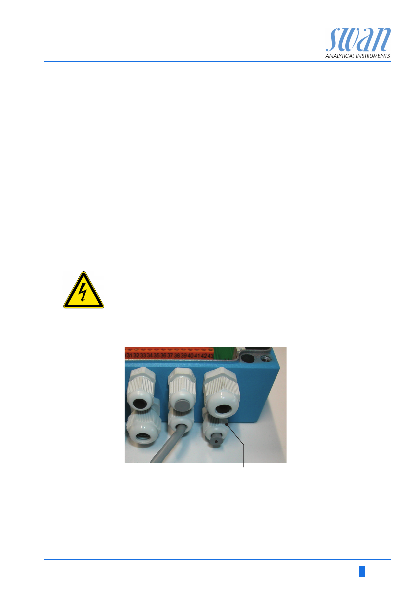
Use one of the PG7 cable glands to feed the cable of the solenoid
valve into the AMI transmitter housing.
nd
sample stream option (G) with the two fixing
nd
sample stream option.
1 Remove the plug [A] from the cable gland [B.
2 Feed the cable of the solenoid valve through the cable gland (B)
into the AMI transmitter housing.
3 Connect the wires to the terminals in the AMI transmitter
according to the Connection Diagram Phosphate-II B, S. 22.
A-96.250.641 / 290312 25
AMI Phosphate-II
A
B
C
D
Installation
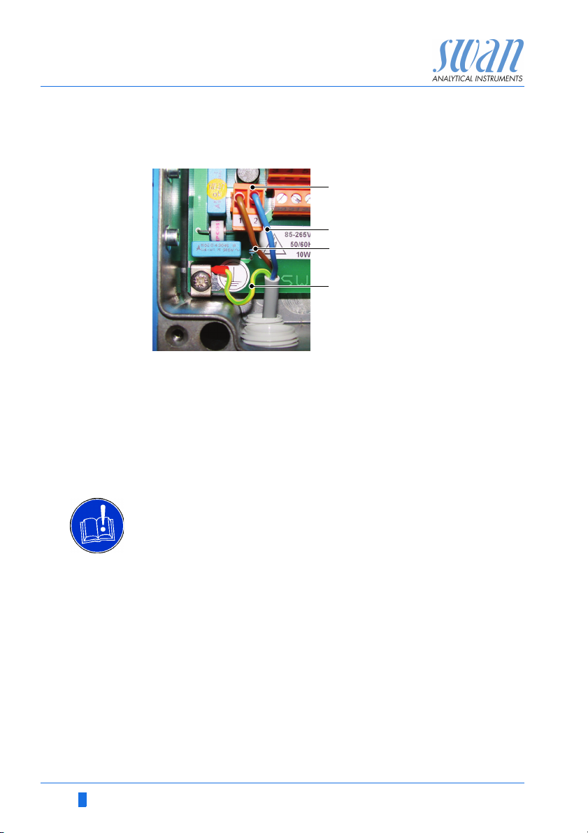
3.9. Power Supply
A
Power supply connector
B
Neutral N, Terminal 2
C
Outer conductor L, Terminal 1
D
Protective earth PE
Note: The protective earth wire (Ground) has to be connected
to the grounding terminal.
ATTE NTI ON
It is not allowed to power external loads out of the
AMI transmitter.
Instrument power supply:
Only a certified electrician shall connect the instrument to
the mains.
Fuse 1 AT
Mains cable to comply with standards IEC 60227 or IEC
60245; flammable rating FV1
Mains equipped with an external switch or circuit-breaker
- near the instrument,
- easily accessible to the operator,
- marked as interrupter for AMI Phosphate-II
26 A-96.250.641 / 290312
AMI Phosphate-II
Installation
3.10. Input
Note: Use only potential-free (dry) contacts.
• Terminals 30/ 31 at AMI Phosphate-II transmitter
• Terminals 9/ 10 at AMI Phosphate-II B peristaltic pump
If signal output is set to hold, measurement is interrupted if input is
active.
For programming see menu 5.3.4, S. 82
3.11. Relay Contacts
Programming of the relay contacts see 5.3 Relay Contacts, S. 78
3.11.1 Alarm Relay
Note: Max. load 1 AT / 250 VAC
Alarm output for system errors.
Error codes see Error List, S. 60
Programming see menu 5.3.1, S. 78
Term ina ls Description
Normally
open
Normally
closed
a) usual use
10 / 11 Opened during normal operation.
a)
12 / 11 Closed during normal operation.
Closed on error and loss of power.
Opened on error and loss of power.
3.11.2 Relay Contacts 1 and 2
Note: Rated load 1 AT / 250 VAC
Relay 1: Terminals 6/7
Relay 2: Terminals 8/9
Programming see menu 5.3.2/3, S. 80
A-96.250.641 / 290312 27
 Loading...