

Page 1
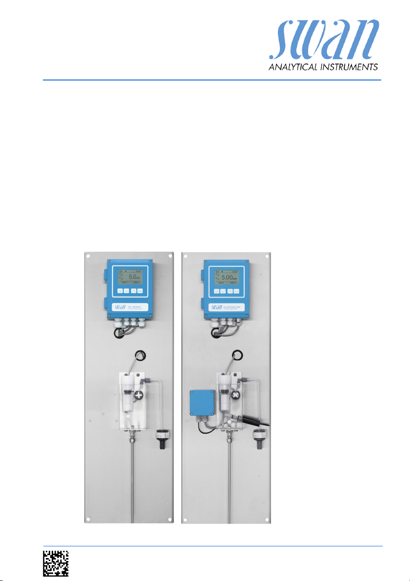
AMI Oxytrace
AMI Oxytrace QED
Version 6.20 and higher
or’s Manual
Operat
A-96.250.531 / 300617
Page 2

Customer Support
SWAN and its representatives maintain a fully trained staff of technical specialists
around the world. For any technical question, contact your nearest
SWAN representative, or the manufacturer:
SWAN ANALYTISCHE INSTRUMENTE AG
Studbachstrasse 13
8340 Hinwil
Switzerland
Internet: www.swan.ch
E-mail: support@swan.ch
Document Status
Title:
ID:
Monitor AMI Oxytrace QED Operator’s Manual
A-96.250.531
Revision Issue
00 Jan. 2008 First Edition
01 Nov. 2008 Including AMI Oxytrace QED
02 July 2011 Chapter Quality Assurance added
03 Oct. 2013 New mainboard V2.4, update to FW Release 5.4
04 Sept. 2016 New mainboard V2.5, update to FW Release 6.20
© 2016, SWAN ANALYTISCHE INSTRUMENTE AG, Switzerland, all rights reserved
subject to change without notice.
Page 3

AMI Oxytrace QED
Table of Contents
1. Safety Instructions . . . . . . . . . . . . . . . . . . . . . . . . . . . . . . . . . . . 4
1.1. Warning Notices . . . . . . . . . . . . . . . . . . . . . . . . . . . . . . . . . . . . . . 5
1.2. General Safety Regulations . . . . . . . . . . . . . . . . . . . . . . . . . . . . . 7
2. Product Description . . . . . . . . . . . . . . . . . . . . . . . . . . . . . . . . . . 8
2.1. Description of the System. . . . . . . . . . . . . . . . . . . . . . . . . . . . . . . 8
2.2. Technical Data . . . . . . . . . . . . . . . . . . . . . . . . . . . . . . . . . . . . . . . 13
2.3. Instrument Overview. . . . . . . . . . . . . . . . . . . . . . . . . . . . . . . . . . . 15
2.4. Single Components . . . . . . . . . . . . . . . . . . . . . . . . . . . . . . . . . . . 17
2.4.1 AMI Oxytrace Transmitter. . . . . . . . . . . . . . . . . . . . . . . . . . . . . . . 17
2.4.2 Sensor OXYTRACE G . . . . . . . . . . . . . . . . . . . . . . . . . . . . . . . . . 18
2.4.3 QV-Flow PMMA OTG . . . . . . . . . . . . . . . . . . . . . . . . . . . . . . . . . . 19
2.4.4 B-Flow SS316L OTG . . . . . . . . . . . . . . . . . . . . . . . . . . . . . . . . . . 20
3. Installation. . . . . . . . . . . . . . . . . . . . . . . . . . . . . . . . . . . . . . . . . . 21
3.1. Installation Check List. . . . . . . . . . . . . . . . . . . . . . . . . . . . . . . . . . 21
3.2. Mounting of Instrument Panel. . . . . . . . . . . . . . . . . . . . . . . . . . . . 22
3.3. Connecting Sample Inlet and Outlet. . . . . . . . . . . . . . . . . . . . . . . 23
3.3.1 Swagelok Fitting Stainless Steel at Sample Inlet . . . . . . . . . . . . . 23
3.3.2 FEP Tube at Sample Outlet . . . . . . . . . . . . . . . . . . . . . . . . . . . . . 24
3.4 Install the Swansensor Oxytrace G . . . . . . . . . . . . . . . . . . . . . . . 24
3.5. Electrical Connections . . . . . . . . . . . . . . . . . . . . . . . . . . . . . . . . . 25
3.5.1 Electrical Connection Diagram AMI Oxytrace . . . . . . . . . . . . . . . 27
3.5.2 Electrical Connection Diagram AMI Oxytrace QED . . . . . . . . . . . 28
3.5.3 Power Supply . . . . . . . . . . . . . . . . . . . . . . . . . . . . . . . . . . . . . . . . 29
3.6. Input . . . . . . . . . . . . . . . . . . . . . . . . . . . . . . . . . . . . . . . . . . . . . . . 30
3.7. Relay Contacts . . . . . . . . . . . . . . . . . . . . . . . . . . . . . . . . . . . . . . . 30
3.7.1 Alarm Relay . . . . . . . . . . . . . . . . . . . . . . . . . . . . . . . . . . . . . . . . . 30
3.7.2 Relay 1 and 2 . . . . . . . . . . . . . . . . . . . . . . . . . . . . . . . . . . . . . . . . 31
3.8. Signal Outputs . . . . . . . . . . . . . . . . . . . . . . . . . . . . . . . . . . . . . . . 33
3.8.1 Signal output 1 and 2 (current outputs) . . . . . . . . . . . . . . . . . . . . 33
3.9. Interface Options . . . . . . . . . . . . . . . . . . . . . . . . . . . . . . . . . . . . . 33
3.9.1 Signal Output 3. . . . . . . . . . . . . . . . . . . . . . . . . . . . . . . . . . . . . . . 34
3.9.2 Profibus, Modbus Interface. . . . . . . . . . . . . . . . . . . . . . . . . . . . . . 34
3.9.3 HART Interface. . . . . . . . . . . . . . . . . . . . . . . . . . . . . . . . . . . . . . . 35
3.9.4 USB Interface . . . . . . . . . . . . . . . . . . . . . . . . . . . . . . . . . . . . . . . . 35
4. Instrument Setup . . . . . . . . . . . . . . . . . . . . . . . . . . . . . . . . . . . . 36
4.1. Establish Sample Flow . . . . . . . . . . . . . . . . . . . . . . . . . . . . . . . . . 36
4.2. Programming . . . . . . . . . . . . . . . . . . . . . . . . . . . . . . . . . . . . . . . . 36
A-96.250.531 / 300617 1
Page 4

AMI Oxytrace QED
5. Operation. . . . . . . . . . . . . . . . . . . . . . . . . . . . . . . . . . . . . . . . . . . 37
5.1. Keys . . . . . . . . . . . . . . . . . . . . . . . . . . . . . . . . . . . . . . . . . . . . . . . 37
5.2. Display . . . . . . . . . . . . . . . . . . . . . . . . . . . . . . . . . . . . . . . . . . . . . 38
5.3. Software Structure . . . . . . . . . . . . . . . . . . . . . . . . . . . . . . . . . . . . 39
5.4. Changing Parameters and values. . . . . . . . . . . . . . . . . . . . . . . . . 40
6. Maintenance . . . . . . . . . . . . . . . . . . . . . . . . . . . . . . . . . . . . . . . . 41
6.1. Maintenance Table . . . . . . . . . . . . . . . . . . . . . . . . . . . . . . . . . . . . 41
6.2. Stop of Operation for Maintenance. . . . . . . . . . . . . . . . . . . . . . . . 41
6.3. Maintenance of the Oxygen Sensor . . . . . . . . . . . . . . . . . . . . . . . 42
6.3.1 Electrolyte exchange. . . . . . . . . . . . . . . . . . . . . . . . . . . . . . . . . . . 42
6.3.2 Clean Swansensor Oxytrace G and Flow Cell . . . . . . . . . . . . . . . 44
6.4. Maintenance of the Faraday electrode . . . . . . . . . . . . . . . . . . . . . 45
6.5. Calibration. . . . . . . . . . . . . . . . . . . . . . . . . . . . . . . . . . . . . . . . . . . 47
6.6. Zero-Verification . . . . . . . . . . . . . . . . . . . . . . . . . . . . . . . . . . . . . . 49
6.7. Faraday Verification . . . . . . . . . . . . . . . . . . . . . . . . . . . . . . . . . . . 50
6.8. Quality Assurance of the Instrument. . . . . . . . . . . . . . . . . . . . . . . 51
6.8.1 Activate SWAN Quality assurance procedure . . . . . . . . . . . . . . . 52
6.8.2 Pre-test . . . . . . . . . . . . . . . . . . . . . . . . . . . . . . . . . . . . . . . . . . . . . 53
6.8.3 Connect the sample lines . . . . . . . . . . . . . . . . . . . . . . . . . . . . . . . 53
6.8.4 Carry out comparison measurement. . . . . . . . . . . . . . . . . . . . . . . 55
6.8.5 Completion of the measurement. . . . . . . . . . . . . . . . . . . . . . . . . . 56
6.9. Replacing Fuses . . . . . . . . . . . . . . . . . . . . . . . . . . . . . . . . . . . . . . 57
6.10. Longer Stop of Operation . . . . . . . . . . . . . . . . . . . . . . . . . . . . . . . 58
7. Error List . . . . . . . . . . . . . . . . . . . . . . . . . . . . . . . . . . . . . . . . . . . 59
8. Program Overview . . . . . . . . . . . . . . . . . . . . . . . . . . . . . . . . . . . 63
8.1. Messages (Main Menu 1) . . . . . . . . . . . . . . . . . . . . . . . . . . . . . . . 63
8.2. Diagnostics (Main Menu 2) . . . . . . . . . . . . . . . . . . . . . . . . . . . . . . 64
8.3. Maintenance (Main Menu 3) . . . . . . . . . . . . . . . . . . . . . . . . . . . . . 65
8.4. Operation (Main Menu 4) . . . . . . . . . . . . . . . . . . . . . . . . . . . . . . . 66
8.5. Installation (Main Menu 5). . . . . . . . . . . . . . . . . . . . . . . . . . . . . . . 67
9. Program List and Explanations. . . . . . . . . . . . . . . . . . . . . . . . . 69
1 Messages. . . . . . . . . . . . . . . . . . . . . . . . . . . . . . . . . . . . . . . . . . 69
2 Diagnostics . . . . . . . . . . . . . . . . . . . . . . . . . . . . . . . . . . . . . . . . 69
3 Maintenance . . . . . . . . . . . . . . . . . . . . . . . . . . . . . . . . . . . . . . . 71
4 Operation . . . . . . . . . . . . . . . . . . . . . . . . . . . . . . . . . . . . . . . . . . 73
5 Installation . . . . . . . . . . . . . . . . . . . . . . . . . . . . . . . . . . . . . . . . . 74
10. Material Safety Data sheets . . . . . . . . . . . . . . . . . . . . . . . . . . . . 89
10.1. Reagents. . . . . . . . . . . . . . . . . . . . . . . . . . . . . . . . . . . . . . . . . . . . 89
2 A-96.250.531 / 300617
Page 5

AMI Oxytrace QED
11. Default Values. . . . . . . . . . . . . . . . . . . . . . . . . . . . . . . . . . . . . . . 90
12. Index . . . . . . . . . . . . . . . . . . . . . . . . . . . . . . . . . . . . . . . . . . . . . . 93
13. Notes . . . . . . . . . . . . . . . . . . . . . . . . . . . . . . . . . . . . . . . . . . . . . . 94
A-96.250.531 / 300617 3
Page 6

AMI Oxytrace QED
Safety Instructions
AMI Oxytrace QED Operator’s Manual
This document describes the main steps for instrument setup, operation and maintenance.
1. Safety Instructions
General The instructions included in this section explain the potential risks
associated with instrument operation and provide important safety
practices designed to minimize these risks.
If you carefully follow the information contained in this section, you
can protect yourself from hazards and create a safer work environment.
More safety instructions are given throughout this manual, at the
respective locations where observation is most important.
Strictly follow all safety instructions in this publication.
Target
audience
OM Location The AMI Operator’s Manual shall be kept in proximity of the instru-
Qualification,
Training
Operator: Qualified person who uses the equipment
for its intended purpose.
Instrument operation requires thorough knowledge of applications,
instrument functions and software program as well as all applicable
safety rules and regulations.
ment.
To be qualified for instrument installation and operation, you must:
read and understand the instructions in this manual as well as
the Material Safety Data Sheets.
know the relevant safety rules and regulations.
4 A-96.250.531 / 300617
Page 7
AMI Oxytrace QED
Safety Instructions
1.1. Warning Notices
The symbols used for safety-related notices have the following significance:
DANGER
Your life or physical wellbeing are in serious danger if such
warnings are ignored.
Follow the prevention instructions carefully.
WARNING
Severe injuries or damage to the equipment can occur if such
warnings are ignored.
Follow the prevention instructions carefully.
CAUTION
Damage to the equipment, minor injury, malfunctions or incorrect process can be the consequence if such warnings are ignored.
Follow the prevention instructions carefully.
Mandatory
Signs
A-96.250.531 / 300617 5
The importance of the mandatory signs in this manual.
Safety goggles
Safety gloves
Page 8
AMI Oxytrace QED
Safety Instructions
Warning Signs The importance of the warning signs in this manual.
Electrical shock hazard
Corrosive
Harmful to health
Flammable
Warning general
Attention general
6 A-96.250.531 / 300617
Page 9
AMI Oxytrace QED
Safety Instructions
1.2. General Safety Regulations
Legal
Requirements
Spare Parts
and
Disposables
Modifications Modifications and instrument upgrades shall only be carried out by
The user is responsible for proper system operation.
All precautions must be followed to ensure safe operation
of the instrument.
Use only official SWAN spare parts and disposables. If other parts
are used during the normal warranty period, the manufacturer’s
warranty is voided.
an authorized Service Technician. SWAN will not accept responsibility for any claim resulting from unauthorized modification or alteration.
WARNING
Risk of Electrical Shock
If proper operation is no longer possible, the instrument must be
disconnected from all power lines, and measures must be taken
to prevent inadvertent operation.
To prevent from electrical shock, always make sure that the
ground wire is connected.
Service shall be performed by authorized personnel only.
Whenever electronic service is required, disconnect instru-
ment power and power of devices connected to.
– relay 1,
– relay 2,
– alarm relay
WARNING
For safe instrument installation and operation you must read
and understand the instructions in this manual.
WARNING
Only SWAN trained and authorized personnel shall perform the
tasks described in this document.
A-96.250.531 / 300617 7
Page 10

AMI Oxytrace QED
Product Description
2. Product Description
This manual describes the functions of the following monitors
AMI Oxytrace
AMI Oxytrace QED
Both monitors are mainly identical except that AMI Oxytrace QED
includes a faraday verification.
2.1. Description of the System
Application AMI Oxytrace is used to measure low levels of oxygen in high-puri-
ty water. Especially in power plant water cycles (e.g. feedwater), a
very low level of oxygen is needed to prevent corrosion.
Measuring
principle
Clark principle:
The sensor consists of one noble metal electrode (e.g. platinum or
gold), a reference electrode (mostly Ag/AgCl) and optionally a metal guard electrode.
The Clark-type electrode is the most widely used oxygen sensor for
measuring oxygen dissolved in a liquid. The basic principle is that
there is a cathode and an anode submersed in an electrolyte and a
voltage is applied between the two parts. Oxygen enters the sensor
through a permeable membrane by diffusion, and is reduced at the
cathode according to
O
+ 4e- + 2 H2O --> 4 OH
2
This reaction creates a measurable current. There is a linear correlation between the oxygen concentration and the electrical current.
The guard electrode is on the same voltage level as the cathode
but there is no current measurement. Oxygen which diffuses from
the electrolyte to the cathode is consumed by the guard electrode.
As a consequence, residual oxygen in the electrolyte will no more
disturb the measurement signal and the response time to low oxygen levels will be shorter.
-
Temperature
compensa-
tion
The measuring signal depends on temperature, but is automatically
compensated to 25 °C. The sample temperature is determined continuously by a temperature sensor inside the oxygen electrode.
8 A-96.250.531 / 300617
Page 11
AMI Oxytrace QED
Product Description
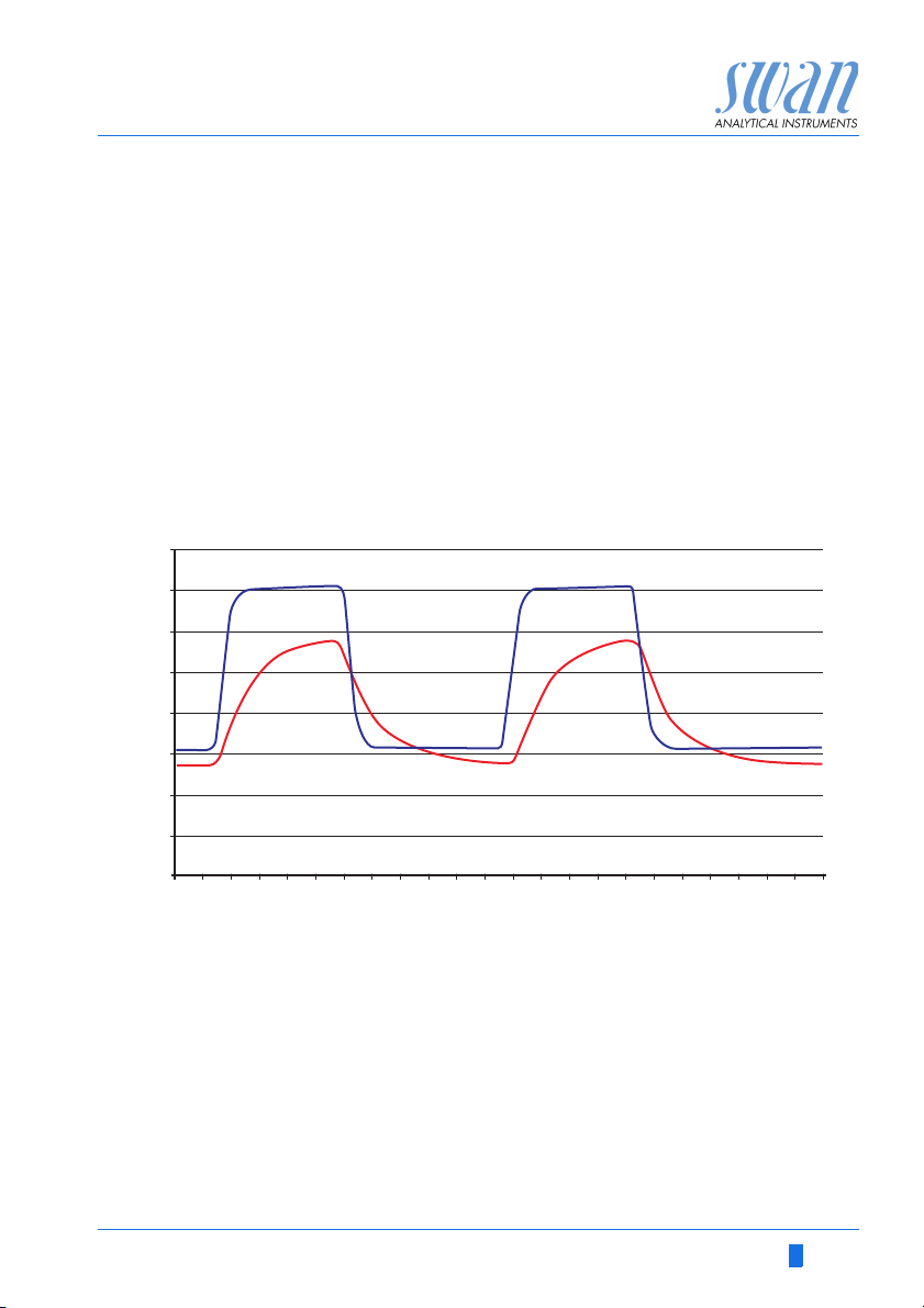
Faraday
Verification
40
35
30
25
20
15
10
Dissolved Oxygen [ppm]
5
For AMI Oxytrace QED only.
When a direct current is passed through water by means of two
electrodes, electrolysis of the liquid takes place, according to the
laws of Michael Faraday. Water is converted to molecular oxygen
and hydrogen.
Thus, by controlling the current, a fixed, known amount of oxygen,
which is independent of temperature and pressure, may be generated. If the sample flow is known, an exact oxygen concentration
increment can be generated at low levels. This increment is used to
verify the flawless operation of the whole system. Thereby the response characteristics (incremental change and response time) of
the sensor are taken into account. Sensor failures (loss of electrolyte etc.) can be detected very easily as shown in the plot below.
operational sensor
defective sensor
0
30
60 90 120 150 180 210 240 270 300 330
Time [Sec]
Unusual sensor performance is recognized immediately and gives
also a maintenance indication to the operator/user. The faraday
verification is therefore an excellent QA/QC tool.
A-96.250.531 / 300617 9
Page 12

AMI Oxytrace QED
Product Description
Signal
Outputs
Relay Two potential-free contacts programmable as limit switches for
Alarm Relay One potential free contact.
Input For potential-free contact to freeze the measuring value or to inter-
Safety
Features
Two signal outputs programmable for measured values (freely
scaleable, linear or bilinear) or as continuous control output (control
parameters programmable).
Current loop: 0/4–20 mA
Maximal burden: 510
Third signal output available as an option.
measuring values, controllers or timer for system cleaning with automatic hold function. Both contacts can be used as normally open
or normally closed.
Maximum load: 1 A/250 VAC
Alternatively:
Open during normal operation, closed on error and loss of
power.
Closed during normal operation, open on error and loss of
power.
Summary alarm indication for programmable alarm values and instrument faults.
rupt control in automated installations (hold function or remote-off)
No data loss after power failure. All data is saved in non-volatile
memory. Over voltage protection of in- and outputs.Galvanic separation of measuring inputs and signal outputs.The analyzer is factory tested and ready for installation and operation.
Communica-
tion Interface
(optional)
USB Interface for logger download
RS485 with Fieldbus protocol Modbus or Profibus DP.
HART interface
10 A-96.250.531 / 300617
Page 13
AMI Oxytrace QED
A
B
C
D
E
F
G
Product Description
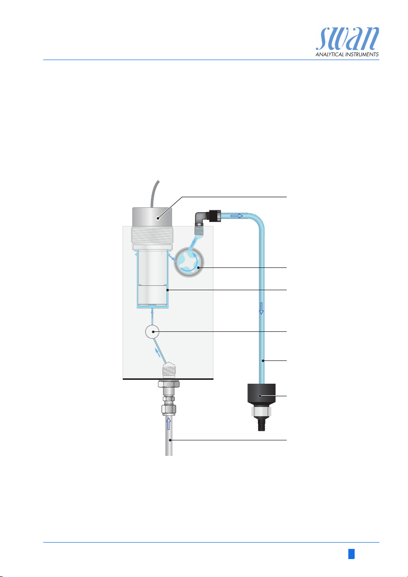
Fluidics AMI Oxytrace
Swansensor oxygen combined with QV-flow PMMA OTG flow cell.
The sample flows via sample inlet [G] through the flow regulating
valve [D], where the flow rate can be adjusted. Then the sample
flows into the measuring cell [C] were the Oxygen concentration
and temperature of the sample is measured.
The sample leaves the measuring cell via flow sensor [B] through
the sample outlet [E] and the drain funnel [F].
A
Oxygen sensor
B
Flow sensor
C
Flow cell
D
Flow regulating valve
A-96.250.531 / 300617 11
E
Sample outlet
F
Drain funnel
G
Sample inlet
Page 14
AMI Oxytrace QED
A
B
C
D
F
E
G
H
Product Description
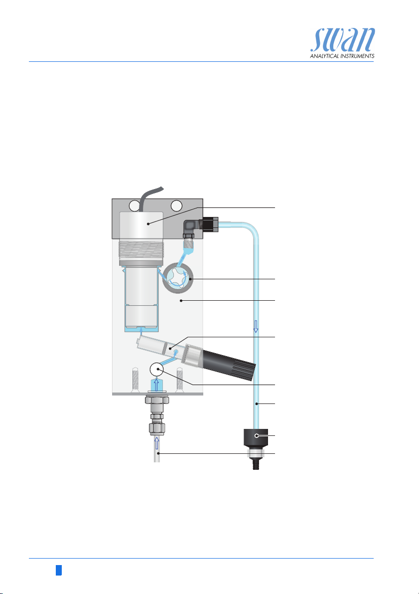
Fluidics AMI Oxytrace QED
Swansensor oxygen combined with QV-flow PMMA OTG flow cell.
The sample flows via sample inlet [H] through the flow regulating
valve [E], where the flow rate can be adjusted. Then the sample
flows through the faraday electrode [D] into the measuring cell [C]
were the Oxygen concentration of the sample is measured.
The sample leaves the measuring cell via flow sensor [B] through
the sample outlet [F] and the drain funnel [G].
A
Oxygen sensor
B
Flow sensor
C
Flow cell
D
Faraday electrode
12 A-96.250.531 / 300617
E
Flow regulating valve
F
Sample outlet
G
Drain funnel
H
Sample inlet
Page 15

AMI Oxytrace QED
Product Description
2.2. Technical Data
Power Supply Voltage:
Power consumption:
Electronics Aluminium with a protection degree of IP 66 / NEMA 4X
housing Ambient temperature:
Humidity:
Display:
Sample
requirements
Flow cell and
connection
On-Site
requirements
Accuracy
Reproducibility
Flow rate:
Temperature:
Inlet pressure:
Outlet pressure
pH:
Suspended solids:
Flow cell made of acrylic glass with built-in flow adjustment valve
and digital sample flow meter
Sample inlet:
Sample outlet:
Sample inlet:
Sample outlet:
± 1.5% of measured value or ± 0.2 ppb
±1% of measured value or ± 0.15 ppb
100–240 VAC (± 10%)
50/60 Hz (± 5%)
or 24 VDC (± 10%)
max. 30 VA
-10 to +50 °C
10–90% rel., non condensing
backlit LCD, 75 x 45 mm
8–25 l/h
15–45 °C
0.2 to 1 bar
pressure free
not lower than pH 4
less than 10 ppm
1/4” Swagelok tube adapter
for flexible tube 15x20 mm
Swagelok connection for stainless steel
tube 1/4”.
15x20 mm (1/2”) hose nozzle which
must end in a pressure free waste of sufficient capacity.
Measuring
Range
Temperature
Sample Flow
Measurement
A-96.250.531 / 300617 13
up to 60°C
Resolution: 0.1°C
With Swan sample flow meter and alarm in case of insufficient
sample flow.
Page 16

AMI Oxytrace QED
AMI Oxytrace
850 mm / 33½”
13 mm / ½”
4 x dia. 10 mm / ⅜”
254 mm/ 10”
280 mm/ 11”
824 mm / 32
7
/
16
”
Product Description
Dimensions
(Oxytrace and
Oxytrace QED)
Panel:
Mounting hole distance
Screws:
Weight:
Stainless steel
280x850x 150 mm
254x824
8 mm diameter
12.0 kg
14 A-96.250.531 / 300617
Page 17
AMI Oxytrace QED
A
B
C
D
E
F
G
H
I
Product Description
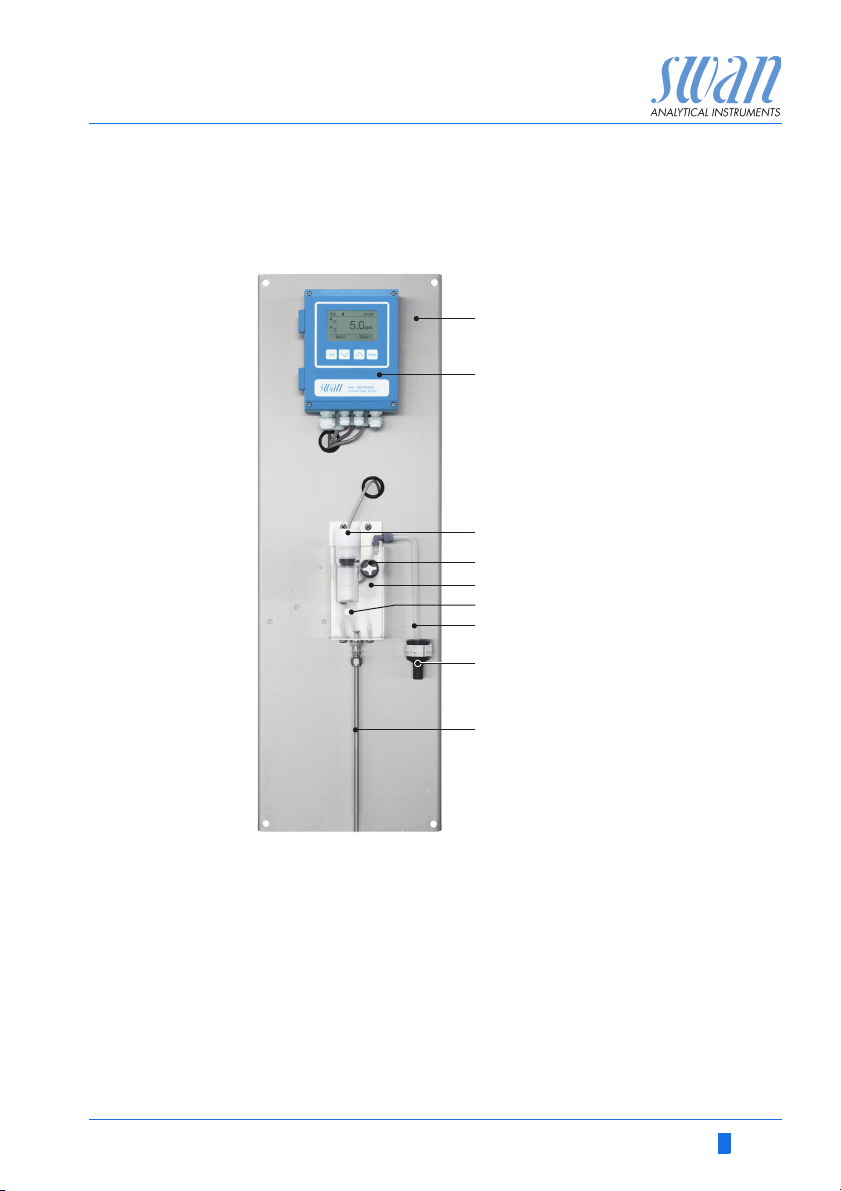
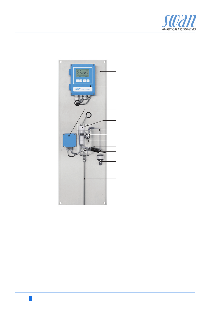
2.3. Instrument Overview
AMI Oxytrace
A
Panel
B
AMI Transmitter
C
Oxygen sensor
D
Flow sensor
E
Flow cell
A-96.250.531 / 300617 15
F
Flow regulating valve
G
Sample outlet
H
Drain funnel
I
Sample inlet
Page 18
AMI Oxytrace QED
A
B
C
D
E
F
G
H
I
J
K
Product Description
AMI Oxytrace QED
A
Panel
B
AMI Transmitter
C
Faraday control unit
D
Oxygen sensor
E
Sample outlet
F
Flow sensor
G
Flow cell
H
Flow regulating valve
I
Faraday electrode
J
Drain funnel
K
Sample inlet
16 A-96.250.531 / 300617
Page 19
AMI Oxytrace QED
Product Description
2.4. Single Components
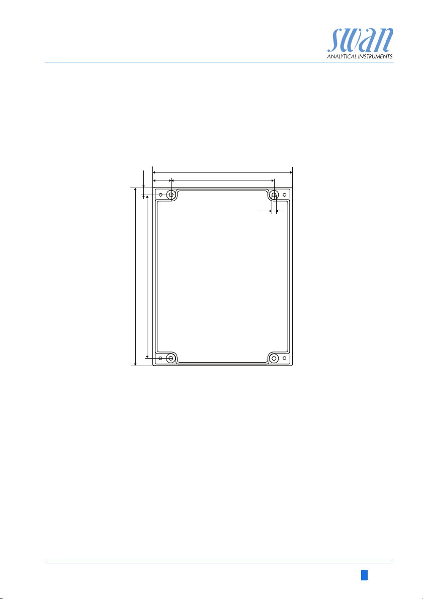
2.4.1 AMI Oxytrace Transmitter
Electronic transmitter and controller for oxygen measurement.
18.5
7.5
180
165
140
103
4.5
Dimensions Width:
Height:
Depth:
Weight:
Specifications Electronics case:
Protection degree:
Display:
Electrical connectors:
A-96.250.531 / 300617 17
140 mm
180 mm
70 mm
1.5 kg
Cast aluminum
IP 66 / NEMA 4X
backlit LCD, 75 x 45 mm
screw clamps
Page 20
AMI Oxytrace QED
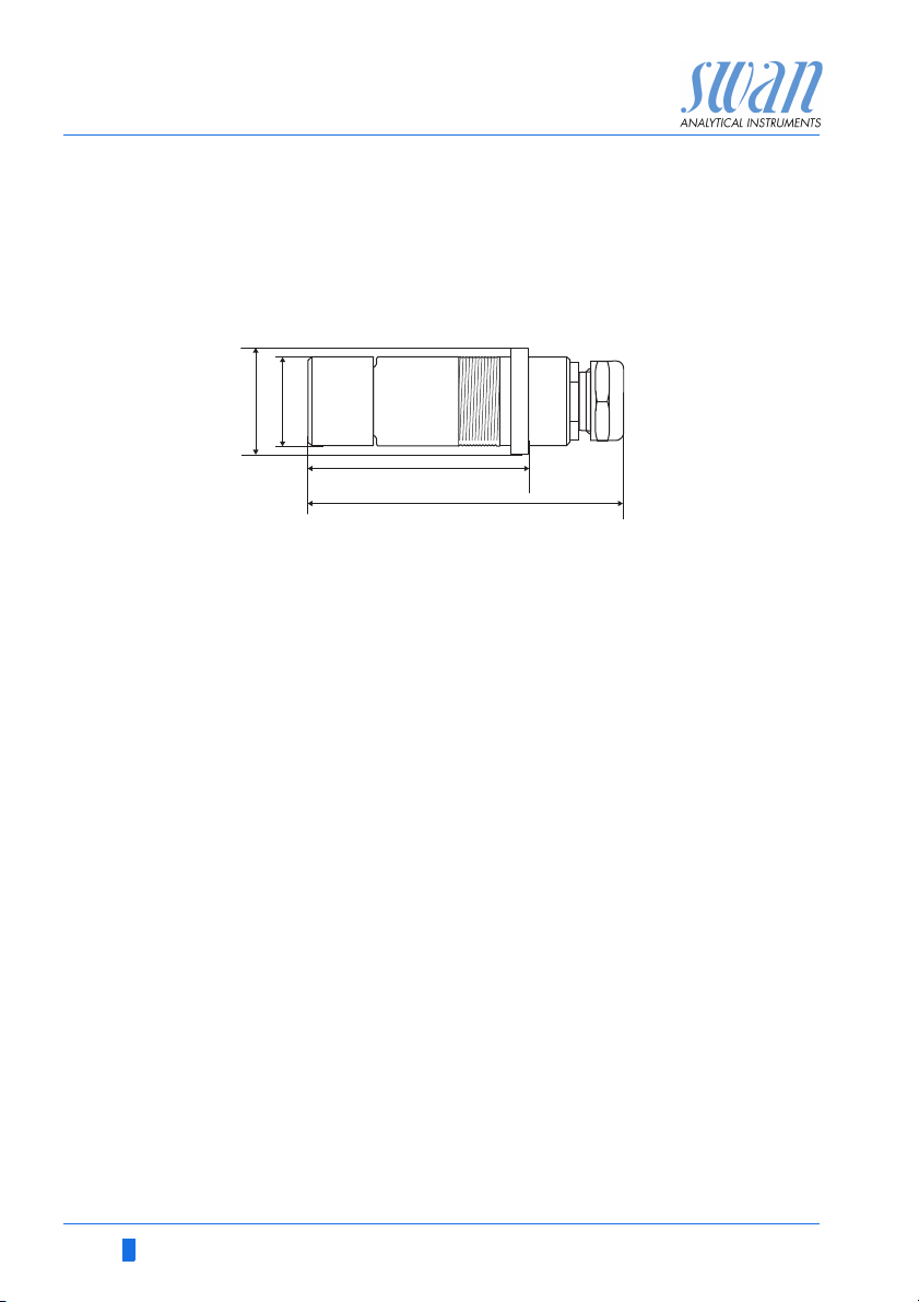
100
59
31.9
38.3
Product Description
2.4.2 Sensor OXYTRACE G
Sensor for the measurement of dissolved oxygen in ultra pure water. Precise oxygen measuring cell with integrated temperature
sensor and guard electrode for faster initial response time after
maintenance.
Technical data:Clark oxygen electrode
Cathode gold, anode silver, guard silver
Zero current-free electrode system
Robust 25 µm fluoropolymer diaphragm
Measuring
range
Temp. sensor:NT5K
Accuracy:0,3 % if calibration temperature = measuring temp.
Precision
Response time
Minimal flow
Operating temp.
Material
Protection
Weight
0–20 ppm O
Automatic range switching
:
Range
0.1–9.99 ppb
10–199.9 ppb
200– 1999 ppb
2–20 ppm
0 – 200% saturation
1,5 % at ± 10 °C deviation to cal. temperature
± 1 % of reading or ±0.15 ppb
:
< 30 seconds (rising concentration)
t
:
90
50 cm/s Pressure resistance: 3 bar
:
max. 50 °C
:
shaft: polyacetal copolymer
:
cathode/anode/guard: gold/silver/silver
membrane: fluoropolymer
IP 68
:
150 g
:
(25 °C)
2
Resolution
0.01 ppb
0.1 ppb
1.0 ppb
0.01 ppm
18 A-96.250.531 / 300617
Page 21
AMI Oxytrace QED
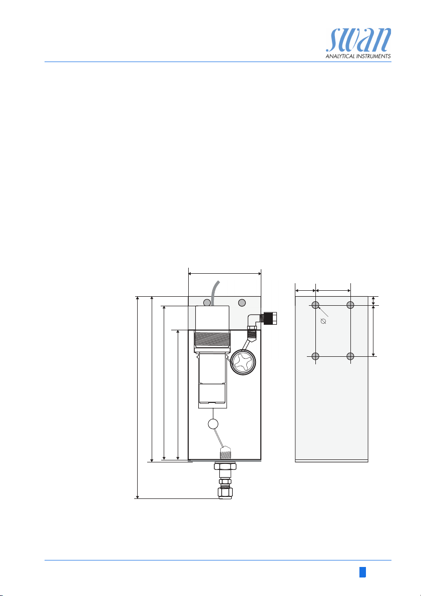
217.7
178.5
164
138
80
21
38
8
62
5.3
Product Description
2.4.3 QV-Flow PMMA OTG
Flow cell Flow cell made of acrylic glass with integrated flow sensor.
Sample temp. max. 45 °C
Inlet pressure max. 1 bar
Outlet pressure
Sample flow 6–25 l/h
Process con-
nection inlet
Outlet SERTO angle for 6 mm flexible tube
Dimensions see picture below
Pressure free
Swagelok connection for 1/4” tube
A-96.250.531 / 300617 19
Page 22

AMI Oxytrace QED
Product Description
2.4.4 B-Flow SS316L OTG
Flow cell B-Flow SS316L OTG is made of stainless steel without flow sensor
and can be used for higher operating pressures and temperatures.
Operating temp.
Sensor max. 50 °C
Operating
pressure
Sensor max. 3 bar
Flow cell
connection
Dimensions see picture below
-10 to + 130 °C
max. 5 bar at 130 °C
2x female thread 1/8" ISO
52
40
126.1
128.6
99.5
20 A-96.250.531 / 300617
Page 23

AMI Oxytrace QED
Installation
3. Installation
The first part of this chapter describes the preparing and placing of
the system in position for use. The second part describes the wiring
and the properties of the signal outputs and relay.
Restrictions
on use
3.1. Installation Check List
If exposed to weather, install a cover to protect the instrument from
insolation and precipitation. See Technical Data, p. 13 for temperature limitations.
Check Instrument’s specification must conform to the National Electrical
On site
requirements
Installation Mount the instrument in vertical position. Display should be at eye
Electrical
Connections
Swansensor
Oxytrace G
Code, all state and local codes, and all plant codes and standards
for electrical equipment.
100–240 VAC ( 10%), 50/60 Hz ( 5%) or 24 VDC (±10%),
isolated power outlet with ground connection and 30 VA
Sample line with 8– 25 l/h and 0.2 – 3 bar.
Waste line with pressure free drain.
level.
Connect the sample and waste line, see Connecting Sample Inlet
and Outlet, p. 23.
Connect all external devices like limit switches, current loops and
pumps, see Electrical Connections, p. 25.
Connect the power cord, do not switch on power until all external
devices are connected.
The Swansensor Oxytrace G is delivered with prefilled electrolyte
chamber. A transport protection cap filled with water keeps the
sensor wet during transport and storage. Before installation,
remove the transport protection cap and clean the sensor surfaces with water. Afterwards install the oxygen sensor and connect the cable.
See Install the Swansensor Oxytrace G, p. 24.
A-96.250.531 / 300617 21
Page 24

AMI Oxytrace QED
Installation
Tur n-o n
power
Run-in Period
Calibration
Open
Sample Flow
Programming Program all parameters for external devices (interface, etc.). Set
Switch on power.
First, the analyzer performs a self test, displays the firmware version and then starts normal operation
Leave the sensor at the air. The sensor has to run-in for at least
30 min, better 1 h. During this time it has to be at air with a dry and
clean membrane and has to be connected to the powered instrumenty. Calibrate the sensor after this time, see Calibration, p. 47.
and mount it into the flow cell afterwards.
Open the flow regulating valve to allow sample flow into the flow
cell and into the waste. Sample must always overflow into waste
all parameters for instrument operation (limits, alarms).
3.2. Mounting of Instrument Panel
The first part of this chapter describes the preparing and placing of
the system for use.
The instrument must only be installed by trained personnel.
Mount the instrument in vertical position.
For ease of operation mount it so that the display is at eye
level.
For the installation a kit containing the following installation
material is available:
– 4 Screws 8x60 mm
– 4 Dowels
– 4 Washers 8.4/24 mm
Mounting re-
quirements
The instrument is only intended for indoor installation.
For dimensions see Dimensions (Oxytrace and Oxytrace QED), p.
14.
22 A-96.250.531 / 300617
Page 25
AMI Oxytrace QED
12
3
9
6
ABCDE
F
Installation
3.3. Connecting Sample Inlet and Outlet
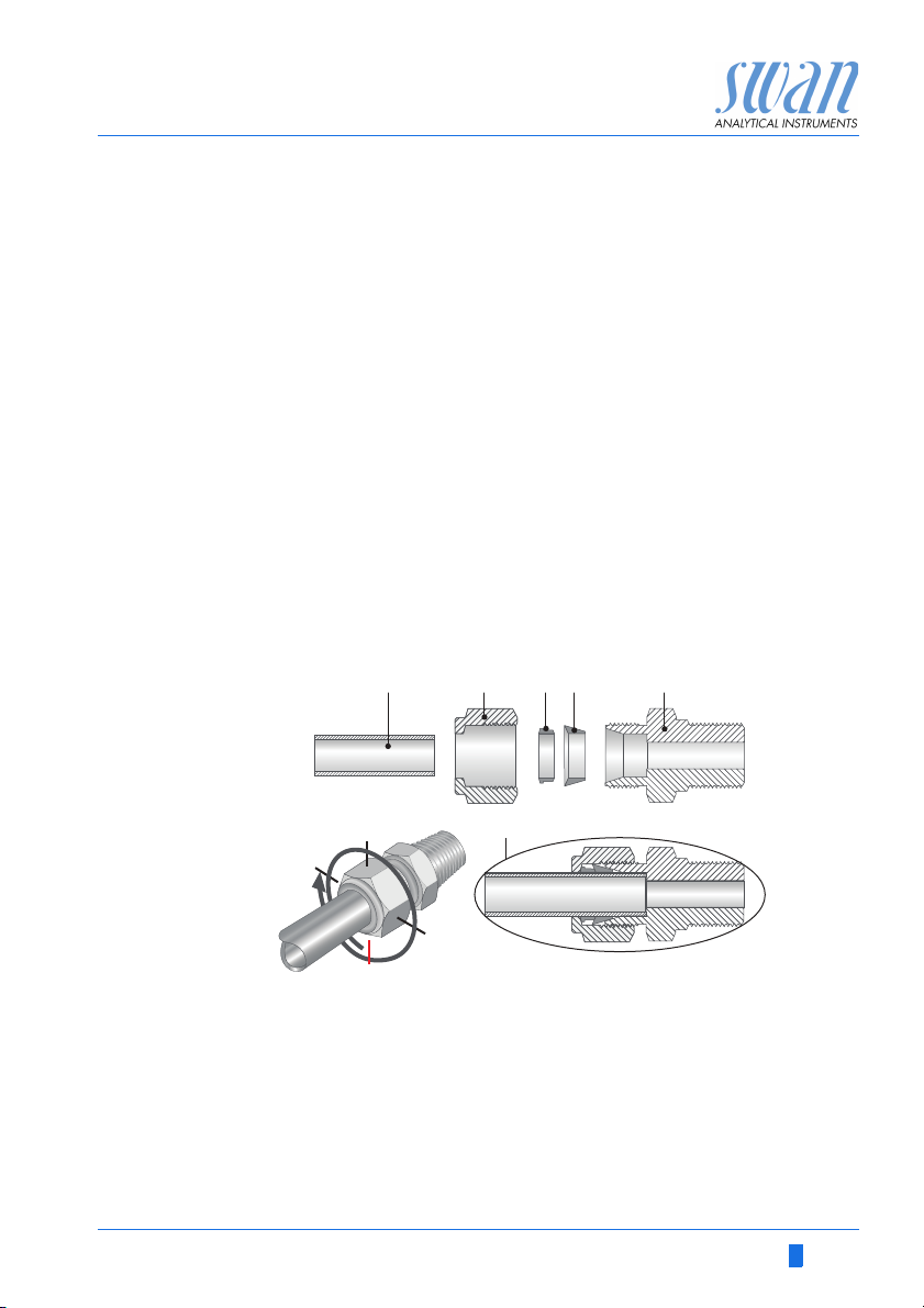
3.3.1 Swagelok Fitting Stainless Steel at Sample Inlet
Preparation Cut the tube to length and deburr it. The tube must be straight and
free from blemishes for approximately 1,5 x tube diameter from the
end.
Lubrication with lubricating oil, MoS2, Teflon etc. is recommended
for the assembly and reassembly of bigger sized unions (thread,
compression cone).
Installation 1 Insert the compression ferrule [C] and the compression
cone [D] into the union nut [B].
2 Screw on the union nut onto the body, do not tighten it.
3 Push the stainless steel pipe through the union nut as far as it
reaches the stop of the body.
4 Mark the union nut at 6 o’clock position.
5 While holding the fitting body steady, tighten the nut union 1¼
rotation using an open ended spanner.
A
Stainless steel tube
B
Union nut
C
Compression ferrule
D
Compression cone
E
Body
F
Tightened connection
A-96.250.531 / 300617 23
Page 26
AMI Oxytrace QED
A
B
C
A
B
C
D
E
Installation
3.3.2 FEP Tube at Sample Outlet
1/2” Tube at waste funnel.
Connect the 1/2” tube [C] to the hose nozzle [B] and place it into a
drain with atmospheric pressure.
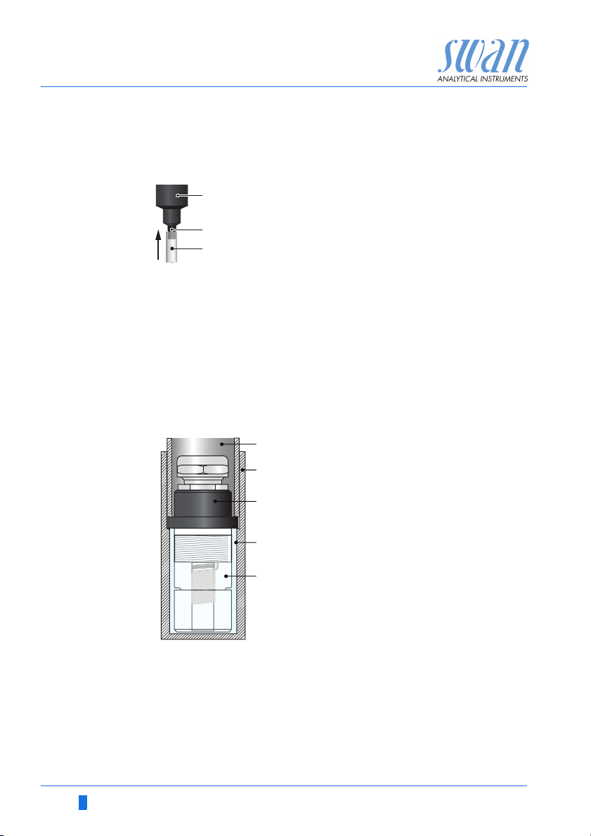
3.4 Install the Swansensor Oxytrace G
The Swansensor Oxytrace G is delivered with prefilled electrolyte
chamber [E]. A transport protection cap [B] filled with water [D]
keeps the sensor wet during transport and storage. To install the
sensor proceed as follows:
A
Waste funnel
B
Hose nozzle
C
1/2” tube
A
Fixing sleeve
B
Transport protection cap
C
Swansensor Oxytrace G
D
Water
E
Sensor cap filled with electrolyte
24 A-96.250.531 / 300617
1 Unscrew the fixing sleeve [A].
2 Remove the transport protection cap [B].
3 Clean the Swansensor Oxytrace G [C] with water.
4 Install the Swansensor Oxytrace G into the flow cell
5 Connect the sensor cable to the transmitter, see Electrical Con-
nection Diagram AMI Oxytrace, p. 27.
Page 27

AMI Oxytrace QED
Installation
3.5. Electrical Connections
WARNING
Risk of electrical shock.
Do not perform any work on electrical components if the transmitter is switched on. Failure to follow safety instructions could
result in serious injury or death.
Always turn off AC power before manipulating electric parts.
Grounding requirements: Only operate the instrument from
an power outlet which has a ground connection.
Make sure the power specification of the instrument corre-
sponds to the power on site.
Cable
thicknesses
In order to comply with IP66, use the following cable thicknesses
ABC
PG 11 cable gland: cable Ø
A
B
PG 7 cable gland: cable Ø
C
PG 9 cable gland: cable Ø
outer
3–6.5 mm
outer
4–8 mm
outer
5–10 mm
NOTICE: Protect unused cable glands
Wire For Relays: Use max. 1.5 mm
end sleeves.
For Signal Outputs and Input: Use 0.25 mm
2
/ AWG 14 stranded wire with
2
/ AWG 23
stranded wire with end sleeves.
A-96.250.531 / 300617 25
Page 28
AMI Oxytrace QED
Installation
WARNING
External Voltage.
External supplied devices connected to relay 1 or 2 or to the
alarm relay can cause electrical shocks
Make sure that the devices connected to the following con-
tacts are disconnected from the power before resuming in-
stallation.
–relay 1
–relay 2
– alarm relay
WARNING
To prevent from electrical shock, do not connect the instrument
to the power unless the ground wire (PE) is connected.
Do not connect unless specifically instructed to do so.
WARNING
The mains of the AMI Transmitter must be secured by a main
switch and appropriate fuse or circuit breaker.
26 A-96.250.531 / 300617
Page 29
AMI Oxytrace QED
Installation
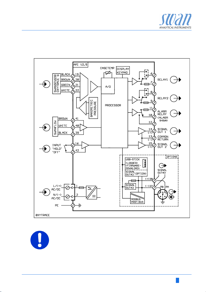
3.5.1 Electrical Connection Diagram AMI Oxytrace
CAUTION
Use only the terminals shown in this diagram, and only for the
mentioned purpose. Use of any other terminals will cause short
circuits with possible corresponding consequences to material
and personnel.
A-96.250.531 / 300617 27
Page 30
AMI Oxytrace QED
Installation
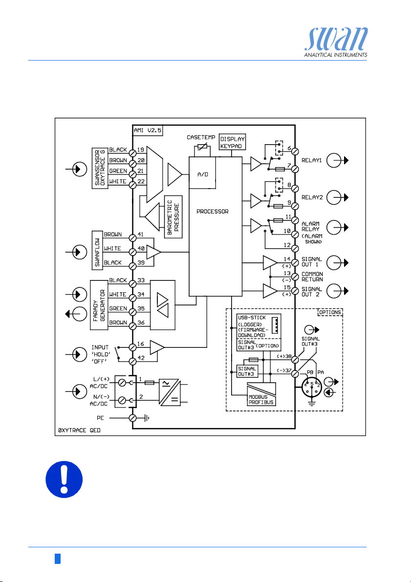
3.5.2 Electrical Connection Diagram AMI Oxytrace QED
CAUTION
Use only the terminals shown in this diagram, and only for the
mentioned purpose. Use of any other terminals will cause short
circuits with possible corresponding consequences to material
and personnel.
28 A-96.250.531 / 300617
Page 31

AMI Oxytrace QED
A
B
C
D
Installation
3.5.3 Power Supply
WARNING
Risk of electrical shock
Do not perform any work on electrical components if the transmitter is switched on. Failure to follow safety instructions could
result in serious injury or death.
Always turn off AC power before manipulating electric parts.
Installation and maintenance of electrical parts must be per-
formed by professionals.
A
Power supply connector
B
Neutral conductor, Terminal 2
C
Phase conductor, Terminal 1
D
Protective earth PE
NOTICE: The protective earth wire (Ground) has to be
connected to the grounding terminal.
Installation
requirements
A-96.250.531 / 300617 29
The installation must meet the following requirements.
Mains fuse 1.6 AT
Mains cable to comply with standards IEC 60227 or IEC
60245; flammable rating FV1
Mains equipped with an external switch or circuit-breaker
– near the instrument
– easily accessible to the operator
– marked as interrupter for AMI Oxytrace QED
Page 32

AMI Oxytrace QED
10
12
11
0V
1)
10
12
11
0V
Installation
3.6. Input
NOTICE: Use only potential-free (dry) contacts.
The total resistance (sum of cable resistance and resistance of
the relay contact) must be less than 50 Ω.
Terminals 16 and 42
If the signal output is set to hold, the measurement is interrupted if
input is active.
For programming see Menu Installation 5.3.4, p. 85.
3.7. Relay Contacts
3.7.1 Alarm Relay
NOTICE: Max. load 1 A/250 VAC
Alarm output for system errors.
Error codes see Error List, p. 59.
NOTICE: With certain alarms and certain settings of the AMI
transmitter the alarm relay does not switch. The error, however,
is shown on the display.
Ter min als Description Relay connection
1)
NC
Normally
Closed
NO
Normally
Open
10/11 Active (opened) during normal
operation.
Inactive (closed) on error and
loss of power.
12/11 Active (closed) during normal
operation.
Inactive (opened) on error and
loss of power.
1) usual use
30 A-96.250.531 / 300617
Page 33

AMI Oxytrace QED
6
0V
7
A
B
Installation
3.7.2 Relay 1 and 2
NOTICE: Max. load 1 A/250 VAC
Relay 1 and 2 can be configured as normally open or as normally
closed. Standard for both relays is normally open. To configure a
Relay as normally closed, set the jumper in the upper position.
NOTICE: Some error codes and the instrument status may
influence the status of the relays described below.
Relay
config. Terminals
Normally
Open
Normally
Closed
6/7: Relay 1
8/9: Relay 2
6/7: Relay 1
8/9: Relay 2
Jumper
pos. Description Relay configuration
Inactive (opened) during
normal operation and
loss of power.
Active (closed) when a
programmed function is
executed.
Inactive (closed) during
normal operation and
loss of power.
Active (opened) when a
0V
programmed function is
executed.
6
7
ABJumper set as normally open (standard setting)
Jumper set as normally closed
For programming see Menu Installation 5.3.2 and 5.3.3, p. 81.
A-96.250.531 / 300617 31
Page 34

AMI Oxytrace QED
A
BC
DE
Installation
CAUTION
Risk of damage of the relays in the AMI Transmitter due to
heavy inductive load.
Heavy inductive or directly controlled loads (solenoid valves,
dosing pumps) may destroy the relay contacts.
To switch inductive loads > 0.1 A use an AMI relay box avail-
able as an option or suitable external power relays.
Inductive load Small inductive loads (max 0.1A) as for example the coil of a power
Resistive load Resistive loads (max. 1A) and control signals for PLC, impulse
Actuators Actuators, like motor valves, are using both relays: One relay con-
relay can be switched directly. To avoid noise voltage in the
AMI Transmitter it is mandatory to connect a snubber circuit in parallel to the load.
A snubber circuit is not necessary if an AMI relaybox is used.
A
AC or DC power supply
B
AMI Transmitter
C
External power relay
D
Snubber
E
Power relay coil
pumps and so on can be connected without further measures
A
AB
C
tact is used for opening, the other for closing the valve, i.e. with the
2 relay contacts available, only one motor valve can be controlled.
Motors with loads bigger than 0.1A must be controlled via external
power relays or an AMI relay box.
A
BC
AMI Transmitter
B
PLC or controlled pulse pump
C
Logic
A
AC or DC power supply
B
AMI Transmitter
C
Actuator
M
32 A-96.250.531 / 300617
Page 35

AMI Oxytrace QED
Installation
3.8. Signal Outputs
3.8.1 Signal output 1 and 2 (current outputs)
NOTICE: Max. burden 510 Ω.
If signals are sent to two different receivers, use signal isolator
(loop isolator).
Signal output 1: Terminals 14 (+) and 13 (-)
Signal output 2: Terminals 15 (+) and 13 (-)
Programming see menu 5.2 Signal Outputs, p. 75
3.9. Interface Options
A
AMI Transmitter
A
B
Slot for interfaces
C
Frontend PCB
D
Screw terminals
B
C
D
The slot for interfaces can be used to expand the functionality of
the AMI instrument with either:
an additional signal output
a Profbus or Modbus connection
a HART connection
an USB Interface
A-96.250.531 / 300617 33
Page 36

AMI Oxytrace QED
Installation
3.9.1 Signal Output 3
Terminal 38 (+) and 37 (-).
Requires the additional board for the third signal output 0/4– 20 mA
PCB. The third signal output can be operated as a current source
or as a current sink (switchable via switch [A]). For detailed information see the corresponding installation instruction.
NOTICE: Max. burden 510
Third signal output 0/4 - 20 mA PCB
A Operating mode selector switch
3.9.2 Profibus, Modbus Interface
Terminal 37 PB, Terminal 38 PA
To connect several instruments by means of a network or to config-
ure a PROFIBUS DP connection, consult the PROFIBUS manual.
Use appropriate network cable.
NOTICE: The switch must be ON, if only one instrument is
installed, or on the last instrument in the bus.
.
A
OFF
ON
A
Profibus, Modbus Interface PCB (RS 485)
A On - OFF switch
34 A-96.250.531 / 300617
Page 37

AMI Oxytrace QED
Installation
3.9.3 HART Interface
Terminals 38 (+) and 37 (-).
The HART interface PCB allows for communication via the HART
protocol. For detailed information, consult the HART manual.
HART Interface PCB
3.9.4 USB Interface
The USB Interface is used to store Logger data and for Firmware
up load. For detailed information see the corresponding installation
instruction.
A
B
USB Interface
A-96.250.531 / 300617 35
Page 38

AMI Oxytrace QED
A
Instrument Setup
4. Instrument Setup
4.1. Establish Sample Flow
1 Open the flow regulating valve [A] and wait until the flow cell is
completely filled.
2 Switch on power.
3 Adjust the sample flow to 8–25 l/h.
4.2. Programming
Program all parameters for external devices (interface, recorders,
etc.)
Program all parameters for instrument operation (limits, alarms),
see Program List and Explanations, S. 69
36 A-96.250.531 / 300617
Page 39

AMI Oxytrace QED
Exit Enter
BCDA
25.4°C
RUN
9 l/h
14:10:45
R1
1.05 ppb
R2
1
Installation
Operation
Diagnostics
Messages
Maintenance
Main Menu
Enter
Exit
Operation
5. Operation
5.1. Keys
A to exit a menu or command (rejecting any changes)
to move back to the previous menu level
B to move DOWN in a menu list and to decrease digits
C to move UP in a menu list and to increase digits
D to open a selected sub-menu
to accept an entry
Program
Access, Exit
A-96.250.531 / 300617 37
Page 40

AMI Oxytrace QED
Operation
5.2. Display
AB CD
RUN
R1
0.15
R2
H
12 l/h
15:20:18
ppm
23 °C
E
F
G
A RUN normal operation
HOLD input closed or cal delay: Instrument on hold (shows
OFF input closed: control/limit is interrupted (shows status
B ERROR Error Fatal Error
C Keys locked, transmitter control via Profibus
D Time
E Process values
F Sample Temperature
G Sample flow in i/h
H Relay status
status of signal outputs).
of signal outputs).
Relay status, symbols
upper/lower limit not yet reached
upper/lower limit reached
control upw./downw. no action
control upw./downw. active, dark bar indicates control intensity
motor valve closed
motor valve: open, dark bar indicates approx. position
timer
timer: timing active (hand rotating)
38 A-96.250.531 / 300617
Page 41

AMI Oxytrace QED
1
Messages
Operation
Maintenance
Diagnostics
Main Menu
Installation
1.1
Pending Errors
Messages
Maintenance List
Message List
2.1
Interface
I/O State
Sample
Identification
Sensors
Diagnostics
3.1
Calibration
Maintenance
Set Time 23.09.06 16:30:00
Simulation
Service
4.1
Logger
Relay Contacts
Sensors
Operation
5.1
Interface
Miscellaneous
Relay Contacts
Sensors
Signal Outputs
Installation
Operation
5.3. Software Structure
Menu Messages 1
Reveals pending errors as well as an event history
(time and state of events that have occurred at an
earlier point of time).
It contains user relevant data.
Menu Diagnostics 2
Provides user relevant instrument and sample data.
A-96.250.531 / 300617 39
Menu Maintenance 3
For instrument calibration, relay and signal output
simulation, and to set the instrument time.
It is used by the service personnel.
Menu Operation 4
User relevant parameters that might need to be
modified during daily routine. Normally password
protected and used by the process-operator.
Subset of menu 5 - Installation, but process-related.
Menu Installation 5
For initial instrument set up by SWAN authorized
person, to set all instrument parameters. Can be
protected by means of password.
Page 42

AMI Oxytrace QED
5.1.2
Sensors
Sensor type FOME
Temperature NT5K
Standards
Disinf. Free chlorine
4.4.1
Logger
Log interval 30 min
Clear logger no
4.1.3
Logger
Clear logger no
Log interval 30min
1 Hour
Interval.
5 min
30 min
10 min
4.1.3
Logger
Log interval 10 min
Clear logger no
4.1.3
Logger
Log interval
Clear logger no
No
Save ?
Yes
5.3.1.1.1
Alarm High 10.00 ppm
Alarm oxygen
Alarm Low 1.00 ppb
Hysteresis 0.10 ppb
Delay 5 Sec
5.3.1.1.1
Alarm oxygen
Alarm Low 1.00 ppb
Hysteresis 0.10 pp
Delay 5 Sec
Alarm High 8.00 ppb
Operation
5.4. Changing Parameters and values
Changing
parameters
The following example shows how to change the logger interval:
1 Select the parameter you want to
change.
2 Press [Enter]
3 Press [ ] or [ ] key to
highlight the required parameter.
4 Press [Enter] to confirm the selec-
tion or [Exit] to keep the previous
parameter).
The selected parameter is
highlighted (but not saved yet).
5 Press [Exit].
Yes is highlighted.
6 Press [Enter] to save the new pa-
rameter.
The system reboots, the new
parameter is set.
Changing
values
1 Select the value you want to
change.
2 Press [Enter].
3 Set required value with [ ] or
[] key.
4 Press [Enter] to confirm the new
value.
5 Press [Exit].
Yes is highlighted.
40 A-96.250.531 / 300617
6 Press [Enter] to save the new val-
ue.
Page 43

AMI Oxytrace QED
Maintenance
6. Maintenance
Maintenance frequency depends strongly on the water quality. The
AMI Oxytrace QED is designed for determination of low level of dissolved oxygen in high purity water.
It is not suitable for the measurement of dissolved oxygen in waste
water.
6.1. Maintenance Table
Weekly Check sample flow.
Monthly If necessary, perform an air calibration.
Half-yearly Clean Oxytrace G membrane with a soft tissue,
Yearly If necessary, replace filling electrolyte.
Every 2nd
year
see Maintenance of the Oxygen Sensor, p. 42.
Clean faraday electrode, see Maintenance of the
Faraday electrode, p. 45
If the sensor is exposed to air
frequently and during long time intervals, the
electrolyte and membrane may have to be
changed earlier (see below*).
Clean flow cell and flow meter, if dirty.
Replace Swansensor Oxytrace G membrane by
using a new, pre filled sensor cap.
*A change of membrane and electrolyte is recommended:
if indicated in the maintenance list (remaining amount <10%)
if the response of the sensor is slow
if the sensor can not be calibrated any more and/or the instru-
ment shows a corresponding error message
if the sensor signal is very unstable.
6.2. Stop of Operation for Maintenance
1 Shut off power of the instrument.
2 Stop sample flow by closing the flow regulating valve.
A-96.250.531 / 300617 41
Page 44

AMI Oxytrace QED
A
C
B
Maintenance
6.3. Maintenance of the Oxygen Sensor
WARNING
Etching liquid
The electrolyte is alkaline and caustic. It contains less than 1%
of potassium hydroxide.
Do not ingest. Wear protective goggles and gloves during
handling. Avoid contact with clothes.
In case of accidental contact with the eyes, wash immediately
with clear water and contact a physician. Show him the label
of the bottle or this section of the manual.
Short contact with skin is harmless, nevertheless wash with
lots of water.
6.3.1 Electrolyte exchange
An electrolyte exchange is indicated in the maintenance list as
soon as the remaining amount is below 10%.
A
Fixing sleeve
B
Sensor
C
Flow cell
1 Unscrew the fixing sleeve [A].
2 Remove the sensor from the flow
cell.
NOTICE: Do not pull out the sensor
with force!
To remove the sensor from the flow
cell, open the flow regulating valve
during removing the sensor. This
prevents the formation of a vacuum,
and the sensor can easily be
removed from the flow cell.
42 A-96.250.531 / 300617
Page 45

AMI Oxytrace QED
Maintenance
3 Unscrew and remove the sensor cap [H] from the Swansensor
Oxytrace G [A].
4 Empty the remaining electrolyte.
5 Refill the sensor cap with fresh electrolyte.
A
Swansensor Oxytrace G
B
Thread
C
Groove
D
A
B
C
D
E
F
G
H
Guard electrode
E
Anode
F
Measuring head
G
Cathode
H
Sensor cap with membrane
NOTICE: There is a groove [C] in the thread [B] of the sensor,
where excessive air and electrolyte can escape while screwing
the sensor cap onto the sensor. Hold the sensor in vertical
position, measuring head pointing downwards.
6 Slowly screw the sensor cap onto the sensor to allow the ex-
cess electrolyte to escape without building up too much pressure inside the electrode. Fasten sensor cap tightly.
7 Clean the sensor thoroughly and dry the sensing membrane
with a soft tissue.
8 Switch on power.
9 Let the sensor run-in at air for at least 30 min, better 1 h.
10 Afterwards perform an air calibration.
11 Install the sensor into the flow cell.
12 Select “New Filling” to reset the counter for remaining electro-
lyte, see <Maintenance>/<Service> 3.2.1, p. 71).
A-96.250.531 / 300617 43
Page 46

AMI Oxytrace QED
Maintenance
6.3.2 Clean Swansensor Oxytrace G and Flow Cell
Depending on the water quality, the Swansensor Oxytrace G and
the flow cell will necessitate a cleaning.
Before cleaning, stop operation as described in Stop of Operation
for Maintenance, p. 41.
1 Dismount the Swansensor Oxytrace G, see Electrolyte ex-
change, p. 42.
2 Clean the sensor with a soft tissue and rinse it with water after-
wards.
3 Use a soft brush to remove the dirt which sticks on the walls of
the flow cell.
4 Flush the flow cell with clean water.
5 Install the Swansensor Oxytrace G and start sample flow.
44 A-96.250.531 / 300617
Page 47

AMI Oxytrace QED
A
C
D
E
F
G
B
Maintenance
6.4. Maintenance of the Faraday electrode
A
Fixing sleeve
B
Electrode body
C
Washer
D
O-ring
E
Inner electrode
F
O-ring
G
Hollow electrode
1 Switch off the instrument and close the flow regulating valve.
A-96.250.531 / 300617 45
2 Open the faraday control unit.
3 Disconnect and remove the cable from the faraday control unit.
4 Unscrew and remove the fixing sleeve (A).
5 Remove the faraday electrode from the flow cell, do not pull on
the cable.
6 Remove the washer (C) and the o-ring [D] from the electrode
body (B).
7 Unscrew the electrode tip containing the hollow electrode (G).
Page 48

AMI Oxytrace QED
Maintenance
8 Clean the inner electrode (E) with a tissue and the hollow elec-
trode with a pipe cleaner.
The electrode surfaces should be shining metallic after
cleaning. Use a polishing detergent or a small amount of
toothpaste.
9 Rinse all parts well with water.
10 Replace the O-ring and the washer if necessary.
11 Screw the hollow electrode finger-tight onto the electrode body.
12 Insert the faraday electrode into flow cell.
13 Tighten fixing sleeve firmly.
14 Feed the electrode cable through the cable gland of the faraday
control unit.
15 Connect the electrode cable to terminal 5 (green) and terminal 6
(white).
16 Switch the instrument on.
17 Open the flow regulating valve and adjust the sample flow be-
tween 8 and 25 l/h.
46 A-96.250.531 / 300617
Page 49

AMI Oxytrace QED
3.1.5
Calibration
Close regulating valve
to turn off sample flow.
<Enter> to continue
3.1.5
Calibration
Take sensor out of
flow cell and dry
membrane and sensor
<Enter> to continue
Maintenance
6.5. Calibration
The sensing part of the sensor must not be in direct contact with
water!
In the wet flow cell, the atmosphere will be saturated with water vapor. This atmosphere will produce the most accurate calibration results.
The required time for a calibration depends mainly on the difference between temperature and oxygen content in the sample and
in the air. It can take 15 – 20 minutes. This is also the case, if the
electrolyte was exchanged.
As soon as the reading is stable, the microprocessor will store the
calibration data in the memory.The end of the calibration is indicated on the display.
To perform a calibration proceed as follows:
1 Navigate to menu <Maintenance> /<Calibration>.
2 Press [Enter] to start the calibration and follow the dialog on the
display.
3 Stop the sample flow at with the
flow regulating valve.
A-96.250.531 / 300617 47
4 Unscrew and remove the thread-
ed sleeve [A], see Electrolyte ex-
change, p. 42.
5 Remove the oxygen sensor [B]
from the flow cell [C].
6 Dry the sensor membrane and the
flow cell with a soft paper tissue.
Page 50

AMI Oxytrace QED
3.1.5
Calibration
Place the electrode into
the wet flow cell at
a slightly tilted angle.
<Enter> to continue
3.1.1
Calibration
Saturation 98.7 %
Sat. Current 32
A
Progress
3.1.1
Calibration
Saturation 98.7 %
Sat. Current 32
A
Calibration Successful
Maintenance
7 Place the electrode slightly tilted
into th e flo w cel l, so t hat t he sensor
cap rests on the rim for the O-ring.
A
B
A Tilted sensor
B Flow cell
8 Press [Enter] to start the calibra-
tion measurement.
The saturation should reach
100%, the saturation current
should be about 22 A to 33 A.
If the measuring values are not
stable during the measuring
period, the calibration will be
discarded.
9 Press [Enter] to confirm the cali-
bration.
48 A-96.250.531 / 300617
Page 51

AMI Oxytrace QED
Maintenance
6.6. Zero-Verification
Swansensor Oxytrace G for the measurement of low oxygen content (< 1 ppb).
1 Calibrate the sensor according to chapter Calibration, p. 47.
2 Prepare a 5%-sodium sulfite solution with demineralized water.
3 Put the electrode into the sodium sulfite solution afterwards. As-
sure that there are no air bubbles in front of the sensor.
4 The measured value should now be < 1 ppb.
NOTICE: Depending on the state of the electrode this process
can take several hours. In case of an electrode-refill, this can
take days until the measured value is lower than 1 ppb.
A-96.250.531 / 300617 49
Page 52

AMI Oxytrace QED
3.3
Progress
Faraday Verification
<Enter> to stop
Current Value 1.62 ppb
Faraday Conc.
12.85 ppb
3.3
Progress
Faraday Verification
Done
Efficiency 91.5 %
Faraday Conc. 12.85 ppb
Maintenance
6.7. Faraday Verification
The Faraday verification works only for oxygen concentrations below 200 ppb. If automatic Faraday verification is enabled, a periodic
check of the system is performed. A manual verification can be
started for test purposes.
Automatic
Verification
Manual
Verification
Per default the instrument performs an automatic faraday verification every 3 hours. To change the settings for automatic verification
go to menu Faraday Parameter- Timer mode, see menu 4.1.3, p.
73 for details.
Possible settings are:
off
interval
daily
weekly
To start a manual verification:
1 Navigate to menu 3.2.2 <Maintenance>/<Service>/<Faraday
Verification>.
2 Press [Enter] to start the Faraday
Verification.
The verification then starts
immediately.
3 Press [Enter] to confirm the Fara-
day Verification.
Results are saved in the Verification history menu 2.2.1.5
50 A-96.250.531 / 300617
Page 53

AMI Oxytrace QED
Maintenance
6.8. Quality Assurance of the Instrument
Every SWAN on-line instrument is equipped with integrated, autonomous quality assurance functions to survey the plausibility of each
measurement.
For the AMI Oxytrace/ AMI Oxytrace QED these are:
continuous monitoring of sample flow
continuous monitoring of the temperature inside the transmit-
ter case
periodic accuracy test with ultra high precision resistors
Further a manual, menu driven inspection procedure can be carried
out using a certified reference instrument. Running at the same
sampling point as an inspection equipment, the AMI Inspector Oxygen verifies the measuring results. After enabling the quality assurance procedure by defining the quality assurance level, the
instrument reminds the user periodically to run the procedure and
results are stored in a history for review.
Quality
assurance
level
Central feature of the quality assurance function is the assignment
of the monitored process to a Quality assurance level.
There are three predefined levels plus a user level. Hereby the inspection interval, the deviation limits of temperature and measuring
result between the inspection equipment and the monitoring instrument are defined.
Level 1: Tre nd; Measurement used as an additional informa-
tion to follow the process indicating trends.
Level 2: Standard; Monitoring of several parameters of a pro-
cess (e.g. oxygen, saturation). In case of instrument failure,
other parameters can be used for process monitoring.
Level 3: Crucial; Monitoring of critical processes, value is
used for control of another part or subsystem (valve, dosing
unit, etc.).
Additional level:
Quality level 4: User; User defined inspection interval, maxi-
mal deviation of temperature and measuring result.
A-96.250.531 / 300617 51
Page 54

AMI Oxytrace QED
Maintenance
max. deviation
Quality Level
0: Off
1: Trend
2: Standard
3: Crucial
4: User
a) sample temperature must have 25°C +/- 5°C.
Procedure The standard workflow contains following procedures:
temperature [°C]
Off Off
0.5 °C 10 %
0.4 °C 5 %
0.3 °C 5 %
0 - 2°C 0 - 20%
1 Activate SWAN Quality assurance procedure
2 Pre-test
3 Connect instruments
4 Carry out comparison measurement
5 Completion of the measurement
NOTICE: The procedure should only be carried out through
qualified personnel.
Materials / Inspection equipment:
Reference instrument: AMI INSPECTOR Oxygen
Two tubes made of PA
max. deviation
a)
result [%]
min. inspection
interval
Off
annual
quarterly
monthly
annual, quarterly,
monthly
6.8.1 Activate SWAN Quality assurance procedure
Enable quality assurance procedure at each instrument by selecting the quality level in menu 5.1.4.
The corresponding submenus are then activated.
NOTICE: The activation is necessary the first time only.
52 A-96.250.531 / 300617
Page 55

AMI Oxytrace QED
Maintenance
6.8.2 Pre-test
Reference instrument: AMI INSPECTOR Oxygen
– Check certificate; reference instrument certificate not older
than one year.
– Check battery; Battery of the AMI INSPECTOR Oxygen
should be completely charged. Remaining operating time
on display minimum 20 hours.
– Sensor is in working condition.
On-line instrument: Monitor AMI Oxytrace QED
– Good order and condition; Flow cell free of particles,
Sensor surface free of deposits.
– Check message list; Review the message list in menu 1.3
and check for frequently alarms (as for example flow
alarms). If alarms occur frequently remove cause before
starting the procedure.
6.8.3 Connect the sample lines
The choice of sampling depends strongly on local conditions on
site. Possible sampling:
via sample point,
via T-fitting or
via piggyback/downstream
NOTICE:
• avoid ingress of air, use screwed fitting,
• sample as near as possible to the process monitor,
• wait approx. 10 minutes, whilst measurement is running,
until measurement value and temperature are stabilized.
Example As an example following picture shows the connection of the refer-
A-96.250.531 / 300617 53
ence instrument via T-fitting to the process monitor.
Page 56

AMI Oxytrace QED
A
B
C
D
E
F
G
Maintenance
A
Monitor AMI Oxytrace
B
AMI INSPECTOR Oxygen
C
Reference flow cell
D
On-line flow cell
1 Stop sample flow to the monitor AMI Oxytrace by closing the
appropriate valve, e.g. back pressure regulator, sample preparation or flow regulating valve at flow cell.
2 Connect sample line of the monitor AMI Oxytrace [A] with the
sample inlet of the reference instrument AMI INSPECTOR Oxygen [B]. Use the supplied tube, made of PA.
3 Connect sample outlet of the reference instrument AMI IN-
SPECTOR Oxygen to the sample outlet funnel of the monitor.
4 Switch on the AMI INSPECTOR Oxygen. Open the flow regulat-
ing valve and regulate the sample flow to 10 l/h. The actual flow
is shown on the transmitter.
54 A-96.250.531 / 300617
E
Sample outlet
F
Sample inlet
G
T-fitting
Page 57

AMI Oxytrace QED
3.5.5
Quality Assurance
- Carry out preparations
- Install Inspector
- Sample flow to 10 l/h
<Enter> to continue
3.5.5
Quality Assurance
Value O2 0.05 ppb
Value Temp. 25.00 C
Wait 10 Minutes
<Enter> to continue
3.5.3
Quality Assurance
Value O2 0.05 ppb
Value Temp. 25.00 C
<Enter> to continue
Inspector O2 0.06 ppb
Inspector Temp. 25.0 C
3.5.4
Quality Assurance
Value H2 0.05 ppb
Value Temp. 25.00 C
<Enter> to continue
Inspector 0.06 ppb
Inspector Temp. 25.0 C
3.5.5
Quality Assurance
Max. Dev. O2 0.5 %
Max. Dev. Temp. 0.4 °C
QA-Check succesful
Dev. O2 0.1 %
Dev. Temp. 0.4 °C
Maintenance
6.8.4 Carry out comparison measurement
The comparison measurement is menu driven. Start by selecting
Quality Assurance in menu 3.5 of the monitor AMI Oxytrace.
1 Navigate to menu Maintenance /Quality Assurance.
2 Press [Enter].
3 Follow the dialog on the Display.
4 Carry out pre test preparations
Connect instruments.
Regulate sample flow to 10 l/h using the appropriate valve.
5 Wait 10 minutes whilst measure-
ment is running.
Press [Enter] to continue.
6 Read the ppb value of the refer-
ence instrument and enter under
“Inspector” by using the [ ] or
[ ] keys.
7 Press [Enter] to confirm.
A-96.250.531 / 300617 55
8 Read temperature value of the ref-
erence instrument and enter under “Inspector Temp.” by using the
[ ] or [ ] keys.
9 Press [Enter] to confirm.
10 Press [Enter] to continue.
The results are saved in QA-
History regardless if successful
or not
Page 58

AMI Oxytrace QED
Maintenance
6.8.5 Completion of the measurement
1 Stop the sample flow to the AMI Oxytrace QED by closing the
appropriate valve, e.g. back pressure regulator, sample preparation or flow regulating valve at flow cell again.
2 Close flow regulating valve of the AMI Inspector.
3 Disconnect the AMI Inspector by removing the tubes and con-
nect the sample outlet of the Monitor AMI Oxytrace QED to the
sample outlet funnel again.
4 Start sample flow again and regulate sample flow.
5 Shutdown the AMI INSPECTOR Oxygen.
If the AMI Inspector is put out of operation for a longer period of
time, see Longer Stop of Operation, p. 58.
56 A-96.250.531 / 300617
Page 59

AMI Oxytrace QED
A
B
CDEF G
Maintenance
6.9. Replacing Fuses
WARNING
External Voltage.
External supplied devices connected to relay 1 or 2 or to the
alarm relay can cause electrical shocks.
Make sure that the devices connected to the following con-
tacts are disconnected from the power before continuing the
installation.
– relay 1
– relay 2
– alarm relay
When a fuse has blown, find out the cause and fix it before
replacing it with a new one.
Use tweezers or needle-nosed pliers to remove the defective fuse.
Use original fuses provided by SWAN only.
A-96.250.531 / 300617 57
A
1.6 AT/250V Instrument power supply
B
1.0 AT/250V Relay 1
C
1.0 AT/250V Relay 2
D
1.0 AT/250V Alarm relay
E
1.0 AF/125V Signal output 2
F
1.0 AF/125V Signal output 1
G
1.0 AF/125V Signal output 3
Page 60

AMI Oxytrace QED
Maintenance
6.10. Longer Stop of Operation
1 Shut off power of the instrument.
2 Stop sample flow.
3 Remove the Swansensor Oxytrace G.
4 Clean the sensor with a soft tissue and rinse it with water after-
wards.
5 Use a soft brush to remove the dirt which sticks on the walls of
the flow cell.
6 Fill the flow cell with water.
7 Install the Swansensor Oxytrace G.
58 A-96.250.531 / 300617
Page 61

AMI Oxytrace QED
25.4°C
HOLD
8 l/h
14:10:45
R1
7.04 ppm
R2
1
Installation
Operation
Diagnostics
Messages
Maintenance
Main Menu
1.1
Message List
Pending Errors
Maintenance List
Messages
1.1.5
Pending Errors
Error Code E002
Alarm low
<Enter> to Acknowledge
Error List
7. Error List
Error
Non-fatal Error. Indicates an alarm if a programmed value is exceeded.
Such Errors are marked E0xx (bold and black).
Fatal Error (blinking symbol)
Control of dosing devices is interrupted.
The indicated measured values are possibly incorrect.
Fatal Errors are divided in the following two categories:
Errors which disappear if correct measuring conditions are re-
covered (i.e. Sample Flow low).
Such Errors are marked E0xx (bold and orange)
Errors which indicate a hardware failure of the instrument.
Such Errors are marked E0xx (bold and red)
Error or fatal Error
Error not yet acknowledged.
Check Pending Errors 1.1.5 * and
take corrective action.
Press [ENTER].
A-96.250.531 / 300617 59
Navigate to menu Messages.
Press [ENTER].
Navigate to menu Pending Errors.
Press [ENTER].
Press [ENTER] to acknowledge the
Pending Errors. The Error is reset and
saved in the Message List.
* Menu numbers see
Program Overview, S. 63
Page 62

AMI Oxytrace QED
Error List
Error Description Corrective action
E001 Oxygen Alarm high
E002 Oxygen Alarm low
E003 Saturation Alarm high
E004 Saturation Alarm low
E007 Sample Temp. high
E008 Sample Temp. low
E009 Sample Flow high
E010 Sample Flow low
– check process
– check programmed value,
see 5.3.1.1.1, S. 79
– check process
– check programmed value,
see 5.3.1.1.25, S. 79
– check process
– check programmed value,
see 5.3.1.4, S. 80
– check process
– check programmed value,
see 5.3.1.4, S. 80
– check process
– check programmed value,
see 5.3.1.3.1, S. 80
– check process
– check programmed value,
see 5.3.1.3.25, S. 80
– check sample flow
– check programmed value,
see 5.3.1.2.2, S. 80
– establish sample flow
– clean instrument
– check programmed value,
see 5.3.1.2.35, S. 80
E011 Temp. shorted
E012 Temp. disconnected
– Check wiring of sensor
– Check sensor
– Check wiring of sensor
– Check sensor
60 A-96.250.531 / 300617
Page 63

AMI Oxytrace QED
Error List
Error Description Corrective action
E013 Case Temp. high
E014 Case Temp. low
E017 Control Timeout
E018 Faraday Efficiency
E019 Quality Assurance
E024 Input active
E026 IC LM75
– check case/environment temperature
– check programmed value,
see 5.3.1.5.1, S. 80
– check case/environment temperature
– check programmed value,
see 5.3.1.5.2, S. 80
– check control device or programming in
Installation, Relay contact, Relay 1/2
see 5.3.2 and 5.3.3, S. 81
– clean Faraday electrode, see
Maintenance of the Faraday electrode,
S. 45
– perform an air calibration, see
Calibration, S. 47
– perform maintenance of the oxygen
sensor, see Maintenance of the Oxygen
Sensor, S. 42
– Perform QA Procedure using a
reference instrument, e.g. AMI Inspector
– See If Fault Yes is programmed in Menu
see 5.3.4, S. 85
– call service
E028 Signal output open
E030 EEProm Frontend
E031 Calibration Recout
A-96.250.531 / 300617 61
– check wiring on signal outputs 1 and 2
– call service
– call service
Page 64

AMI Oxytrace QED
Error List
Error Description Corrective action
E032 Wrong Frontend
E033 Power-on
E034 Power-down
E065 Electrolyte depleted
– call service
– none, normal status
– none, normal status
– Refill electrolyte, see Electrolyte
exchange, S. 42
62 A-96.250.531 / 300617
Page 65

AMI Oxytrace QED
Program Overview
8. Program Overview
For explanations about each parameter of the menus see Program
List and Explanations, S. 69.
Menu 1 Messages informs about pending errors and mainte-
nance tasks and shows the error history. Password protection
possible. No settings can be modified.
Menu 2 Diagnostics is always accessible for everybody. No
password protection. No settings can be modified.
Menu 3 Maintenance is for service: Calibration, simulation of
outputs and set time/date. Please protect with password.
Menu 4 Operation is for the user, allowing to set limits, alarm
values, etc. The presetting is done in the menu Installation
(only for the System engineer). Please protect with password.
Menu 5 Installation: Defining assignment of all inputs and
outputs, measuring parameters, interface, passwords, etc.
Menu for the system engineer. Password strongly recommended.
8.1. Messages (Main Menu 1)
Pending Errors Pending Errors 1.1.5* * Menu numbers
1.1*
Maintenance List Maintenance List 1.2.5*
1.2*
Message List Number 1.3.1*
1.3* Date, Time
A-96.250.531 / 300617 63
Page 66

AMI Oxytrace QED
Program Overview
8.2. Diagnostics (Main Menu 2)
Identification Desig. AMI Oxytrace * Menu numbers
2.1* Version 6.20-06/16
Factory Test Instrument 2.1.3.1*
2.1.3* Motherboard
Front End
Operating Time Years / Days / Hours / Minutes / Seconds 2.1.4.1*
2.1.4*
Sensors Oxytrace G Current Value
2.2* 2.2.1* (Raw value tc)
Saturation
Cal. History Number 2.2.1.5.1*
2.2.1.5* Date, Time
Sat. Current
Air pressure
Miscellaneous Case Temp. 2.2.2.1*
2.2.2* Air pressure
QA History QA History 2.2.3.1*
2.2.3*
Sample Sample ID 2.3.1*
2.3* Temperature °C
Nt5K Ohm
I/O State Alarm Relay 2.4.1*
2.4* Relay 1/2 2.4.2*
Input
Signal Output 1/2
Interface Protocol 2.5.1*
2.5* USB Stick
64 A-96.250.531 / 300617
Page 67

AMI Oxytrace QED
Program Overview
8.3. Maintenance (Main Menu 3)
Calibration Calibration 3.1.5 * Menu numbers
3.1*
Service Electrolyte Last filling
3.2* 3.2.1* Remaining amount
Remaining time
New Filling 3.2.1.5*
Faraday Verification Current Value
3.2.2 Faraday Conc.
Progress
Simulation Alarm Relay 3.2.1*
3.3* Relay 1 3.2.2*
Relay 2 3.2.3*
Signal Output 1 3.2.4*
Signal Output 2 3.2.5*
Set Time (Date), (Time)
3.4*
Quality Assurance Quality Assurance 3.5.5*
3.5*
A-96.250.531 / 300617 65
Page 68

AMI Oxytrace QED
Program Overview
8.4. Operation (Main Menu 4)
Sensors Filter Time Const. 4.1.1* * Menu numbers
4.1* Hold after Cal. 4.1.2*
Faraday Parameter Mode 4.1.3.1*
4.1.3* Interval 4.1.3.20*
Delay 4.1.3.3*
Signal Outputs 4.1.3.4*
Output/Control 4.1.3.5*
Relay Contacts Alarm Relay Alarm oxygene Alarm High 4.2.1.1.1*
4.2* 4.2.1* 4.2.1.1* Alarm Low 4.2.1.1.25*
Hysteresis 4.2.1.1.35*
Delay 4.2.1.1.45*
Alarm Saturation Alarm High 4.2.1.2.1*
4.2.1.2* Alarm Low 4.2.1.2.25*
Hysteresis 4.2.1.2.35*
Delay 4.2.1.2.45*
Relay 1/ 2 Setpoint 4.2.x.100*
4.2.2* - 4.2.3* Hysteresis 4.2.x.200*
Delay 4.2.x.30*
Input Active 4.2.4.1*
4.2.4* Signal Outputs 4.2.4.2*
Output / Control 4.2.4.3*
Fault 4.2.4.4*
Delay 4.2.4.5*
Logger Log Interval 4.3.1*
4.3* Clear Logger 4.3.2*
Eject USB Stick 4.3.3*
66 A-96.250.531 / 300617
Page 69

AMI Oxytrace QED
Program Overview
8.5. Installation (Main Menu 5)
Sensors Miscellaneous Flow 5.1.1.1* * Menu numbers
5.1* 5.1.1* Offset 5.1.1.2*
Quality Assurance Level 5.1.2.1*
5.1.2*
Signal Outputs Signal Output 1 / 2 Parameter 5.2.1.1 - 5.2.2.1*
5.2* 5.2.1* - 5.2.2* Current Loop 5.2.1.2 - 5.2.2.2*
Function 5.2.1.3 - 5.2.2.3*
Scaling Range Low 5.2.x.40.10/11*
5.2.x.40 Range High 5.2.x.40.20/21*
Relay Contacts Alarm Relay Alarm oxygen Alarm High 5.3.1.1.1*
5.3* 5.3.1* 5.3.1.1* Alarm Low 5.3.1.1.25
Hysteresis 5.3.1.1.35
Delay 5.3.1.1.45
Sample Flow Flow Alarm 5.3.1.2.1
5.3.1.2* Alarm High 5.3.1.2.2*
Alarm Low 5.3.1.2.35*
Sample Temp. Alarm High 5.3.1.3.1*
5.3.1.3* Alarm Low 5.3.1.3.25*
Alarm Saturation Alarm High 5.3.1.4.1*
5.3.1.4* Alarm Low 5.3.1.4.25
Hysteresis 5.3.1.4.35
Delay 5.3.1.4.45
Case Temp. Case Temp. high 5.3.1.5.1*
5.3.1.5* Case Temp. low 5.3.1.5.2*
Relay 1 and 2 Function 5.3.2.1–5.3.3.1*
5.3.2* and 5.3.3* Parameter 5.3.2.20–5.3.3.20*
Setpoint 5.3.2.300– 5.3.3.301*
Hysteresis 5.3.2.400–5.3.3.401*
Delay 5.3.2.50–5.3.3.50*
Input Active 5.3.4.1*
5.3.4* Signal Outputs 5.3.4.2*
Output/Control 5.3.4.3*
Fault 5.3.4.4*
Delay 5.3.4.5*
A-96.250.531 / 300617 67
Page 70

AMI Oxytrace QED
Program Overview
Miscellaneous Language 5.4.1* * Menu numbers
5.4* Set defaults 5.4.2*
Load Firmware 5.4.3*
Password Messages 5.4.4.1*
5.4.4* Maintenance 5.4.4.2*
Operation 5.4.4.3*
Installation 5.4.4.4*
Sample ID 5.4.5*
Line Break Detection 5.4.6*
Interface Protocol 5.5.1* (only with RS485
5.5* Device Address 5.5.21* interface)
Baud Rate 5.5.31*
Parity 5.5.41*
68 A-96.250.531 / 300617
Page 71

AMI Oxytrace QED
Program List and Explanations
9. Program List and Explanations
1 Messages
1.1 Pending Errors
1.1.5 Provides the list of active errors with their status (active, acknowledged). If an active error is acknowledged, the alarm relay is active
again. Cleared errors are moved to the Message list.
1.2 Maintenance List
1.2.5 Provides the list of necessary maintenance. Cleared maintenance
messages are moved to the Message list.
1.3 Message List
1.3.1 Shows the error history: Error code, date / time of issue and status
(active, acknowledged, cleared). 65 errors are memorized. Then
the oldest error is cleared to save the newest error (circular buffer).
2 Diagnostics
In diagnostics mode, the values can only be viewed, not modified.
2.1 Identification
Desig.: Designation of the instrument.
Ver sion : Firmware of instrument (e.g. 6.20-06/16)
2.1.3 Factory Test: Test date of the Instrument and Motherboard.
2.1.4 Operating Time: Shows the operating time in Years, Days, Hours,
Minutes and Seconds.
2.2 Sensors
2.2.1 Oxytrace G
Current value: Shows the actual measuring value in ppb.
Raw value tc: Shows the actual temperature compensated mea-
Saturation Shows the actual saturation in %
suring value in mA.
A-96.250.531 / 300617 69
Page 72

AMI Oxytrace QED
Program List and Explanations
2.2.1.4 Cal. History
Review the diagnostic values of the last calibration of the oxygen
sensor. Max. 64 data records are memorized.
Number: Calibration counter.
Date, Time: Date and time of the calibration.
Sat. Current: Saturation current at that time of calibration.
Air pressure: Air pressure at that time of calibration.
2.2.2 Miscellaneous:
2.2.2.1 Case Temp: Shows the actual temperature in °C inside the trans-
mitter.
Air pressure: Shows the actual air pressure in hPa
2.2.3 QA History
2.3 Sample
2.3.301 Sample ID: Shows the assigned sample identification. This
2.4 I/O State
2.4.1
Review QA values (Number, Date, Time, Deviation oxygen, Deviation Temperature, Status of QA check) of the last quality assurance
procedures.
identification is defined by the user to identify the location of the
sample
Temperature: Shows temperature in °C.
(Nt5K): Shows raw value of the temperature in
Sample Flow: Shows the sample flow in l/h
(Raw value) Shows the sample flow in Hz
Shows actual status of all in- and outputs.
Alarm Relay: Active or inactive.
Relay 1 and 2: Active or inactive.
Input: Open or closed.
Signal Output 1 and 2: Actual current in mA
Signal Output 3: Actual current in mA (if option is installed)
2.5 Interface
2.5.1 Only available if optional interface is installed.
Shows the programmed communication settings.
70 A-96.250.531 / 300617
Page 73

AMI Oxytrace QED
Program List and Explanations
3 Maintenance
3.1 Calibration
3.1.1 Start a calibration and follow the instructions on the screen. Dis-
3.2 Service
3.2.1 Electrolyte
3.2.1.5 New Filling: Select “Yes” after electrolyte exchange to reset the
3.2.2 Faraday Verification
played values are saturation in % and the saturation current in mA.
The indication bar shows the progress. Detailed explanation see
Calibration, p. 47.
Last Filling: Shows the date of the last filling of electrolyte.
Remaining Amount: Remaining amount of electrolyte in %.
Remaining Time: Remaining time in days until electrolyte
exchange
recommended.
counter.
Start a manual faraday verification. Displayed values are current
value in ppb and the faraday concentration in %.
Current value: Measuring value in ppb
Faraday conc.: Oxygen concentration in % after activating the
faraday verification.
Progress: The progress bar shows the progress of the faraday
verification.
A-96.250.531 / 300617 71
Page 74

AMI Oxytrace QED
Program List and Explanations
3.3 Simulation
In this menu the following relays and signal outputs can be tested:
Alarm relay
Relay 1 and 2
Signal output 1 and 2
Signal output 3 (if option is installed)
Select a relay or signal output with the [ ] or [ ] keys,
press the [Enter]> key to confirm. Then change the value with the
[ ] or [ ] keys. After confirming the setting with the [Enter]
key, the value is simulated by the relay/signal output.
Alarm Relay: Active or inactive.
Relay 1 and 2: Active or inactive.
Input: Open or closed.
Signal Output 1 and 2: Current in mA
Signal Output 3: Current in mA (if option is installed)
At the absence of any key activities, the instrument will switch back
to normal mode after 20 min. If you quit the menu, all simulated values will be reset.
3.4 Set Time
Adjust date and time.
3.5 Quality Assurance
Performs a Quality Assurance according to your settings. Follow
the commands on the screen. Detailed explanation see Quality As-
surance of the Instrument, p. 51.
72 A-96.250.531 / 300617
Page 75

AMI Oxytrace QED
Program List and Explanations
4 Operation
4.1 Sensors
4.1.1 Filter Time Constant: Used to damp noisy signals. The higher the
4.1.2 Hold after Cal: Delay permitting the instrument to stabilize again af-
4.1.3 Faraday Parameter
4.1.3.1 Mode: Can be set to Interval, daily, weekly or off. If Mode is set to
4.1.3.20 Interval: The interval can be set between 1h and 12h
4.1.3.21 Start Time: Start time appears if Mode is set to daily, how to set the
4.1.3.22 Calendar: Calendar appears if Mode is set to weekly, how to set
4.1.3.3 Delay: during Faraday Verification plus the delay time the signal
4.1.3.4 Signal Outputs: Select operating mode of the signal output:
4.1.3.5 Output/Control: Select operating mode of the controller output:
filter time constant, the slower the system reacts to changes of the
measured value.
Range: 5–300 Sec
ter calibration. During calibration plus hold-time, the signal outputs
are frozen (held on last valid value), alarm values, limits are not active.
Range: 0–6‘000 Sec
“Off”, no further settings are available. The Faraday Verification has
to be started manually.
start time see 5.3.2.341, p. 84.
the Calendar see 5.3.2.342, p. 85.
and control outputs are held in the operating mode programmed
below.
Range: 0–6’000 Sec.
Cont.: Signal outputs continue to issue the measured value.
Hold: Signal outputs hold the last valid measured value.
Measurement is interrupted. Errors, except fatal errors,
are not issued.
Off: Signal outputs are switched off (set to 0 or 4 mA).
Errors, except fatal errors, are not issued.
Cont.: Controller continues normally.
Hold: Controller continues based on the last valid value.
Off: Controller is switched off.
A-96.250.531 / 300617 73
Page 76

AMI Oxytrace QED
Program List and Explanations
4.2 Relay Contacts
See Relay Contacts, p. 30
4.3 Logger
The instrument is equipped with an internal logger. The data can be
copied to the USB stick installed in the transmitter.
The logger can save approx. 1500 data records. The Records consists of: Date, time, alarms, measuring values, raw values, case
temperature, flow.
4.3.1 Log Interval: Select a convenient log interval. Consult the table below to estimate the max logging time. When the logging buffer is
full, the oldest data record is erased to make room for the newest
one (circular buffer).
Range: 1 Second to 1 hour
Interval 1 s 5 s 1 min 5 min 10 min 30 min 1 h
Time 25 min 2 h 25 h 5 d 10 d 31 d 62 d
4.3.2 Clear Logger: If confirmed with yes, the complete logger data is deleted. A new data series is started.
5 Installation
5.1 Sensors
5.1.1 Miscellaneous
5.1.1.1 Flow: If a flow cell without flow measurement (e.g. B-Flow) is used,
5.1.1.2 O2 Offset: Manual, small correction of the offset.
5.1.2 Quality Assurance: Switch the Quality Assurance on or off.
5.1.2.1 Level: Select quality level:
choose none. With flow measurement select Q-Flow
Range -5 to 5 ppb
Level 0: Off
Quality assurance procedure switched off. Any additional QA
menus are hidden.
Level 1: Trend
Level 2: Standard
Level 3: Crucial
Level 4: User
Edit user specific limits in menu 5.1.2.2
74 A-96.250.531 / 300617
Page 77

AMI Oxytrace QED
20
0.0 0.1 0.2 0.3 0.4 0.5
10 12
(0 - 20 [mA])
0 / 4
(4 - 20 [mA])
[mA]
X
AB
Program List and Explanations
5.2 Signal Outputs
NOTICE: The navigation in the menu <Signal Output 1> and
<Signal Output 2> is equal. For reason of simplicity only the
menu numbers of Signal Output 1 are used in the following.
5.2.1 and 5.2.2 Signal Output 1 and 2: Assign process value, the current loop
range and a function to each signal output.
5.2.1.1 Parameter: Assign one of the process values to the signal output.
Available values:
Oxygen
Temperature
Sample Flow (if a flow sensor is selected)
Saturation
5.2.1.2 Current Loop: Select the current range of the signal output.
Make sure the connected device works with the same current
range.
Available ranges: 0–20 mA or 4– 20 mA
5.2.1.3 Function: Define if the signal output is used to transmit a process
value or to drive a control unit. Available functions are:
Linear, bilinear or logarithmic for process values.
See As process values, p. 75
Control upwards or control downwards for controllers.
See As control output, p. 77
As process
values
The process value can be represented in 3 ways: linear, bilinear or
logarithmic. See graphs below.
A-96.250.531 / 300617 75
ABlinear
bilinear
X Measured value
Page 78

AMI Oxytrace QED
Program List and Explanations
[mA]
20
10 12
(0 - 20 [mA])
(4 - 20 [mA])
0 / 4
426
1
10 100 1’000 10’000
01234
X
X Measured value (logarithmic)
5.2.1.40 Scaling: Enter beginning and end point (Range low & high) of the
linear or logarithmic scale. In addition, the midpoint for the bilinear
scale.
Parameter: Oxygen.
Range low: 0.00 ppb –20.00 ppm
Range high: 0.00 ppb –20.00 ppm
Parameter: Temperature
Range low: -30 to + 130 °C
Range high: -30 to + 130 °C
Parameter: Sample flow
Range low: 0–50 l/h
Range high: 0–50 l/ h
Parameter: Saturation
Range low: 0–200 %
Range high: 0–200 %
76 A-96.250.531 / 300617
Page 79

AMI Oxytrace QED
X
Y
B
A
L
a
Program List and Explanations
As control
output
Signal outputs can be used for driving control units. We distinguish
different kinds of controls:
P-controller: The controller action is proportional to the devia-
tion from the setpoint. The controller is characterized by the
P-Band. In the steady-state, the setpoint will never be
reached. The deviation is called steady-state error.
Parameters: setpoint, P-Band
PI-controller: The combination of a P-controller with an
I-controller will minimize the steady-state error. If the reset
time is set to zero, the I-controller is switched off.
Parameters: setpoint, P-Band, reset time.
PD-controller: The combination of a P-controller with a
D-controller will minimize the response time to a fast change
of the process value. If the derivative time is set to zero, the
D-controller is switched off.
Parameters: setpoint, P-Band, derivative time.
PID-controller: The combination of a P-, an I - and a D-con-
troller allows a proper control of the process.
Parameters: setpoint, P-Band, reset time, derivative time.
Ziegler-Nichols method for the optimization of a PID controller:
Parameters: Setpoint, P-Band, Reset time, Derivative time
A
Response to maximum control output
B
Tangent on the inflection point
X
Time
The point of intersection of the tangent with the respective axis will
result in the parameters a and L.
Xp
Tn
Tv
= 1.2/a
= 2L
= L/2
Consult the manual of the control unit for connecting and programming details. Choose control upwards or downwards.
A-96.250.531 / 300617 77
Page 80

AMI Oxytrace QED
Program List and Explanations
Setpoint: User defined precess value for the selected parameter.
P-Band: Range below (upwards control) or above (downwards con-
trol) the set-point, within which the dosing intensity is reduced from
100% to 0% to reach the set-point without overshooting.
5.2.1.43 Control Parameters: if Parameter = Oxygen
5.2.1.43.10 Setopint:
Range: 0.00 ppb –20.00 ppm
5.2.1.43.20 P-Band:
Range: 0.00 ppb –20.00 ppm
5.2.1.43 Control Parameters: if Parameter = Temperature
5.2.1.43.11 Setopint:
Range: -30 to + 130 °C
5.2.1.43.21 P-Band:
Range: 0 to + 100 °C
5.2.1.43 Control Parameters: if Parameter = Sample flow
5.2.1.43.12 Setopint:
Range: 0–50 l/ h
5.2.1.43.22 P-Band:
Range: 0–50 l/ h
5.2.1.43 Control Parameters: if Parameter = Saturation
5.2.1.43.13 Setopint:
Range: 0–200%
5.2.1.43.23 P-Band:
Range: 0–200%
5.2.1.43.3 Reset time: The reset time is the time till the step response of a sin-
5.2.1.43.4 Derivative time: The derivative time is the time till the ramp re-
5.2.1.43.5 Control timeout: If a controller action (dosing intensity) is constantly
gle I-controller will reach the same value as it will be suddenly
reached by a P-controller.
Range: 0–9’000 sec
sponse of a single P-controller will reach the same value as it will
be suddenly reached by a D-controller.
Range: 0–9’000 sec
over 90% during a defined period of time and the process value
does not come closer to the setpoint, the dosing process will be
stopped for safety reasons.
Range: 0–720 min
78 A-96.250.531 / 300617
Page 81

AMI Oxytrace QED
Program List and Explanations
5.3 Relay Contacts
5.3.1 Alarm Relay: The alarm relay is used as cumulative error indicator.
Under normal operating conditions the contact is active.
The contact is inactive at:
Power loss
Detection of system faults like defective sensors or electronic
parts
High case temperature
Process values out of programmed ranges.
Program alarm levels for the following parameters:
Oxygen
Temperature
Sample Flow
Case Temperature high
Case Temperature low
5.3.1.1 Alarm oxygen
5.3.1.1.1
5.3.1.1.25
5.3.1.1.35 Hysteresis: Within the hyst. range, the relay does not switch. This
5.3.1.1.45 Delay: Duration, the activation of the alarm relay is retarded after
5.3.1.2 Sample Flow: Define at which sample flow a flow alarm should be
5.3.1.2.1 Flow Alarm: Program if the alarm relay should be activated if there
Alarm High: If the measured value rises above the alarm high value,
the alarm relay is activated and E001 is displayed in the message list.
Range: 0.00 ppb – 20.00 ppm
Alarm Low: If the measured value falls below the alarm low value, the
alarm relay is activated and E002 is displayed in the message list.
Range: 0.00 ppb – 20.00 ppm
prevents damage of relays contacts when the measured value fluctuates around the alarm value.
Range. 0.00 ppb –20.00 ppm
the measuring value has risen above/fallen below the programmed
alarm.
Range: 0–28‘800 Sec
issued.
is a flow alarm. Choose between yes or no. The flow alarm will always be indicated in the display, pending error list, saved in the
message list and the logger.
Available values: Yes or no
NOTICE: Sufficient flow is essential for a correct measurement.
We recommend to program yes.
A-96.250.531 / 300617 79
Page 82

AMI Oxytrace QED
Program List and Explanations
5.3.1.2.2 Alarm High: If the measuring values rises above the programmed
value E009 will be issued.
Range: 12–50 l/h
5.3.1.2.35 Alarm Low: If the measuring values falls below the programmed
value E010 will be issued.
Range: 8–11 l/h
5.3.1.3 Sample Temp.: Define at which sample temperature an alarm
should be issued.
5.3.1.3.1 Alarm High: If the measured value rises above the alarm high value, the alarm relay is activated and E007 is issued.
Range: 30–100 °C
5.3.1.3.25 Alarm Low: If the measured value rises above the alarm high value,
the alarm relay is activated and E008 is issued.
Range: -10 to + 20 °C
5.3.1.4 Alarm Saturation
5.3.1.4.1 Alarm High: If the measured value rises above the alarm high value, the alarm relay is activated and E003, is displayed in the message list.
Range: 0.00 –200 %
5.3.1.4.25 Alarm Low: If the measured value falls below the alarm low value,
the alarm relay is activated and E004 is displayed in the message
list.
Range: 0.00 –200 %
5.3.1.4.35 Hysteresis: Within the hyst. range, the relay does not switch. This
5.3.1.4.45 Delay: Duration, the activation of the alarm relay is retarded after
5.3.1.5 Case Temp.
5.3.1.5.1 Case Temp. high: Set the alarm high value for temperature of elec-
5.3.1.5.2 Case Temp. low: Set the alarm low value for temperature of elec-
prevents damage of relays contacts when the measured value fluctuates around the alarm value.
Range. 0.00 –200 %
the measuring value has risen above/fallen below the programmed
alarm.
Range: 0–28‘800 Sec
tronics housing. If the value rises above the programmed value
E013 is issued.
Range: 30–75 °C
tronics housing. If the value falls below the programmed value
E014 is issued.
Range: -10 to + 20 °C
80 A-96.250.531 / 300617
Page 83

AMI Oxytrace QED
Program List and Explanations
5.3.2 and 5.3.3 Relay 1 and 2: The function of relay contacts 1 or 2 are defined by
the user
NOTICE: The navigation in the menu <Relay 1> and <Relay 2>
is equal. For reason of simplicity only the menu numbers of
Relay 1 are used in the following.
1 First select the functions as:
- Limit upper/lower,
- Control upwards/downwards,
- Timer
- Fieldbus,
2 Then enter the necessary data depending on the selected func-
tion. The same values may also be entered in menu 4.2 Relay
Contacts, p. 74
5.3.2.1 Function = Limit upper/lower:
When the relays are used as upper or lower limit switches, program
the following:
5.3.2.20 Parameter: choose one of the following process values
Oxygen
Temperature
Sample Flow
Saturation
5.3.2.300 Setpoint: If the measured value rises above respectively falls below
5.3.2.400 Hysteresis: within the hysteresis range, the relay does not switch.
the set-point, the relay is activated.
Parameter Range
Oxygen 0.00 ppb –20.00 ppm
Temperature -30 to + 130 °C
Sample flow 0 –50 l/h
Saturation 0 – 200 %
This prevents damage of relay contacts when the measured value
fluctuates around the alarm value.
Parameter Range
Oxygen 0.00 ppb –20.00 ppm
Temperature 0–100 °C
Sample flow 0 –50 l/h
Saturation 0 – 200 %
A-96.250.531 / 300617 81
Page 84

AMI Oxytrace QED
Program List and Explanations
5.3.2.50 Delay: Duration, the activation of the alarm relay is retarded after
the measuring value has risen above/fallen below the programmed
alarm.
Range. 0–600 Sec
5.3.2.1 Function = Control upwards/ downwards
The relays may be used to drive control units such as solenoid
valves, membrane dosing pumps or motor valves. When driving a
motor valve both relays are needed, relay 1 to open and relay 2 to
close the valve.
5.3.2.22 Parameter: choose one of the following process values
Oxygen
Temperature
Sample Flow
Saturation
5.3.2.32 Settings
Choose the respective actuator:
Time proportional
Frequency
Motor valve
Actuator = Time proportional
Examples of metering devices that are driven time proportional are
solenoid valves, peristaltic pumps.
Dosing is controlled by the operating time.
5.3.2.32.20 Cycle time: duration of one control cycle (on/off change).
Range: 0–600 sec.
5.3.2.32.30 Response time: Minimal time the metering device needs to react.
Range: 0–240 sec.
5.3.2.32.4 Control Parameters:
Range for each Parameter same as 5.2.1.43, p. 78
Actuator = Frequency
Examples of metering devices that are pulse frequency driven are
the classic membrane pumps with a potential free triggering input.
Dosing is controlled by the repetition speed of dosing shots.
5.3.2.32.21 Pulse frequency: Max. pulses per minute the device is able to respond to. Range: 20–300/min.
82 A-96.250.531 / 300617
Page 85

AMI Oxytrace QED
Program List and Explanations
5.3.2.32.31 Control Parameters:
Range for each Parameter same as 5.2.1.43, p. 78
Actuator = Motor valve
Dosing is controlled by the position of a motor driven mixing valve.
5.3.2.32.22 Run time: Time needed to open a completely closed valve
Range: 5–300 Sec.
5.3.2.32.32 Neutral zone: Minimal response time in % of the runtime. If the re-
5.3.2.32.4 Control Parameters:
5.3.2.1 Function = Timer
5.3.2.24 Mode: Operating mode (interval, daily, weekly)
quested dosing output is smaller than the response time, no
change will take place.
Range: 1–20 %
Range for each Parameter same as 5.2.1.43, p. 78
The relay will be activated repetitively depending on the programmed time scheme.
5.3.2.24
5.3.2.340 Interval: The interval can be programmed within a range
5.3.2.44 Run Time: Enter the time the relay stays active.
5.3.2.54 Delay: during run time plus the delay time the signal and control
A-96.250.531 / 300617 83
Interval
of 1–1’440 min.
Range: 5–32’400 sec.
outputs are held in the operating mode programmed below.
Range: 0–6’000 Sec.
Page 86

AMI Oxytrace QED
Program List and Explanations
5.3.2.6 Signal Outputs: Select operating mode of the signal output:
Cont.: Signal outputs continue to issue the measured value.
Hold: Signal outputs hold the last valid measured value.
Measurement is interrupted. Errors, except fatal errors,
are not issued.
Off: Signal outputs are switched off (set to 0 or 4 mA).
Errors, except fatal errors, are not issued.
5.3.2.7 Output/ Control: Select operating mode of the controller output:
Cont.: Controller continues normally.
Hold: Controller continues based on the last valid value.
Off: Controller is switched off.
5.3.2.24
5.3.2.341 Start time: to set the start time proceed as follows:
5.3.2.44 Run Time: see Interval
5.3.2.54 Delay: see Interval
5.3.2.6 Signal Outputs: see Interval
5.3.2.7 Output/ Control: see Interval
5.3.2.24
daily
The relay contact can be activated daily, at any time of a day.
1 Press [Enter], to set the hours.
2 Set the hour with the [ ] or [ ] keys.
3 Press [Enter], to set the minutes.
4 Set the minutes with the [ ] or [ ] keys.
5 Press [Enter], to set the seconds.
6 Set the seconds with the [ ] or [ ] keys.
Range: 00:00:00–23:59:59
weekly
The relay contact can be activated at one or several days, of a
week. The daily starting time is valid for all days.
84 A-96.250.531 / 300617
Page 87

AMI Oxytrace QED
Program List and Explanations
5.3.2.342 Calendar:
5.3.2.342.1 Start time: The programmed start time is valid for each of the pro-
5.3.2.342.2 Monday: Possible settings, on or off
5.3.2.342.8 Sunday: Possible settings, on or off
5.3.2.44 Run Time: see Interval
5.3.2.54 Delay: see Interval
5.3.2.6 Signal Outputs: see Interval
5.3.2.7 Output/Control: see Interval
5.3.2.1 Function = Fieldbus
5.3.4 Input: The functions of the relays and signal outputs can be de-
5.3.4.1 Active: Define when the input should be active:
grammed days. To set the start time see 5.3.2.341, p. 84.
Range: 00:00:00–23:59:59
to
The relay will be switched via the Profibus input. No further parameters are needed.
fined depending on the position of the input contact, i.e. no function,
closed or open.
No: Input is never active.
When closed Input is active if the input relay is closed
When open: Input is active if the input relay is open
5.3.4.2 Signal Outputs: Select the operation mode of the signal outputs
A-96.250.531 / 300617 85
when the relay is active:
Cont.: Signal outputs continue to issue the measured
value.
Hold: Signal outputs issue the last valid measured
value.
Measurement is interrupted. Errors, except fatal
errors, are not issued.
Off: Set to 0 or 4 mA respectively. Errors, except fatal
errors, are not issued.
Page 88

AMI Oxytrace QED
Program List and Explanations
5.3.4.3 Output/Control: (relay or signal output):
Cont.: Controller continues normally.
Hold: Controller continues on the last valid value.
Off: Controller is switched off.
5.3.4.4 Fault:
No: No message is issued in pending error list and
Yes : Message E024 is issued and stored in the mes-
5.3.4.5 Delay: Time which the instrument waits, after the input is deactivated, before returning to normal operation.
Range: 0–6‘000 Sec
the alarm relay does not close when input is
active. Message E024 is stored in the message
list.
sage list. The Alarm relay closes when input is
active.
86 A-96.250.531 / 300617
Page 89

AMI Oxytrace QED
Program List and Explanations
5.4 Miscellaneous
5.4.1 Language: Set the desired language.
Available settings: German /English / French /Spanish
5.4.2 Set defaults: Reset the instrument to factory default values in three
different ways:
Calibration: Sets calibration values back to default. All other
values are kept in memory.
In parts: Communication parameters are kept in memory. All
other values are set back to default values.
Completely: Sets back all values including communication
parameters.
5.4.3 Load Firmware: Firmware updates should be done by instructed
service personnel only.
5.4.4 Password: Select a password different from 0000 to prevent unauthorized access to the menus “Messages”, “Maintenance”, “Operation” and “Installation”.
Each menu may be protected by a different password.
If you forgot the passwords, contact the closest SWAN representa-
tive.
5.4.5 Sample ID: Identify the process value with any meaning full text,
such as KKS number.
5.4.6 Line Break Detection: If activated, error message E028 is shown in
case of line break on signal outputs 1 and 2.
A-96.250.531 / 300617 87
Page 90

AMI Oxytrace QED
Program List and Explanations
5.5 Interface
Select one of the following communication protocols. Depending on
your selection, different parameters must be defined.
5.5.1
5.5.20
5.5.30
5.5.40
5.5.1
5.5.21
5.5.31
5.5.41
5.5.1
5.5.1
5.5.24
Protocol: Profibus
Device address:
ID-Nr.:
Local operation:
Protocol: Modbus RTU
Device address:
Baud Rate:
Parity:
Protocol: USB-Stick
Only visible if an USB interface is installed. No further settings are
possible.
Protocol: HART
Device address:
Range: 0–126
Range: Analyzer; Manufacturer; Multivariable
Range: Enabled, Disabled
Range: 0–126
Range: 1200–115
Range: none, even, odd
Range: 0–63
200 Baud
88 A-96.250.531 / 300617
Page 91

AMI Oxytrace QED
Material Safety Data sheets
10. Material Safety Data sheets
10.1. Reagents
Download
MSDS
Catalogue No.:
Product name:
The current Material Safety Data Sheets (MSDS) for the above listed Reagents are available for downloading at www.swan.ch.
102751.10
Filling solution 1ALK
Part of: A-87.290.060
A-96.250.531 / 300617 89
Page 92

AMI Oxytrace QED
Default Values
11. Default Values
Operation:
Sensors: Filter Time Const.:..................................................................10 Sec
Hold after Cal.:.....................................................................300 Sec
Faraday Parameter:
Mode: ................................................................................Interval
Interval:.............................................................................. 3 hours
Delay .................................................................................. 60 sec
Signal Outputs........................................................................hold
Output/Control .......................................................................hold
Alarm Relay ...................................................................... same as in Installation
Relay 1/2 ...................................................................... same as in Installation
Input ...................................................................... same as in Installation
Logger: Logger Interval:.............................................................. 30 Minutes
Clear Logger: ................................................................................no
Installation:
Sensors Miscellaneous:
Flow:.................................................................................. Q-Flow
O2 Offset: ..........................................................................0.0 ppb
Quality Assurance:
Level:.................................................................................... 0: Off
Signal Output 1 Parameter:........................................................................... Oxygen
Current loop: ..................................................................... 4 –20 mA
Function: .................................................................................. linear
Scaling: Range low: ............................................................ 0.00 ppb
Scaling: Range high:........................................................10.00 ppm
Signal Output 2 Parameter:....................................................................Temperature
Current loop: ..................................................................... 4 –20 mA
Function: .................................................................................. linear
Scaling: Range low: ................................................................0.0 °C
Scaling: Range high:.............................................................50.0 °C
Alarm Relay: Alarm oxygen; Alarm high:...............................................10.00 ppm
Alarm oxygen; Alarm low: ...................................................0.00 ppb
Alarm oxygen; Hysteresis: ...................................................100 ppb
Alarm oxygen; Delay:...............................................................5 Sec
Sample Flow, Flow Alarm: .......................................................... yes
Sample Flow, Alarm high: .................................................... 25.0 l/ h
Sample Flow, Alarm low:........................................................ 8.0 l/ h
90 A-96.250.531 / 300617
Page 93

AMI Oxytrace QED
Default Values
Sample Temp., Alarm High:..................................................... 50 °C
Sample Temp., Alarm Low:........................................................0 °C
Alarm Saturation; Alarm high ..................................................120 %
Alarm Saturation; Alarm low ....................................................0.0 %
Alarm Saturation; Hysteresis......................................................2 %
Alarm Saturation; Delay........................................................... 5 Sec
Case temp. high: ..................................................................... 65 °C
Case temp. low:......................................................................... 0 °C
Relay 1 Function:.......................................................................... limit upper
Relay 2 Function:.......................................................................... limit upper
Parameter:............................................................................Oxygen
Setpoint: .......................................................................... 10.00 ppm
Hysteresis:........................................................................... 100 ppb
Delay: ....................................................................................30 Sec
Parameter:.................................................................... Temperature
Setpoint: .................................................................................. 50 °C
Hysteresis:.............................................................................. 1.0 °C
Delay: ....................................................................................30 Sec
If Function = Control upw. or dnw:
Parameter:............................................................................Oxygen
Settings: Actuator: .......................................................... Frequency
Settings: Pulse Frequency: .............................................120/min.
Settings: Control Parameters: Setpoint: ....................... 10.00 ppm
Settings: Control Parameters: P-band: .........................100.0 ppb
Settings: Control Parameters: Reset time: ...........................0 Sec
Settings: Control Parameters: Derivative Time: ...................0 Sec
Settings: Control Parameters: Control Timeout:..................0Min.
Settings: Act. Time prop.: Cycle time: ................................... 60 s
Settings: Act. Time prop.: Response time: ............................ 10 s
Settings: Act. Motor valve: Run time: .................................... 60 s
Settings: Act. Motor valve: Neutral zone: ................................5%
If Function = Timer:
Mode:.................................................................................... Interval
Interval: ................................................................................ 1 min
Mode: ........................................................................................daily
Start time:........................................................................ 00.00.00
Mode:..................................................................................... weekly
Calendar; Start time: ....................................................... 00.00.00
Calendar; Monday to Sunday:.................................................. Off
Run time: ...............................................................................10 Sec
Delay: ......................................................................................5 Sec
A-96.250.531 / 300617 91
Page 94

AMI Oxytrace QED
Default Values
Signal output:............................................................................. cont
Output/Control: .......................................................................... cont
Input: Active............................................................................when closed
Signal Outputs ........................................................................... hold
Output/Control .............................................................................. off
Fault..............................................................................................no
Delay......................................................................................10 Sec
Miscellaneous Language:.............................................................................English
Set default:....................................................................................no
Load firmware: ..............................................................................no
Password: ........................................................... for all modes 0000
Sample ID: ....................................................................... - - - - - - - -
Line break detection ..................................................................... no
Interface Protocol:....................................................... depending on interface
92 A-96.250.531 / 300617
Page 95

AMI Oxytrace QED
Index
12. Index
A
Alarm Relay . . . . . . . 10, 30
C
Cable thicknesses . . . . . . 25
Calendar
Changing values
. . . . . . . . . . . 85
. . . . . . . 40
D
Default Values . . . . . . . . 90
E
Electrolyte exchange . . . . 42
Establish Sample Flow . . . 36
F
Fluidics . . . . . . . . . . 11–12
I
Input . . . . . . . . . . . . 10, 30
Instrument Setup
Interface
HART . . . . . . . . . . 35
Profibus, Modbus
USB . . . . . . . . . . . 35
. . . . . . 55
. . . . 34
L
Longer Stop of Operation. . 58
M
Mounting requirements . . . 22
P
P-Band . . . . . . . . . . . . 78
Power Supply
PROFIBUS
. . . . . . . . 13
. . . . . . . . . . 34
R
Relay . . . . . . . . . . . . . 10
S
Sample Flow . . . . . . . . . 36
Sample requirements . . . . 13
Signal Outputs
Software . . . . . . . . . . . 39
. . . . . . 10, 33
T
Temperature compensation . 8
Terminals 27–28, 30–31, 33–34
U
USB Interface . . . . . . . . 35
W
Wire . . . . . . . . . . . . . . 25
Z
Zero-Verification . . . . . . . 49
A-96.250.531 / 300617 93
Page 96

AMI Oxytrace QED
Notes
13. Notes
94 A-96.250.531 / 300617
Page 97

AMI Oxytrace QED
Notes
A-96.250.531 / 300617 95
Page 98

AMI Oxytrace QED
SWAN
is represented worldwide by subsidiary companies
and distributors.
cooperates with independent representatives
all over the world.
SWAN Products
Analytical Instruments for:
High Purity Water
Feedwater, Steam and Condensate
Potable Water
Pool and Sanitary Water
Cooling Water
Waste Water and Effluents
Made in Switzerland
96 A-96.250.531 / 300617
 Loading...