

Swann AMI INSPECTOR Oxygen Operator's Manual
AMI INSPECTOR
Oxygen
Version 6.00 and higher
A-96.250.701 / 140716
Operat
or’s Manual

© 2016, SWAN ANALYTISCHE INSTRUMENTE AG, Switzerland, all rights reserved
subject to change without notice.
Customer Support
SWAN and its representatives maintain a fully trained staff of technical specialists
around the world. For any technical question, contact your nearest
SWAN representative, or the manufacturer:
SWAN ANALYTISCHE INSTRUMENTE AG
Studbachstrasse 13
8340 Hinwil
Switzerland
Internet: www.swan.ch
E-mail: support@swan.ch
Document Status
Title:
Monitor AMI INSPECTOR Oxygen Operator’s Manual
ID:
A-96.250.701
Revision Issue
00 Sep. 2011 First Edition
01 Nov. 2013 New main board, integrated USB interface
02 Jan. 2016 AMI Inspector Version 2-A (with AMIAKKU main-
board) and Firmware version 6.00

AMI INSPECTOR Oxygen
A-96.250.701 / 140716 1
Table of Contents
1. Safety Instructions . . . . . . . . . . . . . . . . . . . . . . . . . . . . . . . . . . . 3
1.1. Warning Notices . . . . . . . . . . . . . . . . . . . . . . . . . . . . . . . . . . . . . . 4
1.2. General Safety Regulations . . . . . . . . . . . . . . . . . . . . . . . . . . . . . 6
2. Product Description . . . . . . . . . . . . . . . . . . . . . . . . . . . . . . . . . . 7
2.1. Description of the System. . . . . . . . . . . . . . . . . . . . . . . . . . . . . . . 7
2.2. Instrument Overview. . . . . . . . . . . . . . . . . . . . . . . . . . . . . . . . . . . 10
2.3. Technical Data . . . . . . . . . . . . . . . . . . . . . . . . . . . . . . . . . . . . . . . 11
3. Installation. . . . . . . . . . . . . . . . . . . . . . . . . . . . . . . . . . . . . . . . . . 13
3.1. Installation Check List. . . . . . . . . . . . . . . . . . . . . . . . . . . . . . . . . . 13
3.2. Connecting Sample Inlet and Outlet. . . . . . . . . . . . . . . . . . . . . . . 14
3.2.1 Connect the Sample Inlet to the Quick-Lock Coupling . . . . . . . 14
3.2.2 Connect the Sample Outlet . . . . . . . . . . . . . . . . . . . . . . . . . . . . 15
3.3 Install the Swansensor Oxytrace G . . . . . . . . . . . . . . . . . . . . . . . 16
3.4. Electrical Connections . . . . . . . . . . . . . . . . . . . . . . . . . . . . . . . . . 17
3.5. Connection Diagram. . . . . . . . . . . . . . . . . . . . . . . . . . . . . . . . . . . 18
3.5.1 Power Supply . . . . . . . . . . . . . . . . . . . . . . . . . . . . . . . . . . . . . . 19
3.6. Relay Contacts . . . . . . . . . . . . . . . . . . . . . . . . . . . . . . . . . . . . . . . 21
3.6.1 Input . . . . . . . . . . . . . . . . . . . . . . . . . . . . . . . . . . . . . . . . . . . . . 21
3.6.2 Alarm Relay. . . . . . . . . . . . . . . . . . . . . . . . . . . . . . . . . . . . . . . . 21
3.6.3 Relay Contacts 1 and 2. . . . . . . . . . . . . . . . . . . . . . . . . . . . . . . 22
3.7. Signal Output . . . . . . . . . . . . . . . . . . . . . . . . . . . . . . . . . . . . . . . . 22
4. Instrument Setup . . . . . . . . . . . . . . . . . . . . . . . . . . . . . . . . . . . . 23
4.1. Establish sample flow . . . . . . . . . . . . . . . . . . . . . . . . . . . . . . . . . . 23
4.2. Programming . . . . . . . . . . . . . . . . . . . . . . . . . . . . . . . . . . . . . . . . 23
5. Operation. . . . . . . . . . . . . . . . . . . . . . . . . . . . . . . . . . . . . . . . . . . 24
5.1. Keys . . . . . . . . . . . . . . . . . . . . . . . . . . . . . . . . . . . . . . . . . . . . . . . 24
5.2. Display . . . . . . . . . . . . . . . . . . . . . . . . . . . . . . . . . . . . . . . . . . . . . 25
5.3. Software Structure . . . . . . . . . . . . . . . . . . . . . . . . . . . . . . . . . . . . 26
5.4. Changing Parameters and values . . . . . . . . . . . . . . . . . . . . . . . . 27
6. Maintenance . . . . . . . . . . . . . . . . . . . . . . . . . . . . . . . . . . . . . . . . 28
6.1. Maintenance Table . . . . . . . . . . . . . . . . . . . . . . . . . . . . . . . . . . . . 28
6.2. Stop of Operation for Maintenance. . . . . . . . . . . . . . . . . . . . . . . . 28
6.3. Maintenance of the Oxygen Sensor . . . . . . . . . . . . . . . . . . . . . . . 29
6.3.1 Electrolyte exchange. . . . . . . . . . . . . . . . . . . . . . . . . . . . . . . . . 29

2 A-96.250.701 / 140716
AMI INSPECTOR Oxygen
6.3.2 Clean Swansensor Oxytrace and G Flow Cell . . . . . . . . . . . . . 31
6.4. Calibration. . . . . . . . . . . . . . . . . . . . . . . . . . . . . . . . . . . . . . . . . . . 32
6.5 Zero-Verification . . . . . . . . . . . . . . . . . . . . . . . . . . . . . . . . . . . . . . 34
6.6. Quality Assurance of the Instrument. . . . . . . . . . . . . . . . . . . . . . . 34
6.6.1 Activate SWAN Quality assurance procedure. . . . . . . . . . . . . . 36
6.6.2 Pre-test . . . . . . . . . . . . . . . . . . . . . . . . . . . . . . . . . . . . . . . . . . . 36
6.6.3 Connect the sample lines . . . . . . . . . . . . . . . . . . . . . . . . . . . . . 36
6.6.4 Carry out comparison measurement . . . . . . . . . . . . . . . . . . . . . 38
6.6.5 Completion of the measurement . . . . . . . . . . . . . . . . . . . . . . . . 39
6.7. Replacing Fuses . . . . . . . . . . . . . . . . . . . . . . . . . . . . . . . . . . . . . . 40
6.8. Replacing the Battery . . . . . . . . . . . . . . . . . . . . . . . . . . . . . . . . . . 41
6.9. Longer Stop of Operation . . . . . . . . . . . . . . . . . . . . . . . . . . . . . . . 41
7. Error List . . . . . . . . . . . . . . . . . . . . . . . . . . . . . . . . . . . . . . . . . . . 42
8. Program Overview . . . . . . . . . . . . . . . . . . . . . . . . . . . . . . . . . . . 45
8.1. Messages (Main Menu 1) . . . . . . . . . . . . . . . . . . . . . . . . . . . . . . . 45
8.2. Diagnostics (Main Menu 2) . . . . . . . . . . . . . . . . . . . . . . . . . . . . . . 46
8.3. Maintenance (Main Menu 3) . . . . . . . . . . . . . . . . . . . . . . . . . . . . . 47
8.4. Operation (Main Menu 4) . . . . . . . . . . . . . . . . . . . . . . . . . . . . . . . 48
8.5. Installation (Main Menu 5). . . . . . . . . . . . . . . . . . . . . . . . . . . . . . . 48
9. Program List and Explanations. . . . . . . . . . . . . . . . . . . . . . . . . 50
1 Messages. . . . . . . . . . . . . . . . . . . . . . . . . . . . . . . . . . . . . . . . . . 50
2 Diagnostics . . . . . . . . . . . . . . . . . . . . . . . . . . . . . . . . . . . . . . . . 50
3 Maintenance . . . . . . . . . . . . . . . . . . . . . . . . . . . . . . . . . . . . . . . 52
4 Operation . . . . . . . . . . . . . . . . . . . . . . . . . . . . . . . . . . . . . . . . . . 53
5 Installation . . . . . . . . . . . . . . . . . . . . . . . . . . . . . . . . . . . . . . . . . 54
10. Default Values . . . . . . . . . . . . . . . . . . . . . . . . . . . . . . . . . . . . . . . 69
11. Index. . . . . . . . . . . . . . . . . . . . . . . . . . . . . . . . . . . . . . . . . . . . . . . 72
12. Notes . . . . . . . . . . . . . . . . . . . . . . . . . . . . . . . . . . . . . . . . . . . . . . 73

AMI INSPECTOR Oxygen
Safety Instructions
A-96.250.701 / 140716 3
AMI INSPECTOR Oxygen Operator’s Manual
This document describes the main steps for instrument setup, operation and maintenance.
1. Safety Instructions
General The instructions included in this section explain the potential risks
associated with instrument operation and provide important safety
practices designed to minimize these risks.
If you carefully follow the information contained in this section, you
can protect yourself from hazards and create a safer work environment.
More safety instructions are given throughout this manual, at the
respective locations where observation is most important.
Strictly follow all safety instructions in this publication.
Tar get
audience
Operator: Qualified person who uses the equipment
for its intended purpose.
Instrument operation requires thorough knowledge of applications,
instrument functions and software program as well as all applicable
safety rules and regulations.
OM Location The AMI Operator’s Manual shall be kept in proximity of the instru-
ment.
Qualification,
Training
To be qualified for instrument installation and operation, you must:
read and understand the instructions in this manual as well as
the Material Safety Data Sheets.
know the relevant safety rules and regulations.
4 A-96.250.701 / 140716
AMI INSPECTOR Oxygen
Safety Instructions
1.1. Warning Notices
The symbols used for safety-related notices have the following significance:
DANGER
Your life or physical wellbeing are in serious danger if such
warnings are ignored.
Follow the prevention instructions carefully.
WARNING
Severe injuries or damage to the equipment can occur if such
warnings are ignored.
Follow the prevention instructions carefully.
CAUTION
Damage to the equipment, minor injury, malfunctions or incorrect process can be the consequence if such warnings are ignored.
Follow the prevention instructions carefully.
Mandatory
Signs
The importance of the mandatory signs in this manual.
Safety goggles
Safety gloves
AMI INSPECTOR Oxygen
Safety Instructions
A-96.250.701 / 140716 5
Warning Signs The importance of the warning signs in this manual.
Electrical shock hazard
Corrosive
Harmful to health
Flammable
Warning general
Attention general
6 A-96.250.701 / 140716
AMI INSPECTOR Oxygen
Safety Instructions
1.2. General Safety Regulations
Legal
Requirements
The user is responsible for proper system operation.
All precautions must be followed to ensure safe operation
of the instrument.
Spare Parts
and
Disposables
Use only official SWAN spare parts and disposables. If other parts
are used during the normal warranty period, the manufacturer’s
warranty is voided.
Modifications Modifications and instrument upgrades shall only be carried out by
an authorized Service Technician. SWAN will not accept responsibility for any claim resulting from unauthorized modification or alteration.
WARNING
Risk of Electrical Shock
If proper operation is no longer possible, the instrument must be
disconnected from all power lines, and measures must be taken
to prevent inadvertent operation.
To prevent from electrical shock, always make sure that the
ground wire is connected.
Service shall be performed by authorized personnel only.
Whenever electronic service is required, disconnect instru-
ment power and power of devices connected to.
– relay 1,
– relay 2,
– alarm relay
WARNING
For safe instrument installation and operation you must read
and understand the instructions in this manual.
WARNING
Only SWAN trained and authorized personnel shall perform the
tasks described in this document.

AMI INSPECTOR Oxygen
Product Description
A-96.250.701 / 140716 7
2. Product Description
This chapter contains technical data, requirements and performance data.
2.1. Description of the System
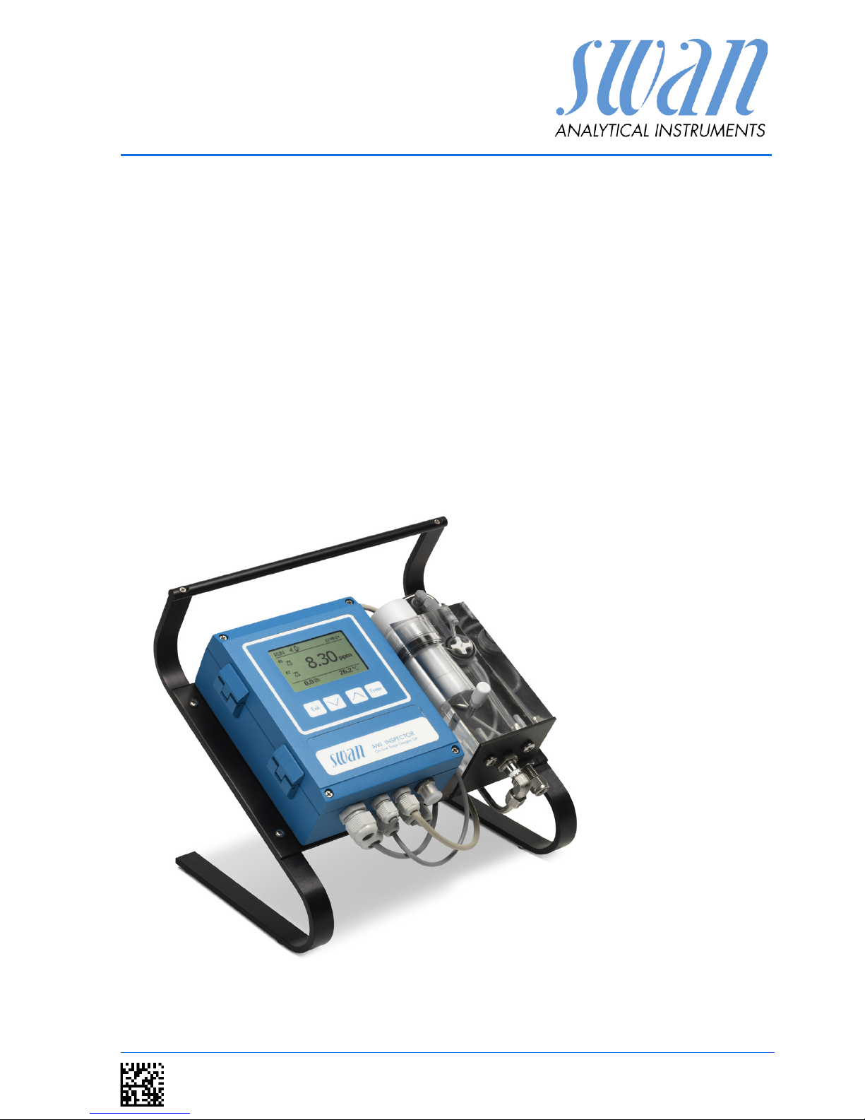
The portable AMI INSPECTOR instrument is a complete monitoring
system mounted on a small panel with supporting stand and a rechargeable battery for stand-alone operation (>24h), designed as
an inspection equipment for quality assurance of online process
monitors.
Features General Features of AMI INSPECTORs are:
Battery life after full charge:
– >24h at full load (use of 3 relays, USB, signal output, logger)
– >36h at minimum load (use of logger only)
Charging time: approx. 6 hours
Controlled shut-down if battery is empty.
Display of remaining battery life in hours.
For longer battery life the back light of the LC Display is dis-
abled.
Continuous operation using power adapter. The battery
should be discharged at least once a month (normal usage
until the monitor automatically shuts down).
Battery The Li-Ion battery is located in the housing of the AMI transmitter.
See chapter Power Supply, p. 19 regarding power supply and
charging of the battery.
Safety features No data loss after power failure, all data is saved in non-volatile
memory. Over voltage protection of in- and outputs.
Galvanic separation of measuring inputs and signal outputs.
USB interface Built in USB interface for logger download. Use the USB stick sup-
plied by Swan only (other USB sticks can dramatically reduce battery life).
Signal Output
(optional)
One signal output programmable for measured values (freely
scaleable, linear or bilinear) or as continuous control output (control
parameters programmable).
Current loop: 0/4–20 mA
Maximal burden: 510

8 A-96.250.701 / 140716
AMI INSPECTOR Oxygen
Product Description
Relay Two potential-free contacts programmable as limit switches for
measuring values, controllers or timer for system cleaning with automatic hold function.
Maximum load: 100 mA/ 50 VAC
Alarm Relay One potential free contact.
Alternatively:
Open during normal operation, closed on error and loss of
power.
Closed during normal operation, open on error and loss of
power.
Summary alarm indication for programmable alarm values and instrument faults.
Input For potential-free contact to freeze the measuring value or to inter-
rupt control in automated installations (hold function or remote-off)
Measuring
principle
Clark principle:
The sensor consists of one noble metal electrode (e.g. platinum or
gold), a reference electrode (mostly Ag/AgCl) and optionally a metal guard electrode.
The Clark-type electrode is the most widely used oxygen sensor for
measuring oxygen dissolved in a liquid. The basic principle is that
there is a cathode and an anode submersed in an electrolyte and a
voltage is applied between the two parts. Oxygen enters the sensor
through a permeable membrane by diffusion, and is reduced at the
cathode according to
O
2
+ 4e- + 2 H2O --> 4 OH
-
This reaction creates a measurable current. There is a linear correlation between the oxygen concentration and the electrical current.
The guard electrode is on the same voltage level as the cathode
but there is no current measurement. Oxygen which diffuses from
the electrolyte to the cathode is consumed by the guard electrode.
As a consequence, residual oxygen in the electrolyte will no more
disturb the measurement signal and the response time to low oxygen levels will be shorter.
Temperature
compensation
The measuring signal depends on temperature, but is automatically
compensated to 25 °C. The sample temperature is determined continuously by a temperature sensor inside the oxygen electrode.
AMI INSPECTOR Oxygen
Product Description
A-96.250.701 / 140716 9
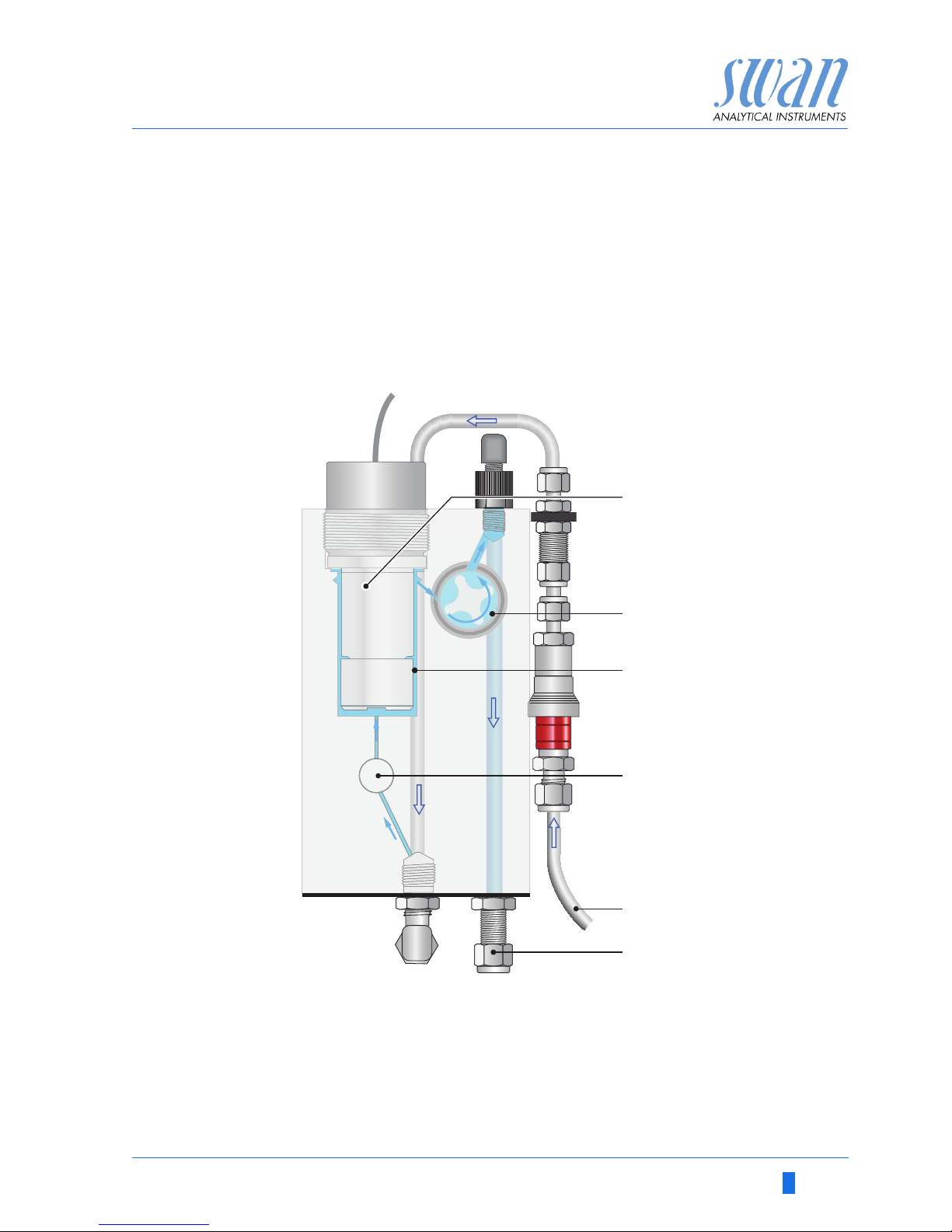
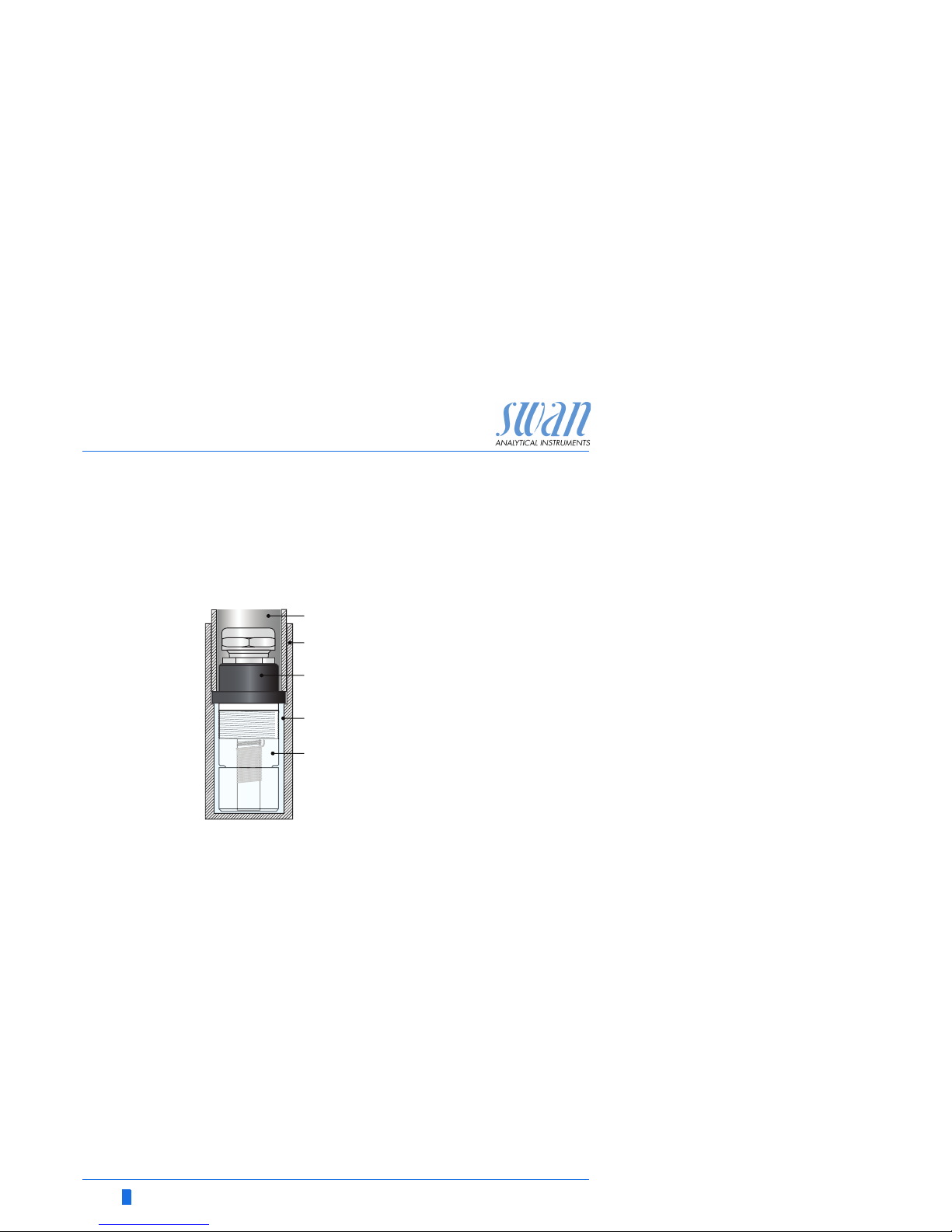
Fluidics Swansensor oxygen combined with QV-flow PMMA OTG flow cell.
The sample flows via sample inlet [E] through the flow regulating
valve [D], where the flow rate can be adjusted. Then the sample
flows into the measuring cell [C] were the Oxygen concentration
and temperature of the sample is measured.
The sample leaves the measuring cell via flow sensor [B] through
the sample outlet [F].
A
B
C
Oxygen sensor
Flow sensor
Flow cell
D
E
F
Flow regulating valve
Sample inlet
Sample outlet
A
B
C
D
E
F
10 A-96.250.701 / 140716
AMI INSPECTOR Oxygen
Product Description
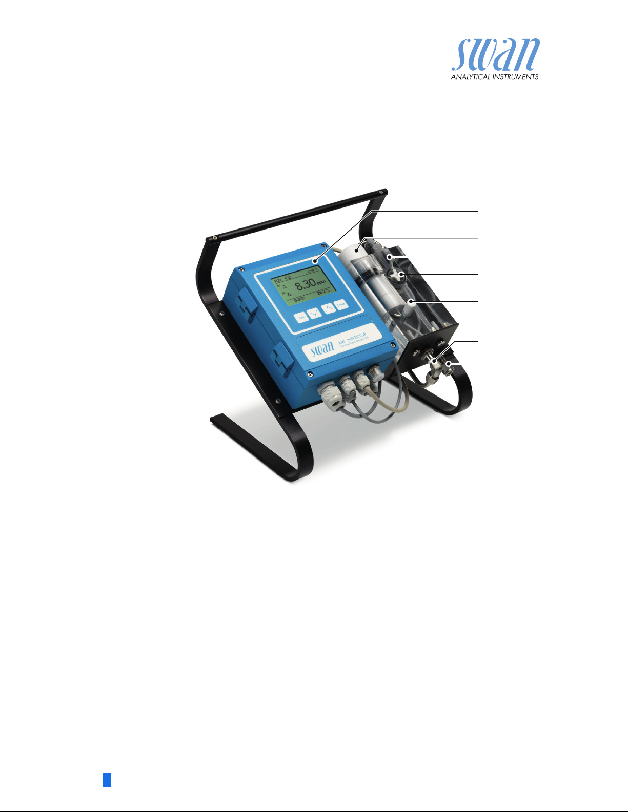
2.2. Instrument Overview
A
B
C
D
E
AMI Transmitter
Oxygen sensor
Flow cell
Flow sensor
Flow regulating valve
FGSample inlet
Sample outlet
A
B
D
C
F
G
E

AMI INSPECTOR Oxygen
Product Description
A-96.250.701 / 140716 11
2.3. Technical Data
Power Supply Battery
Use original, supplied power adapter only.
Voltage:
Power consumption:
Charging time:
Battery type:
85–265 VAC, 50/ 60 Hz
max. 20 VA
6h
Li-Ion
During charging protect from heat impact and keep splash-proof
(not IP66).
Operating time Stand-alone (Battery):
Connected adapter:
> 24h
continuous
Controlled shut-down when battery is empty, remaining time is displayed.
Electronics Aluminium with a protection degree of IP 66 / NEMA 4X
housing Ambient temperature:
Humidity:
Display:
-10 to +50 °C
10–90% rel., non condensing
backlit LCD, 75 x 45 mm
Sample
requirements
Flow rate:
Temperature:
Inlet pressure:
pH:
Suspended solids:
Outlet pressure:
8 to 25 l/h
up to 45 °C
0.2 to 1 bar
not lower than pH 4
less than 10 ppm
pressure free
Flow cell and
connection
Flow cell made of acrylic glass with built-in flow adjustment valve
and digital sample flow meter
Sample inlet:
Sample outlet:
1/4” Swagelok tube adapter
flexible tube 8x6 mm
Accuracy
Reproducibility
±1.5 % of measured value or ±0.2 ppb
±1 % of measured value or ±0.15 ppb

12 A-96.250.701 / 140716
AMI INSPECTOR Oxygen
Product Description
Sensor
Oxytrace G
Sensor for the measurement of dissolved oxygen in ultra pure
water. Precise oxygen measuring cell with integrated temperature
sensor and guard electrode for faster initial response time after
maintenance.
Technical data: Clark oxygen electrode
Cathode gold, anode silver, guard silver
Zero current-free electrode system
Robust 25 µm fluoropolymer diaphragm
Measuring
range:
0–20 ppm O
2
(25 °C)
Automatic range switching
Range
0.1 to 9.99 ppb
10 to 199.9 ppb
200 to 1999 ppb
2 to 20 ppm
0 – 200% saturation
Resolution
0.01 ppb
0.1 ppb
1.0 ppb
0.01 ppm
Accuracy: 0,3 % if calibration temperature = measuring temp. 1,5% at ± 10
°C deviation to cal. temperature
Precision:
Response time:
Minimal flow:
Operating tem-
perature:
± 1% of reading or ±0.15 ppb
t90 < 30 seconds (rising concentration)
50 cm/s Pressure resistance: 3 bar
max. 50 °C
Material:
Protection:
Weight:
polyacetal copolymer
IP 68
150 g

AMI INSPECTOR Oxygen
Installation
A-96.250.701 / 140716 13
3. Installation
3.1. Installation Check List
Check
Instrument’s specification must conform to your AC power
ratings. See External power adapter, p. 20.
Check if the battery is fully charged.
Installation
Connect the sample inlet and outlet, see Connecting Sample
Inlet and Outlet, p. 14.
Install the Swansensor Oxytrace G into the flow cell, see Install
the Swansensor Oxytrace G, p. 16.
Power-up
Open the flow regulating valve and adjust the sample flow to
8–25 l / h.
Switch on power.
Instrument
Setup
Program all parameters, see chapter 4.
Run-in period
Let the instrument run continuously for 1 h.
14 A-96.250.701 / 140716
AMI INSPECTOR Oxygen
Installation
3.2. Connecting Sample Inlet and Outlet
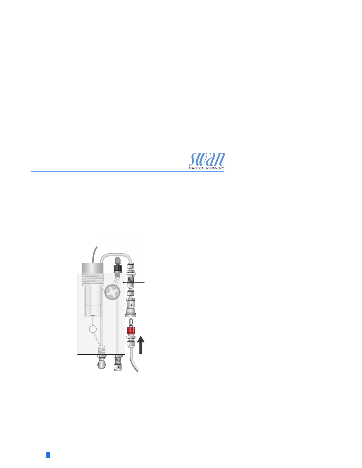
3.2.1 Connect the Sample Inlet to the Quick-Lock Coupling
The AMI INSPECTOR Oxygen is delivered with a quick-lock coupling. To connect the sample line to the AMI INSPECTOR Oxygen,
simply push the nipple into the quick-lock coupling.
A
B
C
D
Flow cell block
Quick-lock coupling
Nipple
Sample outlet
A
B
C
D
AMI INSPECTOR Oxygen
Installation
A-96.250.701 / 140716 15
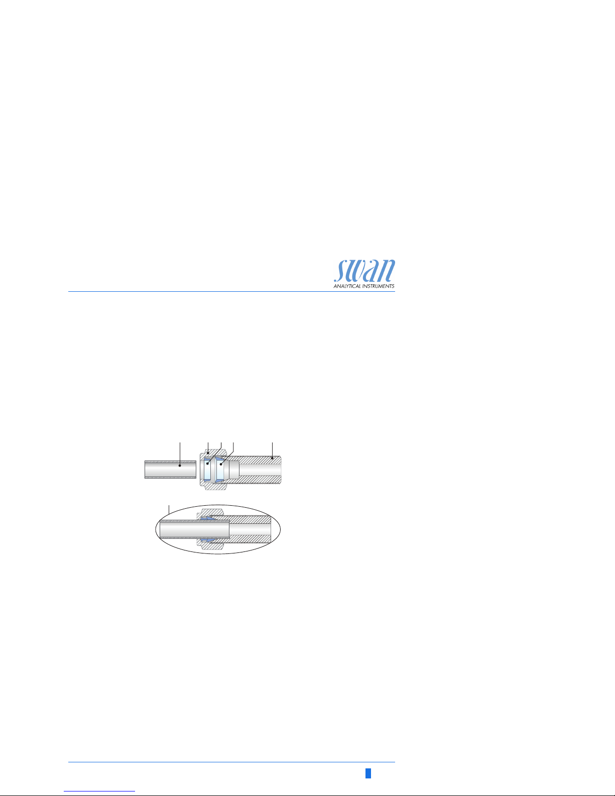
3.2.2 Connect the Sample Outlet
Installation 1 Loosen the union nut [B] but do not remove it.
2 Push the FEP tube [A] through the union nut [B] as far as it
reaches the stop of the threaded tube [E].
3 Tighten the union nut 1¾ rotation using an open ended spanner.
Hold Body from turning with a second wrench.
4 Put the FEP Tube into a pressure free drain with sufficient ca-
pacity.
A
B
C
FEP tube 8x 6
Union nut
Compression ferrule
D
E
F
Compression cone
Threaded tube
Tightened connection
ABCD E
F
16 A-96.250.701 / 140716
AMI INSPECTOR Oxygen
Installation
3.3 Install the Swansensor Oxytrace G
The Swansensor Oxytrace G is delivered with prefilled electrolyte
chamber [E]. A transport protection cap [B] filled with water [D]
keeps the sensor wet during transport and storage. To install the
sensor proceed as follows:
1 Unscrew the fixing sleeve [A].
2 Remove the transport protection cap [B].
3 Clean the Swansensor Oxytrace G [C] with water.
4 Install the Swansensor Oxytrace G into the flow cell
Connect the sensor cable to the transmitter, see Connection Dia-
gram, p. 18.
A
B
C
D
E
Fixing sleeve
Transport protection cap
Swansensor Oxytrace G
Water
Sensor cap filled with electrolyte
A
B
C
D
E
AMI INSPECTOR Oxygen
Installation
A-96.250.701 / 140716 17
3.4. Electrical Connections
WARNING
Always turn off DC power before manipulating electric parts.
Make sure the power specification of the instrument corresponds to the power on site.
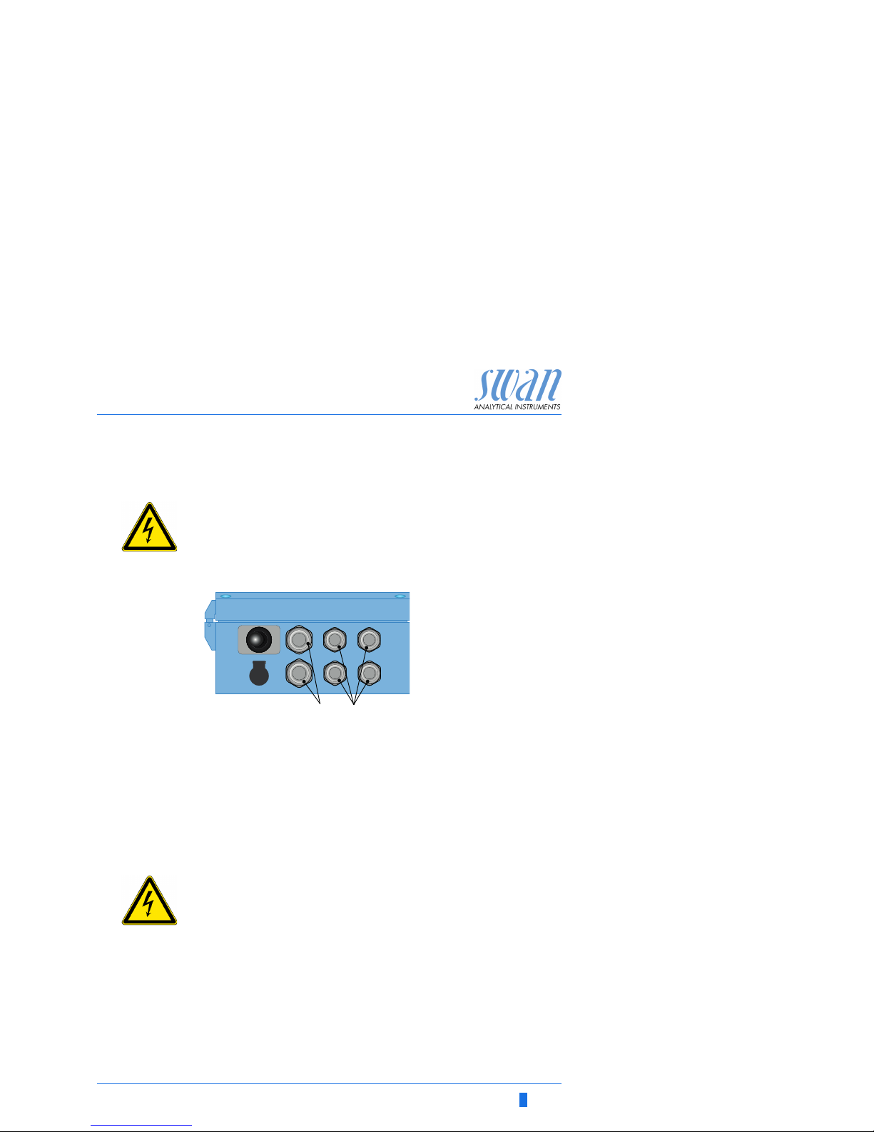
Cable
thicknesses
In order to comply with IP66, use the following cable thicknesses
NOTICE: Protect unused cable glands
Wire For Relays: Use max. 1.5 mm2 / AWG 14 stranded wire with
end sleeves.
For Signal Outputs and Input: Use 0.25 mm
2
/ AWG 23
stranded wire with end sleeves.
WARNING
External Voltage.
External supplied devices connected to relay 1 or 2 or to the
alarm relay can cause electrical shocks.
Make sure that the devices connected to the following con-
tacts are disconnected from the power before continuing the
installation.
– relay 1
– relay 2
– alarm relay
ABPG 9 cable gland: cable Ø
outer
4–8 mm
PG 7 cable gland: cable Ø
outer
3–6.5 mm
ON
OFF
AB
18 A-96.250.701 / 140716
AMI INSPECTOR Oxygen
Installation
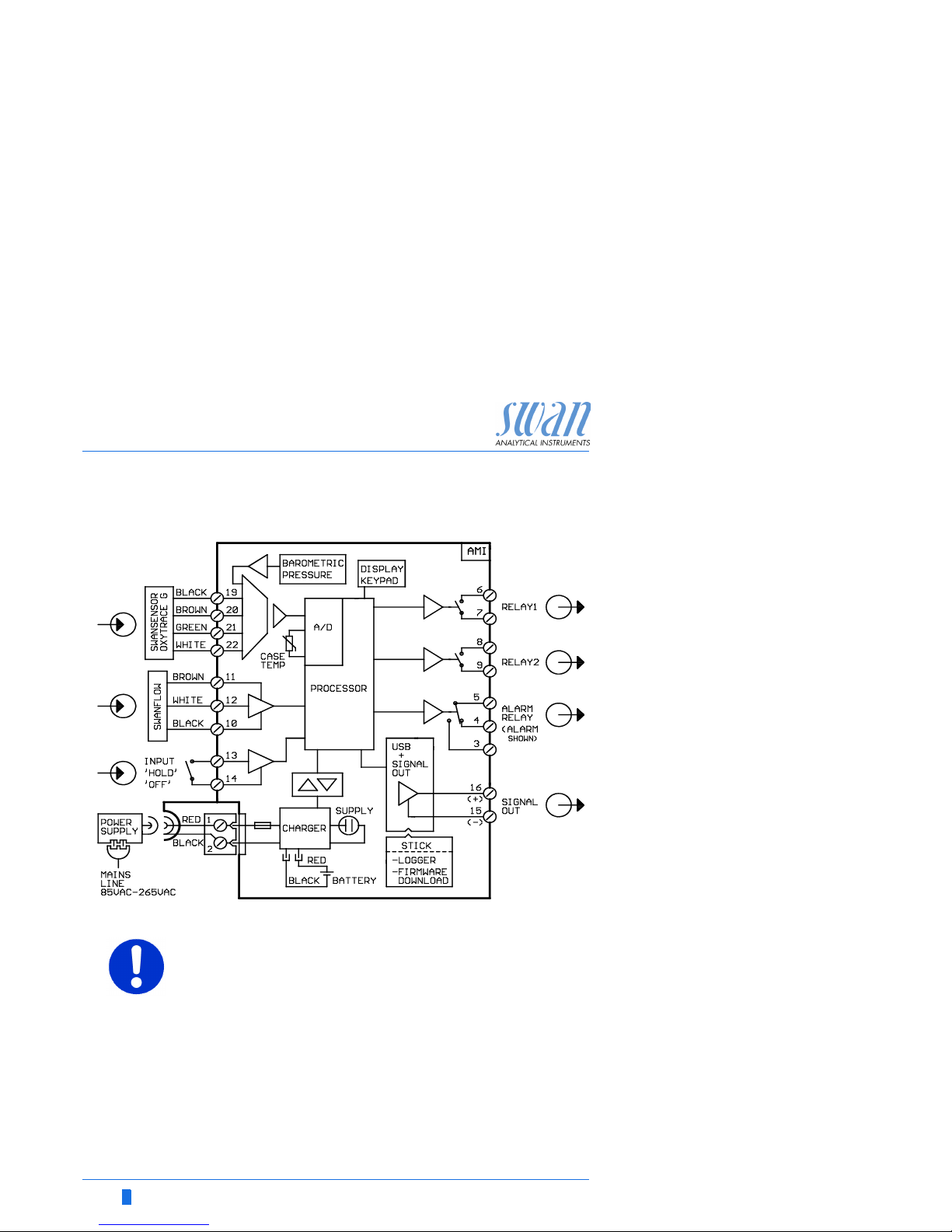
3.5. Connection Diagram
CAUTION
Use only the terminals shown in this diagram, and only for the
mentioned purpose. Use of any other terminals will cause short
circuits with possible corresponding consequences to material
and personnel.
AMI INSPECTOR Oxygen
Installation
A-96.250.701 / 140716 19
3.5.1 Power Supply
Contrary to all other Swan online process monitors the
AMI INSPECTOR transmitter is supplied with power by battery only. The rechargeable battery (Li-Ion) enables a stand-alone operation for at least 24 hours.
WARNING
Do not provide power directly to the transmitter as this will destroy the motherboard. All AMI INSPECTOR transmitters are
supplied with power by battery only.
Charging Use the original supplied power adapter to charge AMI INSPEC-
TOR only. Charging time: approx 6h.
Fully charged a stand-alone operating time of at least 24h is guar-
anteed:
>24h at full load (use of 3 relays, USB, signal output, logger)
>36h at minimal load (use of logger only)
In case that the battery is discharged completely the firmware will
automatically shut down.
Switch Power
ON - OFF
Switch the instrument ON or OFF using the toggle switch on the
transmitter.
Continuous
operation
For continuous operation use the power adapter as well.
CAUTION
If the AMI powers ON and then immediately shuts OFF, the
battery is empty. Do not hold the toggle switch in ON position,
as this can damage the battery.
CAUTION
During charging protect from heat impact and keep splash-
proof (plug of power adapter is not IP66).
Do not supply external devices, e.g. pumps, magnetic valves
or any other current consumers with AMI INSPECTOR
CAUTION
Use the original supplied power adapter to charge AMI IN-
SPECTOR only. Use of any other power adapter can damage
the battery or cause malfunction.
20 A-96.250.701 / 140716
AMI INSPECTOR Oxygen
Installation
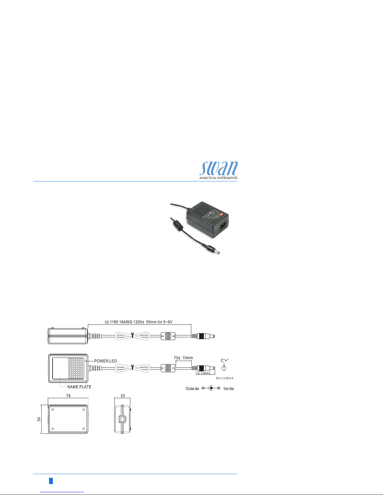
External
power adapter
Universal input range
85 - 265 VAC
Continuous short circuit protection
Over voltage protection
LED indicator for power on
2-pin AC inlet (IEC 320-C8) for
detachable country-specific power
cord
Power cords Two different power cords are supplied:
Power cord with type C plug (Europlug)
Power cord with type A plug (NEMA-1)
If a different plug type is needed, please purchase a suitable power
cord from your local supplier.
NOTICE: Do not use any plug adapters.
Dimensions
Unit: mm
AMI INSPECTOR Oxygen
Installation
A-96.250.701 / 140716 21
3.6. Relay Contacts
Programming of the relay contacts see 5.3 Relay Contacts, p. 59
3.6.1 Input
NOTICE: Use only potential-free (dry) contacts.
Terminals 13/14
If signal output is set to hold, measurement is interrupted if input is
active.
For programming see menu 5.3.4, p. 65
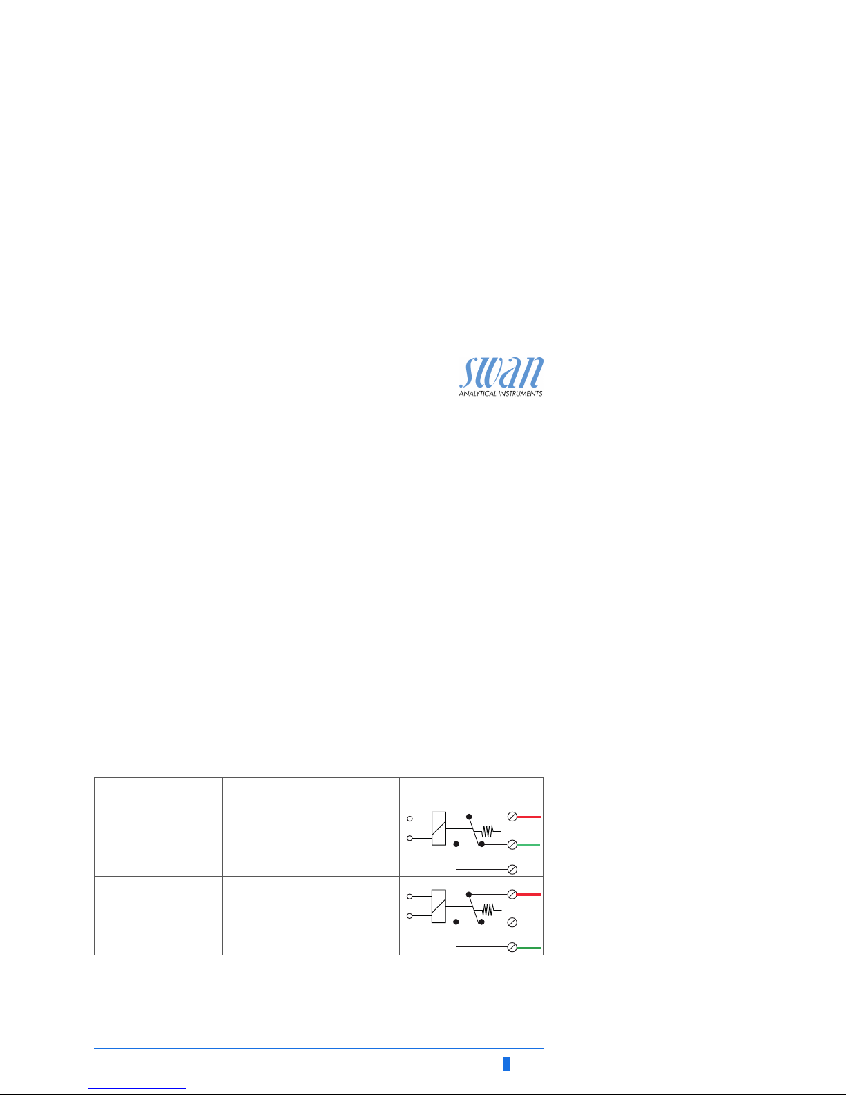
3.6.2 Alarm Relay
NOTICE: For resistive loads only; do not use with capacitive or
inductive loads. Max. load 1 A / 250 VAC.
Alarm output for system errors.
Error codes see Error List, p. 42
Programming see menu 5.3.1, p. 59
NOTICE: With certain alarms and certain settings of the AMI
transmitter the alarm relay does not switch. The error, however,
is shown on the display.
1) usual use
Terminals Description Relay connection
NC
1)
Normally
Closed
5/4 Active (opened) during normal
operation.
Inactive (closed) on error and
loss of power.
NO
Normally
Open
5/3 Active (closed) during normal
operation.
Inactive (opened) on error and
loss of power.
4
3
5
0V
1)
4
3
5
0V
 Loading...