

Swann AMI Codes-II CC, AMI Codes-II TC Operator's Manual
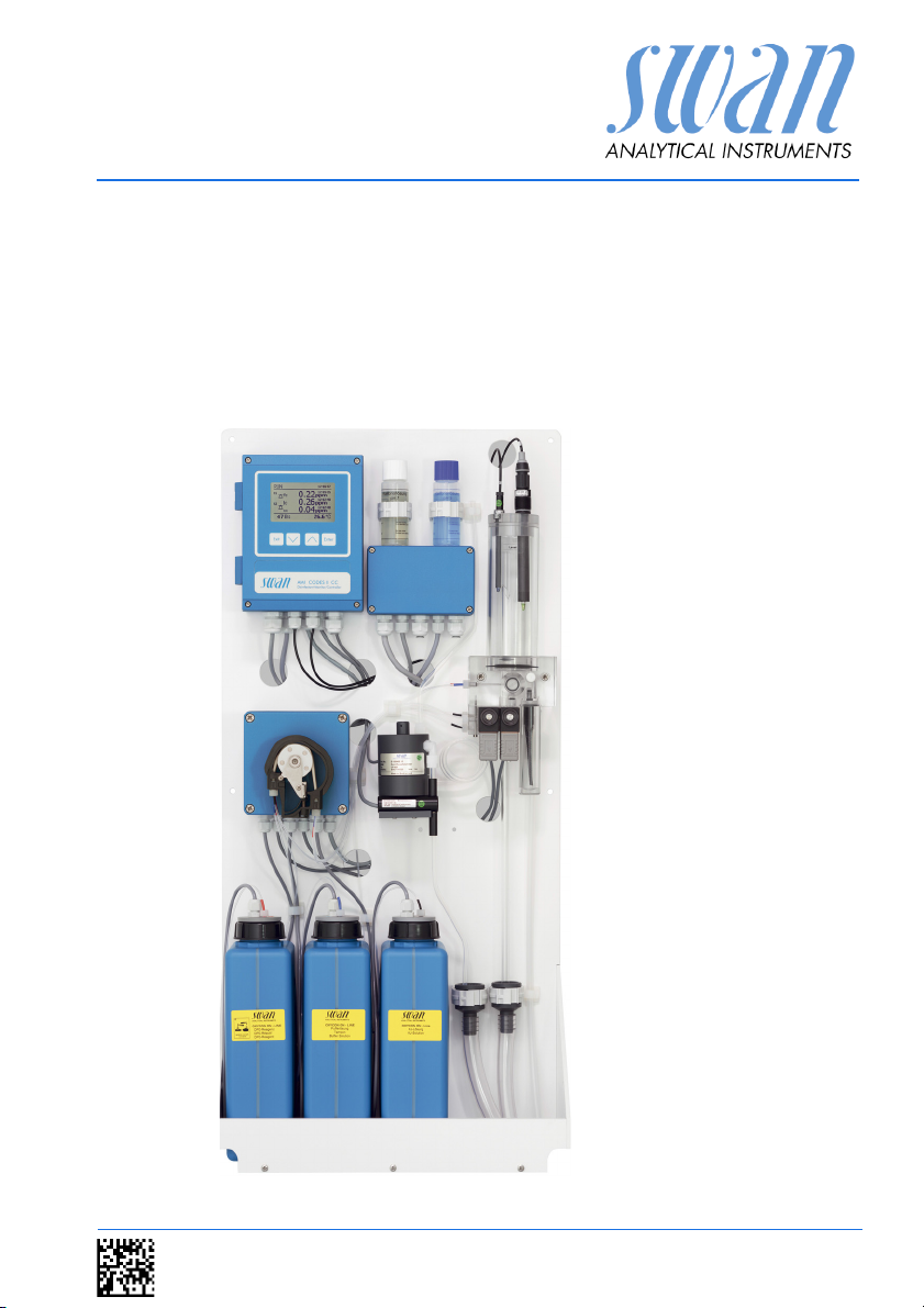
AMI Codes-II CC
Version 6.00 and higher
s Manual
Operator’
A-96.250.581 / 220616

Customer Support
SWAN and its representatives maintain a fully trained staff of technical specialists
around the world. For any technical question, contact your nearest
SWAN representative, or the manufacturer:
SWAN ANALYTISCHE INSTRUMENTE AG
Studbachstrasse 13
8340 Hinwil
Switzerland
Internet: www.swan.ch
E-mail: support@swan.ch
Document Status
Title:
ID:
Monitor AMI Codes-II CC Operator’s Manual
A-96.250.581
Revision Issue
00 April 2010
01 June 2010
02 Aug. 2013 Update to Rev. 5.40, main board V2.4
03 June 2016 Update to Rev. 6.00, main board V2.5
© 2016, SWAN ANALYTISCHE INSTRUMENTE AG, Switzerland, all rights reserved
subject to change without notice

AMI Codes-II CC
Table of Contents
1. Safety Instructions . . . . . . . . . . . . . . . . . . . . . . . . . . . . . . . . . . . 4
1.1. Warning Notices . . . . . . . . . . . . . . . . . . . . . . . . . . . . . . . . . . . . . . 5
1.2. General Safety Regulations . . . . . . . . . . . . . . . . . . . . . . . . . . . . . 7
1.3. Restrictions for use. . . . . . . . . . . . . . . . . . . . . . . . . . . . . . . . . . . . 8
2. Product Description . . . . . . . . . . . . . . . . . . . . . . . . . . . . . . . . . . 9
2.1. Instrument Specification . . . . . . . . . . . . . . . . . . . . . . . . . . . . . . . . 16
2.2. Instrument Overview. . . . . . . . . . . . . . . . . . . . . . . . . . . . . . . . . . . 18
3. Installation. . . . . . . . . . . . . . . . . . . . . . . . . . . . . . . . . . . . . . . . . . 19
3.1. Installation Check List. . . . . . . . . . . . . . . . . . . . . . . . . . . . . . . . . . 19
3.2. Mounting of Instrument Panel. . . . . . . . . . . . . . . . . . . . . . . . . . . . 20
3.3. Connecting Sample and Waste . . . . . . . . . . . . . . . . . . . . . . . . . . 21
3.3.1 FEP Tube at Sample Inlet . . . . . . . . . . . . . . . . . . . . . . . . . . . . . 21
3.3.2 FEP Tube at Sample Outlet . . . . . . . . . . . . . . . . . . . . . . . . . . . 21
3.4. Installation of Flow Cell. . . . . . . . . . . . . . . . . . . . . . . . . . . . . . . . . 22
3.5. Install the Option pH . . . . . . . . . . . . . . . . . . . . . . . . . . . . . . . . . . . 23
3.5.1 pH as Option ex works . . . . . . . . . . . . . . . . . . . . . . . . . . . . . . . 23
3.5.2 pH Option as Retrofit Kit . . . . . . . . . . . . . . . . . . . . . . . . . . . . . . 24
3.6. Electrical Connections . . . . . . . . . . . . . . . . . . . . . . . . . . . . . . . . . 27
3.6.1 Connection Diagram . . . . . . . . . . . . . . . . . . . . . . . . . . . . . . . . . 29
3.6.2 Power Supply . . . . . . . . . . . . . . . . . . . . . . . . . . . . . . . . . . . . . . 30
3.7. Input . . . . . . . . . . . . . . . . . . . . . . . . . . . . . . . . . . . . . . . . . . . . . . . 31
3.8. Relay Contacts . . . . . . . . . . . . . . . . . . . . . . . . . . . . . . . . . . . . . . . 31
3.8.1 Alarm Relay. . . . . . . . . . . . . . . . . . . . . . . . . . . . . . . . . . . . . . . . 31
3.8.2 Relay 1 and 2 . . . . . . . . . . . . . . . . . . . . . . . . . . . . . . . . . . . . . . 32
3.9. Signal Outputs . . . . . . . . . . . . . . . . . . . . . . . . . . . . . . . . . . . . . . . 34
3.9.1 Signal Output 1 and 2 (current outputs) . . . . . . . . . . . . . . . . . . 34
3.9.2 Signal Output 3 (optional) . . . . . . . . . . . . . . . . . . . . . . . . . . . . . 34
3.10. Interface Options . . . . . . . . . . . . . . . . . . . . . . . . . . . . . . . . . . . . . 35
3.10.1 Profibus/Modbus Interface . . . . . . . . . . . . . . . . . . . . . . . . . . . . 35
3.10.2 USB Interface . . . . . . . . . . . . . . . . . . . . . . . . . . . . . . . . . . . . . . 35
4. Instrument Setup . . . . . . . . . . . . . . . . . . . . . . . . . . . . . . . . . . . . 36
4.1. Prepare Reagents . . . . . . . . . . . . . . . . . . . . . . . . . . . . . . . . . . . . 36
4.2. Peristaltic Pump . . . . . . . . . . . . . . . . . . . . . . . . . . . . . . . . . . . . . . 36
4.3. Establish Sample Flow . . . . . . . . . . . . . . . . . . . . . . . . . . . . . . . . . 37
4.4. Fill or Flush Reagent System . . . . . . . . . . . . . . . . . . . . . . . . . . . . 38
4.5. Programming . . . . . . . . . . . . . . . . . . . . . . . . . . . . . . . . . . . . . . . . 38
4.6. Calibration . . . . . . . . . . . . . . . . . . . . . . . . . . . . . . . . . . . . . . . . . . 39
A-96.250.581 / 220616 1

AMI Codes-II CC
5. Operation. . . . . . . . . . . . . . . . . . . . . . . . . . . . . . . . . . . . . . . . . . . 40
5.1. Keys . . . . . . . . . . . . . . . . . . . . . . . . . . . . . . . . . . . . . . . . . . . . . . . 40
5.2. Display . . . . . . . . . . . . . . . . . . . . . . . . . . . . . . . . . . . . . . . . . . . . . 41
5.3. Software Structure . . . . . . . . . . . . . . . . . . . . . . . . . . . . . . . . . . . . 42
5.4. Changing Parameters and values. . . . . . . . . . . . . . . . . . . . . . . . . 43
6. Maintenance . . . . . . . . . . . . . . . . . . . . . . . . . . . . . . . . . . . . . . . . 44
6.1. Maintenance Schedule . . . . . . . . . . . . . . . . . . . . . . . . . . . . . . . . . 44
6.2. Stop of Operation for Maintenance. . . . . . . . . . . . . . . . . . . . . . . . 45
6.3. Refill or replace Reagents. . . . . . . . . . . . . . . . . . . . . . . . . . . . . . . 46
6.3.1 Reagents for measuring Free Chlorine and Total Chlorine . . . . 48
6.4. Verification . . . . . . . . . . . . . . . . . . . . . . . . . . . . . . . . . . . . . . . . . . 50
6.5. Calibration. . . . . . . . . . . . . . . . . . . . . . . . . . . . . . . . . . . . . . . . . . . 51
6.6. Cleaning the protective Filter . . . . . . . . . . . . . . . . . . . . . . . . . . . . 54
6.7. Cleaning the Photometer . . . . . . . . . . . . . . . . . . . . . . . . . . . . . . . 55
6.8. Cleaning the Flow Cell . . . . . . . . . . . . . . . . . . . . . . . . . . . . . . . . . 56
6.8.1 Disassemble the Flow Cell . . . . . . . . . . . . . . . . . . . . . . . . . . . . 57
6.8.2 Assemble the Flow Cell. . . . . . . . . . . . . . . . . . . . . . . . . . . . . . . 58
6.9. Maintenance of pH sensor . . . . . . . . . . . . . . . . . . . . . . . . . . . . . . 59
6.10. Tube Replacement . . . . . . . . . . . . . . . . . . . . . . . . . . . . . . . . . . . . 60
6.10.1 Replace the Pump Tubes . . . . . . . . . . . . . . . . . . . . . . . . . . . . . 60
6.10.2 Replace the Reagent Tubes . . . . . . . . . . . . . . . . . . . . . . . . . . . 62
6.11. Cleaning the solenoid valve . . . . . . . . . . . . . . . . . . . . . . . . . . . . . 63
6.12. Replacing Fuses . . . . . . . . . . . . . . . . . . . . . . . . . . . . . . . . . . . . . . 65
6.13. Longer Stop of Operation . . . . . . . . . . . . . . . . . . . . . . . . . . . . . . . 66
7. Troubleshooting . . . . . . . . . . . . . . . . . . . . . . . . . . . . . . . . . . . . . 67
7.1. General Instructions . . . . . . . . . . . . . . . . . . . . . . . . . . . . . . . . . . . 67
7.2. Calibration Errors . . . . . . . . . . . . . . . . . . . . . . . . . . . . . . . . . . . . . 68
7.2.1 Process calibration tc or fc . . . . . . . . . . . . . . . . . . . . . . . . . . . . 68
7.2.2 Process pH . . . . . . . . . . . . . . . . . . . . . . . . . . . . . . . . . . . . . . . . 68
7.2.3 Standard pH . . . . . . . . . . . . . . . . . . . . . . . . . . . . . . . . . . . . . . . 68
7.3. Error List . . . . . . . . . . . . . . . . . . . . . . . . . . . . . . . . . . . . . . . . . . . . 69
8. Program Overview . . . . . . . . . . . . . . . . . . . . . . . . . . . . . . . . . . . 73
8.1. Messages (Main Menu 1) . . . . . . . . . . . . . . . . . . . . . . . . . . . . . . . 73
8.2. Diagnostics (Main Menu 2) . . . . . . . . . . . . . . . . . . . . . . . . . . . . . . 74
8.3. Maintenance (Main Menu 3) . . . . . . . . . . . . . . . . . . . . . . . . . . . . . 75
8.4. Operation (Main Menu 4) . . . . . . . . . . . . . . . . . . . . . . . . . . . . . . . 76
8.5. Installation (Main Menu 5). . . . . . . . . . . . . . . . . . . . . . . . . . . . . . . 78
9. Program List and Explanations. . . . . . . . . . . . . . . . . . . . . . . . . 80
1 Messages. . . . . . . . . . . . . . . . . . . . . . . . . . . . . . . . . . . . . . . . . . 80
2 A-96.250.581 / 220616

AMI Codes-II CC
2 Diagnostics . . . . . . . . . . . . . . . . . . . . . . . . . . . . . . . . . . . . . . . . 80
3 Maintenance . . . . . . . . . . . . . . . . . . . . . . . . . . . . . . . . . . . . . . . 82
4 Operation. . . . . . . . . . . . . . . . . . . . . . . . . . . . . . . . . . . . . . . . . . 85
5 Installation . . . . . . . . . . . . . . . . . . . . . . . . . . . . . . . . . . . . . . . . . 87
10. Material Safety Data sheets . . . . . . . . . . . . . . . . . . . . . . . . . . . . 105
10.1. Reagents . . . . . . . . . . . . . . . . . . . . . . . . . . . . . . . . . . . . . . . . . . . 105
11. Default Values . . . . . . . . . . . . . . . . . . . . . . . . . . . . . . . . . . . . . . . 106
12. Index . . . . . . . . . . . . . . . . . . . . . . . . . . . . . . . . . . . . . . . . . . . . . . 110
13. Notes . . . . . . . . . . . . . . . . . . . . . . . . . . . . . . . . . . . . . . . . . . . . . . 112
A-96.250.581 / 220616 3

AMI Codes-II CC
Safety Instructions
AMI Codes-II CC - Operator’s Manual
This document describes the main steps for instrument setup, operation and maintenance.
1. Safety Instructions
General The instructions included in this section explain the potential risks
Targ et
audience
OM Location The AMI Operator’s Manual shall be kept in proximity of the instru-
Qualification,
Training
associated with instrument operation and provide important safety
practices designed to minimize these risks.
If you carefully follow the information contained in this section, you
can protect yourself from hazards and create a safer work environment.
More safety instructions are given throughout this manual, at the
respective locations where observation is most important.
Strictly follow all safety instructions in this publication.
Operator: Qualified person who uses the equipment
for its intended purpose.
Instrument operation requires thorough knowledge of applications,
instrument functions and software program as well as all applicable
safety rules and regulations.
ment.
To be qualified for instrument installation and operation, you must:
read and understand the instructions in this manual as well as
the Material Safety Data Sheets.
know the relevant safety rules and regulations.
4 A-96.250.581 / 220616
AMI Codes-II CC
Safety Instructions
1.1. Warning Notices
The symbols used for safety-related notices have the following significance:
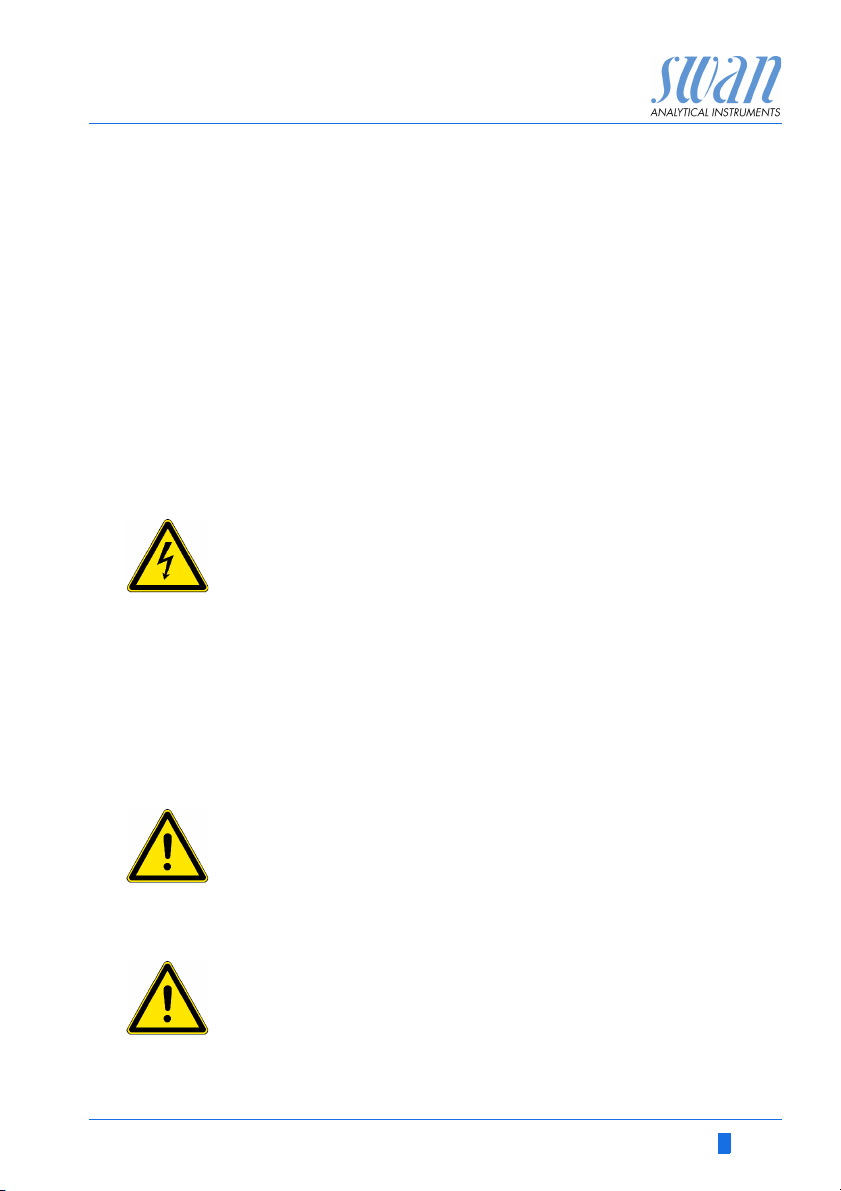
DANGER
Your life or physical wellbeing are in serious danger if such
warnings are ignored.
Follow the prevention instructions carefully.
WARNING
Severe injuries or damage to the equipment can occur if such
warnings are ignored.
Follow the prevention instructions carefully.
CAUTION
Damage to the equipment, minor injury, malfunctions or incorrect process can be the consequence if such warnings are ignored.
Follow the prevention instructions carefully.
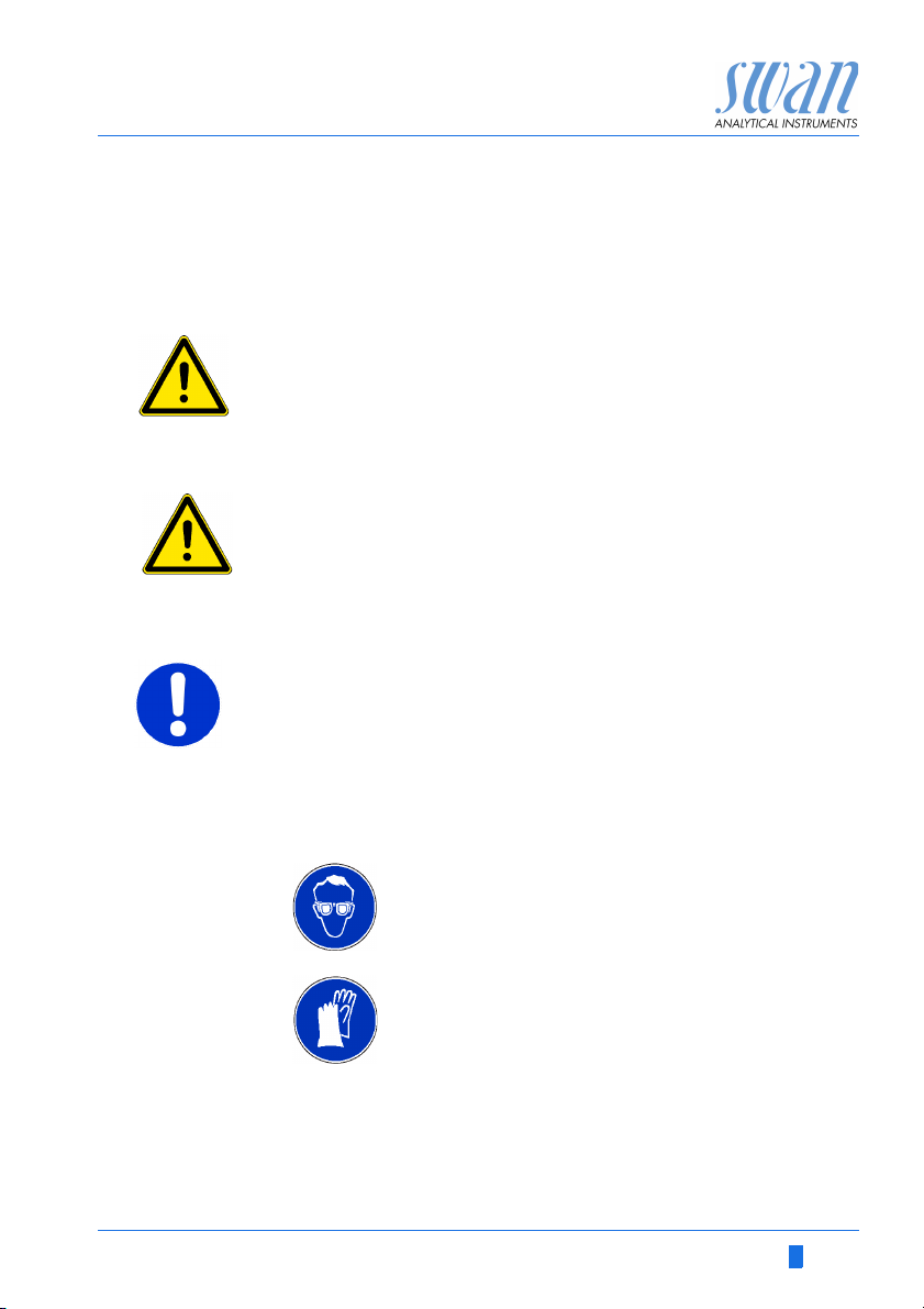
Mandatory
Signs
A-96.250.581 / 220616 5
The importance of the mandatory signs in this manual.
Safety goggles
Safety gloves
AMI Codes-II CC
Safety Instructions
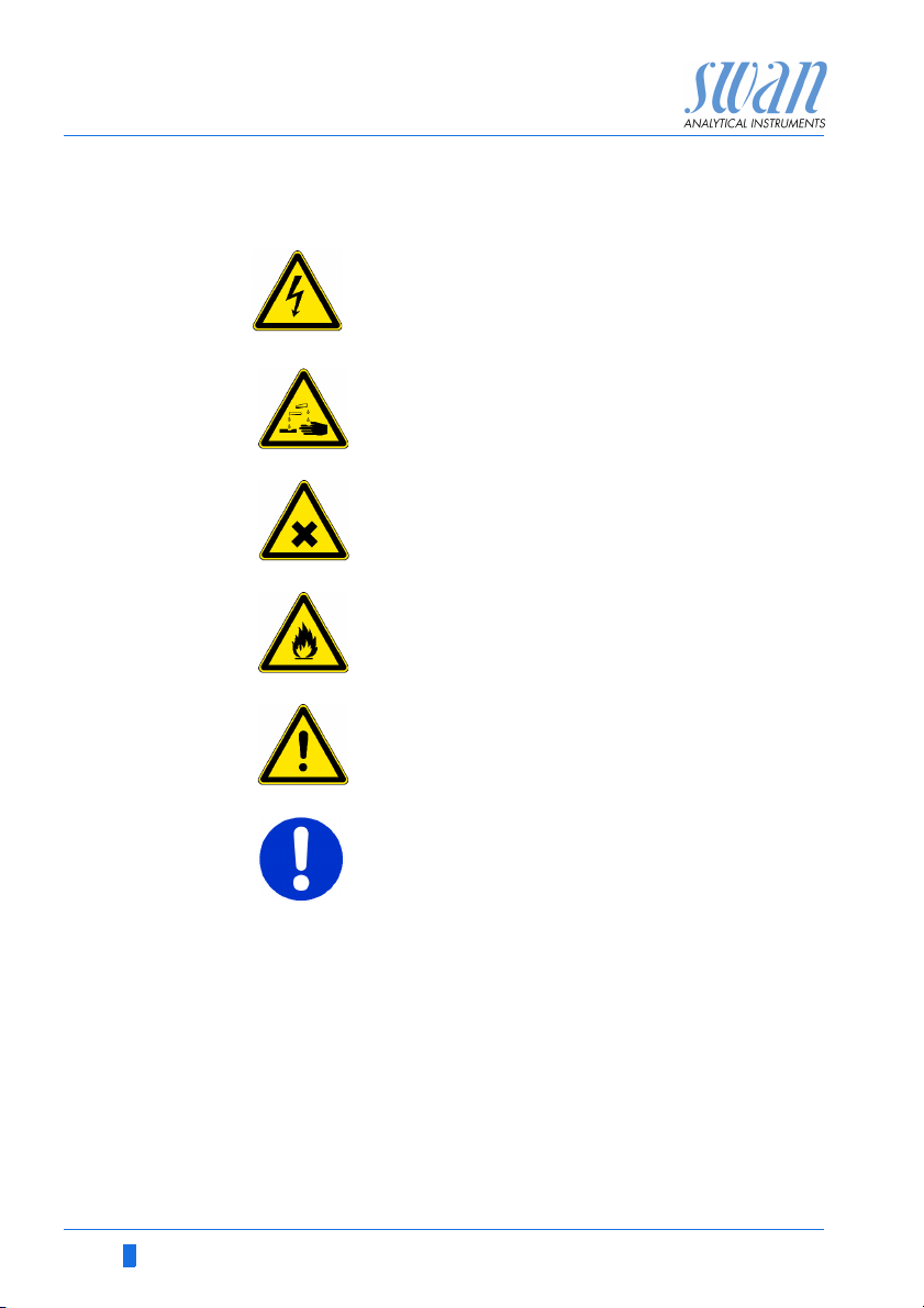
Warning Signs The importance of the warning signs in this manual.
Electrical shock hazard
Corrosive
Harmful to health
Flammable
Warning general
Attention general
6 A-96.250.581 / 220616
AMI Codes-II CC
Safety Instructions
1.2. General Safety Regulations
Legal
Requirements
Spare Parts
and
Disposables
Modifications Modifications and instrument upgrades shall only be carried out by
The user is responsible for proper system operation.
All precautions must be followed to ensure safe operation
of the instrument.
Use only official SWAN spare parts and disposables. If other parts
are used during the normal warranty period, the manufacturer’s
warranty is voided.
an authorized Service Technician. SWAN will not accept responsibility for any claim resulting from unauthorized modification or alteration.
WARNING
Risk of Electrical Shock
If proper operation is no longer possible, the instrument must be
disconnected from all power lines, and measures must be taken
to prevent inadvertent operation.
To prevent from electrical shock, always make sure that the
ground wire is connected.
Service shall be performed by authorized personnel only.
Whenever electronic service is required, disconnect instru-
ment power and power of devices connected to.
– relay 1,
– relay 2,
– alarm relay
WARNING
For safe instrument installation and operation you must read
and understand the instructions in this manual.
WARNING
Only SWAN trained and authorized personnel shall perform the
tasks described in this document.
A-96.250.581 / 220616 7
AMI Codes-II CC
Safety Instructions
1.3. Restrictions for use
The sample must not contain any particles, which may block the
flow cell. Sufficient sample flow is coercive for the correct function
of the instrument.
If the sample contains only little disinfectant concentrations, or
there is the danger of biological growth, we recommend to use the
optional Cleaning module from Swan.
WARNING
Health hazard
Some reagents are etching and can cause severe burns or eye
damage.
For safe handling of the reagents you must read and under-
stand the instructions in this manual, as well as the Material
Safety Data Sheets (MSDS)
Download
MSDS
The current Material Safety Data Sheets (MSDS) for the below listed Reagents are available for downloading at www.swan.ch.
OXYCON ON-LINE DPD
OXYCON ON-LINE Buffer
OXYCON ON-LINE KI
Buffer solution pH 4
Buffer solution pH 7
Buffer solution pH 9
8 A-96.250.581 / 220616

AMI Codes-II CC
Product Description
2. Product Description
Application
Range
Disinfectant
Measurement
Signal
Outputs
Relay Two potential-free contacts programmable as limit switches for
Alarm Relay One potential free contact.
The AMI Codes-II CC is a complete monitoring system for the automatic, continuous measurement and dosing control of chlorine
based on the DPD colorimetric method APHA 4500 Cl-G and on
EN ISO 7393-2.
It can be used for measuring disinfectants in:
Pools and sanitary water
Cooling water
Waste water effluent
It is also applicable for water containing additives like corrosion inhibitors, cyanuric acid and antiscaleants.
Determines free available chlorine, total chlorine and calculates
monochloramine, dichloramine and combined chlorine.
Necessary reagents:
Oxycon on-line DPD
Oxycon on-line Buffer
Oxycon on-line KI.
Disinfectant Measuring range Accuracy
Free available chlorine,
Total chlorine
Two signal outputs programmable for measured values (freely
scaleable, linear or bilinear) or as continuous control output (control
parameters programmable).
Current loop: 0/4–20 mA
Maximal burden: 510
Third signal output available as an option.
measuring values, controllers or timer for system cleaning with automatic hold function. Both contacts can be used as normally open
or normally closed.
Maximum load: 1 A/250 VAC
0.00– 1.00 ppm
1.00– 3.00 ppm
3.00– 5.00 ppm
± 0.01 ppm
± 0.06 ppm
± 0.20 ppm
A-96.250.581 / 220616 9

AMI Codes-II CC
Product Description
Alternatively:
Open during normal operation, closed on error and loss of
power.
Closed during normal operation, open on error and loss of
power.
Summary alarm indication for programmable alarm values and instrument faults.
Input For potential-free contact to freeze the measuring value or to inter-
rupt control in automated installations (hold function or remote-off)
Special
Feature
Safety
Features
Communica-
tion Interface
(optional)
Relay Box The AMI Relay Box is designed for the direct power supply and ac-
Cleaning
Module
Possibility to interrupt the measurement by activating the input. See
Program List and Explanations, 5.3.4, p. 102.
No data loss after power failure. All data is saved in non-volatile
memory. Over voltage protection of in- and outputs.Galvanic separation of measuring inputs and signal outputs.The analyzer is factory tested and ready for installation and operation.
USB Interface for logger download
RS485 with Fieldbus protocol Modbus or Profibus DP
pH Optional pH measurement is possible (pH correction or calibration).
tivation of dosing devices which are controlled with an AMI transmitter, e. g. to connect two solenoid valves or one motor valve for
disinfectant additions.
An optional Cleaning module is available.
10 A-96.250.581 / 220616
AMI Codes-II CC
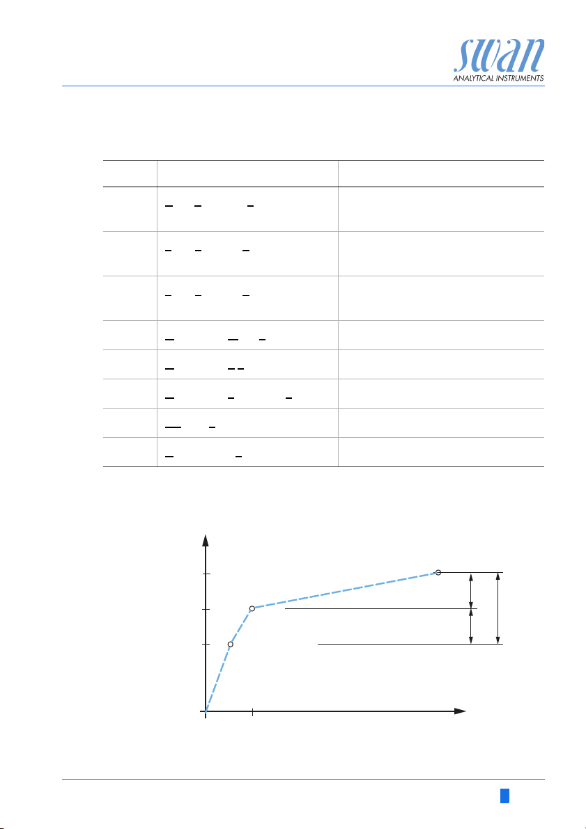
cdc
cmc
ccc
3-5 sec
DPD+Buffer
+KI
@ 2 min
0 sec
tc2
tc1
fac
2 min
Time
[ppm]
Value
Product Description
Glossary Used abbreviations to the chlorine forms measured:
Abbr. Te rm Comment
fac Free available chlorine Immediate reaction with DPD
(includes cyanuric acid fractions)
tc1 T
tc2 T
cmc C
cdc C
ccc C
pH/T pH
B/s B
otal chlorine 1 Immediate reaction of DPD + KJ
(mainly monochloramine)
otal chlorine 2 Reaction with DPD + KJ after 2
min. reaction
alculated monochloramine cmc = tc1 - fac
alculated dichloramine cdc = tc2 - tc1
alculated combined chlorine ccc = tc2 - fac
and Temperature (Optional)
ubbles per second Sample flow
A-96.250.581 / 220616 11
AMI Codes-II CC
Level
E
B
C
A
D
G
H
I
L
J
K
O
MN
PQ
R
F
Product Description
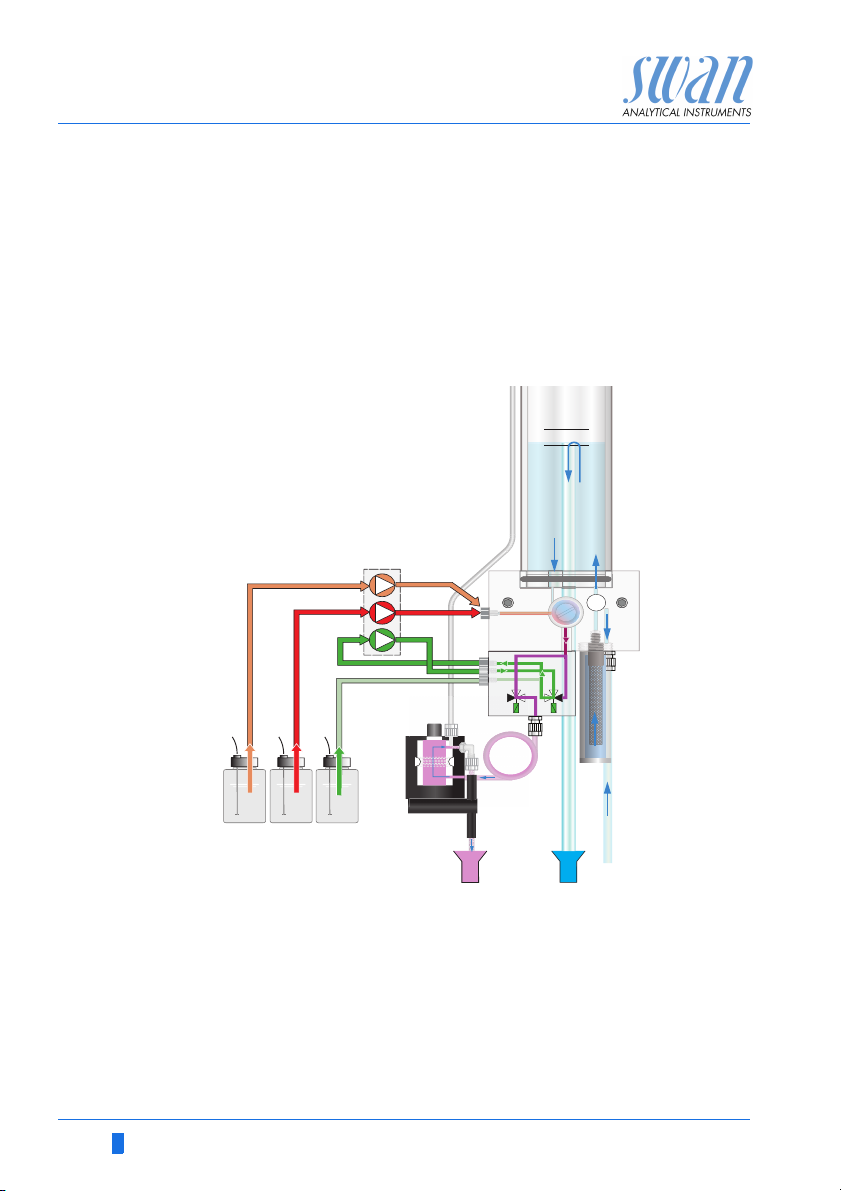
Fluidics The sample flows through the sample inlet [R] and the inlet filter [H]
into the constant head [A]. Adjust the flow regulating valve [F] so
that always a small part of the sample flows through the overflow
tube [B] into the constant head drain [Q].
Free available
chlorine
A part of the sample flows through the photometer inlet [C] into the
mixing chamber [E], where the reagents [M] and [N] are added by
the peristaltic pump [D] and mixed with the sample. The mixed
sample flows through the photometer [K] where the free available
chlorine is measured.
A
Constant head
B
Overflow tube
C
Photometer inlet
D
Peristaltic pump
E
Mixing chamber
F
Flow regulating valve
G
Solenoid valve V2
H
Inlet Filter
I
Photometer air inlet
12 A-96.250.581 / 220616
J
Solenoid valve V 1
K
Photometer
L
Air bubble detector
M
Reagent Oxycon on-line DPD
N
Reagent Oxycon on-line Buffer
O
Reagent Oxycon on-line KI
P
Photometer drain
Q
Constant head drain
R
Sample inlet
AMI Codes-II CC
Product Description
Total chlorine 1 After the measurement of free available chlorine is finished the so-
lenoid valve [G] is energized for a short time and reagent [O] is
added to determine total chlorine 1.
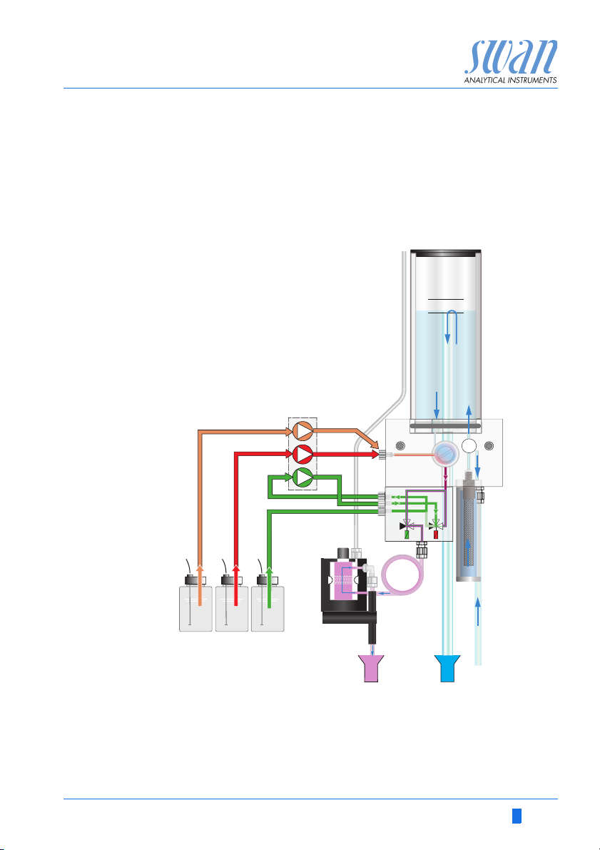
Total chlorine 2 To ensure the necessary reaction time of 2 min. for the determina-
tion of total chlorine 2, the sample flow is stopped by the solenoid
valve [J]. After the time has elapsed, total chlorine is measured and
solenoid valve [J] opens again.
A
Level
B
C
D
F
E
H
G
J
R
MN
I
K
O
L
PQ
After the measurement the sample flows through the outlet of the
photometer where it will be aerated through air inlet [I] to generate
bubbles. Then the sample flows through the bubble detector [L] into
the photometer drain [P].
A-96.250.581 / 220616 13

AMI Codes-II CC
Product Description
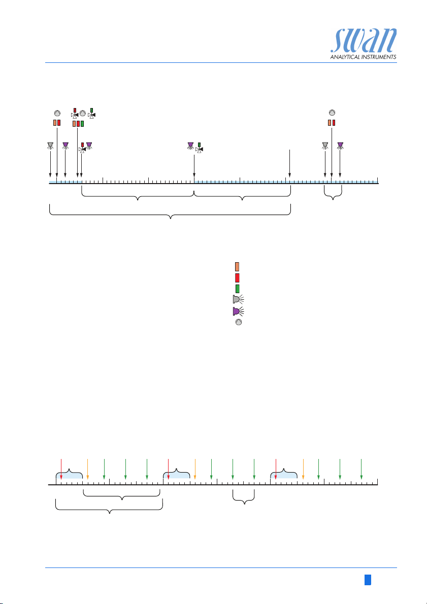
General It is distinguished between two different kinds of measurement:
Free available chlorine (fac) measurement
Overall measurement including free available chlorine (fac),
total chlorine 1 (tc1) and total chlorine 2 (tc2).
The Interval fac and the Interval tc2 can be set individually:
Interval fac between 0 and 12 min.
Interval tc2 between 0 and 60 min (overall measurement).
NOTICE: If the fac interval is set to zero, it is nevertheless
measured in the overall measurement.
The default setting for fac measurement interval is 5 min and for
overall measurement interval 20 min.
Time
sequence of an
overall
measurement
The blue bar represents the sample flow through the photometer.
At the beginning the solenoid valve [J] is de-energized and the
sample flows through the photometer. A short time before the measurement starts, a zero point measurement is performed. Then the
peristaltic pump starts and a small portion of the reagents “Oxycon
on-line DPD” and “OXYCON ON-LINE Buffer” is pumped into the
mixing chamber. During this time, the solenoid valve [G] is de-energized and the “Oxycon On-line KI” circulates between the peristaltic
pump and the valve block.
A short time after, if the mixture is in the photometer, the free available chlorine (fac) of the sample is measured.
After about 25 sec the peristaltic pump starts again. Now the solenoid valve [G] is energized and a small portion of the reagents
“Oxycon on-line DPD”, “OXYCON ON-LINE Buffer” and “Oxycon
On-line KI” is pumped into the mixing chamber.
A short time after, the solenoid valve [J] is energized and the sample flow through the potometer is stopped. Immediately after that,
the tc 1 is measured.
The “calculated monochloramine” (cmc) is calculated and displayed.
After about 120 sec the tc 2 is measured and then the “calculated
dichloramine” (cdc) and the “calculated combined chlorine” (ccc)
are calculated and displayed.
After the measurement is finished, the solenoid valve [J] is de-energized and sample flows through the photometer and a flush time of
2 minutes follows.
14 A-96.250.581 / 220616
AMI Codes-II CC
123 5678
min
4
tc 2
fac
ABDE
C
tc 1
GG
J
J
fac
F
G
H
fac fac fac
tc2
10020305060
min
40
Product Description
A
Reaction time for measuring tc 2
B
Flush time
C
Overall measurement time
D
Flush time end
E
fac measurement
G
Valve 1 for adding OXYCON ON-LINE KI
J
Valve 2 for closing photometer inlet
fac
Free available chlorine
tc1
Total chlorine 1
tc2
Total chlorine 2
OXYCON ON-LINE DPD
OXYCON ON-LINE Buffer
OXYCON ON-LINE KI
Zero point measurement
Sample measurement
Peristaltic pump active for a short
time
The programmed measuring intervals of tc2 [F] and fac [G] may
overlap each other.
The tc2 measurement has priority and therefore always takes place
in the programed measuring interval [F]. The fac measurement is
filled in the gaps [H] of the overall measurement and may be shifted
(orange arrow) in respect to programmed interval. If 2 fac measurements are programmed during a overall measurement one of them
is cancelled (red arrow).
A-96.250.581 / 220616 15

AMI Codes-II CC
Product Description
2.1. Instrument Specification
Power Supply Voltage:
Power consumption:
Electronics Aluminium with a protection degree of IP 66/NEMA 4X
housing Ambient temperature:
Limit range of operation:
Storage and transport:
Humidity:
Display:
Sample
requirements
On-site The analyzer site must permit connections to:
requirements Sample inlet:
Measuring Free chlorine, monochloramine, total residual chlorine
Range 0.00– 1.00 ppm
Flow rate:
Temperature:
Inlet pressure:
Outlet pressure:
NOTICE: No oil, no grease, no sand.
Sample outlet:
Max. Altitude:
1.00–3.00 ppm
3.00–5.00 ppm
pH measurement (optional)
2–12 pH 0.01 pH
100–240 VAC (± 10%)
50/60 Hz (± 5%)
or 24 VDC (± 10%)
max. 30 VA
-10 to +50 °C
-25 to +65 °C
-30 to +85 °C
10–90% rel., non condensing
backlit LCD, 75 x 45 mm
min. 10 l/h
5–50 °C (41–122 °F)
0.15–2 bar (2 – 28 PSI)
pressure free
Tube 6 x 8 mm
1/2” hose nozzle for flexible tube
diam. 20x15 mm
2000 m above sea level
± 0.01 ppm
± 0.06 ppm
± 0.2 ppm
16 A-96.250.581 / 220616
AMI Codes-II CC
Product Description
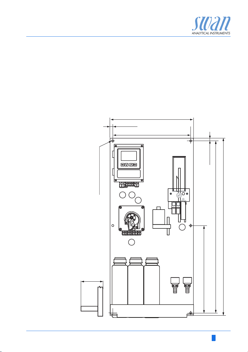
Dimensions Panel:
Mounting hole distance
Screws:
Weight:
400x850x 200 mm
374x824
5 mm or 6 mm diameter
12.0 kg / 26.5 lbs without reagents and
sample water
17.0 kg / 37.5 lbs with reagents and sample water
400 mm / 15¾”
13 mm / ½”
374 mm / 14¾”
AMI Codes II CC
6 x dia. 6.5 mm / ¼”
13 mm / ½”
”
16
/
7
3
412 mm / 16 ½ ”
30 mm / 1 ”
A-96.250.581 / 220616 17
/
16
850 mm / 33½”
824 mm / 32
AMI Codes-II CC
A
B
C
D
E
F
G
H
I
J
K
L
O
N
M
P
Q
R
S
Product Description
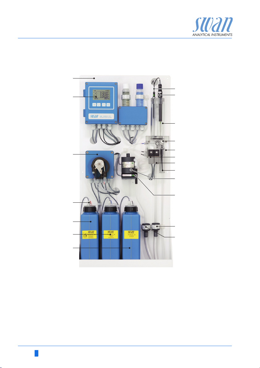
2.2. Instrument Overview
A
Panel
B
Transmitter
C
Peristaltic pump
D
Reagent level detector
E
Reagent Oxycon on-line DPD
F
Reagent Oxycon on-line Buffer
G
Reagent Oxycon on-line KI
H
Temperature sensor
I
pH sensor
J
Constant head
K
Flow regulating valve
L
Sample inlet
M
Valve 1 (Photometer)
N
Valve 2 (KI dosing)
O
Inlet filter
P
Photometer
Q
Air bubble detector
R
Constant head drain
S
Photometer drain
18 A-96.250.581 / 220616

AMI Codes-II CC
Installation
3. Installation
3.1. Installation Check List
Check Instrument’s specification must conform to the National Electrical
Code, all state and local codes, and all plant codes and standards
for electrical equipment.
On site requirements
Installation Mount the instrument in vertical position.
Electrical Wiring Do not switch on the Instrument until all electrical connections are
If ordered:
Option pH
Reagents Prepare reagents. See Refill or replace Reagents, p. 46.
Power-up Perform exactly in this order:
Instrument
Setup
Run-in period Let the instrument run continuously for 1 h.
pH sensor
calibration
100– 240 VAC ( 10%), 50/60 Hz ( 5%) or 24 VDC (±10%),
isolated power outlet with ground connection and 30 VA.
Sample line with min. 10 l / h and 0.15 – 2 bar.
Waste line with pressure free drain.
Display should be at eye-level.
Mount the filter, filter vessel, and constant head cover. Connect the
sample and waste line. See Connecting Sample and Waste, p. 21
made.
Connect all external devices like limit switches, current loops and
pumps.
Connect power cord.
See Electrical Connections, p. 27
See Install the Option pH, p. 23
Insert the suction lances combined with level detector.
Lock pump tubes.
Turn on the sample flow and wait until the flow cell is completely
filled.
Switch on power.
Start <Fill system>. See Fill or Flush Reagent System, p. 38
Program all parameters for external devices (interface, recorders,
etc.). Program all parameters for instrument operation (limits,
alarms, measuring interval).
If ordered: Calibrate pH sensor. See Calibration, p. 51
A-96.250.581 / 220616 19

AMI Codes-II CC
Installation
Process
calibration
3.2. Mounting of Instrument Panel
Mounting re-
quirements
Make 3 manual measurements. Use a high quality photometer,
e.g. Chematest from Swan. Calculate average value and compare
this value to the value, indicated by the AMI. If necessary, correct
the value. The zero point is done automatically before each measurement.
The first part of this chapter describes the preparing and placing of
the system for use.
The instrument must only be installed by trained personnel.
Mount the instrument in vertical position.
For ease of operation mount it so that the display is at eye
level.
For the installation a kit containing the following installation
material is available:
– 6 Screws 6x60 mm
– 6 Dowels
– 6 Washers 6.4/12 mm
The instrument is only intended for indoor installation.
For dimensions see Dimensions, p. 17.
20 A-96.250.581 / 220616
AMI Codes-II CC
B
C
D
A
A
Installation
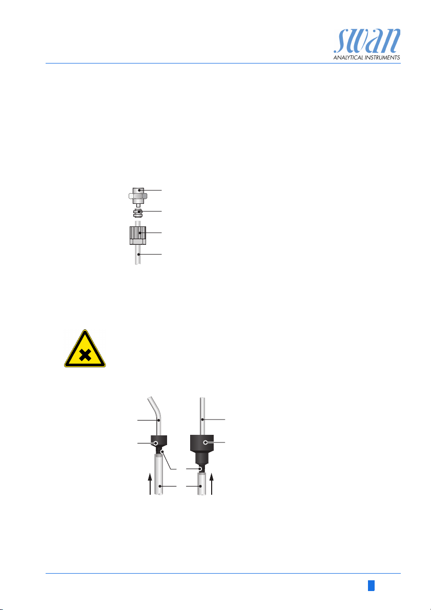
3.3. Connecting Sample and Waste
3.3.1 FEP Tube at Sample Inlet
Use plastic tube (FEP, PA, or PE 6 x 8 mm) to connect the sample
line.
Mounting of
SERTO fitting
3.3.2 FEP Tube at Sample Outlet
A
Screw connection
B
Compression ferrule
C
Knurled nut
D
Flexible tube
WARNING
Risk of water pollution
The drain of the photometer outlet contains DPD.
At no means recirculate it into the water system.
A
Tube from photometer
B
C
B
E
F
D
Drain Photometer
C
Tube from constant head
D
Drain constant head
E
Hose nozzles
F
1/2” tubes
Connect the 1/2” tubes [F] to the hose nozzles [E] and place it into
a pressure free drain with sufficient capacity.
A-96.250.581 / 220616 21
AMI Codes-II CC
Level
A
B
D
C
E
Installation
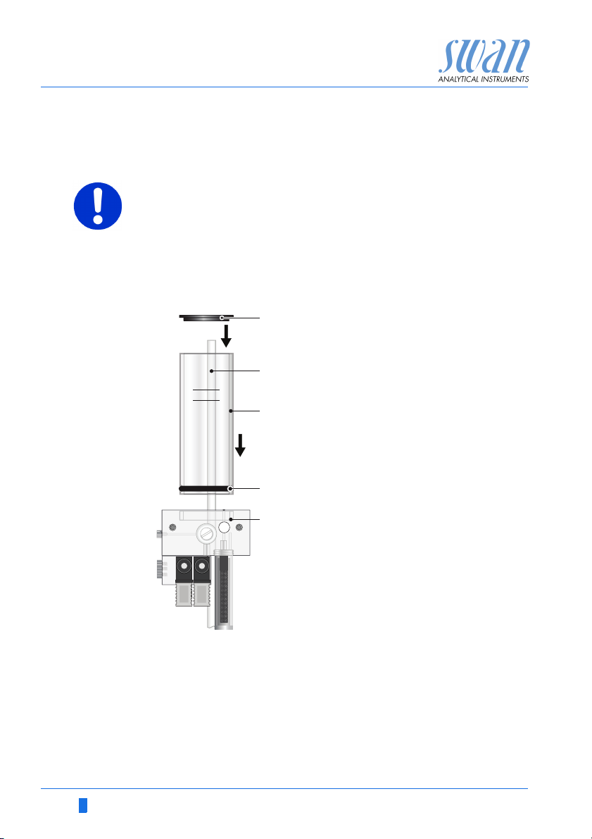
3.4. Installation of Flow Cell
CAUTION
Fragile Part
Handle the constant head tube with care.
To avoid damage during the transport, the constant head tube [C] of
the AMI Codes-II CC is not installed.
A
Constant head cover
B
Overflow tube
C
Constant head tube
D
Gasket
E
Flow cell block
To install the constant head tube proceed as follows:
1 Unpack the constant head tube [C].
2 Push the constant head tube into the flow cell block [E].
3 Put the constant head cover [A] onto the constant head tube.
4 Check if the overflow tube [B] is aligned with the upper Level
mark.
22 A-96.250.581 / 220616
AMI Codes-II CC
B
C
D
A
E
G
F
Installation
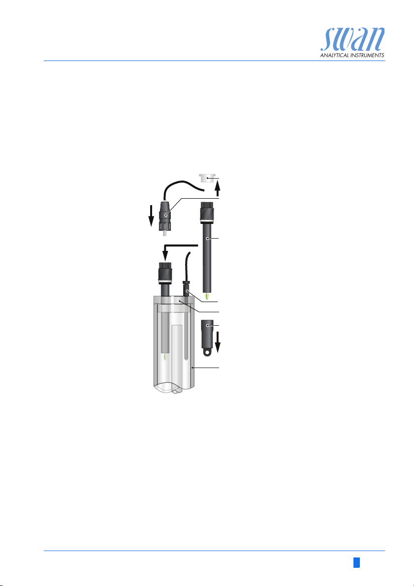
3.5. Install the Option pH
3.5.1 pH as Option ex works
If the pH option was ordered with the AMI Codes-II CC, the pH sensor cable as well as the temperature sensor are already connected
to the AMI transmitter.
A
Connector cap
B
Connector
C
pH Sensor
D
Temperature sensor
E
Constant head cover
F
Protective cap
G
Constant head
1 Carefully pull off the protective cap [F] from the pH sensor [C]
A-96.250.581 / 220616 23
by turning it clockwise.
2 Store the protective cap in safe place.
3 Rinse the pH sensor tip with clean water.
4 Insert the pH sensor into one of the holes in the constant head
cover [E].
5 Insert temperature sensor [D] into the small hole.
6 Remove the connector cap from the connector of the pH sen-
sor. Store it in safe place.
7 Screw the connector [B] onto the pH sensor.
AMI Codes-II CC
ABC
FE D
Installation
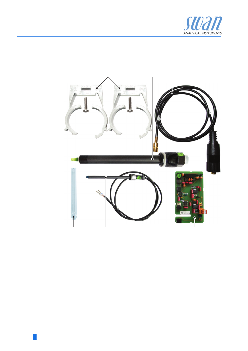
3.5.2 pH Option as Retrofit Kit
A
2 Clamps with screws
B
pH sensor
C
Sensor cable
D
Front end PCB
E
Temperature sensor
F
Short overflow tube
24 A-96.250.581 / 220616
AMI Codes-II CC
Level
A
B
C
D
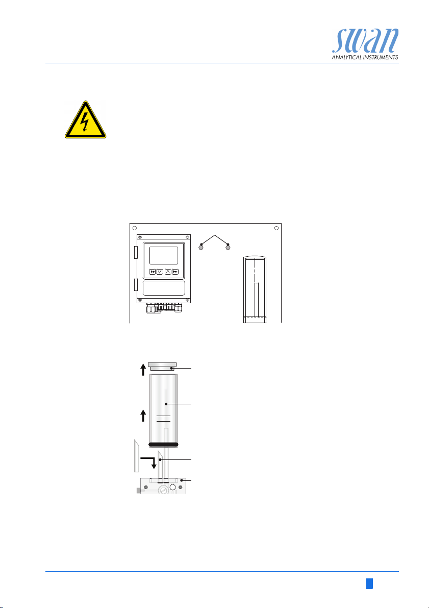
Installation
WARNING
Risk of electrical shock.
Do not perform any work on electrical components if the transmitter is switched on. Failure to follow safety instructions could
result in serious injury or death.
Always turn off AC power before manipulating electric parts.
1 Screw the clamps for calibration solution onto the panel. Use
the already drilled holes [A].
AMI Codes-II
2 Stop sample flow. Wait until flow cell is empty.
3 Switch off the AMI transmitter (disconnect power).
A
A
Constant head cover
B
Constant head tube
C
Short overflow tube
D
Flow cell block
4 Remove the constant head cover [A] and the constant head
tube [B] from the flow cell block [D].
5 Insert the short overflow tube [C] into the outlet hole leading to
the photometer.
6 Install the constant head tube and the constant head cover.
A-96.250.581 / 220616 25
AMI Codes-II CC
AB C
Installation
7 Open the cover of the AMI transmitter housing.
8 Install the front end PCB.
9 Feed the cable of the pH sensor through one of the cable
glands (see Cable thicknesses, p. 27) into the AMI transmitter
housing.
10 Connect it to the BNC socket.
11 Feed the cable of the Temperature sensor through one of the
cable glands into the AMI transmitter housing.
12 Connect the temperature sensor cable to the plug as follows:
Terminal 19: line
Terminal 20: shield.
13 Close the cover of the AMI transmitter housing.
14 Install the pH sensor, see pH as Option ex works, p. 23.
15 Turn on sample flow and wait until flow cell has been filled com-
pletely.
16 Switch power ON. The instrument automatically detects the
front end PCB during start-up.
A
Front end PCB
B
pH sensor plug
C
Temperature sensor plug
26 A-96.250.581 / 220616
AMI Codes-II CC
Installation
3.6. Electrical Connections
WARNING
Risk of electrical shock.
Do not perform any work on electrical components if the transmitter is switched on. Failure to follow safety instructions could
result in serious injury or death.
Always turn off AC power before manipulating electric parts.
Grounding requirements: Only operate the instrument from
an power outlet which has a ground connection.
Make sure the power specification of the instrument corre-
sponds to the power on site.
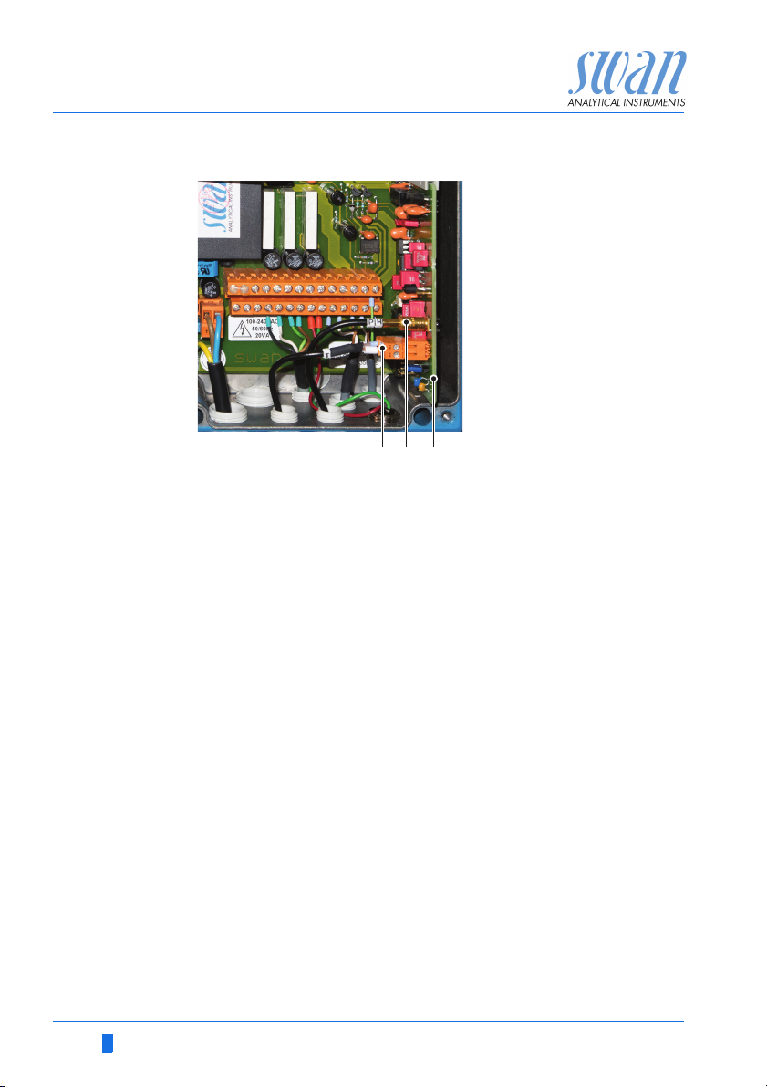
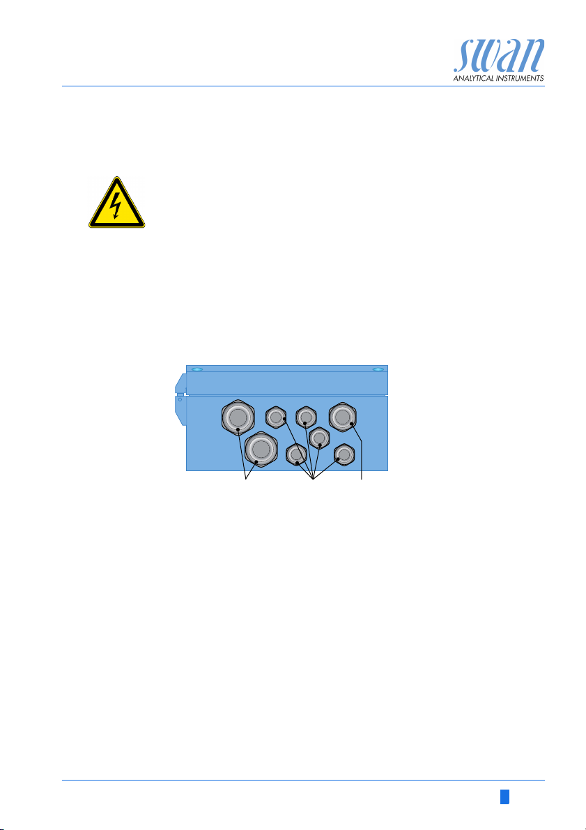
Cable
thicknesses
In order to comply with IP66, use the following cable thicknesses
ABC
PG 11 cable gland: cable Ø
A
B
PG 7 cable gland: cable Ø
C
PG 9 cable gland: cable Ø
outer
3–6.5 mm
outer
4–8 mm
outer
5–10 mm
NOTICE: Protect unused cable glands
Wire For Power and Relays: Use max. 1.5 mm
stranded wire with end sleeves.
For Signal Outputs and Input: Use 0.25 mm
2
/ AWG 14
2
/ AWG 23
stranded wire with end sleeves.
A-96.250.581 / 220616 27
AMI Codes-II CC
Installation
WARNING
External Voltage.
External supplied devices connected to relay 1 or 2 or to the
alarm relay can cause electrical shocks
Make sure that the devices connected to the following con-
tacts are disconnected from the power before resuming installation.
–relay 1
–relay 2
– alarm relay
WARNING
To prevent from electrical shock, do not connect the instrument
to the power unless the ground wire (PE) is connected.
Do not connect unless specifically instructed to do so.
WARNING
The mains of the AMI Transmitter must be secured by a main
switch and appropriate fuse or circuit breaker.
28 A-96.250.581 / 220616
 Loading...