

Page 1
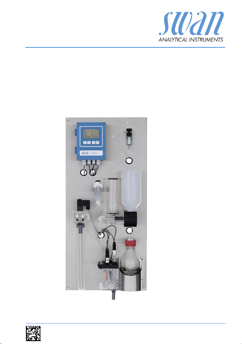
AMI Sodium P
Version 6.00 and higher
s Manual
Operator’
A-96.250.211 / 200416
Page 2

Customer Support
SWAN and its representatives maintain a fully trained staff of technical specialists
around the world. For any technical question, contact your nearest
SWAN representative, or the manufacturer:
SWAN ANALYTISCHE INSTRUMENTE AG
Studbachstrasse 13
8340 Hinwil
Switzerland
Internet: www.swan.ch
E-mail: support@swan.ch
Document Status
Title:
ID:
Monitor AMI Sodium P Operator’s Manual
A-96.250.211
Revision Issue
00 April 2005 First edition
04 October 2011 Update to Firmware Release 4.50
05 April 2014 Main board V2.4, Update to Firmware Release 5.40
06 April 2016 Main board V2.5, Update to Firmware Release 6.00
© 2016, SWAN ANALYTISCHE INSTRUMENTE AG, Switzerland, all rights reserved
subject to change without notice
Page 3

AMI Sodium P
Table of Contents
1. Safety Instructions . . . . . . . . . . . . . . . . . . . . . . . . . . . . . . . . . . . 4
1.1. Warning Notices . . . . . . . . . . . . . . . . . . . . . . . . . . . . . . . . . . . . . . 5
1.2. General Safety Regulations . . . . . . . . . . . . . . . . . . . . . . . . . . . . . 7
1.3. Restrictions for use. . . . . . . . . . . . . . . . . . . . . . . . . . . . . . . . . . . . 8
2. Product Description . . . . . . . . . . . . . . . . . . . . . . . . . . . . . . . . . . 9
2.1. Instrument Specification . . . . . . . . . . . . . . . . . . . . . . . . . . . . . . . . 13
2.2. Instrument Overview. . . . . . . . . . . . . . . . . . . . . . . . . . . . . . . . . . . 16
3. Installation. . . . . . . . . . . . . . . . . . . . . . . . . . . . . . . . . . . . . . . . . . 17
3.1. Installation Check List. . . . . . . . . . . . . . . . . . . . . . . . . . . . . . . . . . 17
3.2. Mounting of Instrument Panel. . . . . . . . . . . . . . . . . . . . . . . . . . . . 18
3.3. Connect Sample and Waste . . . . . . . . . . . . . . . . . . . . . . . . . . . . . 19
3.3.1 FEP Tube at Sample Inlet . . . . . . . . . . . . . . . . . . . . . . . . . . . . . 19
3.3.2 Sample Outlet . . . . . . . . . . . . . . . . . . . . . . . . . . . . . . . . . . . . . . 19
3.4. Install Sensors . . . . . . . . . . . . . . . . . . . . . . . . . . . . . . . . . . . . . . . 20
3.4.1 Install the Sodium Electrode . . . . . . . . . . . . . . . . . . . . . . . . . . . 21
3.4.2 Install the Reference Electrode . . . . . . . . . . . . . . . . . . . . . . . . . 23
3.4.3 Install the pH Electrode . . . . . . . . . . . . . . . . . . . . . . . . . . . . . . . 27
3.4.4 Install the Temperature Sensor. . . . . . . . . . . . . . . . . . . . . . . . . 28
3.4.5 Install reagent bottle . . . . . . . . . . . . . . . . . . . . . . . . . . . . . . . . . 28
3.5. Install 2nd Sample Stream (Option) . . . . . . . . . . . . . . . . . . . . . . . 29
3.5.1 Connect the solenoid valve . . . . . . . . . . . . . . . . . . . . . . . . . . . . 30
3.5.2 Firmware settings for 2nd sample stream option . . . . . . . . . . . 31
3.6. AMI Sodium P connected to a Sample Sequencer . . . . . . . . . . . 32
3.7. Electrical Connections . . . . . . . . . . . . . . . . . . . . . . . . . . . . . . . . . 33
3.7.1 Connection Diagram . . . . . . . . . . . . . . . . . . . . . . . . . . . . . . . . . 35
3.8. Relay Contacts . . . . . . . . . . . . . . . . . . . . . . . . . . . . . . . . . . . . . . . 37
3.8.1 Input . . . . . . . . . . . . . . . . . . . . . . . . . . . . . . . . . . . . . . . . . . . . . 37
3.8.2 Alarm Relay. . . . . . . . . . . . . . . . . . . . . . . . . . . . . . . . . . . . . . . . 37
3.8.3 Relay 1 and 2 . . . . . . . . . . . . . . . . . . . . . . . . . . . . . . . . . . . . . . 38
3.9. Signal Outputs . . . . . . . . . . . . . . . . . . . . . . . . . . . . . . . . . . . . . . . 40
3.9.1 Signal Output 1 and 2 (current outputs) . . . . . . . . . . . . . . . . . . 40
3.10. Interface Options . . . . . . . . . . . . . . . . . . . . . . . . . . . . . . . . . . . . . 40
3.10.1 Signal Output 3 . . . . . . . . . . . . . . . . . . . . . . . . . . . . . . . . . . . . . 41
3.10.2 Profibus, Modbus Interface . . . . . . . . . . . . . . . . . . . . . . . . . . . . 42
3.10.3 USB Interface . . . . . . . . . . . . . . . . . . . . . . . . . . . . . . . . . . . . . . 42
3.11. Connection of Sensors . . . . . . . . . . . . . . . . . . . . . . . . . . . . . . . . . 43
A-96.250.211 / 200416 1
Page 4

AMI Sodium P
4. Instrument Setup . . . . . . . . . . . . . . . . . . . . . . . . . . . . . . . . . . . . 44
4.1. Install Reagent Bottle . . . . . . . . . . . . . . . . . . . . . . . . . . . . . . . . . . 44
4.2. Establish Sample Flow . . . . . . . . . . . . . . . . . . . . . . . . . . . . . . . . . 45
4.3. Switch on Power . . . . . . . . . . . . . . . . . . . . . . . . . . . . . . . . . . . . . . 46
4.4. Programming . . . . . . . . . . . . . . . . . . . . . . . . . . . . . . . . . . . . . . . . 46
4.5. Check Outputs and Relays . . . . . . . . . . . . . . . . . . . . . . . . . . . . . . 46
4.6. Perform a calibration. . . . . . . . . . . . . . . . . . . . . . . . . . . . . . . . . . . 46
5. Operation. . . . . . . . . . . . . . . . . . . . . . . . . . . . . . . . . . . . . . . . . . . 47
5.1. Keys, Display . . . . . . . . . . . . . . . . . . . . . . . . . . . . . . . . . . . . . . . . 47
5.2. Software Structure . . . . . . . . . . . . . . . . . . . . . . . . . . . . . . . . . . . . 49
5.3. Changing Parameters and Values . . . . . . . . . . . . . . . . . . . . . . . . 50
5.4. Grab Sample. . . . . . . . . . . . . . . . . . . . . . . . . . . . . . . . . . . . . . . . . 51
6. Maintenance . . . . . . . . . . . . . . . . . . . . . . . . . . . . . . . . . . . . . . . . 52
6.1. Maintenance Schedule . . . . . . . . . . . . . . . . . . . . . . . . . . . . . . . . . 52
6.2. Stop of Operation for Maintenance. . . . . . . . . . . . . . . . . . . . . . . . 52
6.3. Maintenance of Sodium Electrode . . . . . . . . . . . . . . . . . . . . . . . . 53
6.4. Maintenance of Reference Electrode . . . . . . . . . . . . . . . . . . . . . . 55
6.5. Maintenance of pH Sensor . . . . . . . . . . . . . . . . . . . . . . . . . . . . . . 56
6.6. Maintenance of Solenoid Valve . . . . . . . . . . . . . . . . . . . . . . . . . . 57
6.7. Maintenance of Flow Cell and Constant Head . . . . . . . . . . . . . . . 59
6.7.1 Cleaning the Flow cell . . . . . . . . . . . . . . . . . . . . . . . . . . . . . . . . 60
6.7.2 Cleaning the Constant Head . . . . . . . . . . . . . . . . . . . . . . . . . . . 61
6.8. Replace the Air Filter . . . . . . . . . . . . . . . . . . . . . . . . . . . . . . . . . . 63
6.9. Prepare Standard . . . . . . . . . . . . . . . . . . . . . . . . . . . . . . . . . . . . . 64
6.10. Calibration. . . . . . . . . . . . . . . . . . . . . . . . . . . . . . . . . . . . . . . . . . . 64
6.10.1 pH Process Calibration . . . . . . . . . . . . . . . . . . . . . . . . . . . . . . . 64
6.10.2 Standard Sodium 1-Point-Calibration . . . . . . . . . . . . . . . . . . . . 65
6.10.3 2-Point-Calibration. . . . . . . . . . . . . . . . . . . . . . . . . . . . . . . . . . . 67
6.11. Tube Replacement . . . . . . . . . . . . . . . . . . . . . . . . . . . . . . . . . . . . 68
6.11.1 Tube Numbering . . . . . . . . . . . . . . . . . . . . . . . . . . . . . . . . . . . . 68
6.11.2 Replace the Reaction Tube. . . . . . . . . . . . . . . . . . . . . . . . . . . . 69
6.11.3 Replace the EPDM Seal and the Air Inlet Tube . . . . . . . . . . . . 70
6.12. Replacing Fuses . . . . . . . . . . . . . . . . . . . . . . . . . . . . . . . . . . . . . . 71
6.13. Longer Stop of Operation . . . . . . . . . . . . . . . . . . . . . . . . . . . . . . . 72
2 A-96.250.211 / 200416
Page 5

AMI Sodium P
7. Error List . . . . . . . . . . . . . . . . . . . . . . . . . . . . . . . . . . . . . . . . . . . 73
8. Program Overview . . . . . . . . . . . . . . . . . . . . . . . . . . . . . . . . . . . 76
8.1. Messages (Main Menu 1) . . . . . . . . . . . . . . . . . . . . . . . . . . . . . . . 76
8.2. Diagnostics (Main Menu 2). . . . . . . . . . . . . . . . . . . . . . . . . . . . . . 77
8.3. Maintenance (Main Menu 3). . . . . . . . . . . . . . . . . . . . . . . . . . . . . 78
8.4. Operation (Main Menu 4) . . . . . . . . . . . . . . . . . . . . . . . . . . . . . . . 79
8.5. Installation (Main Menu 5) . . . . . . . . . . . . . . . . . . . . . . . . . . . . . . 79
9. Program List and Explanations. . . . . . . . . . . . . . . . . . . . . . . . . 81
1 Messages . . . . . . . . . . . . . . . . . . . . . . . . . . . . . . . . . . . . . . . . . 81
2 Diagnostics . . . . . . . . . . . . . . . . . . . . . . . . . . . . . . . . . . . . . . . . 81
3 Maintenance . . . . . . . . . . . . . . . . . . . . . . . . . . . . . . . . . . . . . . . 83
4 Operation. . . . . . . . . . . . . . . . . . . . . . . . . . . . . . . . . . . . . . . . . . 84
5 Installation . . . . . . . . . . . . . . . . . . . . . . . . . . . . . . . . . . . . . . . . . 85
10. Material Safety Data Sheet. . . . . . . . . . . . . . . . . . . . . . . . . . . . . 101
10.1. Reagents . . . . . . . . . . . . . . . . . . . . . . . . . . . . . . . . . . . . . . . . . . . 101
11. Default Values . . . . . . . . . . . . . . . . . . . . . . . . . . . . . . . . . . . . . . . 102
12. Index . . . . . . . . . . . . . . . . . . . . . . . . . . . . . . . . . . . . . . . . . . . . . . 105
13. Notes . . . . . . . . . . . . . . . . . . . . . . . . . . . . . . . . . . . . . . . . . . . . . . 107
A-96.250.211 / 200416 3
Page 6

AMI Sodium P
Safety Instructions
AMI Sodium P - Operator’s Manual
This document describes the main steps for instrument setup, operation and maintenance.
1. Safety Instructions
General The instructions included in this section explain the potential risks
Targ et
audience
OM Location The AMI Operator’s Manual shall be kept in proximity of the instru-
Qualification,
Training
associated with instrument operation and provide important safety
practices designed to minimize these risks.
If you carefully follow the information contained in this section, you
can protect yourself from hazards and create a safer work environment.
More safety instructions are given throughout this manual, at the
respective locations where observation is most important.
Strictly follow all safety instructions in this publication.
Operator: Qualified person who uses the equipment
for its intended purpose.
Instrument operation requires thorough knowledge of applications,
instrument functions and software program as well as all applicable
safety rules and regulations.
ment.
To be qualified for instrument installation and operation, you must:
read and understand the instructions in this manual as well as
the Material Safety Data Sheets.
know the relevant safety rules and regulations.
4 A-96.250.211 / 200416
Page 7

AMI Sodium P
Safety Instructions
1.1. Warning Notices
The symbols used for safety-related notices have the following significance:
DANGER
Your life or physical wellbeing are in serious danger if such
warnings are ignored.
Follow the prevention instructions carefully.
WARNING
Severe injuries or damage to the equipment can occur if such
warnings are ignored.
Follow the prevention instructions carefully.
CAUTION
Damage to the equipment, minor injury, malfunctions or incorrect process can be the consequence if such warnings are ignored.
Follow the prevention instructions carefully.
Mandatory
Signs
A-96.250.211 / 200416 5
The importance of the mandatory signs in this manual.
Safety goggles
Safety gloves
Page 8

AMI Sodium P
Safety Instructions
Warning Signs The importance of the warning signs in this manual.
Electrical shock hazard
Corrosive
Harmful to health
Flammable
Warning general
Attention general
6 A-96.250.211 / 200416
Page 9

AMI Sodium P
Safety Instructions
1.2. General Safety Regulations
Legal
Requirements
Spare Parts
and
Disposables
Modifications Modifications and instrument upgrades shall only be carried out by
The user is responsible for proper system operation.
All precautions must be followed to ensure safe operation
of the instrument.
Use only official SWAN spare parts and disposables. If other parts
are used during the normal warranty period, the manufacturer’s
warranty is voided.
an authorized Service Technician. SWAN will not accept responsibility for any claim resulting from unauthorized modification or alteration.
WARNING
Risk of Electrical Shock
If proper operation is no longer possible, the instrument must be
disconnected from all power lines, and measures must be taken
to prevent inadvertent operation.
To prevent from electrical shock, always make sure that the
ground wire is connected.
Service shall be performed by authorized personnel only.
Whenever electronic service is required, disconnect instru-
ment power and power of devices connected to.
– relay 1,
– relay 2,
– alarm relay
WARNING
For safe instrument installation and operation you must read
and understand the instructions in this manual.
WARNING
Only SWAN trained and authorized personnel shall perform the
tasks described in this document.
A-96.250.211 / 200416 7
Page 10
AMI Sodium P
Safety Instructions
1.3. Restrictions for use
The sample must not contain any particles, which may block the
flow cell. Sufficient sample flow is coercive for the correct function
of the instrument.
This instrument is only applicable to waters of a pH value higher
than 7.
Only SWAN trained and authorized personnel shall perform the
tasks described in this document.
WARNING
For safe instrument installation and operation you must read
and understand the instructions in this manual, as well as the
Material Safety Data Sheets (MSDS)
Etching kit for sodium electrode (powder + liquid)
Sodium calibration solution
Electrolyte for reference electrode
Alcalizing reagent (e. g. Diisopropylamine)
Download
MSDS
The current Material Safety Data Sheets (MSDS) for the below listed Reagents are available for downloading at www.swan.ch.
8 A-96.250.211 / 200416
Page 11

AMI Sodium P
Product Description
2. Product Description
Application Sodium measurement is used for quality control in high purity water
applications and to monitor break through of mixed bed ion exchangers, condenser leaks and the prevention of caustic corrosion
of turbines. The AMI Sodium P is suitable for samples with a pH
value higher than pH7. For samples with a pH lower than pH7, use
the AMI Sodium A.
Measuring
principle
Signal
Outputs
Relay Two potential-free contacts programmable as limit switches for
The sodium measurement used in this instrument is based on a potentiometric measuring method. For this purpose a proven sodium
ion sensitive glass electrode and a reference electrode is used.
These two electrodes produce a different electrical potential which
is used to calculate the sodium concentration of the sample. According to Nernsts Law, the ion concentration depends on the temperature, therefore a temperature sensor measures the sample
temperature. With the current temperature the measuring value is
expressed for the standard temperature of 25 °C by using programmed temperature compensation curves.
Sodium measurements below 1 ppb require a special glass formulation for the sensing electrode response.
Ammonium and pH interferences from the unconditioned sample
are eliminated by a suitable reagent. The measuring limit of 0.1 ppb
sodium requires the conditioning of the sample to a minimum of
pH 10.5 while sample integrity has to be maintained. The best results are obtained with Diisopropylamine (DIPA).
Two signal outputs programmable for measured values (freely scalable, linear or bilinear) or as continuous control output (control parameters programmable).
Current loop: 0/4 - 20 mA
Maximal burden: 510
Third signal output available as an option.
measuring values, controllers or timer for system cleaning with automatic hold function.
Maximum load: 1 A / 250 VAC
A-96.250.211 / 200416 9
Page 12

AMI Sodium P
Product Description
Alarm Relay One potential free contact. Alternatively:
Open during normal operation, closed on error and loss of
power.
Closed during normal operation, open on error and loss of
power.
Summary alarm indication for programmable alarm values and instrument faults.
Input For potential-free contact to freeze the measuring value or to inter-
rupt control in automated installations (hold function or remote-off).
Safety
Features
Communica-
tion Interface
(optional)
Consumables The filling of the 100 ml KCl Bottle lasts for one month of operation.
On-line
Operation
No data loss after power failure. All data is saved in non-volatile
memory. Over voltage protection of in- and outputs.Galvanic separation of measuring inputs and signal outputs.The analyzer is factory tested and ready for installation and operation.
USB Interface for logger download.
RS485 Interface with Fieldbus protocol Modbus or Profibus DP.
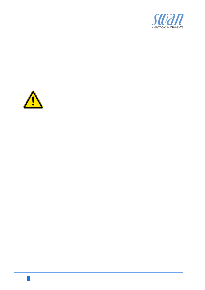
The sample flows via the sample inlet [D] and the flow regulating
valve [C] into the constant head [A]. Adjust the flow regulating valve
so that always a small part of the sample flows through the overflow
tube [M] into the waste. This adjustment ensures a sufficient sample flow through the flow cell [K]. First the sample flows into the
measuring chamber [K
and the sodium concentration of the sample is measured. From
there it flows into the measuring chamber [K2] where the pH electrode [F], the temperature sensor [H] and the reference electrode
[E] are installed and thereafter it flows via flow cell [K3] through the
sample outlet [L].
During on-line operation, the standard bottle holder [Q] is completely turned down, and the sample flows from the constant head [A]
into the reaction tube [B].
Due to the different level of the constant head and the flow cell, a
negative pressure is created in the reaction tube [B]. As a result, reagent saturated air is sucked into the reaction tube, raising the pH
of the sample to a value of 10.5, and forming a regular stream of air
bubbles [J].
The bubble stream is used to monitor the correct sample flow with
the bubble detector [I]. An inconsistent sample flow causes an interruption of the bubble formation and produces a system error.
] where the sodium electrode [G] is installed
1
10 A-96.250.211 / 200416
Page 13
AMI Sodium P
A
B
C
D
E
E
F
F
G
G
H
H
I
J
L
M
K
K
1
K
2
K
3
N
O
P
R
S
Q
Product Description
Fluidics
A-96.250.211 / 200416 11
A
Constant head
B
Reaction tube
C
Flow regulating valve
D
Sample inlet
E
Reference electrode
F
pH electrode
G
Sodium electrode
H
Temperature sensor
I
Bubble counter
J
Sample with air bubbles
K
Flow cell
L
Sample outlet
M
Overflow tube
N
Air inlet filter
O
Air tube to DIPA bottle
P
Tube with DIPA saturated air
Q
Standard bottle holder
R
Reagent bottle
S
Flow cell top view
Page 14

AMI Sodium P
Product Description
Second
Sample Stream
Sample
Sequencer
Grab Sample The standard bottle holder can also be used for a grab sample
Calibration A standard bottle is screwed in the standard bottle holder [Q] and
If required the AMI Sodium P can be equipped with the optional
second sample stream module. To install the 2nd sample stream
option a AMI Sodium P with 400 mm panel with is required.
If measurement of more than two sample streams is required, the
AMI Sodium P can be connected to a Sample Sequencer which allows to measure up to six sample streams.
measurement. Grab sample measurement see Grab Sample, p.
51.
turned upwards into the vertical position, thus switching the sample
flow from the constant head to the standard bottle. Constant pressure within the standard bottle is maintained by the pressure-equalizing tube inside the bottle.
1 liter standard is consumed in approx. 10 min. The sodium electrode must reach constant readings within this time to obtain an exact calibration.
For details, see Calibration, p. 42.
12 A-96.250.211 / 200416
Page 15

AMI Sodium P
Product Description
2.1. Instrument Specification
Power Supply Voltage:
Power consumption:
Electronics Aluminium with a protection degree of IP 66 / NEMA 4X
housing Ambient temperature:
Limit range of operation:
Storage and transport:
Humidity:
Display:
Sample
requirements
On-site The analyzer site must permit connections to:
requirements Sample inlet:
pH Value:
Ammonium concentration:
Flow rate:
Temperature:
Inlet pressure:
Outlet pressure:
NOTICE: No oil, no grease, no sand.
Sample outlet:
Max. Altitude:
100–240 VAC (± 10%)
50/60 Hz (± 5%)
or 24 VDC (± 10%)
max. 30 VA
-10 to +50 °C
-25 to +65 °C
-30 to +85 °C
10–90% rel., non condensing
backlit LCD, 75 x 45 mm
pH 7.0
< 10 ppm
min. 100 ml/min.
5–45 °C (41–113 °F)
0.3–3 bar (4 – 43 PSI)
pressure free
Tube 4 x 6 mm
1/2” hose nozzle for flexible tube diam.
20x15 mm
2000 m above sea level
A-96.250.211 / 200416 13
Page 16
AMI Sodium P
Exit Enter
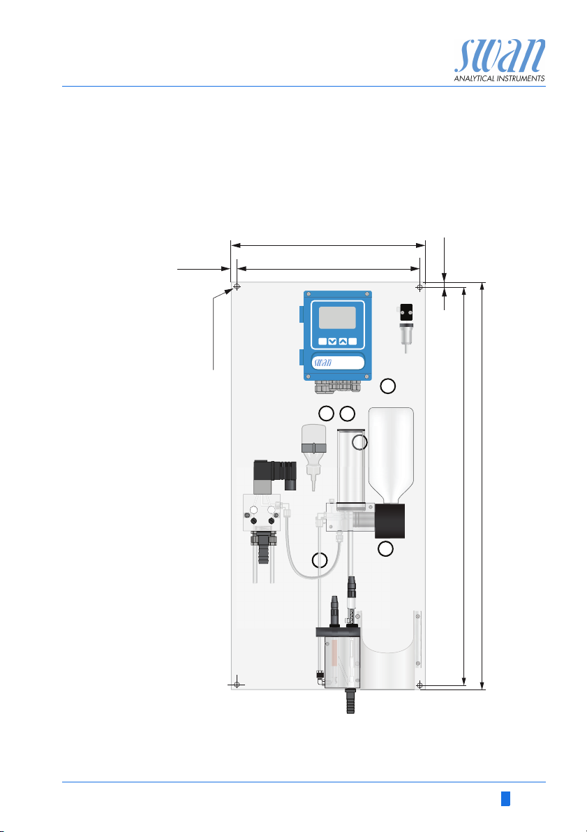
824 mm / 32
7
/
16
”
850 mm / 33½”
13 mm / ½”
280 mm / 11”
254 mm / 10”
13 mm / ½”
4 x dia. 10 mm
3
/
8
”
Product Description
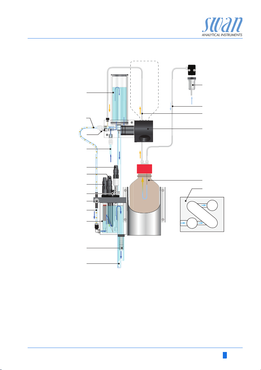
Dimensions: Panel:
Mounting hole distance:
Screws:
Weight:
280 x 850 x 200 mm
254 x 824 mm
8 mm diameter
9.0 kg / 19.85 lbs without sample water
14 A-96.250.211 / 200416
Page 17
AMI Sodium P
Exit Enter
824 mm / 32
7
/
16
”
850 mm / 33½”
13 mm / ½”
400 mm / 11”
374 mm / 10”
13 mm / ½”
4 x dia. 10 mm
3
/
8
”
Product Description
Dimensions
with 2nd
sample stream
Panel:
Mounting hole distance:
Screws:
Weight:
400 x 850 x 200 mm
374 x 824 mm
8 mm diameter
12.0 kg / 26.5 lbs without sample water
A-96.250.211 / 200416 15
Page 18
AMI Sodium P
A
Product Description
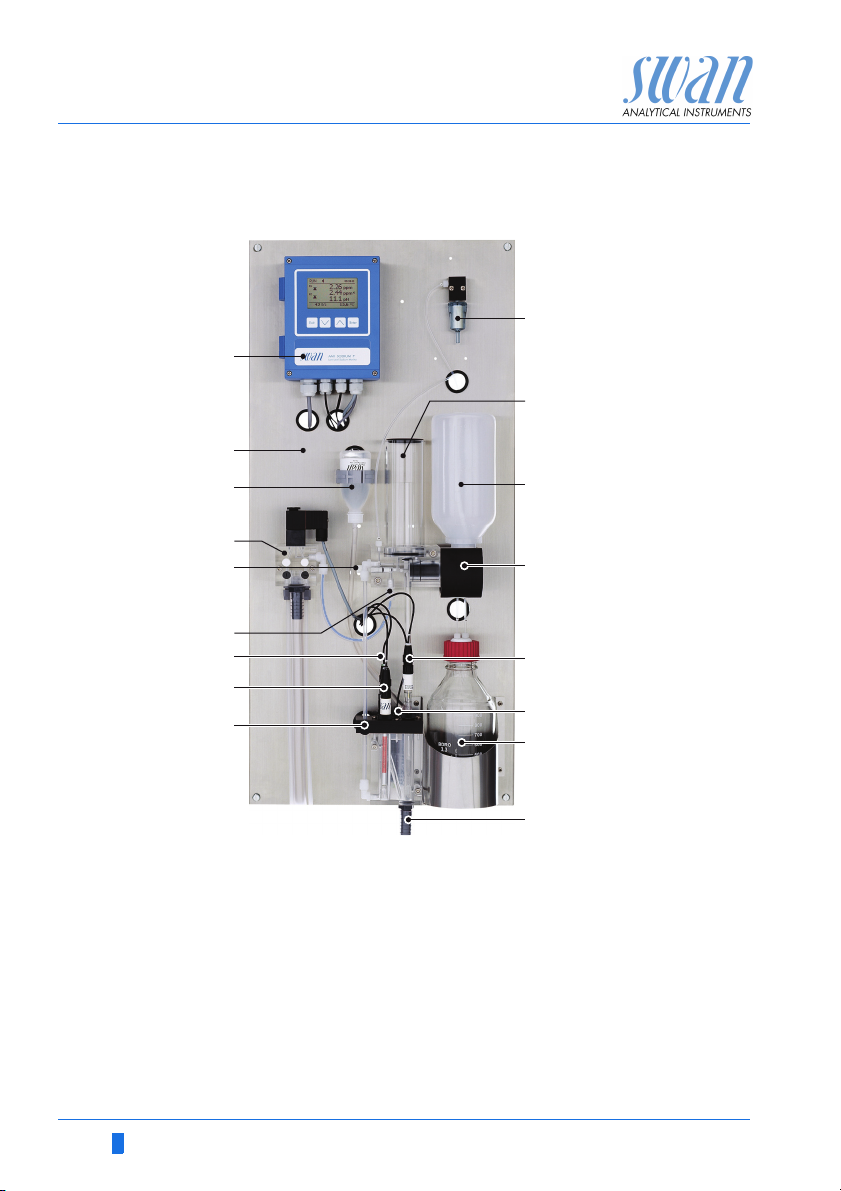
2.2. Instrument Overview
B
J
K
C
D
E
F
G
H
I
A
Transmitter
B
Panel
C
Reference electrolyte bottle
nd
sample stream (option)
D
2
Flow regulating valve
E
Sample inlet
F
pH electrode
G
Sodium electrode
H
Bubble detector
I
L
M
N
O
P
Q
J
Air filter
K
Constant head
L
Standard bottle/Grab sample
M
Standard bottle holder
N
Reference electrode
O
Temperature sensor
P
Reagent bottle
Q
Sample outlet
16 A-96.250.211 / 200416
Page 19
AMI Sodium P
Installation
3. Installation
3.1. Installation Check List
Check Instrument’s specification must conform to the National Electrical
Code, all state and local codes, and all plant codes and standards
for electrical equipment.
On site requirements
Installation Install the instrument in vertical position.
Electrodes Sodium electrode: Install the Sodium Electrode, p. 21.
Reagent and
filter connections
100 - 240 VAC ( 10%), 50/60 Hz ( 5%) or 24 VDC, isolated
(±10%) power outlet with ground connection and 30 VA
Sample line with min. 100 ml/min and 0.3–3.0 bar (4–43 psi)
Waste line with pressure free drain.
See Connecting Sample and Waste, p. 21.
Display should be at eye-level.
Connect the sample and waste line(s).
See Connecting Sample and Waste, p. 21
Etch the sodium electrode
Rinse it well and check for air bubbles inside the electrode.
Install the sodium electrode.
Connect cable S to the sodium electrode.
Reference electrode: Install the Reference Electrode, p. 23.
Install KCl bottle,
Check the ground joint diaphragm
Install the reference electrode.
Puncture the KCl bottle.
Connect cable R to the reference electrode.
pH electrode: Install the pH Electrode, p. 27.
Install the pH electrode.
Connect cable pH to the pH electrode
We recommend to use DIPA to operate the instrument. Use a
reagent bottle with either G45 thread (Schott) or a bottle from
Merck using a thread adapter. Close the bottle well to prevent the
formation of reagent vapors. For installation see Install Reagent
Bottle, p. 44.
Install the air filter.
A-96.250.211 / 200416 17
Page 20
AMI Sodium P
Installation
Electrical Wiring
Power-up Turn on the sample flow and wait until the measuring cell is com-
Instrument
Setup
Run-in period Let the instrument run continuously for 1 h.
Calibrate pH See pH Process Calibration, p. 43
Calibration
Sodium electrode
NOTICE: Do not switch on the Instrument until all electrical
connections are made.
Connect all external devices like limit switches, see Electrical Con-
nections, p. 22.
Connect power cord.
pletely filled.
Adjust the sample flow until the bubble stream is regular.
Switch on power. See Establish Sample Flow, p. 39
Program all parameters for external devices (interface, recorders,
etch.). Program all parameters for instrument operation (limits,
alarms, measuring interval).
Rinse the standard bottles well with deionized water. Prepare the
sodium standards directly in the graduated standard bottles using
a precision pipette. Make sure the concentrations are programmed
correctly. Perform a two point calibration.
See Calibration, p. 64
3.2. Mounting of Instrument Panel
The first part of this chapter describes the preparing and placing of
the instrument for use.
The instrument must only be installed by trained personnel.
Mount the instrument in vertical position.
For ease of operation mount it so that the display is at eye
level.
For the installation a kit containing the following installation
material is available:
– 4 Screws 8x60 mm
– 4 Dowels
– 4 Washers 8.4/24 mm
Mounting re-
quirements
The instrument is only intended for indoor installation.
For dimensions see Dimensions:, p. 14 or Dimensions with 2nd
sample stream, p. 15.
18 A-96.250.211 / 200416
Page 21
AMI Sodium P
Installation
3.3. Connect Sample and Waste
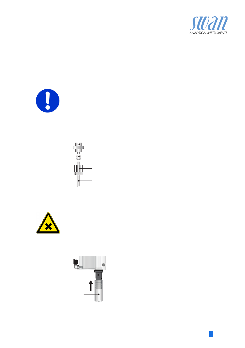
3.3.1 FEP Tube at Sample Inlet
Use plastic tube 4 x 6 mm to connect the sample line.
Mounting of
SERTO fitting
CAUTION
Damage of acrylic glass flow cell
Never screw steel fittings directly into the threads of the acrylic
glass.
Only use steel tubings with special fitting.
A
A
B
C
D
Screw connection
B
Compression ferrule
C
Knurled nut
D
Flexible tube
3.3.2 Sample Outlet
WARNING
Risk of water pollution
The drain of the Flow cell outlet contains Diisopropylamine
(DIPA)
At no means recirculate it into the water system.
ABHose nozzle
1/2” tube
A
B
Connect the 1/2” tube [B] to the hose nozzle [A] and place it into a
pressure free drain with sufficient capacity.
A-96.250.211 / 200416 19
Page 22
AMI Sodium P
A
B
C
D
E
Installation
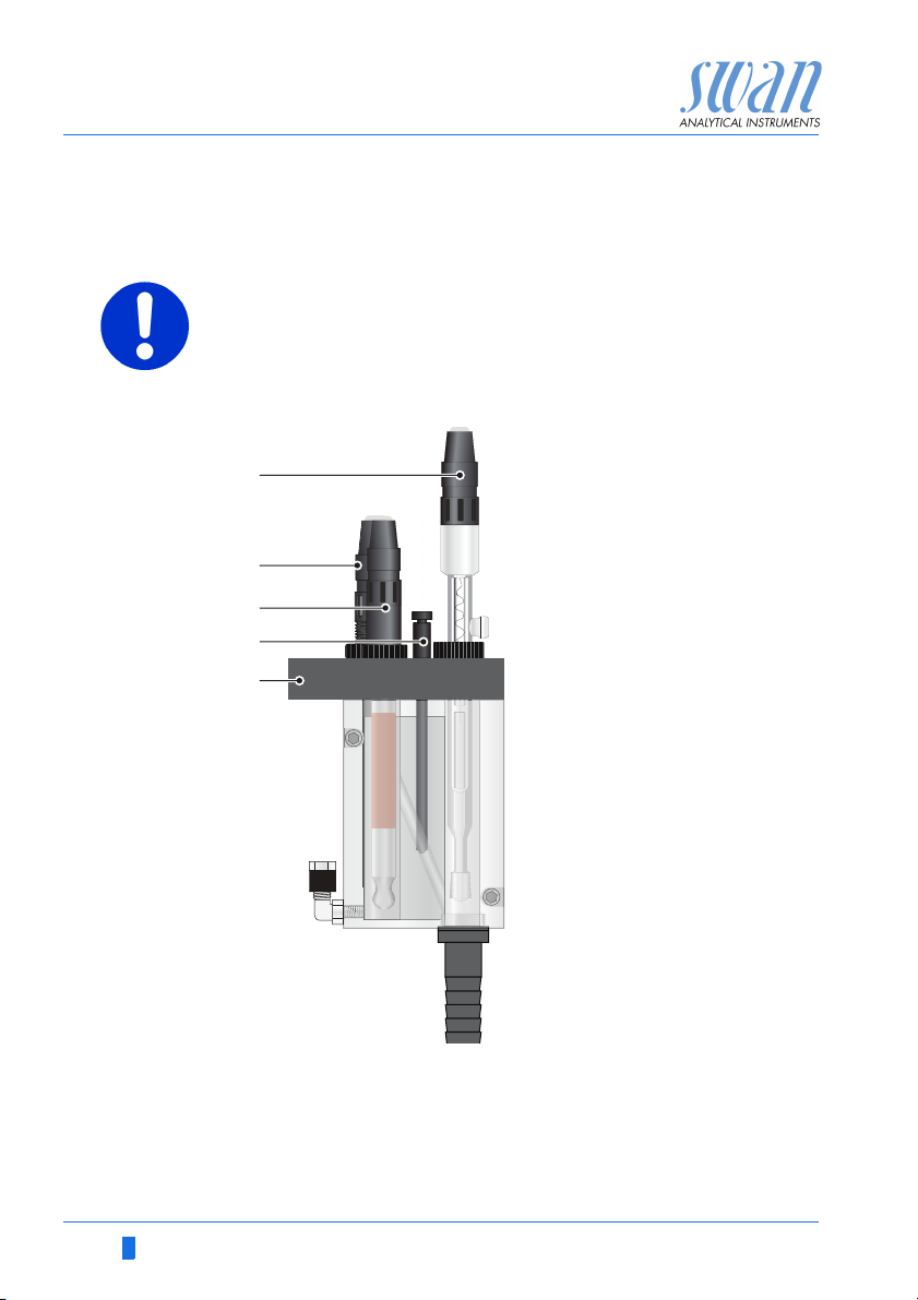
3.4. Install Sensors
CAUTION
The electrodes are made of glass and therefore very sensitive.
Handle with care.
Position of
sensors
A
Reference electrode, cable
marked with R
B
pH electrode, cable marked
with PH
C
Sodium electrode, cable
marked with S
D
Temperature sensor, cable
marked with T
E
Flow cell cover
Unpacking The electrodes are supplied separately and are installed into the
flow cell after mounting of the instrument panel. The electrodes are
protected with protective caps at their tips as well as on the electrical connectors.
Remove the connector caps from the connector only when the
electrode is mounted in the measuring cell.
20 A-96.250.211 / 200416
Page 23
AMI Sodium P
A
Installation
3.4.1 Install the Sodium Electrode
General Sodium electrodes are sensitive, electrochemical devices with a
very high internal impedance. To maintain correct operation make
sure that:
The electrode is delivered with protective caps on the sensing glass
bulb as well as on the electrical connector.
B
C
D
the sensing glass bulb stays clean.
no air bubbles are trapped in the glass bulb of the electrode.
the electrical connectors stay clean and dry.
E
F
G
H
A-96.250.211 / 200416 21
I
A
Sensor plug
B
Connector cap
C
Electrode shaft
D
Measuring chamber hole
E
Sensing glass bulb
F
Union screw
G
Washer
H
O-ring
I
Protective cap
Page 24

AMI Sodium P
Installation
Install the sodium electrode as follows:
1 Remove the protective cap [I] from the electrode with a careful
2 Etch the electrode, see Cleaning and etching, p. 54 and note
3 Rinse the electrode with demineralized water.
4 Slip the union nut [F], and washer [G] on the electrode shaft [C].
5 Wet the O-ring [H] and slip it carefully over the electrode shaft
6 Make sure no air bubbles are trapped in the sensing glass bulb
7 Insert the electrode through the measuring chamber hole [D]
8 Tighten the union screw [F] finger tight.
9 Remove the connector cap [B] from the electrode.
10 Screw the connector [A], of the cable marked with S, onto the
11 Connect the cable to the front end in the AMI Transmitter, see
turning and pulling movement.
the warning about handling of the chemicals.
[C].
[E]. Shake the electrode like a clinical thermometer with its tip
pointing downwards until the bubble is vanished.
into the measuring chamber and push down completely.
electrode.
Connection of Sensors, p. 43.
22 A-96.250.211 / 200416
Page 25
AMI Sodium P
A
B
C
Installation
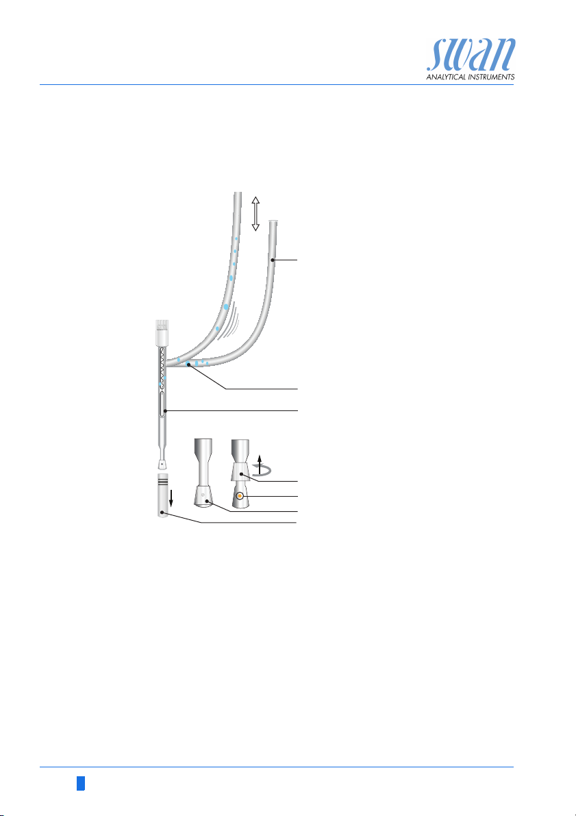
3.4.2 Install the Reference Electrode
General The SWAN reference electrode is a double junction Calomel / KCl
type electrode. The outer liquid junction is a liquid glass sleeve,
guaranteeing easy maintenance and long life time.
To maintain correct operation make sure that:
the ground joint diaphragm stays clean and a KCl flow of
about 1ml/day is maintained.
no air bubbles are trapped in the electrode and in the tube to
the KCl reservoir.
the electrical connectors stay clean and dry.
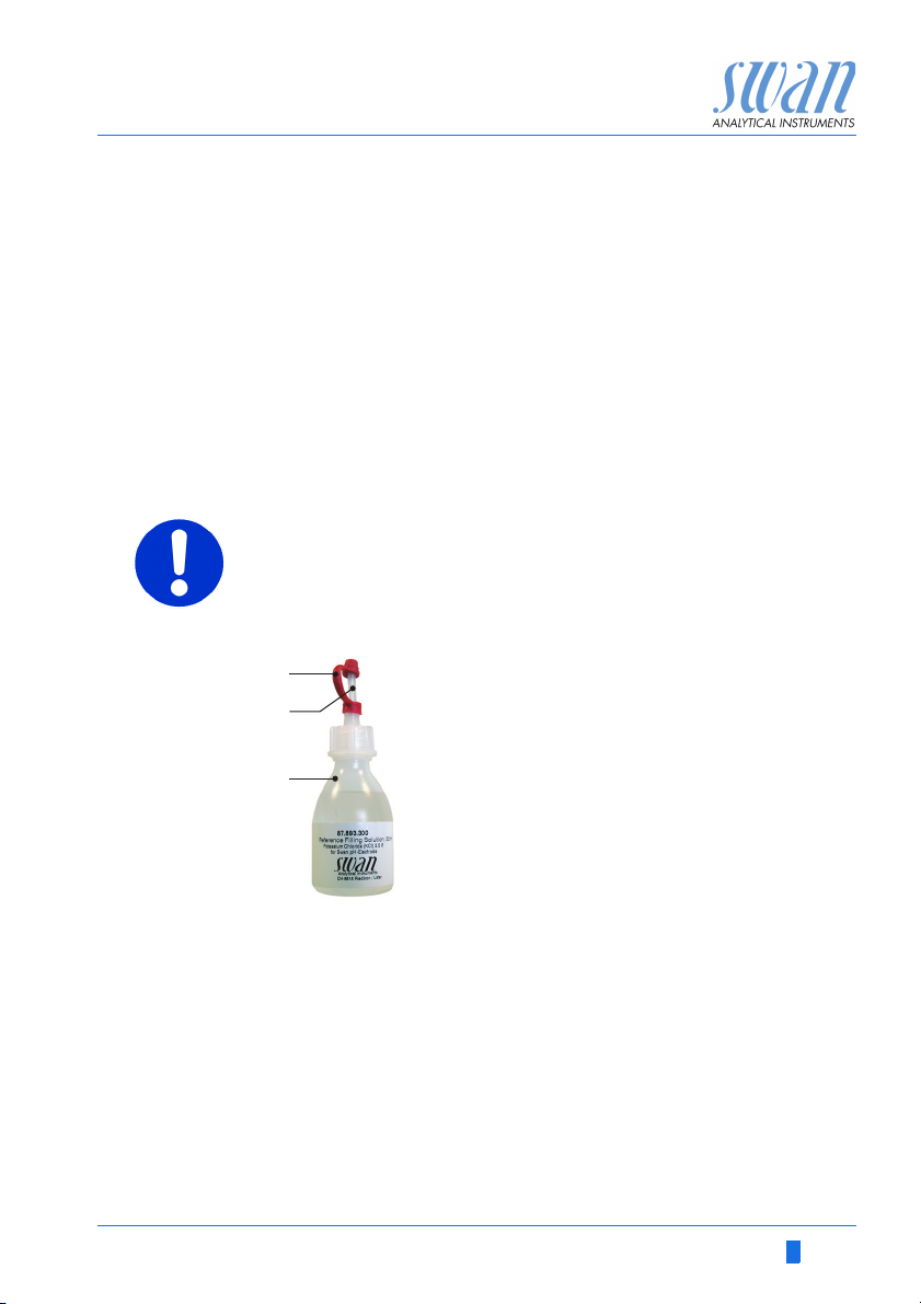
CAUTION
KCL is corrosive
Do not let electrolyte drop on the measuring cell.
Prepare the
KCl Bottle
1 Remove the seal cap [A] from the dosing tip [B].
2 Cut off the upper sealed part of the dosing tip.
A-96.250.211 / 200416 23
A
Seal cap
B
Dosing tip
C
KCl bottle
Page 26
AMI Sodium P
A
B
C
D
E
F
G
Installation
Prepare the
reference
electrode
After longer storage of the reference electrode, the diaphragm may
be clogged wit salt deposits of KCl. Therefore it is recommended to
open and clean the diaphragm before installing the reference electrode.
A
KCl supply tube
B
Trapped air bubble
C
Reference electrode
D
Ring-shaped sleeve opened
E
Electrolyte outlet hole
F
Ring-shaped sleeve closed
G
Protective cap
To clean the reference electrode proceed as follows:
1 Remove the protective cap [G] from the ground joint diaphragm
with a careful turning and pulling movement.
2 Hold the reference electrode with the ground joint diaphragm
pointing downwards.
3 Slightly lift the ring-shaped sleeve of the ground-joint diaphragm
and allow a little electrolyte to flow out into a tissue.
4 Rinse the electrode tip well with deionized water.
5 Push the ring-shaped sleeve carefully over the ground-joint dia-
phragm.
6 While holding the electrode tip pointing downwards pull the KCI
supply tube several times so that the air bubbles can escape
upwards.
24 A-96.250.211 / 200416
Page 27
AMI Sodium P
E
A
D
C
B
F
H
G
H
I
J
K
L
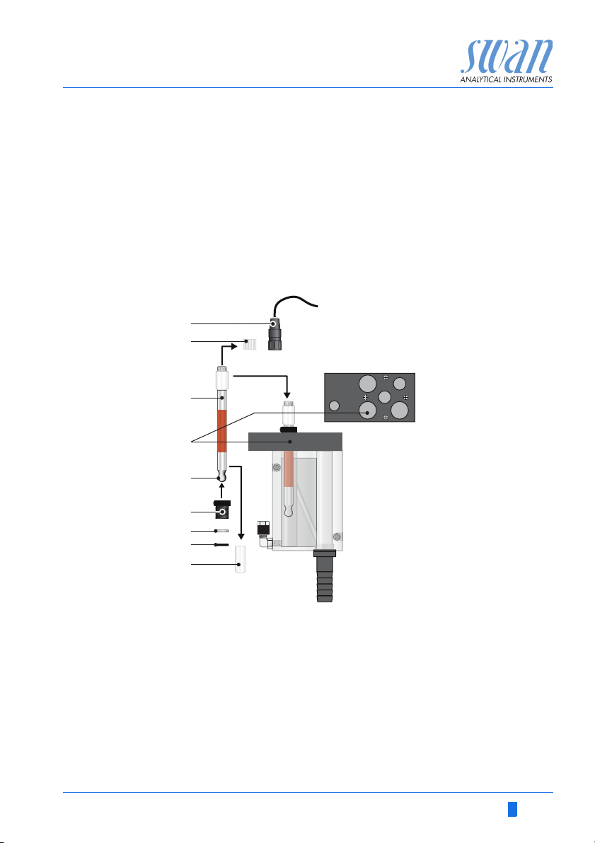
Installation
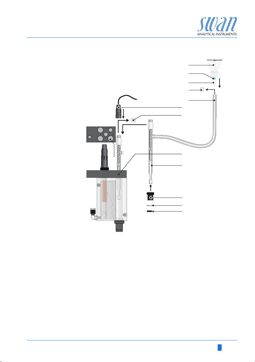
Install the
reference
electrode
A
KCl Bottle
B
C
D
E
F
A-96.250.211 / 200416 25
Install the reference electrode as follows:
1 Remove the stopper [D] from the KCl supply tube [E].
2
3 Fix the KCl bottle upside down in the holder on the panel.
4 Puncture the bottle bottom to allow pressure equilibration.
Trapped air bubble
Dosing tip
Stopper
KCl supply tube
Sensor plug
Connect the KCl supply tube to the dosing tip [C] of the KCl bottle.
G
Connector cap
H
Reference chamber hole
I
Electrode shaft
J
Union screw
K
Washer
L
O-ring
Page 28

AMI Sodium P
Installation
5 Knock against the KCl bottle to remove trapped air bubbles [B]
6 Slip the union screw [J], and washer [K] on the electrode shaft
7
8 Insert the electrode through the hole [H] into the reference
9 Tighten the union screw [J] finger tight.
10 Remove the connector cap [G] from the electrode.
11 Screw the connector [F], of the cable marked with R, onto the
12 Connect the cable to the front end in the AMI Transmitter, see
in the dosing tip.
NOTICE: Air bubbles trapped in the dosing tip of the KCl bottle
may stop the KCl flow to the reference electrode, which results
in wrong measuring values.
[I].
Wet the O-ring [L] and slip it carefully over the electrode shaft [I].
chamber and push it down until the ground joint diaphragm is
about 0.5 cm above the bottom.
electrode.
Connection of Sensors, p. 43.
26 A-96.250.211 / 200416
Page 29

AMI Sodium P
A
B
C
D
E
F
G
H
Installation
3.4.3 Install the pH Electrode
A
Connector cap
B
Sensor plug
C
Sensor shaft
D
Protective cap
E
Union screw
F
Washer
G
O-ring
H
pH sensor hole
1 Carefully remove the protective cap [D] from the electrode tip.
Turn it clockwise only.
2 Rinse the electrode tip with clean water.
3 Slip union screw [E], and washer [F] on the electrode shaft [C].
4 Wet the O-ring [G] and slip it carefully over the electrode shaft.
5 Insert the electrode through the hole [H] in into the flow cell.
6 Tighten the union screw [E] hand-tight.
7 Remove the connector cap [A].
8 Screw the connector [B], of the cable marked with pH, onto the
pH electrode.
9 Keep the protective caps on a secure place for later use.
10 Connect the cable to the front end in the AMI Transmitter, see
Connection of Sensors, p. 43.
A-96.250.211 / 200416 27
Page 30
AMI Sodium P
A
B
C
D
E
Installation
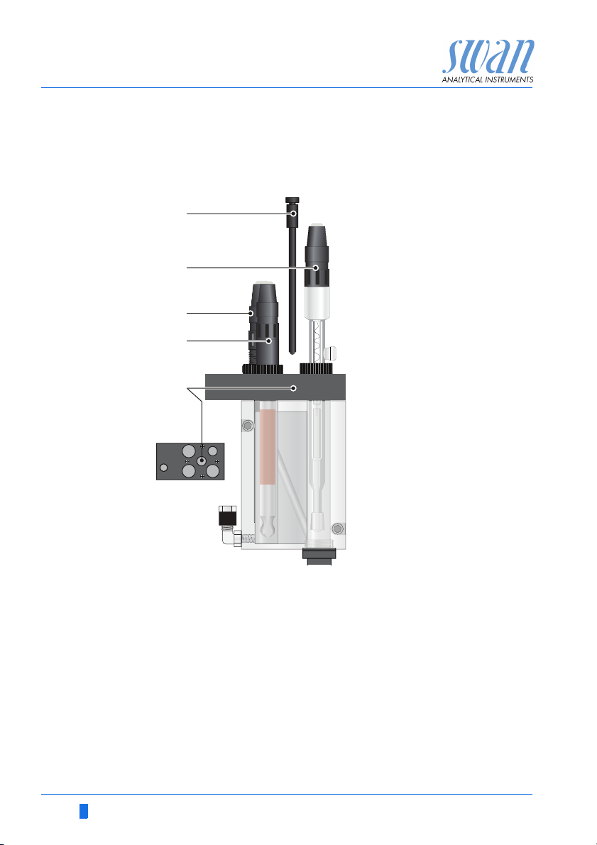
3.4.4 Install the Temperature Sensor
The temperature sensor is fixed to the panel with an adhesive tape
and already connected to the front end PCB in the AMI transmitter.
A
Temperature sensor
B
Reference sensor
C
pH sensor
D
Sodium sensor
E
Temperature sensor
hole
To install the temperature sensor proceed as follows:
1 Remove the temperature sensor [A] from the panel.
2 Insert the temperature sensor through the hole [E] into the flow
cell.
3 Push it into the hole as far as it will go.
3.4.5 Install reagent bottle
The DIPA bottle will be installed only shortly before commissioning,
see chapter 4, Install Reagent Bottle, p. 44.
28 A-96.250.211 / 200416
Page 31

AMI Sodium P
A
Installation
3.5. Install 2nd Sample Stream (Option)
B
C
D
E
F
G
H
I
J
A
Constant head support
B
Blind plug
nd
sample stream option
C
A-96.250.211 / 200416 29
2
with solenoid valve
Flow regulating valves
D
Fixing screws
E
To install the optional 2nd sample stream, proceed as follows:
1 Stop the sample flow at the main tap.
2 Switch off the instrument.
3 Replace the flow regulating valve from the constant head sup-
port [A] with the blind plug [B].
4 Remove the existing sample inlet tube [J] from the constant
head support inlet.
nd
5 Screw the 2
screws [E] on the panel.
sample stream option (C) with the two fixing
F
Sample stream 1
G
Hose nozzle for drain funnel
H
Sample stream 2
I
Connection tube
J
Existing sample inlet tube
Page 32

AMI Sodium P
BA
Installation
6 Install the connection tube [I] between the 2nd sample stream
7 Connect sample inlet 1 (F) and sample inlet 2 (H) to the corre-
8 Connect a 1/2” tube to the hose nozzle [G] and put it into a
9 Connect the solenoid valve cable to the transmitter, see Con-
3.5.1 Connect the solenoid valve
Use one of the PG7 cable glands to feed the cable of the solenoid
valve into the AMI transmitter housing.
outlet and the constant head support inlet.
sponding inlets at the 2
pressure free drain.
nect the solenoid valve, p. 30.
WARNING
Electrical shock hazard!
Before opening the AMI Transmitter switch power off.
nd
sample stream.
1 Remove the plug [A] from the cable gland [B.
2 Open the transmitter housing.
3 Feed the cable of the solenoid valve through the cable gland (B)
into the AMI transmitter housing.
4 Connect the wires to the terminals in the AMI transmitter
according to the Connection Diagram, p. 35.
In the connection diagram labelled as “Selector”.
5 Close the transmitter housing and start the Instrument.
30 A-96.250.211 / 200416
Page 33

AMI Sodium P
5.1.4
Temperature HT5K
Sensors
Flow B/ s
Sensor type Sodium
Channel switch None
Standards
5.1.4
Temperature HT5K
Sensors
Flow B/ s
Sensor type Sodium
Channel switch Auto
Standards
No
Save?
Yes
4.1.31
Hold after cal. 300 sec
Sensors
Filter Time Const. 180 sec
Interval 15 Min
Installation
3.5.2 Firmware settings for 2nd sample stream option
After the 2nd sample stream option is installed and connected, set
the firmware according to your requirements.
With 2
in the following 4 different modes.
1 Navigate to menu <Installation /
Sensors>.
2 Navigate to <Channel switch> with
the[ ] or[ ] key.
3 Press [Enter].
4 Set <Channel switch> to the re-
quired mode with the [ ] key.
5 Confirm with [Enter].
6 Press [Exit], choose <Save> “Yes”
Confirm with [Enter].
nd
sample stream option the AMI Sodium P can be operated
None
Auto
User defined
Fieldbus
None The switch over between the channels is disabled, channel 1 is ac-
A-96.250.211 / 200416 31
tive.
Auto Only visible if <Channel switch> in menu 5.1.4 is set to <Auto>.
The switch over between the two sample streams is controlled by
the AMI Transmitter according to the programmed measuring interval in the menu <Operation>.
1 Navigate to menu <Operation/
Sensors>.
2 Choose <Interval> with the [ ]
or[ ] key.
3 Press [Enter] and set the interval
according your requirements between 15 and 120 Min.
Page 34

AMI Sodium P
4.1.32
Hold after cal. 300 sec
Sensors
Filter Time Const. 180 sec
Channer selection Dig. Input
Channel 2
Channel selection
Dig. Input
Channel 1
Installation
User defined Only visible if <Channel switch> in menu 5.1.4 is set to
<User defined>.
Choose either Channel 1, Channel 2 or Digital Input (Dig. Input).
1 Navigate to menu <Operation/
Sensors>.
2 Choose <Channel selection> with
the [ ] or[ ] key.
3 Press [Enter] to select required
function.
Channel 1: Only channel 1 is measured.
Channel 2: Only channel 2 is measured.
Dig. Input: The channel can be selected via input. The function
Input in menu 5.3.4 is set to <Active = no>.
Fieldbus The switch over between the two sample streams is controlled by
the Profibus.
3.6. AMI Sodium P connected to a Sample Sequencer
If more than two sample streams are required, an AMI Sample Sequencer can be connected to the AMI Sodium P which allows to
measure up to six sample streams. The electrical connection is described in the Manual of the AMI Sample Sequencer.
NOTICE: If the AMI Sodium P is already equipped with a 2nd
Sample Stream option, it is not possible to operate it with an
AMI Sample Sequencer. Before connecting an AMI Sample
Sequencer remove the 2
32 A-96.250.211 / 200416
nd
Sample Stream option.
Page 35

AMI Sodium P
Installation
3.7. Electrical Connections
Cable
thicknesses
In order to comply with IP66, use the following cable thicknesses
WARNING
Risk of electrical shock.
Do not perform any work on electrical components if the transmitter is switched on. Failure to follow safety instructions could
result in serious injury or death.
Always turn off AC power before manipulating electric parts.
Grounding requirements: Only operate the instrument from
an power outlet which has a ground connection.
Make sure the power specification of the instrument corre-
sponds to the power on site.
ABC
PG 11 cable gland: cable Ø
A
B
PG 7 cable gland: cable Ø
C
PG 9 cable gland: cable Ø
5–10 mm
outer
3–6.5 mm
outer
4–8 mm
outer
NOTICE: Protect unused cable glands
Wire For Power and Relays: Use max. 1.5 mm
stranded wire with end sleeves.
For Signal Outputs and Input: Use 0.25 mm
2
/ AWG 14
2
/ AWG 23
stranded wire with end sleeves.
A-96.250.211 / 200416 33
Page 36

AMI Sodium P
Installation
WARNING
External Voltage.
External supplied devices connected to relay 1 or 2 or to the
alarm relay can cause electrical shocks
Make sure that the devices connected to the following con-
tacts are disconnected from the power before resuming installation.
–relay 1
–relay 2
– alarm relay
WARNING
To prevent from electrical shock, do not connect the instrument
to the power unless the ground wire (PE) is connected.
Do not connect unless specifically instructed to do so.
WARNING
The mains of the AMI Transmitter must be secured by a main
switch and appropriate fuse or circuit breaker.
34 A-96.250.211 / 200416
Page 37

AMI Sodium P
Installation
3.7.1 Connection Diagram
CAUTION
Use only the terminals shown in this diagram, and only for the
mentioned purpose. Use of any other terminals will cause short
circuits with possible corresponding consequences to material
and personnel.
A-96.250.211 / 200416 35
Page 38

AMI Sodium P
A
B
C
D
Installation
WARNING
Risk of electrical shock
Do not perform any work on electrical components if the transmitter is switched on. Failure to follow safety instructions could
result in serious injury or death.
Always turn off AC power before manipulating electric parts.
Installation and maintenance of electrical parts must be per-
formed by professionals.
A
Power supply connector
B
Neutral conductor, Terminal 2
C
Phase conductor, Terminal 1
D
Protective earth PE
NOTICE: The protective earth wire (Ground) has to be
connected to the grounding terminal.
Installation
requirements
The installation must meet the following requirements.
Fuse 1.6 AT
Mains cable to comply with standards IEC 60227 or IEC
60245; flammable rating FV1
Mains equipped with an external switch or circuit-breaker
– near the instrument
– easily accessible to the operator
– marked as interrupter for AMI Sodium P
36 A-96.250.211 / 200416
Page 39

AMI Sodium P
10
12
11
0V
Installation
3.8. Relay Contacts
3.8.1 Input
Terminals 16/42
For programming see Program list and explanation, 5.3.4, p. 98.
3.8.2 Alarm Relay
Alarm output for system errors.
Error codes see Error List, p. 73.
Terminals Description Relay connection
1)
NC
Normally
Closed
10/11 Active (opened) during normal
NOTICE: Use only potential-free (dry) contacts.
The total resistance (sum of cable resistance and resistance of
the relay contact) must be less than 50 Ω.
NOTICE: Max. load 1 A / 250 VAC
NOTICE: With certain alarms and certain settings of the AMI
transmitter the alarm relay does not switch. The error, however,
is shown on the display.
operation.
Inactive (closed) on error and
loss of power.
1)
0V
11
10
12
NO
Normally
Open
12/11 Active (closed) during normal
operation.
Inactive (opened) on error and
loss of power.
1) usual use
A-96.250.211 / 200416 37
Page 40

AMI Sodium P
6
0V
7
6
0V
7
A
B
Installation
3.8.3 Relay 1 and 2
Relay 1 and 2 can be configured as normally open or as normally
closed. Standard for both relays is normally open. To configure a
Relay as normally closed, set the jumper in the upper position.
NOTICE: Max. load 1 A/250 VAC
NOTICE: Some error codes and the instrument status may
influence the status of the relays described below.
Relay
config. Terminals
Normally
Open
Normally
Closed
6/7: Relay 1
8/9: Relay 2
6/7: Relay 1
8/9: Relay 2
Jumper
pos. Description Relay configuration
Inactive (opened) during
normal operation and
loss of power.
Active (closed) when a
programmed function is
executed.
Inactive (closed) during
normal operation and
loss of power.
Active (opened) when a
programmed function is
executed.
ABJumper set as normally open (standard setting)
Jumper set as normally closed
For programming see 5.3.2 and 5.3.3, p. 93, menu Installation.
38 A-96.250.211 / 200416
Page 41

AMI Sodium P
A
BC
DE
AB
C
Installation
CAUTION
Risk of damage of the relays in the AMI Transmitter due to
heavy inductive load.
Heavy inductive or directly controlled loads (solenoid valves,
dosing pumps) may destroy the relay contacts.
To switch inductive loads > 0.1 A use an AMI relay box avail-
able as an option or suitable external power relays.
Inductive load Small inductive loads (max 0.1A) as for example the coil of a power
Resistive load Resistive loads (max. 1A) and control signals for PLC, impulse
Actuators Actuators, like motor valves, are using both relays: One relay con-
relay can be switched directly. To avoid noise voltage in the
AMI Transmitter it is mandatory to connect a snubber circuit in parallel to the load.
A snubber circuit is not necessary if an AMI relaybox is used.
A
AC or DC power supply
B
AMI Transmitter
C
External power relay
D
Snubber
E
Power relay coil
pumps and so on can be connected without further measures
A
AMI Transmitter
B
PLC or controlled pulse pump
C
Logic
tact is used for opening, the other for closing the valve, i.e. with the
2 relay contacts available, only one motor valve can be controlled.
Motors with loads bigger than 0.1A must be controlled via external
power relays or an AMI relay box.
A
A
BC
AC or DC power supply
B
AMI Transmitter
C
Actuator
A-96.250.211 / 200416 39
M
Page 42

AMI Sodium P
Installation
3.9. Signal Outputs
3.9.1 Signal Output 1 and 2 (current outputs)
Signal output 1: Terminals 14 (+) and 13 (-)
Signal output 2: Terminals 15 (+) and 13 (-)
For programming see Program Overview, p. 51, Menu Installation
3.10. Interface Options
NOTICE: Max. burden 510
If signals are sent to two different receivers, use signal isolator
(loop isolator).
A
AMI Transmitter
A
B
Slot for interfaces
C
Frontend PCB
D
Screw terminals
B
C
D
The slot for interfaces can be used to expand the functionality of
the AMI instrument with either:
an additional signal output
a Profbus or Modbus connection
an USB Interface
40 A-96.250.211 / 200416
Page 43

AMI Sodium P
Installation
3.10.1 Signal Output 3
Terminal 38 (+) and 37 (-).
Requires the additional board for the third signal output 0/4 – 20 mA
PCB. The third signal output can be operated as current source or
current sink (switchable via switch [A]). For detailed information see
the corresponding installation instruction.
Third signal output 0/4–20 mA PCB
A Operating mode selector switch
NOTICE: Max. burden 510
A
.
A-96.250.211 / 200416 41
Page 44

AMI Sodium P
ON
OFF
A
Installation
3.10.2 Profibus, Modbus Interface
Terminal 37 PB, Terminal 38 PA
To connect several instruments by means of a network or to config-
ure a PROFIBUS DP or a MODBUS connection, consult the PROFIBUS/MODBUS manual. Use appropriate network cable.
Profibus, Modbus Interface PCB (RS 485)
A On - OFF switch
NOTICE: The switch must be ON, if only one instrument is
installed, or on the last instrument in the bus.
3.10.3 USB Interface
The USB Interface is used to store Logger data and for Firmware
up load. For detailed information see the corresponding installation
instruction.
USB Interface
42 A-96.250.211 / 200416
Page 45

AMI Sodium P
A
B
C
D
Installation
3.11. Connection of Sensors
Front-end board
A
B
C
D
Temperature sensor cable marked with T, Terminal 19 / 20
pH electrode cable marked with pH
Reference electrode cable marked with R
Sodium electrode cable marked with S
A-96.250.211 / 200416 43
Page 46

AMI Sodium P
A
B
C
E
F
D
H
G
Instrument Setup
4. Instrument Setup
4.1. Install Reagent Bottle
CAUTION
Formation of reagent vapor
To prevent formation of reagent vapors:
close the reagent bottle firmly
check the EPDM seal regularly
install air tubes and filter properly
A
Screw cover G 45
B
Tube 1 from air filter
C
Tube 2 to reaction tube
D
Tube holder
E
EPDM seal
F
Air inlet tube
G
Reagent bottle
H
Bottle holder
NOTICE: Operate the instrument only with Diisopropylamine.
The Tubes are already installed into the tube holder [D] and the
EPDM seal [E] seats on the bottom of the tube holder. To install the
DIPA bottle proceed as follows:
1 Put the DIPA bottle [G] into the bottle holder [H]
2 Put the tube holder onto the DIPA bottle
3 Screw the screw cover [A] onto the DIPA bottle and tighten it
firmly.
4 Screw the tube fitting of tube 1 [B] into the tube holder [D], so
that it is connected to the air inlet tube.
5 Screw the tube fitting of tube 2 [C] into the tube holder [D], so
that it is connected to the DIPA vapor outlet.
44 A-96.250.211 / 200416
Page 47

AMI Sodium P
AB C D
Instrument Setup
4.2. Establish Sample Flow
A
Flow regulating valve
B
Sample inlet
C
Constant head
D
Bottle holder
WARNING
Risk of water pollution
The drain of the Flow cell outlet contains Diisopropylamine
(DIPA)
At no means recirculate it into the water system.
1 Swing down the bottle holder [D] as far as it will go.
2 Open the flow regulating valve [A].
3 Adjust the sample flow so that a small part of the sample over-
flows into the waste.
4 Check tubing connections and flow cell for leaks and repair if
necessary.
A-96.250.211 / 200416 45
Page 48

AMI Sodium P
3.3
Simulation
Calibration
Maintenance
Set Time 01.06.04 16:30:00
Cleaning
Service
3.3.1
Simulation
Relay 1 open/closed
Relay 2 open/closed
Signal Output 1 x mA
Signal Output 2 x mA
Alarm Relay open/closed
Instrument Setup
4.3. Switch on Power
First, the instrument performs a self test, displays the firmware version and then starts normal operation.
1 Let the instrument run continuously for 1 hour with sample.
4.4. Programming
Program all parameters for external devices (interface, recorders,
etc.) Program all parameters for instrument operation (limits,
alarms). For explanations, see Program List and Explanations, p.
81
4.5. Check Outputs and Relays
Terminal designations see Connection Diagram, p. 35
Check signal outputs and relay function by means of the connected
device or a multimeter.
Enter
4.6. Perform a calibration
1 Prepare the standards, see Prepare Standard, p. 64
2 Calibrate the pH sensor, see pH Process Calibration, p. 64
3 Calibrate the sodium electrode, see Standard Sodium 1-Point-
Calibration, p. 65.
46 A-96.250.211 / 200416
Page 49

AMI Sodium P
Exit
Enter
BCDA
25.4°C
RUN
10.84 pH
14:10:45
R1
0.42 ppb
R2
1
Installation
Operation
Diagnostics
Messages
Maintenance
Main Menu
Enter
Exit
Operation
5. Operation
5.1. Keys, Display
Keys
A to exit a menu or command (rejecting any changes) to move
B to move DOWN in a menu list and to decrease digits
C to move UP in a menu list and to increase digits
D to open a selected sub-menu to accept an entry
back to the previous menu level
Program
Access, Exit
A-96.250.211 / 200416 47
Page 50

AMI Sodium P
RUN
15:20:18
R1
R2
22.1°C
10.88 pH
ppm
16.8
ppm
21.5
AB C
E
F
G
H
D
Operation
Display
A RUN normal operation
B ERROR Error
C Transmitter control via Profibus
D Time
E
F Sample Temperature
G pH Value in flow cell
H Relay Status
HOLD input closed or cal delay: Instrument on hold (shows
status of signal outputs).
OFF input closed: Control/limit is interrupted (shows status
of signal outputs).
Fatal Error
Process Values:
2 channel operation: the active channel is flushed
measurement of active channel
1 channel operation: In 1 channel operation no symbols are displayed.
Relay status, symbols
upper/lower limit not yet reached
upper/lower limit reached
control upw./downw. no action
control upw./downw. active, dark bar indicates control intensity
motor valve closed
motor valve: open, dark bar indicates approx. position
timer
48 A-96.250.211 / 200416
timer: timing active (hand rotating)
Page 51

AMI Sodium P
1
Messages
Operation
Maintenance
Diagnostics
Main Menu
Installation
1.1
Pending Errors
Messages
Message List
2.1
Interface
I/O State
Sample
Identification
Sensors
Diagnostics
3.1
Calibration
Simulation
Maintenance
Set Time 23.09.06 16:30:00
Service
4.1
Logger
Relay Contacts
Sensors
Operation
5.1
Interface
Miscellaneous
Relay Contacts
Sensors
Signal Outputs
Installation
Operation
5.2. Software Structure
Menu Messages 1
Reveals pending errors as well as an event history
(time and state of events that have occurred at an
earlier point of time).
It contains user relevant data.
Menu Diagnostics 2
Provides user relevant instrument and sample data.
A-96.250.211 / 200416 49
Menu Maintenance 3
For instrument calibration, relay and signal output
simulation, and to set the instrument time.
It is used by the service personnel.
Menu Operation 4
User relevant parameters that might need to be
modified during daily routine. Normally password
protected and used by the process-operator.
Subset of menu 5 - Installation, but process-related.
Menu Installation 5
For initial instrument set up by SWAN authorized
person, to set all instrument parameters. Can be
protected by means of password.
Page 52

AMI Sodium P
5.1.2
Sensors
Sensor type FOME
Temperature NT5K
Standards
Disinf. Free chlorine
4.4.1
Logger
Log interval 30 min
Clear logger no
4.1.3
Logger
Clear logger no
Log interval 30min
1 Hour
Interval.
5 min
30 min
10 min
4.1.3
Logger
Log interval 10 min
Clear logger no
4.1.3
Logger
Log interval
Clear logger no
No
Save ?
Yes
5.3.1.1.1
Alarm High 5.00 ppm
Total chlorine 1
Alarm Low 0.00 ppm
Hysteresis 1.00 ppm
Delay 5 Sec
5.3.1.1.1
Total chlorine 1
Alarm Low 0.00 ppm
Hysteresis 1.00 ppm
Delay 5 Sec
Alarm High 2.00 ppm
Operation
5.3. Changing Parameters and Values
Changing
parameters
The following example shows how to change the logger interval:
1 Select the parameter you want to
change.
2 Press [Enter]
3 Press [ ] or [ ] key to
highlight the required parameter.
4 Press [Enter] to confirm the selec-
tion or [Exit] to keep the previous
parameter).
The selected parameter is
highlighted but not saved yet.
5 Press [Exit].
Yes is highlighted.
6 Press [Enter] to save the new pa-
rameter.
The system reboots, the new
parameter is set.
Changing
values
1 Select the value you want to
change.
2 Press [Enter].
3 Set required value with [ ] or
[] key.
4 Press [Enter] to confirm the new
value.
5 Press [Exit].
Yes is highlighted.
50 A-96.250.211 / 200416
6 Press [Enter] to save the new val-
ue.
Page 53

AMI Sodium P
Operation
5.4. Grab Sample
To perform a grab sample measurement proceed as follows:
1 Rinse a standard bottle well and fill it with grab sample.
2 Screw the grab sample bottle into the standard bottle holder
Do not use closed bottles
and swing it upwards.
This stops the sample flow from the constant head and
allows the grab sample to flow through the flow cell.
3 Press the [ ] key.
GRAB appears on the left side of the upper status line and
the instrument is measuring the grab sample now.
NOTICE: The measuring value of the grab sample will not be
saved in the transmitter. Wait until the measuring value is stable
and then write it down for later use.
4 After the grab sample bottle is empty, swing the bottle holder
down and unscrew the grab sample bottle.
5 Press the [ ] key again.
HOLD appears in the display (= cal delay). After the delay
time is over, the instrument goes back to the normal
operating mode.
A-96.250.211 / 200416 51
Page 54

AMI Sodium P
Maintenance
6. Maintenance
6.1. Maintenance Schedule
Check for regular bubble formation.
Weekly or
every 2 weeks
Monthly
Yea rly
If necessary
Check level of reagent bottle and replace it if necessary.
Etch sodium electrode with SWAN’s etching solution.
Perform a one-point calibration.
Check sealing of reagent bottle, replace if necessary.
Check level of KCl reservoir. If necessary refill bottle.
Etch sodium electrode in SWAN’s etching solution.
Make a two-point calibration.
Make a pH measurement and correct value if necessary.
Replace sodium electrode see Maintenance of Sodium
Electrode, p. 53.
Replace reference electrode, see Maintenance of Ref-
erence Electrode, p. 55.
Replace pH sensor, see Maintenance of pH Sensor, p.
56.
If necessary, remove deposited iron in the system by
washing in soft detergent and by using rust remover.
If covered heavily with iron, replace reaction tube.
Replace the air filter.
WARNING
Stop operation before maintenance.
Stop sample flow.
Shut off power of the instrument.
6.2. Stop of Operation for Maintenance
1 Stop sample flow.
2 Shut off power of the instrument.
3 Empty the constant head and the flow cell completely.
52 A-96.250.211 / 200416
Page 55

AMI Sodium P
A
B
D
C
E
Maintenance
6.3. Maintenance of Sodium Electrode
Sodium electrodes are sensitive electrochemical devices with very
high internal impedance. To maintain correct operation, make sure
that
the sensing glass bulb stays clean
no air bubbles are trapped between glass bulb and glass tube
the electrical connectors stay absolutely clean and dry.
A
Sensor plug
B
Connector cap
C
Union screw
D
Washer
E
O-ring
Remove the
sodium
electrode
A-96.250.211 / 200416 53
1 Unscrew and remove the sensor plug [A].
Prevent the connector from getting wet.
2 Put on the connector cap [B] onto the sensor.
3 Completely unscrew the union screw [C] from the threaded
hole.
4 Remove the electrode together with the union screw, washer
and O-ring from the measuring cell.
5 Slip the O-ring carefully over the measuring bulb and remove
both nut and washer.
Page 56

AMI Sodium P
Maintenance
Mix the etching
solution
Cleaning and
etching
WARNING
Health hazard
Diluted acidic fluoride solutions are harmful and irritating. Harmful if ingested, irritates skin and eyes. Contains less than 0.5%
hydrofluoric acid. Contains less than 1% acetic acid. For laboratory use only.
Short contact with skin is harmless, nevertheless wash with
lots of water.
NOTICE: Only use the original etching solution from SWAN.
The etching solution is delivered in two bottles, one containing the
acidic solvent, the other containing the fluoride salt.
Dissolve the salt in the solvent before use and mark the date of
mixing.
NOTICE: Once the fluoride salt is dissolved, the life time of the
solution is limited to 6 months.
1 Remove adhered iron deposits by wiping the electrode gently
with a paper tissue.
2 Rinse the electrode with distilled water.
3 Insert the electrode for 2 minutes into the etching solution.
4 Rinse the electrode with distilled water again.
Do not dry the sensing glass bulb.
Install See Install the Sodium Electrode, p. 21.
Replace the
sodium elec-
trode
1 Proceed according to Remove the sodium electrode, p. 53.
2 Insert the new electrode for 2 minutes into the etching solution.
3 Rinse the electrode with distilled water again.
Do not dry the sensing glass bulb.
4 Install the sodium electrode, see Install the Sodium Electrode,
p. 21.
54 A-96.250.211 / 200416
Page 57

AMI Sodium P
A
B
D
C
E
F
Maintenance
6.4. Maintenance of Reference Electrode
A
Sensor plug
B
Connector cap
C
Union screw
D
Washer
E
O-ring
F
Ring-shaped sleeve
Remove the
reference
electrode
Cleaning 1 Remove any iron deposits with a soft paper tissue.
Install See Install the Reference Electrode, p. 23
A-96.250.211 / 200416 55
1 Unscrew and remove the electrode plug [A].
Prevent the connector from getting wet.
2 Put on the connector cap [B] onto the electrode.
3 Completely unscrew the union screw [C] from the threaded
hole.
4 Remove the KCl bottle from its holder.
Remember that the bottle was punctured - do not spill KCl.
5 Remove the reference electrode from the flow cell.
2 Slip the ring-shaped sleeve [F] upwards with a turning and
pushing movement and allow a little electrolyte to flow out.
3 Fix the ring-shaped sleeve finger tight with a gentle turning and
pulling movement.
4 Replace or refill KCl reservoir. Use only original SWAN KCl.
Page 58

AMI Sodium P
A
B
C
D
E
Maintenance
6.5. Maintenance of pH Sensor
A
Sensor plug
B
Connector cap
C
Union screw
D
Washer
E
O-ring
Clean
pH sensor
Install See Install the pH Electrode, p. 27
1 Unscrew and remove the sensor plug [A].
Prevent the connector from getting wet.
2 Put the connector cap [B] onto the sensor.
3 Completely unscrew the union screw [C] from the threaded
hole.
4 Remove the pH electrode together with the union screw [C],
washer [D] and O-ring [E] from the measuring cell.
5 If necessary wipe the pH sensor shaft and the green tip cau-
tiously with a soft, clean, and damp paper tissue.
Do not insert into acids.
6 Rinse the pH sensor with clean water.
56 A-96.250.211 / 200416
Page 59

AMI Sodium P
B
C
Maintenance
6.6. Maintenance of Solenoid Valve
NOTICE: Only applicable if 2nd sample stream option is
installed.
Disassemble
the solenoid
valve
The solenoid valve is mounted below the constant head. The solenoid valve should be disassembled if it does not switch anymore or
if it is clogged.
1 Switch off the instrument according to instructions in Stop of
Operation for Maintenance, p. 52
2 Loosen the nut (A).
A
3 Remove the solenoid coil (B) from
the valve body (C).
A-96.250.211 / 200416 57
Page 60

AMI Sodium P
D
E
H
Maintenance
4 Loosen the fixing screws of the
valve body with a 2.5 mm Allen key
(D).
NOTICE: The O-rings inside the
valve body may stick on the flow
cell and fall down if the valve body
is removed.
5 Remove the valve body from the
flow cell.
6 Remove the white plate (G) with a
screw driver size 0 (F).
F
G
The membrane (H) is now
visible.
7 Clean base plate (G) and mem-
brane (H) with clean water.
Assemble Assemble the solenoid valve in reverse order.
58 A-96.250.211 / 200416
Page 61

AMI Sodium P
A
B
C
D
Maintenance
6.7. Maintenance of Flow Cell and Constant Head
CAUTION
Acrylic glass parts are fragile and scratch-sensitive.
Possible damage of acrylic glass parts due to scrubbing materials.
Never use organic solvents or scrubbing materials to clean
acrylic glass parts.
Use soft detergent and rinse well.
Remove iron deposits with a rust remover (i.e. iron x)
A
Sensors
B
Fixing screw
C
Flow cell cover
D
Flow cell
A-96.250.211 / 200416 59
Page 62

AMI Sodium P
Maintenance
6.7.1 Cleaning the Flow cell
Disassemble
the flow cell
Assemble the
flow cell
1 Shut off the instrument.
2 Close the sample flow main tap.
3 Drain the flow cell [D] completely.
4 Remove all sensors [A].
5 Remove all tube connections.
6 Unscrew the 4 screws [B] of the flow cell cover [C] and remove
7 Clean the flow cell with a soft brush.
1 Screw the cover onto the flow cell.
2 Install all tubes, see Tube Replacement, p. 68.
3 Install all sensors, see Install Sensors, p. 20.
4 Open sample flow main tap.
5 Switch on the instrument.
it.
60 A-96.250.211 / 200416
Page 63

AMI Sodium P
A
B
C
D
E
F
G
Maintenance
6.7.2 Cleaning the Constant Head
CAUTION
Acrylic glass parts are fragile and scratch-sensitive.
Possible damage of acrylic glass parts due to scrubbing materials.
Never use organic solvents or scrubbing materials to clean
acrylic glass parts.
Use soft detergent and rinse well. Eliminate lime deposits with
a common household deliming agent in standard concentration.
Do not drop the constant head tube
A
Constant head cover
B
Constant head tube
C
O-Rings
D
Standard bottle holder
A-96.250.211 / 200416 61
E
Fixing screw
F
Flow cell block
G
Set screw
Page 64

AMI Sodium P
Maintenance
Disassemble
the flow cell
Assemble the
flow cell
The flow cell can be disassembled easily. To disassemble the flow
cell proceed as follows:
1 Shut off the instrument.
2 Stop sample flow.
3 Drain the constant head completely.
4 Remove the constant head cover [A].
5 Pull the constant head tube [B] out of the flow cell block [F].
6 Release the set screw [G] with a 1 mm allen key.
7 Unscrew and remove the fixing screw [E].
8 Remove the standard bottle holder [D] from the flow cell block.
9 Clean all acrylic parts with a soft brush (bottle cleaner) and
soapy water.
NOTICE: Grease the O-rings only with teflon paste or spray.
1 Replace all O-rings [C] before assembling the flow cell.
CAUTION
Damage of flow cell block possible.
If screws which are screwed into the flow cell block are tightened too much, the thread or the flow cell block may be damaged.
Only tighten such screws slightly.
2 Push the standard bottle holder [D] into the flow cell block.
3 Slightly tighten the fixing screw [E].
4 Lock the fixing screw with the set screw.
5 Push the constant head tube [B] into the flow cell block [F].
6 Put the cover onto the constant head tube.
62 A-96.250.211 / 200416
Page 65

AMI Sodium P
Exit Enter
A
B
Maintenance
6.8. Replace the Air Filter
Insert the air filter (A) in the holder (B) on the right of the transmitter.
A Holder B Air filter
To replace the air filter proceed as follows:
1 Pull out the polluted air filter of the holder [A].
2 Push the new air filter [B] into the hole of the holder [A] as far as
it will go.
A-96.250.211 / 200416 63
Page 66

AMI Sodium P
Maintenance
6.9. Prepare Standard
Rinse the standard bottles well with deionized water. Prepare the
sodium standards directly in the graduated standard bottles using a
precision pipette. Make sure the concentrations are programmed
correctly. See Menu 5.1.5, p. 85.
Prepare two
standards
Mixing
standard
6.10. Calibration
Prepare the 2 standards directly in the marked bottle using the
1000 ppm stock solution. The final concentration must correspond
to the concentrations programmed in the instrument.
The standard stock solution has a concentration of 1’000 ppm.
Amount of
standard
0.2 ml (= 200 l) - - - 200 ppb
1 ml - - - 1’000 ppb
2 ml - - - 2’000 ppb
Filled up to 1 l
with high purity water
Result
When starting the calibration, you first have to perform the pH-Calibration and then the Sodium calibration! The Sodium measurement
is dependent on the pH value.
6.10.1 pH Process Calibration
You need a high quality pH meter to do the correction. We recommend to use the SWAN Chematest 25. The hand held pH meter
must be calibrated correctly!
Navigate to menu <Maintenance>/<Calibration>/<Process pH>.
The signal outputs and alarms are on hold.
1 Stop the sample flow by swinging the standard bottle holder
halfway upwards.
2 Take the sodium electrode out of the flow cell and insert the pH
electrode of your hand held pH meter instead.
3 Wait until the value of your instrument is stable.
64 A-96.250.211 / 200416
Page 67

AMI Sodium P
Process pH
Offset 0.33 mV
Save <Enter>
Process Value 10.78 pH
3.1.2.4
Current Value 10.78 pH
Process pH
Current Value 10.78 pH
Offset 0.33 mV
Save <Enter>
Process Value 10.70 pH
3.1.2.4
3.1.2.4
Process pH
Current Value 10.78 pH
Offset 0.33 mV
Process Value 10.70 pH
Save <Enter>
3.1.2.5
Process pH
Current Value 10.70 pH
Offset -3.80 mV
Calibration successful
Maintenance
4 Press [Enter].
5 Enter the correct value with the
[ ] or [ ] key.
6 Press [Enter] to save.
6.10.2 Standard Sodium 1-Point-Calibration
A-96.250.211 / 200416 65
7 Remove pH electrode from the measuring cell.
8 Remount the sodium electrode.
9 Press [Exit] to leave programming mode.
NOTICE: If you get an error message, clean electrode, replace
electrode.
Navigate to menu <Maintenance>/<Calibration>/<Standard Sodium>.
NOTICE: Before each calibration:
• Etch the sodium electrode for half a minute.
• Use SWAN’s etching kit only.
Page 68

AMI Sodium P
Standard Sodium
and rinse in
<Enter> to continue
3.1.1.5
Unmount Electrode
deionized water
Standard Sodium
30 seconds and
<Enter> to continue
3.1.1.5
Etch electrode for
rinse well
Standard Sodium
and wait
<Enter> to continue
3.1.1.5
Mount electrode
2 - 3 minutes
Standard Sodium
onto holder and swing
<Enter> to continue
3.1.1.5
Screw standard 1 bottle
bottle upwards
Standard Sodium
Current Value 199 ppb
<Enter> to save
3.1.1.5
Standard 1 200 ppb
Offset 405 mV
Standard Sodium
<Exit> if only one
<Enter> to continue
3.1.1.5
Remove bottle. Press
cal. point is needed
Maintenance
Electrode
Offset
The instrument guides you through the complete calibration process. If you have completed the required action press <Enter> to
proceed.
1 Dismount electrode and rinse in
deionized water.
2 Etch sodium electrode for 30 sec-
onds and rinse well.
3 Mount electrode and wait 2-3 min-
utes.
4 Screw standard bottle 1 onto the
holder and swing bottle upwards.
5 Wait until the process has finished.
6 Press <Enter> to save.
7 Remove the bottle from the bottle
holder.
8 Press <Enter> for 2-point-calibra-
tion or <Exit> if you only want to
make a one-point calibration.
66 A-96.250.211 / 200416
Page 69

AMI Sodium P
Standard Sodium
onto holder and swing
<Enter> to continue
3.1.1.5
Screw standard 2 bottle
bottle upwards
Standard Sodium
Current Value 2.03 ppm
<Enter> to save
3.1.1.5
Standard 2 2.00 ppm
Offset - 950 mV
Standard Sodium
and remove it from
<Enter> to continue
3.1.1.5
Swing bottle down
holder
Standard Sodium
Offset 2 mV
Calibration Successful
3.1.1.5
Current Value 2.03 ppm
Slope 1
Maintenance
6.10.3 2-Point-Calibration
Electrode
Slope
1 Screw standard bottle 2 onto the
holder and swing bottle upwards.
2 Wait until the process has finished.
3 Press <Enter> to save.
4 Remove the bottle from the bottle
holder.
A-96.250.211 / 200416 67
NOTICE: If no stable value is reached before the bottle is empty
(approx. 10 min) take the following actions:
• Clean and etch the sodium electrode
• Clean the reference electrode (see Install the Reference
Electrode, p. 23)
• Check if the flow is regular
By pressing <Exit>, an running calibration can be aborted at any
time.
During calibration procedure plus programmed delay time the signal outputs are frozen. If the delay time is 0 the outputs show the
measured value. During calibration delay, HOLD is displayed.
Page 70

AMI Sodium P
1
12
2
A
C
B
Maintenance
6.11. Tube Replacement
6.11.1 Tube Numbering
TubeNoLength
[mm]
1
600 Air filter [A] Reagent bottle [C]
2
932 Reagent bottle [C] Flow cell block [B]
from to
68 A-96.250.211 / 200416
Page 71

AMI Sodium P
12
C
D
D
A
A
B
E
B
Maintenance
6.11.2 Replace the Reaction Tube
A
Serto fitting nuts
B
Sealing elements
C
Reaction Tube
D
Light protection sleeves
E
Bubble sensor
F
Flow cell cover
C
D
F
E
1 Release SERTO fitting nuts [A].
2 Remove the sealing elements [B] from the reaction tube.
3 Pull reaction tube [C] out of the flow cell cover.
4 First slide one light protecting sleeve [D] over the new reaction
tube with the plain side facing towards the flow cell cover.
5 Then push the new reaction tube through the hole in the flow
A-96.250.211 / 200416 69
cell cover and the bubble detector.
6 Finally slide the other light protecting sleeve with the rounded
side facing towards the flow cell cover over the reaction tube.
NOTICE: Extraneous light may distort the bubble
measurement. Therefore it is important, that there is no gap
between the light protection sleeves and the flow cell cover
respectively the bubble sensor.
7 Push the sealing elements [B] over the reaction tube.
8 Push the reaction tube into the SERTO fittings
9 Tighten the nuts of the SERTO fittings
Page 72

AMI Sodium P
A
B
C
E
F
D
Maintenance
6.11.3 Replace the EPDM Seal and the Air Inlet Tube
WARNING
Diisopropylamine is corrosive.
Read the Material Safety Data Sheets (MSDS) first.
Wear suitable protective clothing, gloves and eye/face protec-
tion.
Avoid inhalation of DIPA vapor.
In case of contact with eyes, rinse immediately with plenty of
water eyelid wide open for at least 10 min, summon medical
advice. In case of accident or if you feel unwell, summon
medical advice immediately (show the label where possible).
A
Screw cover G 45
B
Tube 1 from air filter
C
Tube 2 to air lift pump
D
Tube holder
E
EPDM seal
F
Air inlet tube
1 Carefully unscrew and remove the screw cover with tube holder
from the DIPA bottle.
2 Close the DIPA bottle with the original cover.
3 Remove the EPDM seal [E] and replace it with a new one.
4 Pull the air inlet tube [F] out of the tube holder [D].
5 Push the new air inlet tube into the hole of the tube holder which
is connected with the tube 1 from air filter [B].
6 Unscrew and remove the original cover from the DIPA bottle
and screw the screw cover with tube holder on it instead.
7 Tighten the screw cover well.
70 A-96.250.211 / 200416
Page 73

AMI Sodium P
A
B
CDEF G
Maintenance
6.12. Replacing Fuses
When a fuse has blown, find out the cause and fix it before
replacing it with a new one.
Use tweezers or needle-nosed pliers to remove the defective fuse.
Use original fuses provided by SWAN only.
WARNING
External Voltage.
External supplied devices connected to relay 1 or 2 or to the
alarm relay can cause electrical shocks.
Make sure that the devices connected to the following con-
tacts are disconnected from the power before resuming installation.
– relay 1
– relay 2
– alarm relay
A-96.250.211 / 200416 71
A
1.6 AT/250V Instrument power supply
B
1.0 AT/250V Relay 1
C
1.0 AT/250V Relay 2
D
1.0 AT/250V Alarm relay
E
1.0 AF/125V Signal output 2
F
1.0 AF/125V Signal output 1
G
1.0 AF/125V Signal output 3
Page 74

AMI Sodium P
Maintenance
6.13. Longer Stop of Operation
NOTICE: Store all sensor with tip pointing downwards in a frostprotected room.
1 Shut off the instrument.
2 Stop sample flow.
3 Drain the measuring cell completely.
4 Fill deionized water into the rubber caps of the electrodes.
5 Put the rubber caps on the tips of the electrodes.
pH sensor 1 Unscrew and remove the connector from the pH sensor.
2 Put the connector cap onto the sensor connector.
3 Fill 3.5 molar KCl (if not available: water) into the rubber cap.
4 Remove the pH sensor from the flow cell and place the rubber
cap on the tip of the sensor.
CAUTION
Damage of pH sensor
Wrong storage will damage the pH sensor.
Never store the pH sensor dry.
Reference
sensor
Reagent bottle Remove the Reagent bottle and replace it by an empty one.
Standard bottle
1 Remove the electrolyte bottle from its holder.
Remember that it is punctured.
2 Remove the supply pipe from the electrolyte bottle
3 Let the remaining electrolyte in the supply pipe.
4 Seal the supply pipe with a stopper.
Remove the standard bottle from the bottle holder and close it.
72 A-96.250.211 / 200416
Page 75

AMI Sodium P
23 B/s
HOLD
PO4
14:10:45
R1
0.5 ppmR2
1
Installation
Operation
Diagnostics
Messages
Maintenance
Main Menu
1.1
Pending Errors
Messages
Message List
1.1.5
Pending Errors
Error Code E002
Alarm low
<Enter> to Acknowledge
Error List
7. Error List
Error
Non-fatal Error. Indicates an alarm if a programmed value is exceeded.
Such Errors are marked E0xx (bold and black).
Fatal Error (blinking symbol)
Control of dosing devices is interrupted.
The indicated measured values are possibly incorrect.
Fatal Errors are divided in the following two categories:
Errors which disappear if correct measuring conditions are re-
covered (i.e. Sample Flow low).
Such Errors are marked E0xx (bold and orange)
Errors which indicate a hardware failure of the instrument.
Such Errors are marked E0xx (bold and red)
Error or fatal Error
Error not yet acknowledged.
Check Pending Errors 1.1.5 * and
take corrective action.
Press [ENTER].
A-96.250.211 / 200416 73
Navigate to menu Messages.
Press [ENTER].
Navigate to menu Pending Errors.
Press [ENTER].
Press [ENTER] to acknowledge the
Pending Errors. The Error is reset and
saved in the Message List.
Page 76

AMI Sodium P
Error List
Error Description Corrective action
E001 Sodium 1 Alarm high
E002 Sodium 1 Alarm low
E003 pH Alarm high
E004 pH Alarm low
E005 Sodium 2 Alarm high
E006 Sodium 2 Alarm low
E007 Sample Temp. high
E008 Sample Temp. low
E009 Sample Flow high
E010 Sample Flow low
– check process
– check programmed value 5.3.1.1/2, p.
90
– check process
– check programmed value 5.3.1.1/2, p.
90
– check process (sample pH > 11.5)
– check programmed value, 5.3.1.3.1, p.
90
– check if reagent bottle is empty
– refill reagent
– check process
– check programmed value 5.3.1.1/2, p.
90
– check if 2
– check process
– check programmed value 5.3.1.1/2, p.
90
– check if 2
– check sample temperature
– check programmed value 5.3.1.5, p. 92
– check sample temperature
– check programmed value 5.3.1.1/2, p.
90
– check Inlet pressure
– readjust sample flow
– check programmed value 5.3.1.4.1, p.
91
– check Inlet pressure
– readjust sample flow
– clean instrument, see Maintenance of
Flow Cell and Constant Head, p. 59.
– check progr. value 5.3.1.4.2, p. 91.
nd
stream is installed correctly
nd
stream is installed correctly
74 A-96.250.211 / 200416
Page 77

AMI Sodium P
Error List
Error Description Corrective action
E011 Temp. shorted
E012 Temp. disconnected
E013 Case Temp. high
E014 Case Temp. low
E017 Control Timeout
E018 Reagent empty
E019 No Sample
E020
E024 Input active
E026 IC LM75
E028 Signal output open
E029 EEProm Motherboard
E030 EEprom Frontend
E031 Calibration Recout
E032 Wrong Frontend
E033 Power-on
E034 Power-down
– check wiring of temperature sensor
– check temperature sensor
– check wiring of temperature sensor
– check temperature sensor
– check case/environment temperature
– check programmed value 5.3.1.6, p. 92
– check case/environment temperature
– check programmed value 5.3.1.7, p. 92
– check control device or programming in
Installation, Relay 5.3.2 and 5.3.3, p. 93
– check DIPA bottle
– if necessary refill diisopropylamine
– readjust the sample flow
– check if tubes are blocked
– check process
– check programmed value, 5.3.1.3.25, p.
91
– information that the Input is active
– see If Fault Yes is programmed in
Menu 5.3.4, p. 98
– call service
– check wiring on signal outputs 1 and 2
– call service
– call service
– call service
– call service
– none, normal status
– none, normal status
A-96.250.211 / 200416 75
Page 78

AMI Sodium P
Program Overview
8. Program Overview
For explanations about each parameter of the menus see Program
List and Explanations, p. 81
8.1. Messages (Main Menu 1)
Menu 1 Messages is always accessible for everybody. No
password protection. No settings can be modified.
Menu 2 Diagnostics is always accessible for everybody. No
password protection. No settings can be modified.
Menu 3 Maintenance is for service: Calibration, simulation of
outputs and set time/date. Please protect with password.
Menu 4 Operation is for the user, allowing to set limits, alarm
values, etc. The presetting is done in the menu Installation
(only for the System engineer). Please protect with password.
Menu 5 Installation: Defining assignment of all inputs and
outputs, measuring parameters, interface, passwords, etc.
Menu for the system engineer. Password strongly recommended.
Pending Errors Pending Errors 1.1.5* * Menu numbers
1.1*
Message List Number 1.2.1*
1.2* Date, Time
76 A-96.250.211 / 200416
Page 79

AMI Sodium P
Program Overview
8.2. Diagnostics (Main Menu 2)
Identification Designation AMI Sodium P * Menu numbers
2.1* Version V6.00 - 11/15
Factory Test Instrument 2.1.3.1*
2.1.3* Motherboard
Front End
Operating Time Years / Days / Hours / Minutes / Seconds 2.1.4.1*
2.1.4*
Sensors Sodium Sensor Current Value
2.2* 2.2.1* (Raw value 1)
Cal. History Number 2.2.1.5.1*
2.2.1.5* Date, Time
Offset
Slope
pH Electrode Current Value
2.2.2* (Raw value)
Cal. History Number 2.2.2.5.1*
2.2.2.5* Date, Time
Offset
Slope
Miscellaneous Case Temp. 2.2.3.1*
2.2.3*
Sample Sample ID 2.3.1*
2.3* Temperature
(Nt5k)
Sample Flow
(Raw value)
I/O State Alarm Relay 2.4.1*
2.4* Relay 1 2.4.2*
Relay 2
Input
Signal Output 1
Signal Output 2
Interface Protocol 2.5.1* (only with RS485
2.5* Baud rate interface)
A-96.250.211 / 200416 77
Page 80

AMI Sodium P
Program Overview
8.3. Maintenance (Main Menu 3)
Calibration Standard Sodium (Progress) * Menu numbers
3.1* 3.1.1*
Process pH Current Value
3.1.2* Offset
Process Value 3.1.2.4*
Save <Enter> 3.1.2.5*
Simulation Alarm Relay 3.2.1*
3.2* Relay 1 3.2.2*
Relay 2 3.2.3*
Signal Output 1 3.2.4*
Signal Output 2 3.2.5*
Magnetic valve 3.2.6*
Set Time (Date), (Time)
3.3*
78 A-96.250.211 / 200416
Page 81

AMI Sodium P
Program Overview
8.4. Operation (Main Menu 4)
Sensors Filter Time Const. 4.1.1*
4.1* Hold after Cal. 4.1.2*
Channel selection 4.1.3*
Relay Contacts Alarm Relay Alarm Sodium 1 and 2 Alarm High 4.2.1.x.1*
4.2* 4.2.1* 4.2.1.1* - 4.2.1.2* Alarm Low 4.2.1.x.x*
Hysteresis 4.2.1.x.x*
Delay 4.2.1.x.x*
Alarm pH Alarm High 4.2.1.3.1*
4.2.1.3* Alarm Low 4.2.1.3.x*
Hysteresis 4.2.1.3.x*
Delay 4.2.1.3.x*
Relay 1 and 2 Setpoint 4.2.x.x*
4.2.2* and 4.2.3* Hysteresis 4.2.x.x*
Delay 4.2.x.x*
Input Active 4.2.4.1*
4.2.4* Signal Outputs 4.2.4.2*
Output / Control 4.2.4.3*
Fault 4.2.4.4*
Delay 4.2.4.5*
Logger Log Interval 4.3.1*
4.3* Clear Logger 4.3.2* * Menu numbers
8.5. Installation (Main Menu 5)
Sensors Sensor type Sodium * Menu numbers
5.1* Temperature NT5K
Channel switch None / Auto / User defined / Fieldbus 5.1.3*
Standards Standard 1 5.1.5.1*
5.1.5* Standard 2 5.1.5.2*
Signal Outputs Signal Output 1 and 2 Parameter 5.2.1.1 - 5.2.2.1*
5.2* 5.2.1* and 5.2.2* Current Loop 5.2.1.2 - 5.2.2.2*
Function 5.2.1.3 - 5.2.2.3*
Scaling Range Low 5.2.x.40.x*
5.2.x.40 Range High 5.2.x.40.x*
A-96.250.211 / 200416 79
Page 82

AMI Sodium P
Program Overview
Relay Contacts Alarm Relay Alarm Sodium 1 and 2 Alarm High 5.3.1.x.1*
5.3* 5.3.1* 5.3.1.1* - 5.3.1.2* Alarm Low 5.3.1.x.x*
Hysteresis 5.3.1.x.x*
Delay 5.3.1.x.x*
Alarm pH Alarm High 5.3.1.3.1*
5.3.1.3* Alarm Low 5.3.1.3.x*
Hysteresis 5.3.1.3.x*
Delay 5.3.1.3.x*
Sample Flow Flow Alarm 5.3.1.4.1*
5.3.1.4* Alarm High 5.3.1.4.x*
Alarm Low 5.3.1.4.x*
Sample Temp. Alarm High 5.3.1.5.1*
5.3.1.5* Alarm Low 5.3.1.5.x*
Case Temp. high 5.3.1.6*
Case Temp. low 5.3.1.7*
Relay 1 and 2 Function 5.3.2.1 - 5.3.3.1*
5.3.2* - 5.3.3* Parameter 5.3.2.x - 5.3.3.x*
Setpoint 5.3.2.x - 5.3.3.x*
Hysteresis 5.3.2.x - 5.3.3.x*
Delay 5.3.2.x - 5.3.3.x*
Input Active 5.3.4.1*
5.3.4* Signal Outputs 5.3.4.2*
Output/Control 5.3.4.3*
Fault 5.3.4.4*
Delay 5.3.4.5*
Miscellaneous Language 5.4.1*
5.4* Set defaults 5.4.2*
Load Firmware 5.4.3*
Password Messages 5.4.4.1*
5.4.4* Maintenance 5.4.4.2*
Operation 5.4.4.3*
Installation 5.4.4.4*
Sample ID 5.4.5*
Line Break Detection 5.4.6*
Interface Protocol 5.5.1* (only with RS485
5.5* Device Address 5.5.21* interface)
Baud Rate 5.5.31*
Parity 5.5.41* * Menu numbers
80 A-96.250.211 / 200416
Page 83

AMI Sodium P
Program List and Explanations
9. Program List and Explanations
1 Messages
1.1 Pending Errors
1.1.5 Provides the list of active errors with their status (active, acknowl-
1.2 Message List
1.2.1 Shows the error history: Error code, date / time of issue and status
2 Diagnostics
2.1 Identification
2.1.3 Factory Test: Test date of the Instrument -, Motherboard - and
2.1.4 Operating Time: Years / Days / Hours / Minutes / Seconds
2.2 Sensors
2.2.1 Sodium Sensor:
2.2.1.5 Cal. History: Shows the diagnostic values of the last calibrations of
edged). If an active error is acknowledged, the alarm relay is active
again. Cleared errors are moved to the Message list.
(active, acknowledged, cleared). 65 errors are memorized. Then
the oldest error is cleared to save the newest error (circular buffer).
In diagnostics mode, the values can only be viewed, not modified.
Designation: View the Designation of instrument.
Ver sion: Firmware of instrument (e.g. V6.00-11/15)
Frontend - QC factory test.
Current value: Shows the actual Sodium Sensor signal in ppm.
(Raw value): Shows the uncompensated potential in mV.
the sodium electrode.Max. 65 data records are memorized.
Typical offset of Sodium Sensor 125 mV
Max. tolerated offset 20 mV
Typical slope of Sodium Sensor 59 mV/decade Na
Max. limits 3mV
2.2.2 pH Electrode:
Current Value: Shows the actually measured pH value.
(Raw value): Shows the actual electrode voltage in mV.
A-96.250.211 / 200416 81
Page 84

AMI Sodium P
Program List and Explanations
2.2.2.5 Cal. History: Shows the diagnostic values of the last pH electrode
calibrations, offset in mV and slope in mV/pH
Typical offset of pH Electrode 0 mV 30 mV
Typical slope of pH Electrode 59 mV/pH 3mV/pH
2.2.3 Miscellaneous:
2.2.3.1 Case Temp: Read actual temperature in °C inside the transmitter.
2.3 Sample
2.3.1 Sample ID: Shows the identification assigned to a sample. This
identification is defined by the user to identify the location of the
sample.
Temperature: Actual temperature in °C and in Ohm (NT5K)
Sample Flow: Shows the actual sample flow B/s (bubbles per
second). Sample flow must be above 5 B/s.
(Raw value) (Hz): Shows the raw value in Hz
2.4 I/O State
Shows current status of all in- and outputs.
2.4.1
2.4.2
Alarm Relay:
Relay 1 and 2:
Input:
Signal Output 1 and 2:
Signal Output 3:
Active or inactive
Active or inactive
Open or closed
Actual current in mA
Actual current in mA (if option is installed)
2.5 Interface
Only available if optional interface is installed.
Shows the programmed communication settings.
82 A-96.250.211 / 200416
Page 85

AMI Sodium P
Program List and Explanations
3 Maintenance
3.1 Calibration
In this menu, you can correct measuring values, or calibrate offset
and slope of pH electrode.
3.1.1 Standard Sodium: Possibility to correct the sodium sensor value.
Follow the commands on the screen. Save the value with the <Enter> key. See Calibration, p. 64, for more details.
3.1.2 Process pH: Correction of pH electrode. See pH Process Calibra-
tion, p. 64, for details.
3.2 Simulation
To simulate a value or a relay state, select the
alarm relay,
relay 1 or 2
signal output 1 or 2
valve 1
with the [ ] or [ ] key.
Press the [Enter] key.
Change the value or state of the selected item with the [ ] or
[ ] key.
Press the [Enter] key.
The value is simulated by the relay / signal output.
3.2.1
3.2.2
3.2.3
3.2.4
3.2.5
3.2.6
Alarm Relay:
Relay 1:
Relay 2
Signal Output 1:
Signal Output 2
Signal Output 3:
Solenoid valve
At the absence of any key activities, the instrument will switch back
to normal mode after 20 min. If you quit the menu, all simulated values will be reset.
Active or inactive
Active or inactive
Active or inactive
Actual current in mA
Actual current in mA
Actual current in mA (option)
Not available.
3.4 Set Time
Adjust date and time.
A-96.250.211 / 200416 83
Page 86

AMI Sodium P
Program List and Explanations
4 Operation
4.1 Sensors
4.1.1 Filter Time Constant: Used to damp noisy signals. The higher the
4.1.2
4.1.31 Interval: Only visible if <Channel switch> in menu 5.1.4 is set to
4.1.32 Channel selection: Only visible if <Channel switch> in menu 5.1.4
4.2 Relay Contacts
4.3 Logger
4.3.1 Log Interval: Select a convenient log interval. Consult the table be-
filter time constant, the slower the system reacts to changes of the
measured value.
Range: 5–300 sec
Hold after Cal: Delay permitting the instrument to stabilize again after
calibration. During calibration- plus hold-time, the signal outputs are
frozen (held on last valid value), alarm values, limits are not active.
Range: 0– 6‘000 sec
<Auto>. The measuring interval can be set in steps of 15 min.
Range: 15 min to 120 min
is set to <User defined>. The following selections are available:
Channel 1: Only channel 1 is measured.
Channel 2: Only channel 2 is measured.
Dig. Input: The channel can be selected via input. The function
See 5.3 Relay Contacts, p. 90
The instrument is equipped with an internal logger. The logger data
can be:
copied to a PC with an USB stick if option USB interface is in-
stalled.
The logger can save approx. 1500 data records. Records consists
of: Date, time, alarms, measured value, pH, temperature, flow.
Range: 1 Second to 1 hour
low to estimate the max logging time. When the login buffer is full,
the oldest data record is erased to make room for the newest one
(circular buffer).
Input in menu 5.3.4 is set to <Active = no>.
Interval 1 s 5 s 1 min 5 min 10 min 30 min 1 h
Time 25 min 2 h 25 h 5 d 10 d 31 d 62 d
4.3.2 Clear Logger: If confirmed with yes, the complete logger data is deleted. A new data series is started.
84 A-96.250.211 / 200416
Page 87

AMI Sodium P
Program List and Explanations
5 Installation
5.1 Sensors
Sensor type: Display of the used sensor type.(e.g. Sodium)
Temperature: Display of the temperature sensor type. (e.g. NT5K)
Flow: Display of the actual sample flow B/s
5.1.4 Channel switch: For single sample stream select NONE.
If a second sample stream has been installed, select one of the following options, depending on your needs:
None: The switch over between the channels is disabled.
Auto: Automatic channel switch. The interval can be defined in
menu <Operation> 4.1.31, p. 84.
User defined: Channel selection can be defined by the user in
menu <Operation> 4.1.32, p. 84.
Fieldbus: Channel switch by fieldbus
5.1.5 Standards: Enter the concentration of the standard calibration.
5.1.5.1 Standard 1: Solution 1 (low concentration).
Do not select concentrations lower than 100 ppb
Range: 0.00 ppb–20 ppm
5.1.5.2 Standard 2: Solution 2 (high concentration).
Select concentration at least 10 times higher than solution 1.
Range: 0.00 ppb–20 ppm
5.2 Signal Outputs
5.2.1and 5.2.2 Signal Output 1 and 2: Assign process value, the current loop
range and a function to each signal output.
NOTICE: The navigation in the menu <Signal Output 1> and
<Signal Output 2> is equal. For reason of simplicity only the
menu numbers of Signal Output 1 are used in the following.
5.2.1.1 Parameter: Assign one of the process values to the signal output.
5.2.1.2 Current Loop: Select the current range of the signal output.
A-96.250.211 / 200416 85
Available values: Sodium 1 and 2, pH, Temperature and Sample
flow.
Make sure the connected device works with the same current
range.
Available ranges: 0–20 mA or 4–20 mA
Page 88

AMI Sodium P
20
0.0 0.1 0.2 0.3 0.4 0.5
10 12
(0 - 20 [mA])
0 / 4
(4 - 20 [mA])
[mA]
X
AB
Program List and Explanations
5.2.1.3 Function: Define if the signal output is used to transmit a process
value or to drive a control unit. Available functions are:
Linear, bilinear or logarithmic for process values.
See As process values, p. 86
Control upwards or control downwards for controllers.
See As control output, p. 88
As process
values
The process value can be represented in 3 ways: linear, bilinear or
logarithmic. See graphs below.
ABlinear
X Measured value
bilinear
[mA]
20
10 12
(0 - 20 [mA])
(4 - 20 [mA])
X
0 / 4
426
1
10 100 1’000 10’000
01234
X Measured value (logarithmic)
86 A-96.250.211 / 200416
Page 89

AMI Sodium P
Program List and Explanations
5.2.1.40 Scaling: Enter beginning and end point (Range low & high) of the
linear or logarithmic scale. In addition, the midpoint for the bilinear
scale.
Parameter Sodium 1
5.2.1.40.10 Range low: 0 ppb– 20 ppm
5.2.1.40.20 Range high: 0 ppb–20 ppm
Parameter Sodium 2
5.2.1.40.11 Range low: 0–20 ppm
5.2.1.40.21 Range high: 0–20 ppm
Parameter pH
5.2.1.40.12 Range low: 0 –14 pH
5.2.1.40.22 Range high: 0 –14 pH
Parameter Temperature
5.2.1.40.13 Range low: -30 to +120 °C
5.2.1.40.23 Range high: -30 to +120 °C
Parameter Sample flow
5.2.1.40.14 Range low: 0 –1000 B/ s
5.2.1.40.24 Range high: 0 –1000 B/s
A-96.250.211 / 200416 87
Page 90

AMI Sodium P
Program List and Explanations
As control out-
put
Signal outputs can be used for driving control units. We distinguish
different kinds of controls:
P-controller: The controller action is proportional to the devia-
tion from the setpoint. The controller is characterized by the
P-Band. In the steady-state, the setpoint will never be
reached. The deviation is called steady-state error.
Parameters: setpoint, P-Band
PI-controller: The combination of a P-controller with an
I-controller will minimize the steady-state error. If the reset
time is set to zero, the I-controller is switched off.
Parameters: setpoint, P-Band, reset time.
PD-controller: The combination of a P-controller with a
D-controller will minimize the response time to a fast change
of the process value. If the derivative time is set to zero, the
D-controller is switched off.
Parameters: setpoint, P-Band, derivative time.
PID-controller: The combination of a P-, an I - and a D-con-
troller allows a proper control of the process.
Parameters: setpoint, P-Band, reset time, derivative time.
Ziegler-Nichols method for the optimization of a PID controller:
Parameters: Setpoint, P-Band, Reset time, Derivative time
Y
B
A
X
a
L
A
Response to maximum control output
B
Tangent on the inflection point
X
Time
Xp
Tn
Tv
= 1.2/a
= 2L
= L/2
The point of intersection of the tangent with the respective axis will
result in the parameters a and L.
Consult the manual of the control unit for connecting and
programming details. Choose control upwards or downwards.
88 A-96.250.211 / 200416
Page 91

AMI Sodium P
Program List and Explanations
Control upwards/downwards
Setpoint: User-defined process value (Measured value or flow)
P-Band: Range below (upwards control) or above (downwards
control) the set-point, within the dosing intensity is reduced from
100% to 0% to reach the set-point without overshooting.
5.2.1.43 Control Parameters: if Parameters = Sodium1
5.2.1.43.10 Setpoint: 0–20 ppm
5.2.1.43.20 P-Band: 0–20 ppm
5.2.1.43 Control Parameters: if Parameters = Sodium 2
5.2.1.43.11 Setpoint: 0–20 ppm
5.2.1.43.21 P-Band: 0–20 ppm
5.2.1.43 Control Parameters: if Parameters = pH
5.2.1.43.12 Setpoint: 0–14 pH
5.2.1.43.22 P-Band: 0–14 pH
5.2.1.43 Control Parameters: if Parameters = Temperature
5.2.1.43.13 Setpoint: -30 to +120 °C
5.2.1.43.23 P-Band: 0–100 °C
5.2.1.43 Control Parameters: if Parameters = Sample Flow
5.2.1.43.14 Setpoint: 0–1000 B/s
5.2.1.43.24 P-Band: 0–1000 B/s
5.2.1.43.3 Reset time: The reset time is the time till the step response of a single I-controller will reach the same value as it will be suddenly
reached by a P-controller.
Range: 0–9’000 sec
5.2.1.43.4 Derivative time: The derivative time is the time till the ramp re-
sponse of a single P-controller will reach the same value as it will
be suddenly reached by a D-controller.
Range: 0–9’000 sec
5.2.1.43.5 Control timeout: If a controller action (dosing intensity) is constantly
A-96.250.211 / 200416 89
over 90% during a defined period of time and the process value
does not come closer to the setpoint, the dosing process will be
stopped for safety reasons.
Range: 0–720 min
Page 92

AMI Sodium P
Program List and Explanations
5.3 Relay Contacts
5.3.1 Alarm Relay: The alarm relay is used as cumulative error indicator.
Under normal operating conditions the contact is active.
The contact is inactive at:
Power loss
Detection of system faults like defective sensors or electronic
parts
High case temperature
Lack of reagents or ion exchanger exhaustion
Process values out of programmed ranges.
Program alarm levels, hysteresis values and delay times for the following parameters:
Sodium 1
Sodium 2
pH
sample flow
sample temperature
case temperature.
5.3.1.1/2 Alarm Sodium 1 and 2
5.3.1.x.x Alarm High: If the measured value rises above the alarm high value, the alarm relay is activated and E001 is displayed in the message list. Range: 0.00–20.00 ppm
5.3.1.x.x Alarm Low: If the measured value falls below the alarm low value,
the alarm relay is activated and E002 is displayed in the message
list.
Range: 0.00–20.00 ppm
5.3.1.x.x Hysteresis: Within the hyst. range, the relay does not switch. This
prevents damage of relays contacts when the measured value fluctuates around the alarm value.
Range. 0.00–20.00 ppm
5.3.1.x.x Delay: During run time plus the delay time the signal and control
5.3.1.3 Alarm pH: Define the measuring value, which should issue an
5.3.1.3.1 Alarm High: If the measured value rises above the alarm high val-
outputs are held in the operating mode.
Range: 0.00–28‘800 sec
alarm high respectively low.
ue, the alarm relay is activated and E003 is displayed in the message list.
Range: 0–14.00 pH
90 A-96.250.211 / 200416
Page 93

AMI Sodium P
Program List and Explanations
5.3.1.3.25 Alarm Low: If the measured value falls below the alarm low value,
the alarm relay is activated and E004 is displayed in the message
list
Range: 0–14.00 pH
5.3.1.3.35 Hysteresis: Within the hyst. range, the relay does not switch. This
5.3.1.3.45 Delay: During run time plus the delay time the signal and control
5.3.1.4 Sample Flow: Define at which sample flow a flow alarm should be
5.3.1.4.1 Flow Alarm: Program if the alarm relay should be activated if there
5.3.1.4.2 Alarm High: If the measuring values rises above the programmed
5.3.1.4.35 Alarm Low: If the measuring values falls below the programmed
prevents damage of relays contacts when the measured value fluctuates around the alarm value
Range: 0–14.00 pH
outputs are held in the operating mode
Range: 0–28‘800 Sec
issued.
is a flow alarm. Choose between yes or no. The flow alarm will
always be indicated in the display, pending error list, saved in the
message list and the logger.
Available values: Yes or No
NOTICE: Sufficient flow is essential for a correct measurement.
We recommend to program yes.
value E009 will be issued.
Range: 5–1000 B/s
value E010 will be issued.
Range: 5–1000 B/s
A-96.250.211 / 200416 91
Page 94

AMI Sodium P
Program List and Explanations
5.3.1.5 Sample Temperature: Define the measuring value, which should
issue an alarm high respectively low.
5.3.1.5.1 Alarm High: If the sample temperature rises above the programmed value E007 is issued.
Range: 30–70 °C
5.3.1.5.x Alarm Low: If the sample temperature falls below the programmed
value E008 is issued.
Range: 0–20 °C
5.3.1.6 Case Temp. high: Set the alarm high value for temperature of elec-
tronics housing. If the value rises above the programmed value
E013 is issued.
Range: 30–75 °C
5.3.1.7 Case Temp. low: Set the alarm low value for temperature of elec-
tronics housing. If the value falls below the programmed value
E014 is issued.
Range: -10–20 °C
92 A-96.250.211 / 200416
Page 95

AMI Sodium P
Program List and Explanations
5.3.2 and 5.3.3 Relay 1 and 2: The contacts can be set as normally open or
normally closed with a jumper. See Relay 1 and 2, p. 38.
The function of relay contacts 1 or 2 are defined by the user.
NOTICE: The navigation in the menu <Relay 1> and <Relay 2>
is equal. For reason of simplicity only the menu numbers of
Relay 1 are used in the following.
1 First select the functions as:
- Limit upper/lower,
- Control upwards/downwards,
- Timer
- Fieldbus
- Channel Selection (relay 2 only)
2 Then enter the necessary data depending on the selected func-
tion.
5.3.2.1 Function = Limit upper/lower:
When the relays are used as upper or lower limit switches, program
the following:
5.3.2.20 Parameter: select a process value
5.3.2.300 Setpoint: If the measured value rises above respectively falls below
the set-point, the relay is activated.
Parameter Range
Sodium 1 0 – 20 ppm
Sodium 2 0 – 20 ppm
pH 0–14 pH
Temperature -30 to +120 °C
Sample flow 0–1000 B/s
A-96.250.211 / 200416 93
Page 96

AMI Sodium P
Program List and Explanations
5.3.2.400 Hysteresis: within the hysteresis range, the relay does not switch.
This prevents damage of relay contacts when the measured value
fluctuates around the alarm value.
Parameter Range
Sodium 1 0 – 20 ppm
Sodium 2 0 – 20 ppm
pH 0–14 pH
Temperature 0 to +100 °C
Sample flow 0–1000 B/ s
5.3.2.50 Delay: Duration, the activation of the alarm relay is retarded after
the measuring value has risen above/fallen below the programmed
alarm.
Range. 0–600 sec
5.3.2.1 Function = Control upwards/ downwards:
The relays may be used to drive control units such as solenoid
valves, membrane dosing pumps or motor valves. When driving a
motor valve both relays are needed, relay 1 to open and relay 2 to
close the valve.
5.3.2.22 Parameter: Choose on of the following process values.
Sodium 1
Sodium 2
pH
Temperature
Sample flow)
5.3.2.32 Settings: Choose the respective actuator:
Time proportional
Frequency
Motor valve
94 A-96.250.211 / 200416
Page 97

AMI Sodium P
Program List and Explanations
5.3.2.32.1
5.3.2.32.20 Cycle time: duration of one control cycle (on/off change).
5.3.2.32.30 Response time: Minimal time the metering device needs to react.
5.3.2.32.4 Control Parameters
5.3.2.32.1
5.3.2.32.21 Pulse frequency: Max. pulses per minute the device is able to re-
5.3.2.32.31 Control Parameters
5.3.2.32.1
5.3.2.32.22 Run time: Time needed to open a completely closed valve
5.3.2.32.32 Neutral zone: Minimal response time in % of the runtime. If the re-
Actuator = Time proportional
Examples of metering devices that are driven time proportional are
solenoid valves, peristaltic pumps.
Dosing is controlled by the operating time.
Range: 0–600 sec.
Range: 0–240 sec.
Range for each Parameter same as 5.2.1.43, p. 89
Actuator = Frequency
Examples of metering devices that are pulse frequency driven are
the classic membrane pumps with a potential free triggering input.
Dosing is controlled by the repetition speed of dosing shots.
spond to. Range: 20 –300/min.
Range for each Parameter same as 5.2.1.43, p. 89
Actuator = Motor valve
Dosing is controlled by the position of a motor driven mixing valve.
Range: 5–300 sec.
quested dosing output is smaller than the response time, no
change will take place.
Range: 1–20 %
A-96.250.211 / 200416 95
Page 98

AMI Sodium P
Program List and Explanations
5.3.2.32.4 Control Parameters
Range for each Parameter same as 5.2.1.43, p. 89
5.3.2.1 Function = Timer:
The relay will be activated repetitively depending on the programmed time scheme.
5.3.2.24 Mode: Operating mode (interval, daily, weekly)
5.3.2.24
5.3.2.340 Interval: The interval can be programmed within a range
5.3.2.44 Run Time: Enter the time the relay stays active.
5.3.2.54 Delay: during run time plus the delay time the signal and control
5.3.2.6 Signal Outputs: Select operating mode of the signal output:
5.3.2.7 Output/ Control: Select operating mode of the controller output:
Interval
of 1–1’440 min.
Range: 5–32’400 sec.
outputs are held in the operating mode programmed below.
Range: 0–6’000 sec.
Cont.: Signal outputs continue to issue the measured value.
Hold: Signal outputs hold the last valid measured value.
Measurement is interrupted. Errors, except fatal errors,
are not issued.
Off: Signal outputs are switched off (set to 0 or 4 mA).
Errors, except fatal errors, are not issued.
Cont.: Controller continues normally.
Hold: Controller continues based on the last valid value.
Off: Controller is switched off.
96 A-96.250.211 / 200416
Page 99

AMI Sodium P
Program List and Explanations
5.3.2.24
5.3.2.341 Start time: to set the start time proceed as follows:
5.3.2.44 Run Time: see Interval
5.3.2.54 Delay: see Interval
5.3.2.6 Signal Outputs: see Interval
5.3.2.7 Output/Control: see Interval
5.3.2.24
5.3.2.342 Calendar:
5.3.2.342.1 Start time: The programmed start time is valid for each of the pro-
5.3.2.342.2 Monday: Possible settings, on or off
5.3.2.342.8 Sunday: Possible settings, on or off
5.3.2.44 Run Time: see Interval
5.3.2.54 Delay: see Interval
5.3.2.6 Signal Outputs: see Interval
5.3.2.7 Output/Control: see Interval
5.3.2.1
daily
The relay contact can be activated daily, at any time of a day.
1 Press [Enter], to set the hours.
2 Set the hour with the [ ] or [ ] keys.
3 Press [Enter], to set the minutes.
4 Set the minutes with the [ ] or [ ] keys.
5 Press [Enter], to set the seconds.
6 Set the seconds with the [ ] or [ ] keys.
Range: 00:00:00–23:59:59
weekly
The relay contact can be activated at one or several days, of a
week. The daily starting time is valid for all days.
grammed days. To set the start time see 5.3.2.341, p. 97.
Range: 00:00:00–23:59:59
to
Function = Fieldbus:
The relay will be switched via the Profibus input. No further parameters are needed.
A-96.250.211 / 200416 97
Page 100

AMI Sodium P
Program List and Explanations
5.3.2.1
5.3.4 Input: The functions of the relays and signal outputs can be de-
5.3.4.1 Active: Define when the input should be active:
5.3.4.2 Signal Outputs: Select the operation mode of the signal outputs
Function = Channel Selection:
If the 2nd sample stream option is installed, relay 2 can be used to
indicate which channel is selected. No further parameters are
needed.
Relay 2 inactive:
Relay 2 active:
fined depending on the position of the input contact, i.e. no function,
closed or open.
NOTICE: If <Channel Selection> in Menu < Installation>/
<Sensors> is set to <User defined/Dig. Input>, the Input is set
to “Active = no” and can be used to switch the 2
Stream Option via an external device.
The measurement is interrupted during the time the input is active.
No: Input is never active.
When closed Input is active if the input relay is closed
When open: Input is active if the input relay is open
when the relay is active:
Cont.: Signal outputs continue to issue the measured
Hold: Signal outputs issue the last valid measured value.
Off: Set to 0 or 4 mA respectively. Errors, except fatal
Channel 1 is selected
Channel 2 is selected
nd
Sample
value.
Measurement is interrupted. Errors, except fatal
errors, are not issued.
errors, are not issued.
5.3.4.3 Output/Control: (relay or signal output):
Cont.: Controller continues normally.
Hold: Controller continues on the last valid value.
Off: Controller is switched off.
98 A-96.250.211 / 200416
 Loading...