


AMI Soditrace
Version 6.10 and higher
s Manual
Operator’
A-96.250.551 / 100717

Customer Support
SWAN and its representatives maintain a fully trained staff of technical specialists
around the world. For any technical question, contact your nearest
SWAN representative, or the manufacturer:
SWAN ANALYTISCHE INSTRUMENTE AG
Studbachstrasse 13
8340 Hinwil
Switzerland
Internet: www.swan.ch
E-mail: support@swan.ch
Document Status
Title:
ID:
AMI Soditrace Operator’s Manual
A-96.250.551
Revision Issue
00 Sept. 2009 Preliminary Edition
01 Nov. 2009
02 Oct. 2012 Update to Firmware version 5.30, USB interface
03 July 2017 New mainboard V2.5, Firmware version 6.10
© 2017, SWAN ANALYTISCHE INSTRUMENTE AG, Switzerland, all rights reserved
subject to change without notice
.

AMI Soditrace
Table of Contents
1. Safety Instructions . . . . . . . . . . . . . . . . . . . . . . . . . . . . . . . . . . . 4
1.1. Warning Notices . . . . . . . . . . . . . . . . . . . . . . . . . . . . . . . . . . . . . . 5
1.2. General Safety Regulations . . . . . . . . . . . . . . . . . . . . . . . . . . . . . 6
2. Product Description . . . . . . . . . . . . . . . . . . . . . . . . . . . . . . . . . . 8
2.1. Description of the System. . . . . . . . . . . . . . . . . . . . . . . . . . . . . . . 8
2.2. Instrument Specification . . . . . . . . . . . . . . . . . . . . . . . . . . . . . . . . 18
2.3. Instrument Overview. . . . . . . . . . . . . . . . . . . . . . . . . . . . . . . . . . . 20
3. Installation. . . . . . . . . . . . . . . . . . . . . . . . . . . . . . . . . . . . . . . . . . 21
3.1. Installation Checklist Monitors . . . . . . . . . . . . . . . . . . . . . . . . . . . 21
3.2. Mounting of Instrument Panel. . . . . . . . . . . . . . . . . . . . . . . . . . . . 22
3.3. Connecting Sample and Waste . . . . . . . . . . . . . . . . . . . . . . . . . . 23
3.4. Installation of Electrodes . . . . . . . . . . . . . . . . . . . . . . . . . . . . . . . 24
3.4.1 Install the Sodium Electrode . . . . . . . . . . . . . . . . . . . . . . . . . . . 25
3.4.2 Install the Reference Electrode . . . . . . . . . . . . . . . . . . . . . . . . . 26
3.4.3 Install the Temperature Sensor. . . . . . . . . . . . . . . . . . . . . . . . . 29
3.5. Install Standard and Regeneration Bottle . . . . . . . . . . . . . . . . . . . 30
3.6. Install Reagent Bottle . . . . . . . . . . . . . . . . . . . . . . . . . . . . . . . . . . 32
3.7. Install Air Filter . . . . . . . . . . . . . . . . . . . . . . . . . . . . . . . . . . . . . . . 33
3.8. Electrical Connections . . . . . . . . . . . . . . . . . . . . . . . . . . . . . . . . . 34
3.8.1 Connection Diagram . . . . . . . . . . . . . . . . . . . . . . . . . . . . . . . . . 36
3.8.2 Power Supply . . . . . . . . . . . . . . . . . . . . . . . . . . . . . . . . . . . . . . 37
3.9. Relay Contacts . . . . . . . . . . . . . . . . . . . . . . . . . . . . . . . . . . . . . . . 38
3.9.1 Input . . . . . . . . . . . . . . . . . . . . . . . . . . . . . . . . . . . . . . . . . . . . . 38
3.9.2 Alarm Relay. . . . . . . . . . . . . . . . . . . . . . . . . . . . . . . . . . . . . . . . 38
3.9.3 Relay Contacts 1 and 2 . . . . . . . . . . . . . . . . . . . . . . . . . . . . . . . 39
3.10. Signal Outputs . . . . . . . . . . . . . . . . . . . . . . . . . . . . . . . . . . . . . . . 41
3.10.1 Signal Output 1 and 2 (current outputs) . . . . . . . . . . . . . . . . . . 41
3.11. Interface Options . . . . . . . . . . . . . . . . . . . . . . . . . . . . . . . . . . . . . 41
3.11.1 Signal Output 3 . . . . . . . . . . . . . . . . . . . . . . . . . . . . . . . . . . . . . 42
3.11.2 Profibus, Modbus Interface . . . . . . . . . . . . . . . . . . . . . . . . . . . . 42
3.11.3 USB Interface . . . . . . . . . . . . . . . . . . . . . . . . . . . . . . . . . . . . . . 43
4. Instrument Setup . . . . . . . . . . . . . . . . . . . . . . . . . . . . . . . . . . . . 44
4.1. Establish Sample Flow . . . . . . . . . . . . . . . . . . . . . . . . . . . . . . . . . 44
4.2. Liquid System Function Test . . . . . . . . . . . . . . . . . . . . . . . . . . . . 44
4.2.1 Hi Level Test . . . . . . . . . . . . . . . . . . . . . . . . . . . . . . . . . . . . . . . 45
4.2.2 Fill Loop. . . . . . . . . . . . . . . . . . . . . . . . . . . . . . . . . . . . . . . . . . . 46
4.2.3 Mix. . . . . . . . . . . . . . . . . . . . . . . . . . . . . . . . . . . . . . . . . . . . . . . 46
A-96.250.551 / 100717 1

AMI Soditrace
4.2.4 Test Valve 5. . . . . . . . . . . . . . . . . . . . . . . . . . . . . . . . . . . . . . . . 47
4.2.5 Test Valve 4. . . . . . . . . . . . . . . . . . . . . . . . . . . . . . . . . . . . . . . . 48
4.3. Programming . . . . . . . . . . . . . . . . . . . . . . . . . . . . . . . . . . . . . . . . 49
4.3.1 Calendar . . . . . . . . . . . . . . . . . . . . . . . . . . . . . . . . . . . . . . . . . . 49
5. Operation. . . . . . . . . . . . . . . . . . . . . . . . . . . . . . . . . . . . . . . . . . . 51
5.1. Keys . . . . . . . . . . . . . . . . . . . . . . . . . . . . . . . . . . . . . . . . . . . . . . . 51
5.2. Display . . . . . . . . . . . . . . . . . . . . . . . . . . . . . . . . . . . . . . . . . . . . . 52
5.3. Software Structure . . . . . . . . . . . . . . . . . . . . . . . . . . . . . . . . . . . . 53
5.4. Changing Parameters and values. . . . . . . . . . . . . . . . . . . . . . . . . 54
6. Maintenance . . . . . . . . . . . . . . . . . . . . . . . . . . . . . . . . . . . . . . . . 55
6.1. Maintenance Schedule . . . . . . . . . . . . . . . . . . . . . . . . . . . . . . . . . 55
6.2. Maintenance of Sodium Electrode . . . . . . . . . . . . . . . . . . . . . . . . 56
6.3. Maintenance of Reference Electrode . . . . . . . . . . . . . . . . . . . . . . 57
6.4. Maintenance of Conductivity Sensor . . . . . . . . . . . . . . . . . . . . . . 58
6.5. Maintenance of Solenoid Valve . . . . . . . . . . . . . . . . . . . . . . . . . . 59
6.6. Maintenance of Flow Cell . . . . . . . . . . . . . . . . . . . . . . . . . . . . . . . 61
6.7. Process Calibration. . . . . . . . . . . . . . . . . . . . . . . . . . . . . . . . . . . . 64
6.8. Regeneration . . . . . . . . . . . . . . . . . . . . . . . . . . . . . . . . . . . . . . . . 65
6.9. Calibration. . . . . . . . . . . . . . . . . . . . . . . . . . . . . . . . . . . . . . . . . . . 66
6.10. Verification . . . . . . . . . . . . . . . . . . . . . . . . . . . . . . . . . . . . . . . . . . 67
6.11. Tube Replacement . . . . . . . . . . . . . . . . . . . . . . . . . . . . . . . . . . . . 69
6.11.1 Tube Numbering . . . . . . . . . . . . . . . . . . . . . . . . . . . . . . . . . . . . 69
6.11.2 Tube Connections Liquid Handling . . . . . . . . . . . . . . . . . . . . . . 70
6.11.3 Tube Connections Reagent and Regeneration Handling . . . . . 71
6.12. Replacing Fuses . . . . . . . . . . . . . . . . . . . . . . . . . . . . . . . . . . . . . . 72
6.13. Longer Stop of Operation . . . . . . . . . . . . . . . . . . . . . . . . . . . . . . . 73
7. Troubleshooting . . . . . . . . . . . . . . . . . . . . . . . . . . . . . . . . . . . . . 74
7.1. Tubing overview . . . . . . . . . . . . . . . . . . . . . . . . . . . . . . . . . . . . . . 74
7.2. Problems During Valve Block Test . . . . . . . . . . . . . . . . . . . . . . . . 75
7.3. Calibration Errors . . . . . . . . . . . . . . . . . . . . . . . . . . . . . . . . . . . . . 78
7.4. Other Errors . . . . . . . . . . . . . . . . . . . . . . . . . . . . . . . . . . . . . . . . . 81
7.5. Error List . . . . . . . . . . . . . . . . . . . . . . . . . . . . . . . . . . . . . . . . . . . . 83
8. Program Overview . . . . . . . . . . . . . . . . . . . . . . . . . . . . . . . . . . . 86
8.1. Messages (Main Menu 1) . . . . . . . . . . . . . . . . . . . . . . . . . . . . . . . 86
8.2. Diagnostics (Main Menu 2) . . . . . . . . . . . . . . . . . . . . . . . . . . . . . . 87
8.3. Maintenance (Main Menu 3) . . . . . . . . . . . . . . . . . . . . . . . . . . . . . 88
8.4. Operation (Main Menu 4) . . . . . . . . . . . . . . . . . . . . . . . . . . . . . . . 89
8.5. Installation (Main Menu 5). . . . . . . . . . . . . . . . . . . . . . . . . . . . . . . 90
2 A-96.250.551 / 100717

AMI Soditrace
9. Program List and Explanations. . . . . . . . . . . . . . . . . . . . . . . . . 92
1 Messages . . . . . . . . . . . . . . . . . . . . . . . . . . . . . . . . . . . . . . . . . 92
2 Diagnostics . . . . . . . . . . . . . . . . . . . . . . . . . . . . . . . . . . . . . . . . 92
3 Maintenance . . . . . . . . . . . . . . . . . . . . . . . . . . . . . . . . . . . . . . . 94
4 Operation. . . . . . . . . . . . . . . . . . . . . . . . . . . . . . . . . . . . . . . . . . 96
5 Installation . . . . . . . . . . . . . . . . . . . . . . . . . . . . . . . . . . . . . . . . . 97
10. Material Safety Data sheets . . . . . . . . . . . . . . . . . . . . . . . . . . . . 112
10.1. Reagents . . . . . . . . . . . . . . . . . . . . . . . . . . . . . . . . . . . . . . . . . . . 112
11. Default Values. . . . . . . . . . . . . . . . . . . . . . . . . . . . . . . . . . . . . . . 113
12. Index . . . . . . . . . . . . . . . . . . . . . . . . . . . . . . . . . . . . . . . . . . . . . . 117
13. Notes . . . . . . . . . . . . . . . . . . . . . . . . . . . . . . . . . . . . . . . . . . . . . . 119
A-96.250.551 / 100717 3

AMI Soditrace
Safety Instructions
AMI Soditrace - Operator’s Manual
This document describes the main steps for instrument setup, operation and maintenance.
1. Safety Instructions
General The instructions included in this section explain the potential risks
Target
audience
OM Location The AMI Operator’s Manual shall be kept in proximity of the instru-
Qualification,
Training
associated with instrument operation and provide important safety
practices designed to minimize these risks.
If you carefully follow the information contained in this section, you
can protect yourself from hazards and create a safer work environment.
More safety instructions are given throughout this manual, at the
respective locations where observation is most important.
Strictly follow all safety instructions in this publication.
Operator: Qualified person who uses the equipment for its intended
purpose.
Instrument operation requires thorough knowledge of applications,
instrument functions and software program as well as all applicable
safety rules and regulations.
ment.
To be qualified for instrument installation and operation, you must:
read and understand the instructions in this manual as well as
the Material Safety Data Sheets.
know the relevant safety rules and regulations.
4 A-96.250.551 / 100717

AMI Soditrace
Safety Instructions
1.1. Warning Notices
The symbols used for safety-related notices have the following significance:
DANGER
Your life or physical wellbeing are in serious danger if such
warnings are ignored.
Follow the prevention instructions carefully.
WARNING
Severe injuries or damage to the equipment can occur if such
warnings are ignored.
Follow the prevention instructions carefully.
CAUTION
Damage to the equipment, minor injury, malfunctions or incorrect process can be the consequence if such warnings are ignored.
Follow the prevention instructions carefully.
Mandatory
Signs
A-96.250.551 / 100717 5
The importance of the mandatory signs in this manual.
Safety goggles
Safety gloves

AMI Soditrace
Safety Instructions
Warning Signs The importance of the warning signs in this manual.
Electrical shock hazard
Corrosive
Harmful to health
Flammable
Warning general
Attention general
1.2. General Safety Regulations
Legal
Requirements
Spare Parts
and
Disposables
The user is responsible for proper system operation.
All precautions must be followed to ensure safe operation of the instrument.
Use only official SWAN spare parts and disposables. If other parts
are used during the normal warranty period, the manufacturer’s
warranty is voided.
6 A-96.250.551 / 100717

AMI Soditrace
Safety Instructions
Modifications Modifications and instrument upgrades shall only be carried out by
an authorized Service Technician. SWAN will not accept responsibility for any claim resulting from unauthorized modification or alteration.
WARNING
Electrical Shock Hazard
If proper operation is no longer possible, the instrument must be
disconnected from all power lines, and measures must be taken
to prevent inadvertent operation.
To prevent from electrical shock, always make sure that the
ground wire is connected.
Service shall be performed by authorized personnel only.
Whenever electronic service is required, disconnect instru-
ment power and power of devices connected to.
– relay 1,
– relay 2,
– alarm relay
WARNING
For safe instrument installation and operation you must read
and understand the instructions in this manual.
WARNING
Only SWAN trained and authorized personnel shall perform the
tasks described in this document.
Download
MSDS
A-96.250.551 / 100717 7
The current Material Safety Data Sheets (MSDS) for the Reagents
listed below are available for downloading at www.swan.ch.
Regeneration Solution for SS Na
Catalogue No. A-85.810.200
Reference Filling Solution KCl
Catalogue No. A-87.892.400
Sodium Standard Solution 1000 ppm
Catalogue No. A-85.141.400
Diisopropylamine for synthesis
Catalogue No. 803646

AMI Soditrace
Product Description
2. Product Description
2.1. Description of the System
Application
Range
Signal
Outputs
Relays Two potential-free contacts programmable as limit switches for
Alarm Relay One potential free contact.
Input For potential-free contact to freeze the measuring value or to inter-
Communica-
tion interfaces
(optional)
Safety
Features
Sodium measurement is used for quality control in high purity water
applications and to monitor break through of ion exchangers.
Two signal outputs programmable for measured values (freely scalable, linear, bilinear, log) or as continuous control output (control
parameters programmable).
Current loop: 0/4–20 mA
Maximal burden: 510 Ω
Third signal output available as an option. The third signal output
can be operated as a current source or as a current sink (selectable
via switch).
measuring values, controllers or timer for system cleaning with automatic hold function.
Maximum load: 1 A / 250 VAC
Alternatively:
Open during normal operation, closed on error and loss of
power.
Closed during normal operation, open on error and loss of
power.
Summary alarm indication for programmable alarm values and instrument faults.
rupt control in automated installations (hold function or remote-off).
USB Interface for logger download
Third signal output (can be used in parallel to the USB interface)
RS485 with Fieldbus protocol Modbus or Profibus DP
No data loss after power failure. All data is saved in non-volatile
memory.
Over voltage protection of in- and outputs.
Galvanic separation of measuring inputs and signal outputs.
8 A-96.250.551 / 100717
AMI Soditrace
Product Description
Measuring
principle
The sodium measurement as used in this instrument is based on a
proven glass ion sensitive electrode. The logarithmic response can
be described as follows:
+ SINa * log {(CNa + CB) / C
E = E
O
ISO
}
With the abbreviations
E The measured potential of the electrode pair.
E
SI
O
The measured potential when the Sodium
concentration in the sample equals C
The temperature dependent slope of the
NA
iso
.
electrode response (R*T / n*F).
C
Na
C
B
The Sodium concentration in the sample.
The detection limit of the system. This term
[mV]
[mV]
[mV/
dec]
[ppb]
[ppb]
is used to define the curvature of the electrode response near the detection limit. It
depends on pH, other interferences like
potassium and other ions, and temperature.
C
ISO
The Sodium concentration in the sample
[ppb]
where the measured potential of the electrode pair is temperature-independent. It
equals the reference point for the temperature compensation.
Sodium measurements below 1 ppb require a special glass formulation for the sensing electrode response.
Ammonium and pH interferences from the unconditioned sample
are eliminated by a suitable reagent.
The measuring limit of 0.001 ppb sodium requires the conditioning
of the sample to a minimum of pH 12 while sample integrity has to
be maintained. The best results are obtained with Disopropylamine
(DIPA).
A-96.250.551 / 100717 9

AMI Soditrace
V1
V2
V5
V4
V3
AB C
G
G
L
G
H
HI
D
J
K
LMN
PO
Q
EF
Product Description
Fluidics
overview
Temperature sensor
A
Reference electrode
B
Sodium electrode
C
Standard solution
D
Regeneration solution
E
Air pump
F
Reference chamber
G
Overflow low level
G
L
G
Overflow high level
H
H
Measuring chamber
I
J
K
L
M
N
O
P
Q
Calibration chamber
Constant head
Conductivity sensor
Air lift pump
Calibration loop
Flow regulating valve
Overflow constant head
Sample inlet
Reagent bottle (DIPA)
10 A-96.250.551 / 100717

AMI Soditrace
Product Description
Solenoid
valves
The following illustration gives an overview about the solenoid
valve position on the valve block [C] and their switching state if they
are de-energized.
A
no
AB
V1
V2
V3
V4
V5
co
nc
C
V1
V2
V3 V5
Sample outlet valve
open during on-line measurement
closed during calibration.
Sample inlet valve
Doses the standard solution for the calibration by filling
the calibration loop [M]
Sample inlet valve
Doses the standard solution for the calibration by filling
the calibration loop [M]
Reagent valve
Valve V4 is controlled via the conductivity sensor [K]
Supplies the air lift pump either with air or DIPA vapor
Is used for reagent dosing (DIPA).
Regeneration valve
Supplies the air lift pump during on-line measurement
adds regeneration solution during regeneration cycle.
no
co
nc
V4
Solenoid valve de-energized
B
Solenoid valve energized
C
Valve block
no
normally open
nc
normally closed
co
common
A-96.250.551 / 100717 11

AMI Soditrace
Product Description
On-line
operation
Control of re-
agent addition
During on-line operation the AMI Soditrace works in the Mode
<Low Level>.
The sample enters the system at the sample inlet [P] and flows into
the constant head [J].
Adjust the flow regulating valve [N] so that always a small part of
the sample flows through the overflow tube [O] into the waste. This
adjustment ensures a sufficient sample flow through valve V2 and
V3 and then via airlift pump [L] into the measuring chamber [H]
where the Sodium electrode [C] is installed. This arrangement
guarantees a very constant sample stream of 20 ml per minute and
at the same time a sample conditioning to pH 12 (see Control of
Reagent Addition below).
To prevent any back-diffusion and thus contamination in the measuring chamber [H], the sample overflows into the calibration chamber [I] from there into the reference chamber [G] and through the
low level overflow [G
ture is measured in the reference chamber with the temperature
sensor [A]. It is used to compensate the Sodium reading following
the Nernst algorithm.
The reagent addition system is driven by the air pump [F]. The Air
flows through the energized valve V4 to the reagent bottle [Q],
where it is picking up reagent vapor. From there it flows to the air lift
pump where the sample is enriched with DIPA.
If valve V4 is not energized, the air flows direct to the airlift pump [L]
via valve V4 and V5.
The conductivity sensor [K] measures the amount of reagent added
to the sample, and a PID controller activates or deactivates valve 4
so that the conductivity reading remains constant. A conductivity of
450 µS/cm should be maintained for low Sodium readings. Upon
exhaustion of the reagent, the conductivity will fall below the setpoint and trigger an error message.
] and valve V1 into the waste. The tempera-
L
12 A-96.250.551 / 100717

AMI Soditrace
V2
V5
V4
V3
AB C
GHIDJ
K
LM N
PO
Q
EF
V1
G
L
G
H
Product Description
A
Temperature sensor
B
Reference electrode
C
Sodium electrode
D
Standard solution
E
Regeneration solution
F
Air pump
G
Reference chamber
G
Low level overflow
L
G
High level overflow
H
H
Measuring chamber
I
Calibration chamber
J
Constant head
K
Conductivity sensor
L
Air lift pump
M
Calibration loop
N
Flow regulating valve
O
Overflow constant head
P
Sample inlet
Q
Reagent bottle (DIPA)
Regeneration The system automatically regenerates the sodium electrode [C] ac-
cording to the programmed interval or 12 h before a calibration. By
opening valve V5 the regeneration solution [E] flows through the
airlift pump [L] and etches the sodium electrode [C].
A-96.250.551 / 100717 13

AMI Soditrace
V2
V5
V4
V3
AB C
GHIDJ
K
LM N
PO
Q
EF
V1
G
L
G
H
Product Description
A
Temperature sensor
B
Reference electrode
C
Sodium electrode
D
Standard solution
E
Regeneration solution
F
Air pump
G
Reference chamber
G
Overflow low level
L
G
Overflow high level
H
H
Measuring chamber
I
Calibration chamber
J
Constant head
K
Conductivity sensor
L
Air lift pump
M
Calibration loop
N
Flow regulating valve
O
Overflow constant head
P
Sample inlet
Q
Reagent bottle (DIPA)
Calibration Before the 3-point calibration starts, valve V1 closes and the mea-
suring cell is filled until the sample overflows via the overflow high
level [GH] into the waste. Then the sample flow is stopped by deenergizing valve V2, and the trapped volume of sample circulates
in a closed loop through valve 2 and valve 3 driven by the airlift
pump (L).This circulation is called Mix, see figure below.
14 A-96.250.551 / 100717

AMI Soditrace
V2
V5
V4
V3
AB C
GHIDJ
K
LM N
PO
Q
EF
V1
G
L
G
H
Product Description
A
Temperature sensor
B
Reference electrode
C
Sodium electrode
D
Standard solution
E
Regeneration solution
F
Air pump
G
Reference chamber
G
Overflow low level
L
G
Overflow high level
H
H
Measuring chamber
I
Calibration chamber
J
Constant head
K
Conductivity sensor
L
Air lift pump
M
Calibration loop
N
Flow regulating valve
O
Overflow constant head
P
Sample inlet
Q
Reagent bottle (DIPA)
To this volume, a 500 times smaller volume of standard is added.
The calibration loop (M) is filled with standard (D) by activating
valve V2 and V3 simultaneously.
A-96.250.551 / 100717 15

AMI Soditrace
V2
V5
V4
V3
AB C
GHIDJ
K
PO
Q
EF
V1
G
L
G
H
Product Description
When the valves are deactivated, the content of the calibration loop
is flushed into the measuring cell. For the first calibration point, the
calibration loop is filled once with standard and then flushed into the
measuring cell. The sample is then recirculated until a constant mV
reading is attained.
AB C
EF
G
GHIDJ
L
V1
G
H
16 A-96.250.551 / 100717
K
LM N
V2
V3
PO
V5
V4
Q

AMI Soditrace
Product Description
For the second calibration point, the calibration loop is filled and
flushed, twice. Again the sample is recirculated until a constant mV
reading is attained.
For the third calibration point, the calibration loop is filled and
flushed, seven times.
With three addition steps, an increase of one order of magnitude in
Sodium concentration is achieved.
Example Standard concentration: 5 ppm
Point No No of additions Final concentration [ppb]
1 110
2 230
3 7 100
The ability to produce 1 ppb Sodium concentration additions with
the factory calibrated injection loop, gives credibility to subsequent
measured values below 1 ppb.
A-96.250.551 / 100717 17

AMI Soditrace
Product Description
2.2. Instrument Specification
Power Supply Voltage:
Power consumption:
Electronics Aluminium with a protection degree of IP 66 / NEMA 4X
housing Ambient temperature:
Limit range of operation:
Storage and transport:
Humidity:
Display:
Sample
requirements
On-site The analyzer site must permit connections to:
requirements Sample inlet:
Flow rate:
Temperature:
Inlet pressure:
Outlet pressure:
pH value:
Ammonium concentration:
Acidity:
Dissolved solids:
no oil and no grease
Sample outlet:
100–240 VAC (± 10%)
50/ 60 Hz (± 5%)
or 24 VDC (± 10%)
max. 30 VA
-10 to +50 °C
-25 to +65 °C
-30 to +85 °C
10–90% rel., non condensing
backlit LCD, 75 x 45 mm
min. 100 ml/ min
5–45 °C (41–113 F)
0.3–3 bar (4– 43 PSI)
pressure free
>= pH7.0
< 10 ppm
< 50 ppm (CaCO3)
< 10 ppm
Serto PVDF 6 mm
G ½” adapter for flexible tube
20 x 15 mm
18 A-96.250.551 / 100717

AMI Soditrace
Product Description
Dimensions Panel:
Screws:
Weight:
850 (33.5”)
400x860x150 mm, stainless steel
8 mm diameter
13.0 kg /28.70 lbs
400 (15.7”)
374 (14.7”)13
13
824 (32.5”)
A-96.250.551 / 100717 19

AMI Soditrace
A
B
C
D
E
F
G
H
I
J
K
L
M
N
O
P
Q
Product Description
2.3. Instrument Overview
A
Panel
B
Transmitter
20 A-96.250.551 / 100717
C
Reference electrolyte bottle
D
Standard solution
E
Regeneration solution
F
Air pump
G
Air filter
H
Reagent bottle (DIPA)
I
Conductivity sensor
J
Valve block
K
Waste
L
Sample inlet
M
Flow regulating valve
N
Flow cell
O
Sodium electrode
P
Reference electrode
Q
Temperature sensor (behind
reference electrode)

AMI Soditrace
Installation
3. Installation
3.1. Installation Checklist Monitors
Check Instrument’s specification must conform to the National Electrical
Code, all state and local codes, and all plant codes and standards
for electrical equipment.
On site requirements
Installation Mounting of Instrument Panel, p. 22.
Install the
electrodes
Electrical Wiring
Reagent and filter connections
Standard and
Regeneration
100– 240 VAC (± 10%), 50/60 Hz (± 5%) or 24 VDC, isolated
(±15%) power outlet with ground connection and 20 VA
Sample line with sufficient sample flow and pressure (see Instru-
ment Specification, p. 18.
Connecting Sample and Waste, p. 23.
Install the Sodium Electrode, p. 25):
Check if air bubbles are inside the electrode.
Install the sodium electrode.
Connect the cable S to the sodium electrode.
Etch the sodium electrode
Install the Reference Electrode, p. 26):
Connect the KCl bottle to the supply pipe of the reference
electrode
Puncture the KCl bottle.
Open and close the ground joint diaphragm of the reference
electrode.
Install KCl bottle.
Connect the cable R to the reference electrode.
NOTICE: Do not switch on the Instrument until all electrical
connections are made.
Connect all external devices like limit switches, current loops and
pumps (see Connection Diagram, p. 36.)
We recommend to use DIPA to operate the instrument. Use a
reagent bottle with either G45 thread (Schott) or a bottle from
Merck with a thread adapter.
Rinse the standard and regeneration bottle well with deionized
water.
Prepare the sodium standard according to your needs.
Install the standard bottle.
Install the regeneration bottle.
A-96.250.551 / 100717 21

AMI Soditrace
Installation
Power-up Open the flow regulating valve and adjust the sample flow.
Wait until the flow cell is completely filled.
Switch on power.
Instrument
set-up
Fill tubes Make sure that the:
Check solenoid
valves
Run-in period Let the instrument run continuously for 24 h.
3.2. Mounting of Instrument Panel
Mounting re-
quirements
Program all parameters for sensor and external devices
(interface, recorders, etc.).
Program all parameters for instrument operation (limits, alarms).
Make sure that the standard concentration is programmed
correctly.
tube 2
tube 4
tube13
are bubble-free. See Tube Replacement, p. 69
Check all solenoid valves for proper function according to , p. 72
The first part of this chapter describes the preparing and placing of
the system for use.
The instrument must only be installed by trained personnel.
Mount the instrument in vertical position.
For ease of operation mount it so that the display is at eye
level.
For the installation a kit containing the following installation
material is available:
– 4 Screws 8x60 mm
– 4 Dowels
– 4 Washers 8.4/24 mm
For dimensions see picture Dimensions, p. 19.
The instrument is only intended for indoor installation.
22 A-96.250.551 / 100717

AMI Soditrace
B
C
D
A
Installation
3.3. Connecting Sample and Waste
Sample inlet Use plastic tube (FEP, PA, or PE 4 x 6 mm) to connect the sample
inlet and outlet.
CAUTION
Damage of flow cell possible
Never use steel tubings or fittings directly on the acrylic glass.
A
Screw connection
B
Compression ferrule
C
Knurled nut
D
Flexible tube
Waste Connect the 1/2” tube to the waste nozzle and place it into the at-
mospheric drain.
A-96.250.551 / 100717 23

AMI Soditrace
A
B
C
D
E
I
H
G
F
A
B
C
D
Installation
3.4. Installation of Electrodes
Position of
electrodes in
the flow cell
The cables of the electrodes are already connected. The temperature sensor is fixed to the mounting panel with a tape. The conductivity sensor is factory-mounted.
The Picture below shows the measuring cell with the electrode’s
positions.
How to install the Sodium and reference electrode is shown on the
following pages. (See also Maintenance of Sodium Electrode, p. 56
and Maintenance of Reference Electrode, p. 57.)
A
Reference electrode
B
Conductivity sensor
C
Sample inlet
D
Reference chamber
overflow
E
Constant head overflow
F
Air lift pump
G
Regulation valve
H
Sodium electrode
I
Temperature sensor
Sensor
connections
on front-end
board
24 A-96.250.551 / 100717
A
Conductivity
B
Sodium
C
Reference
D
Temperature

AMI Soditrace
A
B
D
C
E
F
G
H
I
Installation
3.4.1 Install the Sodium Electrode
General Sodium electrodes are sensitive, electrochemical devices with a
very high internal impedance. To maintain correct operation make
sure that:
the sensing glass bulb stays clean.
no air bubbles are trapped in the glass bulb of the electrode.
the electrical connectors stay clean and dry.
Unpacking The electrode is supplied separately and is installed into the flow
cell after the installation of the monitor is finished. The electrode is
protected with a protective cap on the sensing glass bulb as well as
on the electrical connector.
Remove the connector cap from the connector only when the electrode is mounted in the measuring cell.
A
Sensor plug
B
Connector cap
C
Electrode shaft
D
Measuring chamber
E
Sensing glass bulb
F
Union screw
G
Washer
H
O-ring
I
Protective cap
Install the sodium electrode as follows:
A-96.250.551 / 100717 25
1 Remove the protective cap [I] from the electrode with a careful
turning and pulling movement.
2 Slip the union nut [F], and washer [G] on the electrode shaft [C].
3
Wet the O-ring [H] and slip it carefully over the electrode shaft [C].
4 Make sure no air bubbles are trapped in the sensing glass bulb
[E]. If so, shake the electrode like a clinical thermometer until
the bubble is vanished.

AMI Soditrace
A
B
C
Installation
5 Insert the electrode into the measuring chamber [C] and push
down completely.
6 Tighten the union screw [F] finger tight.
7 Remove the connector cap [B] from the electrode.
8 Screw the connector [A] onto the electrode.
3.4.2 Install the Reference Electrode
General Sodium electrodes are sensitive, electrochemical devices with a
very high internal impedance. The SWAN reference electrode is a
double junction Calomel / KCl type electrode. The outer liquid junction is a liquid glass sleeve, guaranteeing easy maintenance and
long life time.
To maintain correct operation make sure that:
the ground joint diaphragm stays clean and a KCl flow of
about 1ml/day is maintained.
no air bubbles are trapped in the electrode and in the tube to
the KCl reservoir.
the electrical connectors stay clean and dry.
Unpaking The electrode is supplied separately and is installed into the flow
Prepare the
KCl Bottle
cell after the installation of the monitor is finished. The electrode is
protected with a protective cap on the ground joint diaphragm as
well as on the electrical connector.
Remove the connector cap from the connector only when the electrode is mounted in the measuring cell.
A
Seal cap
B
Dosing tip
C
KCl bottle
1 Remove the seal cap [A] from the dosing tip [B].
2 Cut off the upper sealed part of the dosing tip.
26 A-96.250.551 / 100717

AMI Soditrace
Installation
Prepare the
reference elec-
trode
After longer storage of the reference electrode, the diaphragm may
be clogged wit salt deposits of KCl. Therefore it is recommended to
open an clean the diaphragm before installing the reference electrode.
CAUTION
Damage of flow cell possible
Electrolyte is corrosive.
Prevent electrolyte from dripping onto the measuring cell.
A
KCl bottle
B
A
B
C
D
E
F
G
H
I
To clean the reference electrode proceed as follows:
Trapped air bubble
C
Dosing tip
D
Stopper
E
KCl supply pipe
F
Ring-shaped sleeve
opened
G
Electrolyte outlet hole
H
Ring-shaped sleeve
closed
I
Protective cap
1 Remove the protective cap [I] from the ground joint diaphragm
with a careful turning and pulling movement.
2 Remove the stopper [D] from the KCl supply pipe [E].
3 Connect the KCl supply pipe to the dosing tip [C] of the KCl bot-
tle.
4 Fix the KCl bottle upside down in the holder on the panel.
5 Puncture the bottle bottom to allow pressure equilibration.
6 Hold the reference electrode with the ground joint diaphragm
pointing downwards.
7 Slightly lift the ring-shaped sleeve of the ground-joint diaphragm
and allow a little electrolyte to flow out into a tissue.
A-96.250.551 / 100717 27

AMI Soditrace
A
B
D
C
E
F
G
Installation
8 Push the ring-shaped sleeve carefully over the ground-joint dia-
9 Knock against the KCl bottle to remove trapped air bubbles [B]
Install the ref-
erence sensor
phragm.
NOTICE: Air bubbles trapped in the dosing tip of the KCl bottle
may stop the KCl flow to the reference electrode, which results
in wrong measuring values.
in the dosing tip.
A
Sensor plug
B
Connector cap
C
Sensor shaft
D
Reference chamber
Install the reference electrode as follows:
Slip the union screw [E], and washer [F] on the electrode shaft [C].
1
2
Wet the O-ring [G] and slip it carefully over the electrode shaft [C].
3 Insert the electrode into the reference chamber [C] and push it
down until he ground joint diaphragm is about 0.5 cm above the
bottom.
4 Tighten the union screw [E] finger tight.
28 A-96.250.551 / 100717
E
Union screw
F
Washer
G
O-ring

AMI Soditrace
A
ABBCC
Installation
5 Remove the connector cap [B] from the electrode.
6 Screw the connector [A] onto the electrode.
3.4.3 Install the Temperature Sensor
The temperature sensor is fixed to the panel with an adhesive tape
and already connected to the front end PCB in the AMI transmitter.
A
Temperature sensor
B
Reference sensor
C
Sodium sensor
A-96.250.551 / 100717 29
To install the temperature sensor proceed as follows:
1 Remove the temperature sensor [A] from the panel.
2 Put the temperature sensor in the designated hole marked
with [A].
3 Push it into the hole as far as it will go.

AMI Soditrace
Exit Enter
Standard
A
B
C
D
Installation
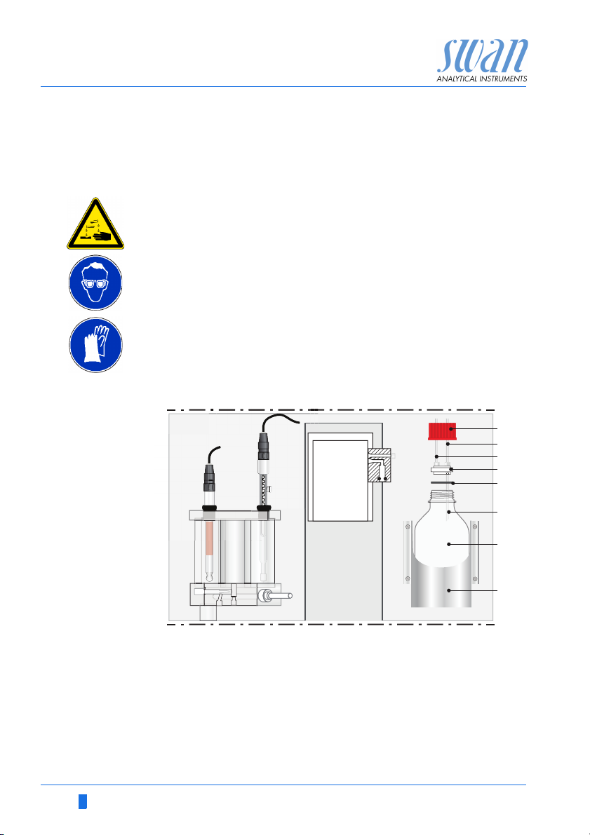
3.5. Install Standard and Regeneration Bottle
Mixing
standard
ABStandard bottle
Bottle holder
Prepare sodium standard using the 1’000 ppm stock solution. The
final concentration must correspond to the concentrations pro-
grammed in the instrument (default = 16 ppm).
1 Before preparing the standard, rinse bottle carefully with high
purity water.
2 Depending on measuring range use amount of stock solution
according table below.
3 Fill up standard bottle to 500 Millliter with high purity water.
4 Turn the bottle holder [B] downwards and screw the standard
bottle firmly on.
5 Turn the bottle holder upwards in vertical position.
CDRegeneration bottle
Pressure compensation
30 A-96.250.551 / 100717

AMI Soditrace
Installation
Meas. Range Amount of standard Result
< 1 ppb 2 ml 4’000 ppb (4 ppm)
< 5 ppb 5 ml 10’000 ppb
< 10 ppb 10 ml 20’000 ppb
NOTICE:
• Do not prepare standards below 1 ppm.
• If using a concentration other then default (16 ppm) change
setting in menu 4.1.3, p. 104
• Especially low concentration standards are preferably
prepared directly in the plastic standard bottle to prevent
contamination.
CAUTION
Upon first installation and after changing the standard concentration, flush the tube well with standard.
See Liquid System Function Test, p. 44
Regeneration
solution
A-96.250.551 / 100717 31
Use only original Swan Regeneration solution.
1 Turn the bottle holder downwards and screw the regeneration
bottle firmly on.
2 Turn the bottle upwards in vertical position
AMI Soditrace
A
B
C
E
F
D
H
G
Installation
3.6. Install Reagent Bottle
WARNING
Diisopropylamine is corrosive.
Read the Safety Data Sheets (SDS) first.
Wear suitable protective clothing, gloves and eye/face protec-
tion.
Avoid inhalation of DIPA vapor. To prevent formation of re-
agent vapors:
– close the reagent bottle firmly
– check the EPDM seal regularly
– In case of contact with eyes, rinse immediately with plenty
of water eyelid wide open for at least 10 min, summon
medical advice. In case of accident or if you feel unwell,
summon medical advice immediately.
A
Screw cover G 45
B
Tube 11 from air lift pump
C
Tube 8 to valve 4
D
Tube holder
The Tubes are already installed into the tube holder [D] and the
EPDM seal [E] seats on the bottom of the tube holder. To install the
DIPA bottle proceed as follows:
32 A-96.250.551 / 100717
E
EPDM seal
F
Short tube
G
DIPA reagent bottle
H
Bottle holder

AMI Soditrace
Installation
1 Put the DIPA bottle [G] into the bottle holder [H]
2 Put the tube holder onto the DIPA bottle
3 Screw the screw cover onto the DIPA bottle and tighten it firmly.
3.7. Install Air Filter
A
B
c
D
ABAir pump
Outlet tube 7 to valve 4
To install the air filter proceed as follows:
1 Push the air filter [D] into the air inlet [C] of the air pump [A] as
far as it will go.
For commissioning of the instrument see chapter 4, Instrument Set-
up, p. 44
A-96.250.551 / 100717 33
CDAir inlet with O-ring seal
Air filter

AMI Soditrace
Installation
3.8. Electrical Connections
Cable
thicknesses
In order to comply with IP66, use the following cable thicknesses
WARNING
Risk of electrical shock.
Do not perform any work on electrical components if the transmitter is switched on. Failure to follow safety instructions could
result in serious injury or death.
Always turn off AC power before manipulating electric parts.
Grounding requirements: Only operate the instrument from
an power outlet which has a ground connection.
Make sure the power specification of the instrument corre-
sponds to the power on site.
ABC
PG 11 cable gland: cable Ø
A
B
PG 7 cable gland: cable Ø
C
PG 9 cable gland: cable Ø
NOTICE: Protect unused cable glands
Wire For Power and Relays: Use max. 1.5 mm
stranded wire with end sleeves.
For Signal Outputs and Input: Use 0.25 mm
stranded wire with end sleeves.
outer
3–6.5 mm
outer
4–8 mm
outer
5–10 mm
2
/ AWG 14
2
/ AWG 23
34 A-96.250.551 / 100717
AMI Soditrace
Installation
WARNING
External Voltage.
External supplied devices connected to relay 1 or 2 or to the
alarm relay can cause electrical shocks
Make sure that the devices connected to the following con-
tacts are disconnected from the power before resuming installation.
– relay 1
– relay 2
– alarm relay
WARNING
To prevent from electrical shock, do not connect the instrument
to the power unless the ground wire (PE) is connected.
Do not connect unless specifically instructed to do so.
WARNING
The mains of the AMI Transmitter must be secured by a main
switch and appropriate fuse or circuit breaker.
A-96.250.551 / 100717 35

AMI Soditrace
Installation
3.8.1 Connection Diagram
CAUTION
Use only the terminals shown in this diagram, and only for the
mentioned purpose. Use of any other terminals will cause short
circuits with possible corresponding consequences to material
and personnel.
36 A-96.250.551 / 100717

AMI Soditrace
A
B
C
D
Installation
3.8.2 Power Supply
WARNING
Risk of electrical shock
Do not perform any work on electrical components if the transmitter is switched on. Failure to follow safety instructions could
result in serious injury or death.
Always turn off AC power before manipulating electric parts.
Installation and maintenance of electrical parts must be per-
formed by professionals.
A
Power supply connector
B
Neutral conductor, Terminal 2
C
Phase conductor, Terminal 1
D
Protective earth PE
NOTICE: The protective earth wire (Ground) has to be
connected to the grounding terminal.
Installation
requirements
A-96.250.551 / 100717 37
The installation must meet the following requirements.
Mains fuse 1.6 AT
Mains cable to comply with standards IEC 60227 or IEC
60245; flammable rating FV1
Mains equipped with an external switch or circuit-breaker
– near the instrument
– easily accessible to the operator
– marked as interrupter for AMI Soditrace

AMI Soditrace
10
12
11
0V
1)
10
12
11
0V
Installation
3.9. Relay Contacts
Programming of the relay contacts see 5.3 Relay Contacts, p. 78
3.9.1 Input
If signal output is set to hold, measurement is interrupted if input is
active.
3.9.2 Alarm Relay
Alarm output for system errors.
Error codes see Troubleshooting, p. 74
NOTICE: Use only potential-free (dry) contacts. The total
resistance (sum of cable resistance and resistance of the relay
contact) must be less than 50 Ω.
• Terminals 30/31
NOTICE: Max. load 1 AT / 250 VAC
NOTICE: With certain alarms and certain settings of the AMI
transmitter the alarm relay does not switch. The error, however,
is shown on the display.
Ter min als Description Relay connection
1)
NC
Normally
Closed
10/11 Active (opened) during normal
operation.
Inactive (closed) on error and
loss of power.
NO
Normally
Open
12/11 Active (closed) during normal
operation.
Inactive (opened) on error and
loss of power.
1) usual use
38 A-96.250.551 / 100717

AMI Soditrace
6
0V
7
6
0V
7
A
B
Installation
3.9.3 Relay Contacts 1 and 2
Relay 1 and 2 can be configured as normally open or as normally
closed. Standard for both relays is normally open. To configure a
Relay as normally closed, set the jumper in the upper position.
NOTICE: Rated load 1 AT / 250 VAC
NOTICE: Some error codes and the instrument status may
influence the status of the relays described below.
Relay
config. Terminals
Normally
Open
Normally
Closed
6/7: Relay 1
8/9: Relay 2
6/7: Relay 1
8/9: Relay 2
Jumper
pos. Description Relay configuration
Inactive (opened) during
normal operation and
loss of power.
Active (closed) when a
programmed function is
executed.
Inactive (closed) during
normal operation and
loss of power.
Active (opened) when a
programmed function is
executed.
ABJumper set as normally open (standard setting)
Jumper set as normally closed
For programming see Menu Installation 5.3.2 and 5.3.3, p. 105
A-96.250.551 / 100717 39

AMI Soditrace
A
BC
DE
Installation
CAUTION
Risk of damage of the relays in the AMI Transmitter due to
heavy inductive load.
Heavy inductive or directly controlled loads (solenoid valves,
dosing pumps) may destroy the relay contacts.
To switch inductive loads > 0.1 A use an AMI relay box avail-
able as an option or suitable external power relays.
Inductive load Small inductive loads (max 0.1A) as for example the coil of a power
Resistive load Resistive loads (max. 1A) and control signals for PLC, impulse
Actuators Actuators, like motor valves, are using both relays: One relay con-
relay can be switched directly. To avoid noise voltage in the
AMI Transmitter it is mandatory to connect a snubber circuit in parallel to the load. A snubber is not necessary if an AMI relaybox is
used.
A
AC or DC power supply
B
AMI Transmitter
C
External power relay
D
Snubber
E
Power relay coil
pumps and so on can be connected without further measures
A
AB
C
tact is used for opening, the other for closing the valve, i.e. with the
2 relay contacts available, only one motor valve can be controlled.
Motors with loads bigger than 0.1A must be controlled via external
power relays or an AMI relay box.
A
BC
AMI Transmitter
B
PLC or controlled pulse pump
C
Logic
A
AC or DC power supply
B
AMI Transmitter
C
Actuator
M
40 A-96.250.551 / 100717

AMI Soditrace
A
B
C
D
Installation
3.10. Signal Outputs
3.10.1 Signal Output 1 and 2 (current outputs)
Signal output 1: Terminals 14 (+) and 13 (-)
Signal output 2: Terminals 15 (+) and 13 (-)
For programming see Program List and Explanations, p. 92, Menu
Installation
3.11. Interface Options
NOTICE: Max. burden 510 Ω.
If signals are sent to two different receivers, use signal isolator
(loop isolator).
A
AMI Transmitter
B
Slot for interfaces
C
Frontend PCB
D
Screw terminals
The slot for interfaces can be used to expand the functionality of
the AMI instrument with either:
Third signal output
a Profibus or Modbus connection
an USB Interface
A-96.250.551 / 100717 41

AMI Soditrace
Installation
3.11.1 Signal Output 3
Terminals 38 (+) and 37 (-).
Requires the additional board for the third signal output 0/4–20 mA.
The third signal output can be operated as a current source or as a
current sink (switchable via switch [A]). For detailed information see
the corresponding installation instruction.
Third signal output 0/4 - 20 mA PCB
A Operating mode selector switch
3.11.2 Profibus, Modbus Interface
Terminal 37 PB, Terminal 38 PA
To connect several instruments by means of a network or to config-
ure a PROFIBUS DP connection, consult the PROFIBUS manual.
Use appropriate network cable.
NOTICE: Max. burden 510 Ω.
A
NOTICE: The switch must be ON, if only one instrument is
installed, or on the last instrument in the bus.
OFF
ON
A
Profibus, Modbus Interface PCB (RS 485)
A On - OFF switch
42 A-96.250.551 / 100717

AMI Soditrace
A
B
Installation
3.11.3 USB Interface
The USB Interface is used to store Logger data and for Firmware
upload. For detailed information see the corresponding installation
instruction.
The optional third signal output 0/4 – 20 mA PCB [B] can be
plugged onto the USB interface and used in parallel.
USB Interface
A USB interface PCB
B Third signal output 0/4 - 20 mA PCB
A-96.250.551 / 100717 43

AMI Soditrace
3.2.1
Service
Test Valve Block
Man. Regeneration
Man. Calibration
Man. Verification
3.2.1.5
Test Valve Block
ModeMeasure
EMF 195.57 mV
Conductivity 450 uS
Timer 410 Sec
3.2.1.5
Test Valve Block
Mode Measure
EMF 195.57 mV
Conductivity 450 uS
Timer 410 Sec
Fill Loop
Mode
Measure
Hi Level
Mix
Instrument Setup
4. Instrument Setup
4.1. Establish Sample Flow
1 Open sample flow tap.
2 Wait until the flow cell is completely filled.
3 Switch on power.
4.2. Liquid System Function Test
The liquid system function test is of vital importance to make sure
that all tubes are filled and connected without leakage and that all
solenoid valves are working properly.
Possible sources of error are listed at the end of each test. Should
an error occur during a test see chapter
correction of errors.
Perform the liquid system function test exactly in the order as described below. Do not start the next test if the current test has failed.
Navigate to Menu <Maintenance>,
<Service>, <Test Valve Block>
Press [Enter]
Troubleshooting, p. 74
for
Mode Measure is already highlighted.
Press [Enter].
Start with the test “Hi Level”,
see chap. 4.2.1, 2 45
Select Mode “Hi Level”.
Press [Enter].
Then continue with the tests
“Fill Loop” see 4.2.2, 2 46
and
“Mix” see 4.2.3, 2 46
44 A-96.250.551 / 100717

AMI Soditrace
V2
V5 V4
V3
V1
Instrument Setup
4.2.1 Hi Level Test
With the test “Hi Level” the function of valve 1 is tested.
High level must be reached within 4 minutes.
Low level
V5 V4
V1
V2
V3
High level
If High Level is not reached within 4 minutes, see Problems During
Valve Block Test, p. 75
A-96.250.551 / 100717 45

AMI Soditrace
V2
V5 V4
V3
V1
Instrument Setup
4.2.2 Fill Loop
With the test “Fill Loop” the function of valve 2 and 3 activated is
tested.
Standard flow is ok if air bubbles are formed in the standard bottle.
If no air bubbles are formed in the standard bottle see Problems
During Valve Block Test, p. 75
4.2.3 Mix
With the test “Mix” the function of valve 2 and 3 is tested. Observe
the mV indication. The mV reading must go through a maximum
within 30 s and reach stable values after 5 min.
V5 V4
V2
V3
V1
If the values ar not stable after 5 min, see Problems During Valve
Block Test, p. 75.
46 A-96.250.551 / 100717

AMI Soditrace
V2
V5 V4
V3
V1
Instrument Setup
4.2.4 Test Valve 5
Navigate to Menu <Man. Regeneration> and start the function regeneration:
The instrument displays the actual state of the regeneration process in the following order: Mix –> Regenerate –> End.
If Regenerate is displayed, valve 5 is opened and regeneration
solution flows through tube 13, valve 5, and tube 10 into the flow
cell. If the flow of regeneration solution is ok if air bubbles are
formed in the regeneration solution bottle and conductivity reading
is > 2000 S.
If the conductivity value is not reached, the Error 22, “No Reg.
Agent” is triggered, see Other Errors, p. 81
A-96.250.551 / 100717 47

AMI Soditrace
Instrument Setup
4.2.5 Test Valve 4
Perform this test only after all other tests have been completed successfully.
With this test the control of valve 4 via conductivity sensor is tested.
WARNING
DIPA is
Flammable
Corrosive
Harmful
Carefully read the Safety Data Sheet before handling DIPA
V5 V4
V1
V2
V3
Return to normal operation, let the instrument run and check the
following parameters.
Menu Diagnostics/Sensors / Cond. Sensor:
Conductivity must fluctuate between 430 and 450 µS/cm
Menu Diagnostics/Sample:
check (Ctl) Actual and Ctl Average
(Ctl) Actual must be < 90 %, if it remains on 100 % the DIPA
bottle is not connected
If the specified values are not reached, see Problems During Valve
Block Test, p. 75
48 A-96.250.551 / 100717

AMI Soditrace
5.1.2.1
Maintenance Plan
Start time18:00:00
Calendar
Delay 300 Sec
Signal Outputs hold
Output/ Control hold
5.1.2.2.1
Calendar
Tuesday
Wednesday
Thursday
Friday
Monday
Instrument Setup
4.3. Programming
4.3.1 Calendar
The implemented calendar is based on the CRON format. It starts
with Sunday and ends with Saturday. Usually a month has three full
weeks and two weeks which are part thereof.
Therefore, if you program a task which has to be carried out weekly,
always program the task in the 2nd, 3rd or 4th week of a month.
Example:
In the table below it can be seen, that if a task is programmed on
Monday in the 1st week, it is not carried out because the week
starts only on Wednesday
Week Sun Mon Tues Wed Thurs Fri Sat
1st 1 2 3 4
2nd567891011
3rd12131415161718
4th19202122232425
Last2627282930
Programming Example how to program a regeneration on Monday in the 3rd
week of a month.
Navigate to Menu <Installation>,
<Sensors>, <Maintenance Plan>
Press <Enter>
Set the desired “Start time”.
Press <Enter>
A-96.250.551 / 100717 49
Navigate to Calendar.
Press <Enter>
Monday is already highlighted.

AMI Soditrace
5.1.2.2.1.1
Monday
1st weekoff
3rd week off
4th week off
Last week off
2nd week off
1st weekoff
3rd week off
4th week off
Last week off
2nd week off
5.1.2.2.1.1
Monday
reg. + ver.
3rd week
off
regenerate
reg. + cal.
5.1.2.2.1.1
Monday
1st weekoff
3rd week regenerate
4th week off
Last week off
2nd week off
Instrument Setup
To change the settings of Monday
Press <Enter>
1st week is already highlighted. Navi-
gate to 3rd week.
Press <Enter>.
Navigate to “regenerate”.
Press <Enter>.
The 3rd week is set to “regenerate”.
Press <Exit>.
Press <Enter> to save.
50 A-96.250.551 / 100717
AMI Soditrace
Exit Enter
BCDA
25.4°C
RUN
448 uS
14:10:45
R1
0.008 ppb
R2
1
Installation
Operation
Diagnostics
Messages
Maintenance
Main Menu
Enter
Exit
Operation
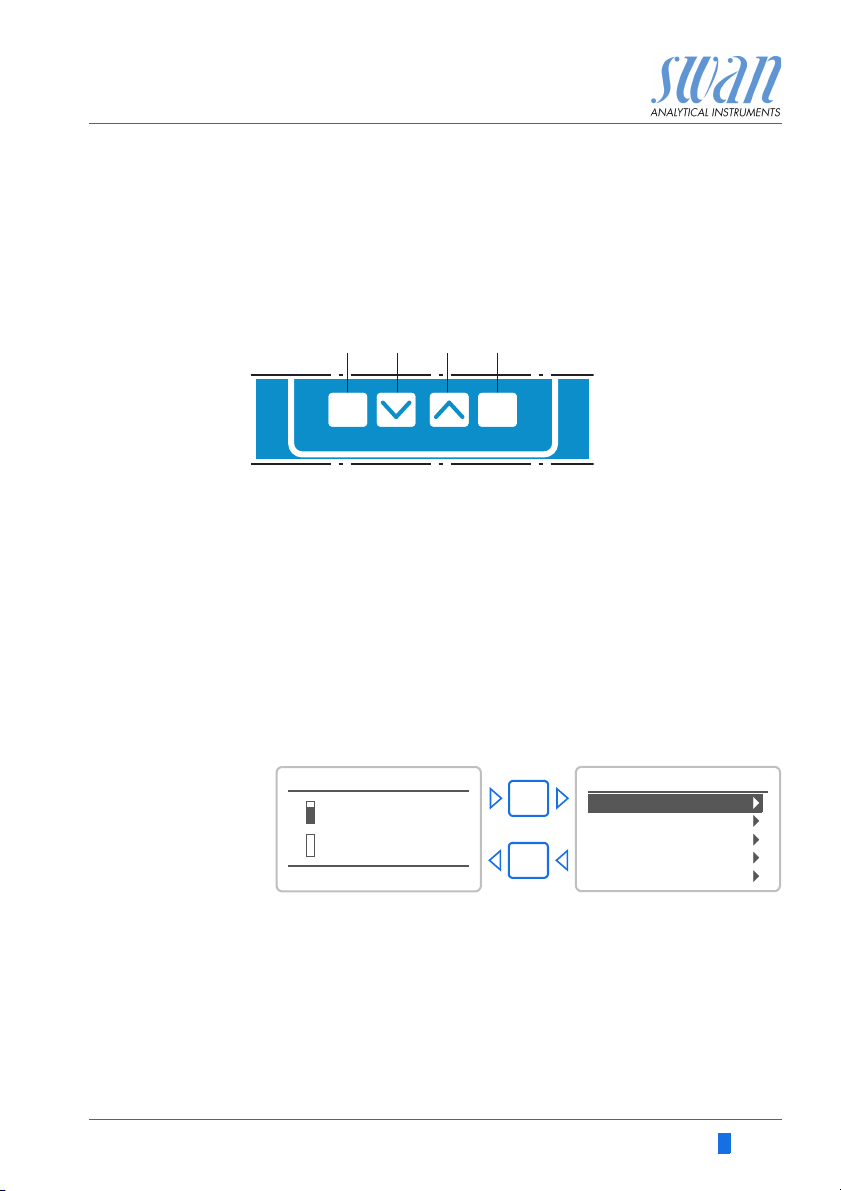
5. Operation
5.1. Keys
A to exit a menu or command (rejecting any changes)
B to move DOWN in a menu list and to decrease digits
C to move UP in a menu list and to increase digits
D to open a selected sub-menu
to move back to the previous menu level
to accept an entry
Program
Access, Exit
A-96.250.551 / 100717 51

AMI Soditrace
RUN
15:20:18
R1
R2
448 µS 24.8°C
ppb
0.008
AB E
F
G
H
I
DC
Operation
5.2. Display
A
B
C
D
E
F
G
H
I
RUN normal operation
HOLD input closed or cal delay: Instrument on hold (shows
status of signal outputs).
OFF input closed: control/limit is interrupted (shows status
ERROR Error
Indicates a verification error
Keys locked, transmitter control via Profibus
Time
Process values
Sample temperature
Conductivity
Relay status
of signal outputs).
Fatal Error
Relay status, symbols
upper/lower limit not yet reached
upper/lower limit reached
control upw./downw. no action
52 A-96.250.551 / 100717
control upw./downw. active, dark bar indicates control intensity
motor valve closed
motor valve: open, dark bar indicates approx. position
timer
timer: timing active (hand rotating)

AMI Soditrace
1
Messages
Operation
Maintenance
Diagnostics
Main Menu
Installation
1.1
Pending Errors
Messages
Maintenance List
Message List
2.1
Interface
I/O State
Sample
Identification
Sensors
Diagnostics
3.1
Process Cal.
Service
Maintenance
Set Time 23.09.06 16:30:00
Simulation
4.1
Logger
Relay Contacts
Sensors
Operation
5.1
Interface
Miscellaneous
Relay Contacts
Sensors
Signal Outputs
Installation
Operation
5.3. Software Structure
Menu Messages 1
Reveals pending errors as well as an event history
(time and state of events that have occurred at an
earlier point of time).
It contains user relevant data.
Menu Diagnostics 2
Provides user relevant instrument and sample data.
A-96.250.551 / 100717 53
Menu Maintenance 3
For instrument calibration, relay and signal output
simulation, and to set the instrument time.
It is used by the service personnel.
Menu Operation 4
User relevant parameters that might need to be
modified during daily routine. Normally password
protected and used by the process-operator.
Subset of menu 5 - Installation, but process-related.
Menu Installation 5
For initial instrument set up by SWAN authorized
person, to set all instrument parameters. Can be
protected by means of password.

AMI Soditrace
5.2.2.1
Signal Output 2
Scaling
Parameter Temperature
Current Loop 4 - 20 mA
Function linear
Scaling
Parameter Temperature
Current Loop 4 - 20 mA
Function linear
5.2.2.1
Signal Output 2
Parameter
Sodium
Temperature
Conductivity
5.2.2.1
Signal Output 2
Parameter Conductivity
Scaling
Current Loop 4 - 20 mA
Function linear
Parameter Conductivity
Scaling
Current Loop 4 - 20 mA
Function linear
5.2.2.1
Signal Output 2
No
Save ?
Yes
5.3.1.1.1
Alarm High 20.0 ppb
Alarm Sodium
Alarm Low 0.000 ppb
Hysteresis 10.0 ppb
Delay 5 Sec
5.3.1.1.1
Alarm Sodium
Alarm Low 0.000 ppb
Hysteresis 10.0 ppb
Delay 5 Sec
Alarm High 9.00 ppb
Operation
5.4. Changing Parameters and values
The following example shows how to change the Signal Output 2:
Changing
parameters
1 Select the parameter you want to
change.
2 Press <Enter>
3 Press < > or< > key to
highlight the required parameter.
4 Press <Enter> to confirm the se-
lection or <Exit> to keep the previous parameter).
The selected parameter is
highlighted (but not saved yet).
5 Press <Exit>.
Yes is highlighted.
6 Press <Enter> to save the new pa-
rameter.
The system reboots, the new
parameter is set.
Changing
values
1 Select the value you want to
change.
2 Press <Enter>.
3 Set required value with < >
or< > key.
4 Press <Enter> to confirm the new
value.
5 Press <Exit>.
Yes is highlighted.
54 A-96.250.551 / 100717
6 Press <Enter> to save the new val-
ue.
AMI Soditrace
Maintenance
6. Maintenance
6.1. Maintenance Schedule
WARNING
Stop operation before maintenance.
Remove DIPA bottle and wait until conductivity is approxi-
mately 0.
Stop sample flow.
Shut off power of the instrument.
Weekly or
every 2 weeks
Monthly Check sealing of reagent bottle, replace if necessary.
Half-yearly Replace sealing of reagent bottle (EPDM)
Yearly Replace valve 4
Reagent
consumption
The following specifications are only valid if the SWAN standard
calendar settings are used.
Check air lift pump for regular bubble formation.
Check level of reagent (DIPA) bottle.
Check level of KCl reservoir.
Check level of regeneration bottle.
Check level of standard bottle.
If necessary refill bottles.
Replace the sodium electrode.
Replace the reference electrode.
If necessary, remove deposited iron in the system by
washing in soft detergent and by using rust remover.
Replace the tubes, if heavily covered with iron.
One 100 ml bottle electrolyte lasts for one month.
500 ml standard solution containing 16 ppm Na lasts for
2months.
500 ml regeneration solution lasts for 4 months.
A-96.250.551 / 100717 55

AMI Soditrace
A
B
D
C
E
Maintenance
6.2. Maintenance of Sodium Electrode
Sodium electrodes are sensitive electrochemical devices with very
high internal impedance. To maintain correct operation, make sure
that.
the sensing glass bulb stays clean
no air bubbles are trapped between glass bulb and glass tube
the electrical connectors stay absolutely clean and dry.
A
Sensor plug
B
Connector cap
C
Union screw
D
Washer
E
O-ring
Remove the
sodium
electrode
Cleaning Remove adhered iron deposits by wiping the electrode gently with
Install See Install the Sodium Electrode, p. 25
1 Unscrew and remove the sensor plug [A].
Take care that the connector stays dry and clean as long as
no electrode is connected.
2 Screw the connector cap onto the sensor.
3 Completely unscrew the union screw [C] from the threaded
hole.
4 Remove the electrode together with the union screw, washer
and O-ring from the measuring cell.
5 Slip the O-ring carefully over the measuring bulb and remove
both nut and washer.
a paper tissue. Rinse the electrode with distilled water.
After installation etch the sodium electrode.
56 A-96.250.551 / 100717

AMI Soditrace
A
B
D
C
E
F
Maintenance
6.3. Maintenance of Reference Electrode
A
Sensor plug
B
Connector cap
C
Union screw
D
Washer
E
O-ring
F
Ring-shaped sleeve
Remove the
reference
electrode
Cleaning 1 Remove any iron deposits with a soft paper tissue.
Install the
reference
electrode
A-96.250.551 / 100717 57
1 Completely unscrew the union screw [C] from the threaded
hole.
2 Remove the KCl bottle from its holder.
Remember that the bottle was punctured - do not spill KCl.
3 Remove the reference electrode from the flow cell.
2 Slip the ring-shaped sleeve [F] upwards with a turning and
pushing movement.
3 Let flow out about 1 ml KCl.
4 Fix the ring-shaped sleeve finger tight with a gentle turning and
pulling movement.
5 Replace or refill KCl reservoir. Use only original SWAN KCl.
See Install the Reference Electrode, p. 26

AMI Soditrace
A
E
F
B
C
D
Maintenance
6.4. Maintenance of Conductivity Sensor
The conductivity sensor is used to maintain a constant conductivity
of 450 µS/cm. To get correct measuring values, it is of vital importance, that the conductivity sensor is installed and aligned correctly.
A
Base plate top view
B
Union screw
C
Conductivity sensor
Remove the
conductivity
sensor
Cleaning Remove any iron deposits with a soft paper tissue. Do not use or-
Install the
conductivity
sensor
1 Completely unscrew the union screw [B] from the threaded
hole.
2 Remove the conductivity sensor from the base plate.
ganic detergents!
1 Insert the conductivity sensor into the base plate.
2 Insert the conductivity sensor so that its sensing tip is aligned
with the outer edge of the sample inlet hole and its measuring
slot is aligned vertically (see dashed red lines).
3 Tighten the union screw.
58 A-96.250.551 / 100717
D
Base plate side view
E
Guiding sleeve
F
O-ring

AMI Soditrace
Maintenance
6.5. Maintenance of Solenoid Valve
NOTICE: Never use the membranes again after a valve has
been opened.
Dismount 1 Drain the measuring cell completely before dismounting a sole-
Disassembling 1 Unscrew solenoid support [C] and bottom nut [O].
noid valve.
2 Tilt the standard and the regeneration bottle down.
3 Remove the tubes from the defective valve.
4 Unscrew knurled nut [A].
5 Pull valve assembly out of coil body [B].
Take care not to loose the springs!
2 Remove the membrane holders.
Normally the membranes stick to the valve body.
3 Remove the membranes with pointed pliers.
Do not use the membranes again!
4 Clean the valve body [H] with soft detergent.
A-96.250.551 / 100717 59

AMI Soditrace
A
B
C
D
E
F
G
H
I
K
L
M
N
O
Maintenance
Drawing
Assembling 1 Put new membranes on the membrane holders.
60 A-96.250.551 / 100717
2 Place membrane 1 with holder in valve body.
3 Place washer 1 on membrane and push down carefully.
4 Place conical spring with smaller end on membrane holder.
5 Screw on the bottom screw finger tightly.
6 Turn valve body upside down and place Teflon distance bar in
Mounting 1 Push valve assembly in coil body.
centre hole of valve body.
7 Place membrane 2 with holder in valve body.
8 Place washer 2 on membrane and push down carefully.
9 Place long spring in solenoid.
10 Screw on the solenoid support finger tightly.
2 Mount all tubes.
3 Only then screw on the knurled nut finger tightly.
A
Knurled nut
B
Coil body
C
Solenoid support
D
Washer 2
E
Long spring
F
Solenoid with membrane holder
G
Membrane 2
H
Valve body
I
Teflon distance bar
K
Membrane 1
L
Membrane holder
M
Conical spring
N
Washer 1
O
Bottom nut

AMI Soditrace
Maintenance
6.6. Maintenance of Flow Cell
CAUTION
Possible damage of acrylic glass parts due to scrubbing
materials.
Never use organic solvents or scrubbing materials to clean
acrylic glass parts.
Use soft detergent and rinse well.
NOTICE: Never use silicone oil or grease to seal standard
bottle holder and o-rings.
Use teflon paste or spray to grease moving parts.
Dismount 1 Shut off the instrument and stop the sample flow.
2 Drain the measuring cell completely by pulling downwards the
two overflow tubes [M] and [N].
3 Tilt the standard and the regeneration bottle down
4 Remove all sensors.
5 Remove all tube connections.
6 Unscrew the M5x70 mm fixing screw of the cover plate [E].
7 Unscrew the two M5x 70 mm fixing screws [S] of the base plate.
8 Remove the measuring cell from the panel.
Disassembling 1 Remove the airlift pump [X].
2 Unscrew and remove the three M5x115 mm screws [D].
3 Remove the cover plate [E].
4 Remove the:
Calibration cell tube [H]
Constant head tube [I]
Reference cell tube [J]
Measuring cell tube [K]
Overflow tube low level [L]
Overflow tube high level [M]
Overflow tube constant head [N]
Conductivity sensor
and their O-rings from the base plate.
Cleaning Clean all parts with a soft detergent and rinse well afterwards.
Grease all O-rings with teflon spray or paste.
A-96.250.551 / 100717 61

AMI Soditrace
A
B
C
D
E
F
F
G
G
H
I
J
K
L
M
N
O
P
Q
R
S
T
U
V
W
X
A
Maintenance
Exploded
drawing
A
Union screw M20
B
Washer
C
O-ring 11 x3.5
D
Screw M5x115
E
Cover plate
F
O-ring 54x3.5
G
O-ring 34x3.5
H
Calibration cell tube
I
Constant head tube
J
Reference cell tube
K
Measuring cell tube
L
Overflow tube low
level
M
Overflow tube high
level
N
Overflow tube
constant head
O
O-ring 21x3
P
O-ring 10x4
Q
Flow regulating valve
R
Base plate
S
Fixing screw M5x70
T
Serto tube adapter
U
O-ring 24x3.5
V
O-ring 11 x3.5
W
Guiding sleeve for
Conductivity sensor
X
Air lift pump
62 A-96.250.551 / 100717

AMI Soditrace
N
U
X
M
105
Maintenance
Assembling 1 Mount the o-rings on all tubes.
2 Insert the measuring cell tube [K] into the inner bore at the left
side of the base plate (see exploded drawing).
3 Insert the overflow tube low level [L] into the inner bore at the
right side of the base plate (see exploded drawing).
4 Insert the Calibration cell tube [H] and the Reference cell tube
[J] into the outer bores of the base plate (see exploded drawing).
5 Insert the constant head tube [I] into the bore of the base plate
(see exploded drawing).
6 Put the cover plate on the tubes and push down firmly until it
rests on the tubes.
7 Screw the flow cell assembly together with the three
M5x115 mm screws. Do not force!
Detail drawing
M
Overflow tube high level
N
Overflow tube constant head
U
O-ring 24x3.5
X
Air lift pump
8 Push the two overflow tubes [M] and [N] through the bores of
the base plate 105 mm into the flow cell, measured from the
lower edge of the base plate (see detail drawing).
9 Mount the airlift pump [X].
Install the flow
cell onto the
panel
A-96.250.551 / 100717 63
1 Screw the cell assembly onto the panel.
2 Mount all tubes according to chapter Tube Replacement, p. 69
3 Install all sensors according to chapter Installation of Elec-
trodes, p. 24.
4 Turn on sample flow and instrument.
NOTICE: Run the instrument in normal operation for at least
24 hours before performing a calibration.

AMI Soditrace
3.1
Service
Simulation
Maintenance
Set Time 05.10.12 16:30:00
Process Cal.
Process Cal.
Offset 25.27 mV
Save <Enter>
Process Value 0.012 ppb
3.1.4
Current Value 0.012 ppb
Process Cal.
Offset 25.27 mV
Save <Enter>
Process Value 0.018 ppb
3.1.4
Current Value 0.012 ppb
3.1.4
Process Cal.
Offset XX mV
Calibration successful
Maintenance
6.7. Process Calibration
The process calibration is based on a comparative measurement of
the on-line instrument with a correct manual measurement with any
instrument. Then compare the measuring value of the manual measurement with the on-line instrument and if necessary, enter the
correct measuring value in the menu <Maintenance/Process Cal.>
of the on-line instrument.
The deviation of the measuring values is shown as offset in mV.
Select <Save> and press <Enter> to save the correct measuring
value.
1 Navigate to <Maintenance>/
<Process Cal.>.
2 Press <[Enter]
The following values are displayed:
Current value
Offset
Process value
Current value and Process value are
equal.
3 Press <[Enter].
4 Enter the Process value mea-
sured with the calibrated comparative electrode.
Use the <> or< >
keys to increase or decrease
the Process value.
5 Press <[Enter] to confirm.
6 Press <[Enter] to save.
The process value is saved and the
new Offset in mV is displayed.
64 A-96.250.551 / 100717

AMI Soditrace
3.2.2.5
Man. Regeneration
<Exit> to cancel
State Mix
EMF -232.52 mV
Conductivity 456 S
Timer 300 Sec
3.2.2.5
Man. Regeneration
Done
State End
EMF -232.52 mV
Conductivity 456 S
Maintenance
6.8. Regeneration
The regeneration is used to etch the sodium sensor periodically.
This guarantees a fast response and reliable measurement values
over al long time and extended life time of the sodium sensor.
If performing
a manual
regeneration
Start a manual
regeneration
Performing a manual regeneration is only recommended after commissioning of the instrument, maintenance work or if the verification
fails. If you perform a manual regeneration consider the following:
Please consider that it takes some hours after a regeneration until
very low sodium values will be displayed correctly again.
Navigate to Menu: <Maintenance/ Service / Man. Regeneration>.
Press <Enter> to start a manual regeneration. It starts immediately.
Start of regeneration procedure:
State: shows the current state
EMF: actual value in mV
Conductivity: actual value in S
Timer: counts from 10 s
Do not perform a manual regeneration if a calibration (manual
or automatic) starts in less than 12 h.
NOTICE: Man. Regeneration does not start if:
• There is no sample flow
• There is no reagent (Diisopropylamine)
• There is too much Reagent (defect valve).
A-96.250.551 / 100717 65
End of regeneration procedure:
State:
EMF: actual value in mV
Conductivity: actual value in S
The settings in <Installation / Sensors / Maintenance Plan> are also
valid during the manual regeneration. This means, the signal
outputs and the Output / Control remain during manual regeneration
and delay time in the programmed state either:
<cont> or <hold> or <off>

AMI Soditrace
3.2.3.5
Man. Calibration
<Exit> to cancel
State Hi Level
Cal. Point - - -
EMF - 173.70 mV
Timer 217 Sec
Maintenance
6.9. Calibration
The 3-point calibration is used to recalculate the slope and determine the offset of the sodium sensor periodically.
The calibration consists of three steps. On each step an exactly defined amount of a known concentration of a standard solution is
added to the closed sample loop. After each addition the concentration is measured and at the end of the calibration slope and offset will be calculated and stored from these measuring values. For
a detailed description of the calibration please refer to
Calibration, p. 14
If performing
a manual
calibration
Start
calibration
Performing a manual calibration is only recommended after commissioning of the instrument or maintenance work. If you perform a
manual calibration consider the following:
Do not run more than one calibration per week.
Wait at least 12 h after a regeneration before performing a
calibration.
Do not run a manual calibration
be performed within the next 12 h, check the calendar.
After start up wait 24 h before performing a calibration.
Please consider that it takes some hours after a calibration until
very low sodium values will be displayed correctly again.
NOTICE: Man. Calibration does not start if:
• There is no sample flow
• There is no reagent (Diisopropylamine)
• There is too much Reagent (defect valve).
Navigate to Menu: <Maintenance/Service/ Man. Calibration>.
Press <Enter> to start the manual calibration.
Start of calibration procedure:
State: Shows all calibration steps
Cal-point: 3 Calibration-points
EMF: actual value in [mV]
Timer: Progress Calibration-time
if an automatic calibration will
66 A-96.250.551 / 100717

AMI Soditrace
3.2.3.5
Man. Calibration
Save <Enter>
Offset 124.00 mV
Slope 59.22 mV
Maintenance
End of calibration procedure:
Press <Enter> to save the
calibration
Press <Exit> to discharge the
calibration
The settings in <Installation / Sensors / Maintenance Plan> are also
valid during the manual regeneration. This means, the signal
outputs and the Output/Control remain during manual calibration
and delay time in the programmed state either:
<cont> or <hold> or <off>
6.10. Verification
The Verification is used to check the response of the sodium electrode. To obtain the best results, start the verification 12 h after a regeneration.
During the verification a precisely defined amount of calibration
solution flows from the standard solution bottle via valve 3 into the
measuring cell.
If the expected measuring value is reached within a predefined
time, the verification was successful.
If the time limit is exceeded start a manual regeneration.
If performing
a manual
verification
Start
verification
Performing a manual verification is only recommended after commissioning of the instrument or maintenance work. If you perform a
manual calibration consider the following:
Navigate to Menu: <Maintenance/ Service/ Man. Calibration>.
Press <Enter> to start the manual verification.
Perform a regeneration before starting a verification.
Wait at least 12 h after a regeneration before performing a
verification.
NOTICE: Man. Verification does not start if:
• There is no sample flow
• There is no reagent (Diisopropylamine)
• There is too much Reagent (defect valve).
A-96.250.551 / 100717 67

AMI Soditrace
3.2.4.5
Man. Verification
<Exit> to cancel
State Hi Level
Current value 0.030 ppb
Timer 217 Sec
3.2.4.5
Man. Verification
Continue with <Enter>
State End
Addition meas. 124.7 ppb
Addition calc. 125.7 ppb
Deviation -0.8 %
Maintenance
Start of verification procedure:
State: Shows all verification steps
Current value:
Timer: Progress Verification time
End of verification procedure:
Addition meas.
Addition calc.
Deviation
The settings in <Installation / Sensors /Maintenance Plan> are also
valid during the manual verification. This means, the signal outputs
and the Output/ Control remain during manual calibration and delay
time in the programmed state either: <cont> or <hold> or <off>
68 A-96.250.551 / 100717

AMI Soditrace
A
B
C
Maintenance
6.11. Tube Replacement
6.11.1 Tube Numbering
Number Length from to
1 155 Measuring Cell Constant Head Valve 2 NC
2 230 Measuring Cell Calibration Cell Valve 2 NO
3 230 Measuring Cell Air lift Pump Valve 3 NO
4 670 Standard Bottle Valve 3 NC
5 90 Measuring Cell Reference Cell Valve 1 NO
6 125 Valve 1 Co Waste
7 670 Air Pump Valve 4 Co
8 700 Reagent Bottle Valve 4 NC
10 350 Measuring Cell Airlift Pump Valve 5 Co
11 670 Measuring Cell Airlift Pump Reagent Bottle
12 186 Valve 4 NO Valve 5 NO
13 800 Valve 5 NC Regeneration bottle
Cal 48.5 Valve 2 Co Valve 3 Co
Reag 60 Inside Reagent Bottle
Solenoid Valve connections
A
Connection NO
B
Connection Co
C
Connection NC
A-96.250.551 / 100717 69

AMI Soditrace
1
6
6
5
5
Co
Co
Co
NO
NO
NO
NC
NC
NC
A
FG
HI
B
J
K
L
M
CD
E
2
3
4
4
3
Cal
2
1
Maintenance
6.11.2 Tube Connections Liquid Handling
70 A-96.250.551 / 100717
A Standard bottle H Air lift pump
E Calibration chamber I Valve 1
F Constant head J Valve 2
G Reference chamber K Valve 3

AMI Soditrace
7
8
8
7
10
11
11
10
12
12
13
13
Co
Co
NO
NO
NC
NC
A
FG
H
I
B
J
K
L
M
CD
E
Maintenance
6.11.3 Tube Connections Reagent and Regeneration Handling
B Regeneration bottle H Air lift pump
C Air pump L Valve 4
D Reagent bottle M Valve 5
A-96.250.551 / 100717 71

AMI Soditrace
A
B
CDEF G
Maintenance
6.12. Replacing Fuses
When a fuse has blown, find out the cause and fix it before replacing it with a new one.
Use tweezers or needle-nosed pliers to remove the defective fuse.
Use original fuses provided by SWAN only.
WARNING
External Voltage.
External supplied devices connected to relay 1 or 2 or to the
alarm relay can cause electrical shocks.
Make sure that the devices connected to the following con-
tacts are disconnected from the power before resuming installation.
–relay 1
–relay 2
– alarm relay
A
B
C
D
E
F
G
1.6 AT/250V Instrument power supply
1.0 AT/250V Relay 1
1.0 AT/250V Relay 2
1.0 AT/250V Alarm relay
1.0 AF/125V Signal output 2
1.0 AF/125V Signal output 1
1.0 AF/125V Signal output 3
72 A-96.250.551 / 100717

AMI Soditrace
Maintenance
6.13. Longer Stop of Operation
1 Stop sample flow.
2 Dismount reagent bottle and close it firmly.
3 Shut off power of the instrument.
WARNING
Diisopropylamine is corrosive.
Read the Safety Data Sheets (SDS) first.
Wear suitable protective clothing, gloves and eye/face protec-
tion.
Avoid inhalation of DIPA vapor. To prevent formation of re-
agent vapors:
– close the reagent bottle firmly
– In case of contact with eyes, rinse immediately with plenty
of water eyelid wide open for at least 10 min, summon
medical advice. In case of accident or if you feel unwell,
summon medical advice immediately.
Wait until 0 S is displayed (Reagent empty error)
NOTICE: If the reagent bottle stays connected to the instrument
reagent vapours damage the membranes of valve 4 and the air
pump.
A-96.250.551 / 100717 73

AMI Soditrace
AB
3
4
5
6
10
11
12
13
7
8
1
2
C
D
OP
V1
V2
V3
V4
V5
Troubleshooting
7. Troubleshooting
7.1. Tubing overview
74 A-96.250.551 / 100717

AMI Soditrace
Troubleshooting
7.2. Problems During Valve Block Test
Hi Level Test If High Level is not reached within 4 minutes check the following:
Possible cause Corrective Action
No sample flow. Check pressure of sample supply
line.
Valve 1 is leaking.
No sample must flow into
the waste via tube 6.
Air pump defective. If the air pump is defect contact our
Fill Loop If no air bubbles are formed in the standard bottle check the follow-
ing:
Possible cause Corrective Action
Air bubbles are trapped in
tube 4.
Valve 2 and/or valve 3
are not working properly.
Repair valve 1, see Maintenance of
Solenoid Valve, p. 59
service to have it replaced.
Wait until <Fill Loop> is active:
Then close the pressure compensation tube of the bottle [A] and
squeeze the bottle until the tube is
filled with standard solution.
If necessary repair valves, see
Maintenance of Solenoid Valve, p.
59
Mix If the values are not stable after 5 min check the following:
Possible cause Corrective Action
Air bubbles are trapped in
tube 2.
Valve 2 and/or valve 3
are not working properly.
A-96.250.551 / 100717 75
If necessary vent tube 2.
If the mV value increases,
Standard leaks into the measuring
cell.
Leakage valve 3
If the mV value decreases,
sample leaks into the measuring
cell.
Leakage valve 2
If necessary repair valves, see
tenance of Solenoid Valve, p. 59
Main-

AMI Soditrace
A
E
F
B
C
D
Troubleshooting
Test valve 5 See Other Errors, p. 81 error 22.
Test valve 4 If the specified end value is not reached, check the following:
Possible cause Corrective Action
DIPA bottle is empty. Refill DIPA bottle.
Screw cover of DIPA bottle not
enough tightened. (a strong
smell of fuel indicates a leakage)
Tube 8 and/ or tube 11 are leaking.
Air pump defective.
Visible if no continuous, regular
stream of air bubbles is formed
beginning from the air inlet [E].
Retighten the screw cover.
Retighten the tube(s).
If the air pump is defect contact our service to have it
replaced.
A
Base plate
B
Conductivity sensor
C
Air lift pump
D
DIPA vapor inlet inactive
(tube 11)
E
Air inlet active (tube 10)
F
Sample inlet
76 A-96.250.551 / 100717

AMI Soditrace
A
E
F
B
C
D
Troubleshooting
Possible cause Corrective Action
Valve 4 defective. Check the following:
Conductivity sensor
wrong positioned.
If valve 4 has switched the air bubble stream has to be stopped for
about 1 second and DIPA vapor
bubbles are formed at the DIPA
vapor inlet [D].
If this is not the case:
Repair valve 4, see Maintenance of
Solenoid Valve, p. 59.
Align the conductivity sensor
according to chapter Maintenance
of Conductivity Sensor, p. 58
A
Base plate
B
Conductivity sensor
C
Air lift pump
D
DIPA vapor inlet active
(tube 11)
E
Air inlet inactive (tube 10)
F
Sample inlet
A-96.250.551 / 100717 77

AMI Soditrace
Troubleshooting
7.3. Calibration Errors
High background, E020
The error High background occurs after the first addition of the cali-
bration. It is triggered if the difference between the pure sample and
the sample after the first addition is too small. Check the following:
Possible cause Corrective Action
Air bubbles trapped in
tube 2.
The concentration of the
standard is too low in
relation to the sample.
Measuring cell contaminated.
Air bubbles trapped in
tube 4.
Valve 2 and/or valve 3
are not working properly.
Check for leakage.
Remove tube 2 from valve 2 and
vent it.
Double the standard concentration
and enter the new concentration in
menu <Operation/Sensors/
Standard>
Let the instrument run for 24 h and
try again.
Wait until <Fill Loop> is active:
Then close the pressure compensation tube of the bottle [A] and
squeeze the bottle until the tube is
filled with standard solution.
Perform test sequence
Hi Level –> Fill loop –> Mix.
See chap 4.2., 2 44. If necessary
repair valve 2 or 3, see Mainte-
nance of Solenoid Valve, p. 59.
78 A-96.250.551 / 100717

AMI Soditrace
Troubleshooting
Sodium offset, E018
The error Sodium offset is related to the second addition of the calibration. It is triggered at the end of the calibration if the response of the
sodium electrode was too slow. If this error occurs do the following:
Possible cause Corrective Action
Wrong concentration of
standard
Sodium electrode too
slow.
Sodium electrode defective.
Sodium slope, E019
The error Sodium slope is related to the third addition of the calibration.It is triggered at the end of the calibration if the sodium or reference electrode does not work properly. If this error occurs check
the following:
Possible cause Corrective Action
KCl flow of the reference
electrode too low.
Sodium electrode too
slow.
Check programmed standard concentration.
Perform a regeneration. See
Regeneration, p. 65
Replace the sodium electrode.
See Maintenance of Sodium Elec-
trode, p. 56
See Maintenance of Reference
Electrode, p. 57.
Perform a regeneration. See
Regeneration, p. 65.
If this does not lead to any improvement, exchange the sodium electrode, see Maintenance of Sodium
Electrode, p. 56.
A-96.250.551 / 100717 79

AMI Soditrace
Troubleshooting
Sodium Stability, E021
The error Sodium stability is triggered if the sodium concentration is
not stable during the calibration procedure. If this error occurs
check the following:
Possible cause Corrective Action
Sodium electrode too
slow.
Valve 1 is leaking.
No sample must flow into
the waste via tube 6.
Valve 2 and/or valve 3
are not working properly.
KCl flow of the reference
electrode is too high.
Check if sodium electrode
is defective.
Perform a regeneration. See
Regeneration, p. 65.
If this does not lead to any improvement, exchange the sodium electrode, see Maintenance of Sodium
Electrode, p. 56.
Perform test High Level, see Hi
Level Test, p. 45. If necessary repair
valve 1, see Maintenance of Sole-
noid Valve, p. 59
Perform test sequence
Hi Level –> Fill loop –> Mix.
See chap 4.2., 2 44. If necessary
repair valve 2, see Maintenance of
Solenoid Valve, p. 59
See Maintenance of Reference
Electrode, p. 57
See Maintenance of Sodium Elec-
trode, p. 56.
If necessary replace the sodium
electrode.
80 A-96.250.551 / 100717

AMI Soditrace
Troubleshooting
7.4. Other Errors
No reagent, E005
Possible cause Corrective Action
DIPA bottle empty. Refill diisopropylamine.
Tubes 8 and/or 11 are not
connected to the DIPA
bottle.
The screw cover of the
DIPA bottle is not tightened well.
The EPDM seal in the
screw cover is brittle.
Valve 4 does not work
properly.
Connect tube 8 and 11 to the DIPA
bottle.
Tighten the screw cover again.
Replace the EPDM seal.
Perform test valve 4, see Test Valve
4, p. 48. If necessary repair valve 4,
see Maintenance of Solenoid Valve,
p. 59.
No sample, E006
Possible cause Corrective Action
No sample flow. Check pressure of sample supply
line.
Air pump defective.
Check if regular bubbles are
formed in the air lift pump.
Remove tube 7 from the inlet of
valve 4 and check if air is pumped
through the tube.
If the air pump is defect contact our
service to have it replaced.
Reagent high, E015
Possible cause Corrective Action
The pH value of the sample is < 7
A-96.250.551 / 100717 81
Check process.

AMI Soditrace
Troubleshooting
No sample flow. Check pressure of sample supply
Valve 4 does not work
properly.
No Reg. Agent, E022
Possible cause Corrective Action
Regeneration bottle
empty.
Air bubbles are trapped in
tube 13.
Valve 5 does not work
properly.
Conductivity sensor
wrong positioned.
Tube 13 is kniked. Replace tube 13.
line.
Perform test valve 4, see Test Valve
4, p. 48. If necessary repair valve 4,
see Maintenance of Solenoid Valve,
p. 59.
Refill regeneration agent.
Wait until <Regenerate> is active:
Then close the pressure
compensation tube of the bottle
[B] and squeeze the bottle until
the tube is filled with regeneration
solution.
Perform test valve 5, see Test Valve
5, p. 47. If necessary repair valve 2
or 3, see Maintenance of Solenoid
Valve, p. 59
Align the conductivity sensor
according to chapter Maintenance
of Conductivity Sensor, p. 58
82 A-96.250.551 / 100717

AMI Soditrace
25.4°C
HOLD
445S
14:10:45
R1
0.014 ppb
R2
1
Installation
Operation
Diagnostics
Messages
Maintenance
Main Menu
1.1
Message List
Pending Errors
Maintenance List
Messages
1.1.5
Pending Errors
Error Code E005
No Reagent
<Enter> to Acknowledge
Troubleshooting
7.5. Error List
Error
Non-fatal Error. Indicates an alarm if a programmed value is exceeded.
Such Errors are marked E0xx (bold and black).
Fatal Error (blinking symbol)
Control of dosing devices is interrupted.
The indicated measured values are possibly incorrect.
Fatal Errors are divided in the following two categories:
Errors which disappear if correct measuring conditions are re-
covered (i.e. Sample Flow low).
Such Errors are marked E0xx (bold and orange)
Errors which indicate a hardware failure of the instrument.
Such Errors are marked E0xx (bold and red)
Error or fatal Error
Error not yet acknowledged.
Check Pending Errors 1.1.5 * and
take corrective action.
Press <ENTER>.
A-96.250.551 / 100717 83
Navigate to menu Messages.
Press <ENTER>.
Navigate to menu Pending Errors.
Press <ENTER>.
Press <ENTER> to acknowledge the
Pending Errors. The Error is reset and
saved in the Message List.
* Menu numbers see
Program Overview, p. 86

AMI Soditrace
Troubleshooting
Error Description Corrective action
E001 Sodium Alarm high
E002 Sodium Alarm low
E003 Cond. Alarm high
E004 Cond. Alarm low
E005 No Reagent
E006 No Sample
E007 Sample Temp. high
E008 Sample Temp. low
E011 Temp. shorted
E012 Temp. disconnected
E013 Case Temp. high
E014 Case Temp. low
E015 Reagent high
– check process
– check programmed value, see 5.3.1.1,
p. 103
– check process
– check programmed value, see 5.3.1.1,
p. 103
– check process, see Other Errors, p. 81
– check programmed value, see 5.3.1.3,
p. 104
– check process, see Other Errors, p. 81
– check programmed value, see 5.3.1.3,
p. 104
– see Other Errors, p. 81
– see Other Errors, p. 81
– check process
– check programmed value, see 5.3.1.2,
p. 104
– check process
– check programmed value, see 5.3.1.2,
p. 104
– Check wiring of temperature sensor
– Check temperature sensor
– Check wiring of temperature sensor
– Check temperature sensor
– check case/environment temperature
– check programmed value, see 5.3.1.4,
p. 104
– check case/environment temperature
– check programmed value, see 5.3.1.5,
p. 104
– see Other Errors, p. 81
84 A-96.250.551 / 100717

AMI Soditrace
Troubleshooting
Error Description Corrective action
E017 Control Timeout
E018 Sodium Offset
E019 Sodium Slope
E020 High Background
E021 Sodium Stability
E022 No Reg. Agent
E024 Input active
E026 IC LM75
E028 Signal output open
E030 EEProm Frontend
E031 Cal. Recout
E032 Wrong Frontend
E033 Power-on
E034 Power-down
E065 Verification Error
– check control device or programming in
Installation, Relay contact, Relay 1/2
see 5.3.2 and 5.3.3, p. 105
–see Calibration Errors, p. 78
–see Calibration Errors, p. 78
–see Calibration Errors, p. 78
–see Calibration Errors, p. 78
–see Other Errors, p. 81
– See If Fault Yes is programmed in
Menu see 5.3.4, p. 109
– call service
– check wiring on signal outputs 1 and 2
– call service
– call service
– call service
– none, normal status
– none, normal status
– information that a verification failed
– check standard, reg. agent electrodes
valves
A-96.250.551 / 100717 85

AMI Soditrace
Program Overview
8. Program Overview
For explanations about each parameter of the menus see Program
List and Explanations, p. 92
Menu 1 Messages informs about pending errors and mainte-
nance tasks and shows the error history. Password protection
possible. No settings can be modified.
Menu 2 Diagnostics is always accessible for everybody. No
password protection. No settings can be modified.
Menu 3 Maintenance is for service: Calibration, simulation of
outputs and set time/date. Please protect with password.
Menu 4 Operation is for the user, allowing to set limits, alarm
values, etc. The presetting is done in the menu Installation
(only for the System engineer). Please protect with password.
Menu 5 Installation: Defining assignment of all inputs and
outputs, measuring parameters, interface, passwords, etc.
Menu for the system engineer. Password strongly recommended.
8.1. Messages (Main Menu 1)
Pending Errors Pending Errors 1.1.5* * Menu numbers
1.1*
Maintenance List Maintenance List 1.2.5*
1.2*
Message List Number 1.3.1*
1.3* Date, Time
86 A-96.250.551 / 100717

AMI Soditrace
Program Overview
8.2. Diagnostics (Main Menu 2)
Identification Designation AMI Soditrace * Menu numbers
2.1* Version V6.10-04/16
Factory Test Instrument 2.1.3.1*
2.1.3* Motherboard
Front End
Operating Time Years / Days / Hours / Minutes / Seconds 2.1.4.1*
2.1.4*
Sensors Sodium Sensor Current Value ppm
2.2* 2.2.1* EMF
Cal. History Number 2.2.1.4.1*
2.2.1.4* Date, Time
Offset
Slope
Ver. History Number 2.2.1.5.1*
2.2.1.5* Date, Time
Addition meas.
Addition calc.
Deviation
Cond. Sensor Current Value 2.2.2.1*
2.2.2* (Raw value 1)
(Raw value 2)
Miscellaneous Case Temp. 2.2.3.1*
2.2.3*
Sample Sample ID 2.3.1*
2.3* Temperature
(NT5K)
Ctl Actual
Ctl Average
I/O State Alarm Relay 2.4.1*
2.4* Relay 1/2 2.4.2*
Input
Signal Output 1/2
Interface Protocol 2.5.1* (only with RS485
2.5* Baud rate interface)
A-96.250.551 / 100717 87

AMI Soditrace
Program Overview
8.3. Maintenance (Main Menu 3)
Process Cal Process Cal. Current Value * Menu numbers
3.1* 3.1.1* Offset
Process Value
Service Test Valve Block EMF
3.2* 3.2.1* Conductivity
Timer
Mode 3.2.1.5*
Man. Regeneration Progress 3.2.2.5*
3.2.2*
Man. Calibration Progress 3.2.3.5*
3.2.3
Man. Verifikation Progress 3.2.4.5*
3.2.4
Simulation Alarm Relay 3.3.1*
3.3* Relay 1 3.3.2*
Relay 2 3.3.3*
Signal Output 1 3.3.4*
Signal Output 2 3.3.5*
Set Time (Date), (Time)
3.4*
88 A-96.250.551 / 100717

AMI Soditrace
Program Overview
8.4. Operation (Main Menu 4)
Sensors Filter Time Const. 4.1.1* * Menu numbers
4.1* Standard 4.1.2*
Verification Additions
4.1.3* Concentration
Relay Contacts Alarm Relay Alarm Sodium Alarm High 4.2.1.1.1*
4.2* 4.2.1* 4.2.1.1* Alarm Low 4.2.1.1.26*
Hysteresis 4.2.1.1.36*
Delay 4.2.1.1.46*
Alarm Conductivity Alarm High 4.2.1.2.1*
4.2.1.2* Alarm Low 4.2.1.2.26*
Hysteresis 4.2.1.2.36*
Delay 4.2.1.2.46*
Relay 1/ 2 Setpoint 4.2.x.100*
4.2.2*/ 4.2.3* Hysteresis 4.2.x.200*
Delay 4.2.x.30*
Input Active 4.2.4.1*
4.2.4* Signal Outputs 4.2.4.2*
Output / Control 4.2.4.3*
Fault 4.2.4.4*
Delay 4.2.4.5*
Logger Log Interval 4.3.1*
4.3* Clear Logger 4.3.2*
A-96.250.551 / 100717 89

AMI Soditrace
Program Overview
8.5. Installation (Main Menu 5)
Sensors Ref. Electrodes 5.1.1* * Menu numbers
5.1* Maintenace Plan Start time 5.1.1.1*
5.1.2* Calendar Monday to Sunday 1st week
5.1.2.2* 5.1.2.2.1 to 5.1.2.2.7* 2nd week
3rd week
4th week
Last week
Delay 5.1.2.3*
Signal Outputs 5.1.2.4*
Output/ Control 5.1.2.5*
Signal Outputs Signal Output 1/2 Parameter 5.2.1.1 - 5.2.2.1*
5.2* 5.2.1* - 5.2.2* Current Loop 5.2.1.2 - 5.2.2.2*
Function 5.2.1.3 - 5.2.2.3*
Scaling Range Low 5.2.x.40.10/10*
5.2.x.40 Range High 5.2.x.40.20/20*
Relay Contacts Alarm Relay Alarm Sodium Alarm High 5.3.1.1.1*
5.3* 5.3.1* 5.3.1.1* Alarm Low 5.3.1.1.26
Hysteresis 5.3.1.1.36
Delay 5.3.1.1.46
Sample Temp. Alarm High 5.3.1.2.1*
5.3.1.2* Alarm Low 5.3.1.2.26*
Alarm Conductivity Alarm High 5.3.1.3.1*
5.3.1.3* Alarm Low 5.3.1.3.26
Hysteresis 5.3.1.3.36
Delay 5.3.1.3.46
Case Temp. high 5.3.1.4*
Case Temp. low 5.3.1.5*
Relay 1/2 Function 5.3.2.1 – 5.3.3.1*
5.3.2* - 5.3.3* Parameter 5.3.2.20–5.3.3.20*
Setpoint 5.3.2.300 – 5.3.3.301*
Hysteresis 5.3.2.400– 5.3.3.401*
Delay 5.3.2.50–5.3.3.50*
Input Active 5.3.4.1*
5.3.4* Signal Outputs 5.3.4.2*
Output/ Control 5.3.4.3*
Fault 5.3.4.4*
Delay 5.3.4.5*
90 A-96.250.551 / 100717

AMI Soditrace
Program Overview
Miscellaneous Language 5.4.1* * Menu numbers
5.4* Set defaults 5.4.2*
Load Firmware 5.4.3*
Password Messages 5.4.4.1*
5.4.4* Maintenance 5.4.4.2*
Operation 5.4.4.3*
Installation 5.4.4.4*
Sample ID 5.4.5*
Interface Protocol 5.5.1* (only with RS485
5.5* Device Address 5.5.21* interface)
Baud Rate 5.5.31*
Parity 5.5.41*
A-96.250.551 / 100717 91

AMI Soditrace
Program List and Explanations
9. Program List and Explanations
1 Messages
1.1 Pending Errors
1.1.5 Provides the list of active errors with their status (active, acknowl-
1.2 Maintenance List
1.2.5 Provides the list of necessary maintenance. Cleared maintenance
1.3 Message List
1.3.1 Shows the error history: Error code, date / time of issue and status
2 Diagnostics
2.1 Identification
2.1.3 Factory Test: Test date of the Instrument and Motherboard
2.1.4 Operating Time: Years / Days / Hours / Minutes / Seconds
edged). If an active error is acknowledged, the alarm relay is active
again. Cleared errors are moved to the Message list.
messages are moved to the Message list.
(active, acknowledged, cleared). 65 errors are memorized. Then
the oldest error is cleared to save the newest error (circular buffer).
In diagnostics mode, the values can only be viewed, not modified.
Desig.: Designation of the instrument.
Ver sion : Firmware of instrument (e.g. V6.10-04/16)
2.2 Sensors
2.2.1 Sodium Sensor:
Current value: Shows the actual measuring value in ppm.
EMF: Electromotive force. Shows the actual voltage potential
between sodium sensor and reference electrode in mV.
2.2.1.4 Cal. History: Shows the diagnostic values of the last calibrations.
Number: Counter of the calibrations
Date, Time: Date and time assigned to a number
Offset: Zero point displacement from the reference position in mV
Slope: Steepness of the straight line in mV/Decade
92 A-96.250.551 / 100717

AMI Soditrace
Program List and Explanations
2.2.1.5 Ver. History: Shows the diagnostic values of the last verifications.
Number: Counter of the verifications
Date, Time:Date and time assigned to a number
addition meas.: measured value of addition of standard
addition calc.: calculated value of addition of standard
Deviation: Deviation of [measured], [calculated] in %
2.2.1 Cond. Sensor:
Current value: Shows the actual measuring value in µS/cm.
(Raw value 1): Uncompensated value in µS/cm.
(Raw value 2): Temperature compensated value in µS/cm.
2.2.3 Miscellaneous:
2.2.3.1 Case Temp: Shows the actual temperature in °C inside the trans-
mitter.
2.3 Sample
2.3.1 Sample ID: Shows the identification assigned to a sample. This
2.4 I/O State
2.4.1/2.4.2
identification is defined by the user to identify the location of the
sample.
Temperature: Shows the actual temperature in °C and NT5K in
Ohm.
Ctl Actual: Actual dosage of Diisopropylamine.
Ctl Average: Average dosage of Diisopropylamine.
Shows actual status of all in- and outputs.
Alarm Relay:
Relay 1 and 2:
Input:
Signal Output 1 and 2:
Signal Output 3 (option):
Active or inactive
Active or inactive
Open or closed
Actual current in mA
Actual current in mA
2.5 Interface
Only available if optional interface is installed.
Shows the programmed communication settings.
A-96.250.551 / 100717 93

AMI Soditrace
Program List and Explanations
3 Maintenance
3.1 Process Cal.
3.1.4 Current Value: shows the actual measuring value in ppm.
3.2 Service
3.2.1 Test Valve Block: The function Test Valve Block provides several
3.2.1.5 EMF: Electromotive force. Shows the voltage potential between
3.2.1.5 Mode: press [Enter] and select the test you want to carry out. You
Offset: shows the offset value in mV of the difference of the
current value and the process value.
Process Value: Enter the measured value of a reference
instrument.
tests to check the proper function of the solenoid valves 1 to 3.
sodium sensor and reference electrode in mV
Conductivity: The conductivity value represents a pH value. The
ideal conductivity value is 450 µS/cm at a pH of 11.
Timer: shoes the elapsed time.
can chose between:
Mode
Measure normal operating mode
Hi Level (see Hi Level Test, p. 45)
Fill Loop (see Fill Loop, p. 46)
Mix (see Mix, p. 46)
3.2.2 Man. Regeneration: If activated, the instrument will immediately
start a regeneration. Please wait at least 12 h before starting a calibration or verification.
EMF: Electromotive force. The potential generated between the
sodium electrode an the reference electrode.
Conductivity: The conductivity value represents a pH value. The
ideal conductivity value is 450 µS/cm at a pH of 11.
Timer: Progress Regeneration-time.
94 A-96.250.551 / 100717

AMI Soditrace
Program List and Explanations
3.2.3 Man. Calibration: If activated, the instrument will immediately start
a calibration without a regeneration. The display shows each calibration step (High level, Background, 1. Calibration Point, 2. Calibration Point, 3. Calibration Point).
State: shows the actual state of the calibration procedure
Cal. Point: shows which calibration measuring point is in progress
EMF: Electromotive force. Shows the actual voltage potential
between sodium sensor and reference electrode in mV.
Timer: Progress Calibration-time
3.2.4 Man. Verification: Perform a manual regeneration 12 h before
3.3 Simulation
starting a verification. If verification is activated, the instrument will
start immediately. The display shows each verification step.
To simulate a value or a relay state, select the
alarm relay
relay 1 and 2
signal output 1 and 2
with the [ ] or [ ] key.
Press the [Enter] key.
Change the value or state of the selected item with the [ ] or
[ ] key.
The value is simulated by the relay/signal output.
3.3.1
3.3.2
3.3.3
3.3.4
3.3.5
3.3.6
Alarm Relay:
Relay 1
Relay 2:
Signal Output 1:
Signal Output 2:
Signal Output 3:
At the absence of any key activities, the instrument will switch back
to normal mode after 20 min. If you quit the menu, all simulated values will be reset.
Active or inactive
Active or inactive
Active or inactive
Actual current in mA
Actual current in mA
Actual current in mA (option)
3.4 Set Time
Adjust date and time.
A-96.250.551 / 100717 95

AMI Soditrace
Program List and Explanations
4 Operation
4.1 Sensors
4.1.1 Filter Time Constant: Used to damp noisy signals. The higher the
4.1.2 Standard: Enter the concentration of your standard.
4.1.3 Verification:
4.1.3.1 Additions: Enter the desired number of additions of standard.
4.2 Relay Contacts
4.3 Logger
4.4.1 Log Interval: Select a convenient log interval. Consult the table be-
filter time constant, the slower the system reacts to changes of the
measured value.
Range: 5–300 Sec
Press [Exit] and save be confirming yes, only then the concentration will be calculated based on the new concentration value.
Range: 500 ppb–800 ppm
Concentration: shows the calculated, expected concentration of
the sample based on the standard concentration and the number
of additions.
See Relay Contacts 1 and 2, p. 39
The instrument is equipped with an internal logger.The logger data
can be copied to a PC with an USB stick if option USB interface is
installed.
The logger can save approx. 1500 data records. The Records consists of: Date, time, alarms, measured value, measured value uncompensated, temperature, flow.
Range: 1 Second to 1 hour
low to estimate the max logging time. When the logging buffer is
full, the oldest data record is erased to make room for the newest
one (circular buffer).
Interval 1 s 5 s 1 min 5 min 10 min 30 min 1 h
Time 25 min 2 h 25 h 5 d 10 d 31 d 62 d
4.4.2 Clear Logger: If confirmed with yes, the complete logger data is de-
leted. A new data series is started.
96 A-96.250.551 / 100717

AMI Soditrace
Program List and Explanations
5 Installation
5.1 Sensors
5.1.1 Ref. Electrode: Only Calomel is possible for this application.
5.1.2 Maintenance Plan: The menu Maintenance Plan includes all settings, necessary to carry out regularly maintenance tasks.
5.1.2.1 Start time. Enter the Time at which you want to start a task.
5.1.2.2 Calendar: The implemented calendar is based on the CRON format. It starts with Sunday and ends with Saturday. Usually a month
has three full weeks and two weeks which are part thereof.
Therefore, if you program a task which has to be carried out weekly,
always program the task in the 2nd, 3rd or 4th week of a month.
Example:
Looking at the table below you can see, that if a task is pro-
grammed on Monday in the 1st week, it is not carried out because
the week only starts on Wednesday!
Week Sun Mon Tues Wed Thurs Fri Sat
1st 1 2 3 4
2nd567891011
3rd12131415161718
4th19202122232425
Last2627282930
5.1.2.2.1 Monday:
5.1.2.2.1.1 1st week: Press <Enter> and select the function which should be
performed at this time.
Available functions:
off (no function will be performed)
regenerate (performs a regeneration of the sodium elec-
trode)
reg. + ver. (A regeneration of the sodium electrode with sub-
sequently verification is performed)
reg. + cal. (A regeneration of the sodium electrode with sub-
sequently calibration is performed)
5.1.2.2.1.2 2nd week: The same functionality as 1st week.
5.1.2.2.1.3 3rd week: The same functionality as 1st week.
5.1.2.2.1.4 4th week: The same functionality as 1st week.
5.1.2.2.1.5 Last week: The same functionality as 1st week.
A-96.250.551 / 100717 97

AMI Soditrace
Program List and Explanations
5.1.2.2.2–
5.1.2.2.7
5.1.2.3 Delay. During the
5.1.2.4 Signal Outputs. the signal outputs can be set to
5.1.2.5 Output/ Control.
Tuesday to Sunday: The same functionality and sub functionality
as Monday.
regeneration
regeneration and verification
regeneration and calibration
and the programmed delay time, the status of the signal outputs,
and relay 1 and 2 will be continuous / hold/ off, as programmed. The
delay is also active during and after
manual regeneration
manual calibration
manual verification
cont
Signal outputs track the actual measuring value during regeneration, calibration or verification and delay time. All programmed alarms are active.
hold
The signal outputs are on hold and the last valid measuring
value is shown during calibration and delay time. Alarms are
not active.
off
The signal outputs are switched off during calibration and delay time. Alarms are not active.
cont
The programmed limits are active during regeneration, calibration or verification and delay time. All programmed alarms
are active.
hold
The limits are on hold during regeneration, calibration or verification and delay time. Alarms are not active.
off
The limits and alarms are not active. The relays are open
during regeneration, calibration or verification and delay time
98 A-96.250.551 / 100717
 Loading...