

Swan Analytical Instruments AMI Deltacon DG Operator's Manual
AMI Deltacon DG
Version 6.00 and higher
s Manual
Operator’
A-96.250.491 / 080416

Customer Support
SWAN and its representatives maintain a fully trained staff of technical specialists
around the world. For any technical question, contact your nearest
SWAN representative, or the manufacturer:
SWAN ANALYTISCHE INSTRUMENTE AG
Studbachstrasse 13
8340 Hinwil
Switzerland
Internet: www.swan.ch
E-mail: support@swan.ch
Document Status
Title:
ID:
Monitor AMI Deltacon DG Operator’s Manual
A-96.250.491
Revision Issue
00 Sept. 2009 Preliminary Edition
01 Nov. 2009 Update to FW release 4.12
02 Feb. 2013 Update to FW release 5.30
03 April 2016 Update to FW release 6.00, mainboard V2.5
© 2016, SWAN ANALYTISCHE INSTRUMENTE AG, Switzerland, all rights reserved
subject to change without notice

AMI Deltacon DG
Table of Contents
1. Safety Instructions . . . . . . . . . . . . . . . . . . . . . . . . . . . . . . . . . . . 3
1.1. Warning Notices . . . . . . . . . . . . . . . . . . . . . . . . . . . . . . . . . . . . . . 4
1.2. General Safety Regulations . . . . . . . . . . . . . . . . . . . . . . . . . . . . . 6
1.3. Restriction for use. . . . . . . . . . . . . . . . . . . . . . . . . . . . . . . . . . . . . 7
2. Product Description . . . . . . . . . . . . . . . . . . . . . . . . . . . . . . . . . . 8
2.1. Description of the System. . . . . . . . . . . . . . . . . . . . . . . . . . . . . . . 8
2.2. Instrument Specification . . . . . . . . . . . . . . . . . . . . . . . . . . . . . . . . 12
2.3. Instrument Overview. . . . . . . . . . . . . . . . . . . . . . . . . . . . . . . . . . . 14
3. Installation. . . . . . . . . . . . . . . . . . . . . . . . . . . . . . . . . . . . . . . . . . 15
3.1. Installation Checklist Monitors . . . . . . . . . . . . . . . . . . . . . . . . . . . 15
3.2. Mounting of Instrument Panel. . . . . . . . . . . . . . . . . . . . . . . . . . . . 16
3.3. Connecting Sample and Waste . . . . . . . . . . . . . . . . . . . . . . . . . . 16
3.3.1 Swagelok Fitting Stainless Steel at Sample Inlet . . . . . . . . . . . 16
3.4. Installation of Cation Exchanger. . . . . . . . . . . . . . . . . . . . . . . . . . 18
3.5. Electrical Connections . . . . . . . . . . . . . . . . . . . . . . . . . . . . . . . . . 19
3.5.1 Connection Diagram . . . . . . . . . . . . . . . . . . . . . . . . . . . . . . . . . 21
3.5.2 Power Supply . . . . . . . . . . . . . . . . . . . . . . . . . . . . . . . . . . . . . . 22
3.6. Input . . . . . . . . . . . . . . . . . . . . . . . . . . . . . . . . . . . . . . . . . . . . . . . 23
3.7. Relay Contacts . . . . . . . . . . . . . . . . . . . . . . . . . . . . . . . . . . . . . . . 23
3.7.1 Alarm Relay. . . . . . . . . . . . . . . . . . . . . . . . . . . . . . . . . . . . . . . . 23
3.7.2 Relay 1 and 2 . . . . . . . . . . . . . . . . . . . . . . . . . . . . . . . . . . . . . . 24
3.8. Signal Outputs . . . . . . . . . . . . . . . . . . . . . . . . . . . . . . . . . . . . . . . 26
3.8.1 Signal Output 1 and 2 (current outputs) . . . . . . . . . . . . . . . . . . 26
3.9. Interface Options . . . . . . . . . . . . . . . . . . . . . . . . . . . . . . . . . . . . . 26
3.9.1 Signal Output 3 . . . . . . . . . . . . . . . . . . . . . . . . . . . . . . . . . . . . . 27
3.9.2 Profibus, Modbus Interface . . . . . . . . . . . . . . . . . . . . . . . . . . . . 28
3.9.3 USB Interface . . . . . . . . . . . . . . . . . . . . . . . . . . . . . . . . . . . . . . 28
4. Instrument Setup . . . . . . . . . . . . . . . . . . . . . . . . . . . . . . . . . . . . 29
4.1. Establish sample flow . . . . . . . . . . . . . . . . . . . . . . . . . . . . . . . . . . 29
4.2. Programming . . . . . . . . . . . . . . . . . . . . . . . . . . . . . . . . . . . . . . . . 29
5. Operation. . . . . . . . . . . . . . . . . . . . . . . . . . . . . . . . . . . . . . . . . . . 31
5.1. Keys . . . . . . . . . . . . . . . . . . . . . . . . . . . . . . . . . . . . . . . . . . . . . . . 31
5.2. Display . . . . . . . . . . . . . . . . . . . . . . . . . . . . . . . . . . . . . . . . . . . . . 31
5.3. Software Structure . . . . . . . . . . . . . . . . . . . . . . . . . . . . . . . . . . . . 33
5.4. Changing Parameters and values . . . . . . . . . . . . . . . . . . . . . . . . 34
A-96.250.491 / 080416 1

AMI Deltacon DG
6. Maintenance . . . . . . . . . . . . . . . . . . . . . . . . . . . . . . . . . . . . . . . . 35
6.1. Maintenance Schedule . . . . . . . . . . . . . . . . . . . . . . . . . . . . . . . . . 35
6.2. Stop of Operation for Maintenance. . . . . . . . . . . . . . . . . . . . . . . . 35
6.3. Maintenance of the Sensor. . . . . . . . . . . . . . . . . . . . . . . . . . . . . . 36
6.3.1 Remove the Sensor from the Flow Cell. . . . . . . . . . . . . . . . . . . 36
6.3.2 Install the Sensor into the Flow Cell . . . . . . . . . . . . . . . . . . . . . 36
6.4. Replace the Ion Exchanger. . . . . . . . . . . . . . . . . . . . . . . . . . . . . . 37
6.5. Changing the inlet filter . . . . . . . . . . . . . . . . . . . . . . . . . . . . . . . . . 39
6.6. Replacing Fuses . . . . . . . . . . . . . . . . . . . . . . . . . . . . . . . . . . . . . . 40
6.6.1 Fuses in the AMI Transmitter . . . . . . . . . . . . . . . . . . . . . . . . . . 40
6.6.2 Fuses in the Degasser Control Unit. . . . . . . . . . . . . . . . . . . . . . 41
6.7. Longer Stop of Operation . . . . . . . . . . . . . . . . . . . . . . . . . . . . . . . 41
7. Troubleshooting . . . . . . . . . . . . . . . . . . . . . . . . . . . . . . . . . . . . . 42
7.1. Error List . . . . . . . . . . . . . . . . . . . . . . . . . . . . . . . . . . . . . . . . . . . . 43
8. Program Overview . . . . . . . . . . . . . . . . . . . . . . . . . . . . . . . . . . . 47
8.1. Messages (Main Menu 1) . . . . . . . . . . . . . . . . . . . . . . . . . . . . . . . 47
8.2. Diagnostics (Main Menu 2) . . . . . . . . . . . . . . . . . . . . . . . . . . . . . . 48
8.3. Maintenance (Main Menu 3) . . . . . . . . . . . . . . . . . . . . . . . . . . . . . 49
8.4. Operation (Main Menu 4) . . . . . . . . . . . . . . . . . . . . . . . . . . . . . . . 50
8.5. Installation (Main Menu 5). . . . . . . . . . . . . . . . . . . . . . . . . . . . . . . 51
9. Program List and Explanations. . . . . . . . . . . . . . . . . . . . . . . . . 53
1 Messages. . . . . . . . . . . . . . . . . . . . . . . . . . . . . . . . . . . . . . . . . . 53
2 Diagnostics . . . . . . . . . . . . . . . . . . . . . . . . . . . . . . . . . . . . . . . . 53
3 Maintenance . . . . . . . . . . . . . . . . . . . . . . . . . . . . . . . . . . . . . . . 56
4 Operation . . . . . . . . . . . . . . . . . . . . . . . . . . . . . . . . . . . . . . . . . . 57
5 Installation . . . . . . . . . . . . . . . . . . . . . . . . . . . . . . . . . . . . . . . . . 59
10. Material Safety Data sheets . . . . . . . . . . . . . . . . . . . . . . . . . . . . 79
10.1. Cation Exchanger Resin SWAN . . . . . . . . . . . . . . . . . . . . . . . . . . 79
11. Default Values . . . . . . . . . . . . . . . . . . . . . . . . . . . . . . . . . . . . . . . 80
12. Index. . . . . . . . . . . . . . . . . . . . . . . . . . . . . . . . . . . . . . . . . . . . . . . 83
13. Notes . . . . . . . . . . . . . . . . . . . . . . . . . . . . . . . . . . . . . . . . . . . . . . 85
2 A-96.250.491 / 080416

AMI Deltacon DG
Safety Instructions
AMI Deltacon DG - Operator’s Manual
This document describes the main steps for instrument setup, operation and maintenance.
1. Safety Instructions
General The instructions included in this section explain the potential risks
Targ et
audience
OM Location The AMI Operator’s Manual shall be kept in proximity of the instru-
Qualification,
Training
associated with instrument operation and provide important safety
practices designed to minimize these risks.
If you carefully follow the information contained in this section, you
can protect yourself from hazards and create a safer work environment.
More safety instructions are given throughout this manual, at the
respective locations where observation is most important.
Strictly follow all safety instructions in this publication.
Operator: Qualified person who uses the equipment
for its intended purpose.
Instrument operation requires thorough knowledge of applications,
instrument functions and software program as well as all applicable
safety rules and regulations.
ment.
To be qualified for instrument installation and operation, you must:
read and understand the instructions in this manual as well as
the Material Safety Data Sheets.
know the relevant safety rules and regulations.
A-96.250.491 / 080416 3
AMI Deltacon DG
Safety Instructions
1.1. Warning Notices
The symbols used for safety-related notices have the following significance:
DANGER
Your life or physical wellbeing are in serious danger if such
warnings are ignored.
Follow the prevention instructions carefully.
WARNING
Severe injuries or damage to the equipment can occur if such
warnings are ignored.
Follow the prevention instructions carefully.
CAUTION
Damage to the equipment, minor injury, malfunctions or incorrect process can be the consequence if such warnings are ignored.
Follow the prevention instructions carefully.
Mandatory
Signs
The importance of the mandatory signs in this manual.
Safety goggles
Safety gloves
4 A-96.250.491 / 080416
AMI Deltacon DG
Safety Instructions
Warning Signs The importance of the warning signs in this manual.
Electrical shock hazard
Corrosive
Harmful to health
Flammable
Warning general
Attention general
A-96.250.491 / 080416 5
AMI Deltacon DG
Safety Instructions
1.2. General Safety Regulations
Legal
Requirements
Spare Parts
and
Disposables
Modifications Modifications and instrument upgrades shall only be carried out by
The user is responsible for proper system operation.
All precautions must be followed to ensure safe operation
of the instrument.
Use only official SWAN spare parts and disposables. If other parts
are used during the normal warranty period, the manufacturer’s
warranty is voided.
an authorized Service Technician. SWAN will not accept responsibility for any claim resulting from unauthorized modification or alteration.
WARNING
Electrical Shock Hazard
If proper operation is no longer possible, the instrument must be
disconnected from all power lines, and measures must be taken
to prevent inadvertent operation.
To prevent from electrical shock, always make sure that the
ground wire is connected.
Service shall be performed by authorized personnel only.
Whenever electronic service is required, disconnect instru-
ment power and power of devices connected to.
– relay 1,
– relay 2,
– alarm relay
WARNING
For safe instrument installation and operation you must read
and understand the instructions in this manual.
WARNING
Only SWAN trained and authorized personnel shall perform the
tasks described in this document.
6 A-96.250.491 / 080416
AMI Deltacon DG
Safety Instructions
1.3. Restriction for use
The AMI Deltacon DG is designed for determination of:
specific (total) conductivity
cation (acid) conductivity after the cation exchanger
degassed conductivity after a sample reboiler in water-steam-
cycles only.
It calculates the pH value and the concentration of the alkaline substance (NH2, Morpholine, etc.) if an alkaline substance is present in
the water.
It is not suitable for pH determination in high purity water before
alkalization reagent addition.
Conditions for pH calculation:
only 1 alkalization agent in the sample
the contamination is mostly NaCl
phosphate concentration is < 0.5 ppm
pH value is > 7.5, and < 11.5
No sand. No oil.
The sample must not contain any particles, which may block the
flow cell. Sufficient sample flow is coercive for the correct function
of the instrument.
WARNING
For safe instrument installation and operation you must read
and understand the instructions in this manual, as well as the
Material Safety Data Sheets (MSDS)
Cation Exchange Resin
Download
MSDS
A-96.250.491 / 080416 7
The current Material Safety Data Sheets (MSDS) for the below listed reagents are available for downloading at www.swan.ch.
Product name: Cation Exchange Resin
Catalogue number: A-82.841.030 and A-82.841.031

AMI Deltacon DG
Product Description
2. Product Description
2.1. Description of the System
Application
Range
Special
Features
Signal
Outputs
Relays Two potential-free contacts programmable as limit switches for
The AMI Deltacon DG is a complete monitoring system for the automatic, continuous measurement of the conductivity before (specific conductivity) and after a cation exchanger (cationic or acid
conductivity) and the conductivity of the re-boiled sample (degassed conductivity).
Based on difference conductivity measurement, the pH of the sample can be calculated.
The application range covers water steam cycles except neutral
treatment.
Many temperature compensation curves for specific conduc-
tivity measurement:
– Strong acids (HCI)
– Strong bases (NaOH)
– Ammonia
– Morpholine
– Ethanolamines
Flow monitoring
Automatic determination of boiling point all 6 h, or if air pres-
sure changes more than 5 hPa.
NOTICE: The boiling point determination can also be started
manually in the menu <Maintenance/Degasser>
Surveillance of resin exhaust.
Calculation of pH according to the VGB 450L, edition 2006
Calculates the concentration of any alkaline substance pres-
ent in the water.
Two signal outputs programmable for measured values (freely scalable, linear, bilinear, log) or as continuous control output (control
parameters programmable).
Current loop: 0/4–20 mA
Maximal burden: 510
Third signal output available as an option.
measuring values, controllers or timer for system cleaning with automatic hold function. Both contacts can be set as normally open or
normally closed with a jumper.
Maximum load: 1 A/ 250 VAC
8 A-96.250.491 / 080416

AMI Deltacon DG
Product Description
Alarm Relay One potential free contact.
Alternatively:
Open during normal operation, closed on error and loss of
power.
Closed during normal operation, open on error and loss of
power.
Summary alarm indication for programmable alarm values and instrument faults.
Input For potential-free contact to freeze the measuring value or to inter-
rupt control in automated installations (hold function or remote-off).
Communica-
tion interface
(optional)
Safety
Features
Measuring
principle
Specific
Conductivity:
Cation Con-
ductivity (Acid
Conductivity):
USB Interface for logger download
RS485 with Fieldbus protocol Modbus or Profibus DP
No data loss after power failure. All data is saved in non-volatile
memory.
Over voltage protection of in- and outputs.
Galvanic separation of measuring inputs and signal outputs.
The analyzer is factory tested and ready for installation and operation.
When a voltage is set between two electrodes in an electrolyte
solution, the result is an electric field which exerts force on the
charged ions: the positively charged cations move towards the negative electrode (cathode) and the negatively charged anions towards the positive electrode (anode). The ions, by way of capture
or release of electrons at the electrodes, are discharged and so a
current I flows through this cycle and the Ohms law V = I×R applies. From the total resistance R of the current loop, only the resistance of the electrolyte solution, respectively its conductivity
of interest.
The cell constant of the sensor is determined by the manufacturer
and is printed on the sensor label. If the cell constant has been programmed in the transmitter, the instrument measures correctly. No
calibration is must be done, the sensor is factory calibrated. Measuring unit is S/cm or S/m.
Conductivity from all ions in the sample, mainly the alkalization
agent. The contribution of impurities is masked by the alkalization
agent.
The alkalization agent is removed in the cation column. All cationic
ions are exchanged with H+, all anionic impurities (ions with negative charge) pass through the column unchanged.
1
/R, is
A-96.250.491 / 080416 9

AMI Deltacon DG
Product Description
Degassed
Conductivity:
Tem per atu re
compensation
Standard
Tem per atu re
Correction or
calibration
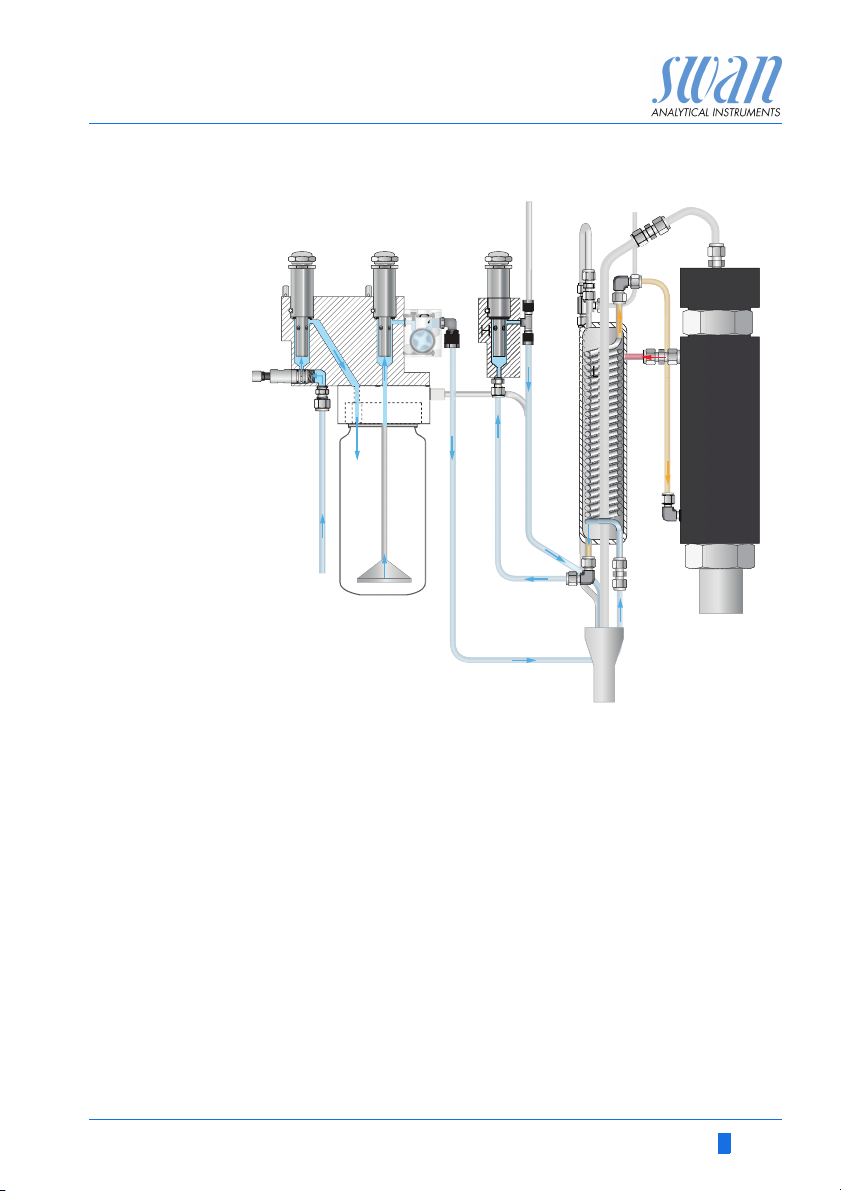
Operation The sample enters at the sample inlet [O] and flows through the
After the heat exchanger the sample is heated up to 0.5 °C below
the boiling point. Hereby volatile components are removed from the
sample, mainly carbon dioxide. Thus, the degassed cation conductivity is a measure of the impurities without a CO2 error.
The mobility of ions in water increase with higher temperature
which enlarges the conductivity. Therefore, the temperature is measured simultaneously by an integrated Pt1000 temperature sensor
and the conductivity is compensated to 25 °C. Several temperature
compensation curves, designed for different water compositions,
can be chosen.
After cation exchanger (cation conductivity), the temperature compensation curve strong acids has to be set.
For more information see: Influence of Temperature on Electrical
Conductivity, PPChem (2012)
The displayed conductivity value is compensated to 25°C standard
temperature.
Not necessary.
Auto zero is done automatically each day at 0.30 at night.
flow regulating valve [I], where the flow rate can be adjusted.
With the first conductivity sensor [A] the specific conductivity (sc) of
the sample is measured. Then the sample is led through the cation
exchanger bottle [P] where all alkalization agent is eliminated. Afterwards the cation conductivity (cc) of the sample is measured
with the second conductivity sensor [B].
The sample leaves the measuring cell through the flow meter [G]
and is led through the heating element of the heat exchanger [L],
where the sample is pre-heated.The pre-heated sample flows then
into the heater [N] where it is heated up to its boiling point. Vapor
leaves the heater via the pressure relief tube [E]. The boiled sample flows via tube [M] back to the heat exchanger where it is cooled
down. Then it flows via tube [R] into flow cell [H] where the degassed conductivity is measured.
The temperature is measured with the temperature sensors integrated in the conductivity sensors.
10 A-96.250.491 / 080416
AMI Deltacon DG
A
FG
H
I
L
J
K
M
OP
Q
RS
T
N
B
CDE
Product Description
Fluidics
overview
A-96.250.491 / 080416 11
A
Conductivity sensor (sc)
B
Conductivity sensor (cc)
C
Conductivity sensor (dc)
D
Heat exchanger pressure
relief tube
E
Heater pressure relief tube
F
Flow cell 1, (sc, cc)
G
Flow meter
H
Flow cell 2, (dc)
I
Flow regulating valve
J
Manual deaeration valve
K
Deaeration tube cation
exchanger bottle
L
Heat exchanger
M
Connection tube
N
Heater
O
Sample inlet
P
Cation exchanger bottle
Q
Connection tube
R
Inlet to Flow cell (dc)
S
Sample outlet
T
Waste

AMI Deltacon DG
Product Description
2.2. Instrument Specification
Power Supply Voltage: 100–127 VAC and
200–240 VAC (± 10%)
50/60 Hz (± 5%)
Max. current:
Voltage at 90 VAC: 12 A
Voltage at 140 VAC: 19 A
Voltage higher than 180 VAC: 9.5 A
Max. power consumption:
Voltage at 90 VAC: 1.1 kW
Voltage at 140 VAC: 2.6 kW
Voltage at 265 VAC: 2.6 kW
Average power consumption: 1.2 kW
Sample
requirements
Flow rate: 5–15 l/h
Temperature: up to 50 °C
Inlet pressure: up to 2 bar
Outlet pressure: pressure free
On-site
requirements
Measuring
range
Accuracy ± 1 % of measuring value (up to 5 mS/cm)
Electronics
housing
The analyzer site must permit connections to:
Sample inlet: Swagelok 1/4” adapter for
stainless steel tube
Sample outlet: 13/16” steel tube
Measuring range Resolution
0.055 to 0.999 S/cm 0.001 S/cm
1.00 to 9.99 S/cm 0.01 S/cm
10.0 to 99.9 S/cm 0.1 S/cm
100 to 1000 S/cm 1 S/cm
Automatic range switching.
± 3 % of measuring value (up to 30 mS/cm)
Aluminium with a protection degree of IP 66 / NEMA 4X
Ambient temperature: -10 to +50 °C
Humidity: 10–90% rel., non condensing
Display: backlit LCD, 75 x 45 mm
12 A-96.250.491 / 080416
AMI Deltacon DG
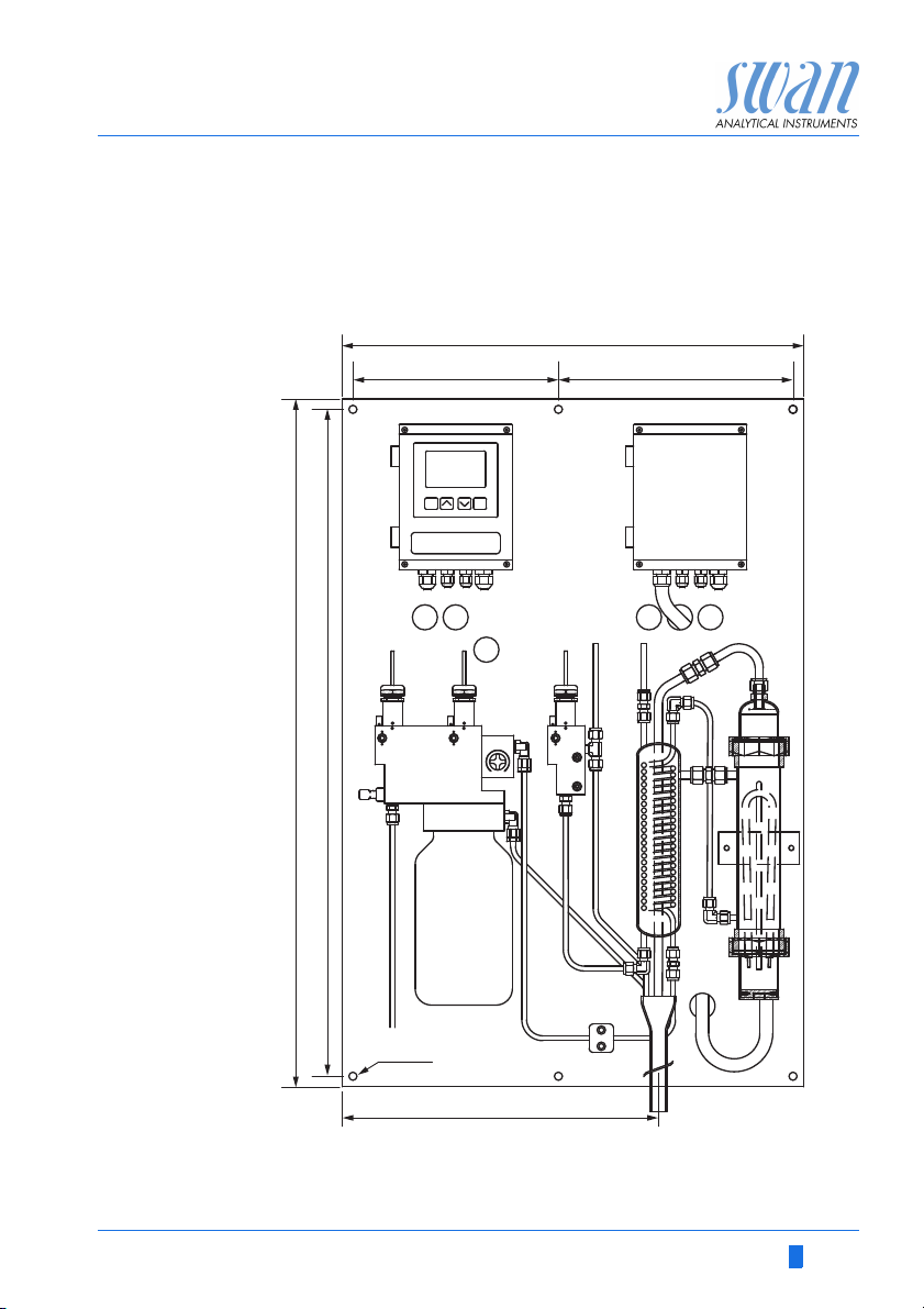
824
570
850
390
6x Ø10
290254
Product Description
Dimensions Panel:
Dimensions:
Screws:
Weight:
Stainless steel
570 x 850 x 200 mm
8 mm
26 kg
A-96.250.491 / 080416 13
AMI Deltacon DG
A
B
C
D
E
F
G
H
I
J
K
L
M
N
O
P
Product Description
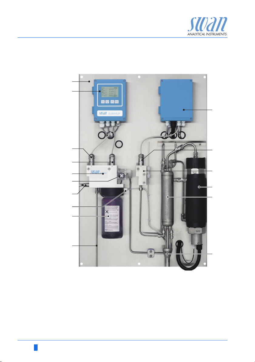
2.3. Instrument Overview
A
Panel
B
Transmitter
C
Specific conductivity sensor
D
Cation conductivity sensor
E
Flow cell 1, sc, cc
F
Flow meter
G
Flow regulating valve
H
Manual deaeration valve
14 A-96.250.491 / 080416
I
Cation exchanger
J
Sample inlet
K
Degasser controller
L
Degassed conductivity sensor
M
Flow cell 2, dc
N
Heater
O
Heat exchanger
P
Waste
AMI Deltacon DG
Installation
3. Installation
3.1. Installation Checklist Monitors
Check Instrument’s specification must conform to your AC power ratings.
Do not turn on power until instructed to do so.
On site requirements
Installation Mounting of Instrument Panel, p. 16.
Cation
exchanger
Electrical Wiring
Power-up Open sample flow and wait until flow cell is completely filled.
Instrument
set-up
Degasser
Run-in period
100–127 VAC, 200–240 VAC (± 10%), 50/60 Hz (± 5%) isolated
power outlet with ground connection and 2.6 kW
Sample line with sufficient sample flow and pressure (see Instru-
ment Specification, p. 12.
Connecting Sample and Waste, p. 16.
Monitor: Sensors are already mounted.
Fill up cation exchanger bottle with high purity water.
Remove the empty bottle and install the cation exchanger bottle.
NOTICE: Do not switch on the Instrument until all electrical
connections are made.
Connect all external devices like limit switches, current loops and
pumps (see Connection Diagram, p. 21.)
Connect power cord, see Power Supply, p. 22.
Manually deaerate the cation exchanger bottle.
Switch on power.
Adjust sample flow.
Program all parameters for the sensors (cell constant, temperature
correction, cable length, temperature compensation for specific
conductivity).
If required activate calculations. Program all parameters for external devices (interface, recorders, etc.).
Program all parameters for instrument operation (limits, alarms).
Program display screens.
The instrument is delivered with the degassing unit switched off.
To switch the unit on, follow the instruction in chapter 4, Program-
ming, p. 29.
Let the instrument run continuously for 1 h. This is valid for rinsed
cation exchanger resin (nuclear grade) delivered by Swan.
If you do not use rinsed cation exchanger resin, the run-in period
may be much longer.
A-96.250.491 / 080416 15

AMI Deltacon DG
Installation
3.2. Mounting of Instrument Panel
The first part of this chapter describes the preparing and placing of
the system for use.
The instrument must only be installed by trained personnel.
Mount the instrument in vertical position.
For ease of operation mount it so that the display is at eye
level.
For the installation a kit containing the following installation
material is available:
– 6 Screws 8 x60 mm
– 6 Dowels
– 6 Washers 8.4/24 mm
Mounting re-
quirements
3.3. Connecting Sample and Waste
The instrument is only intended for indoor installation.
For dimensions see Dimensions, p. 13.
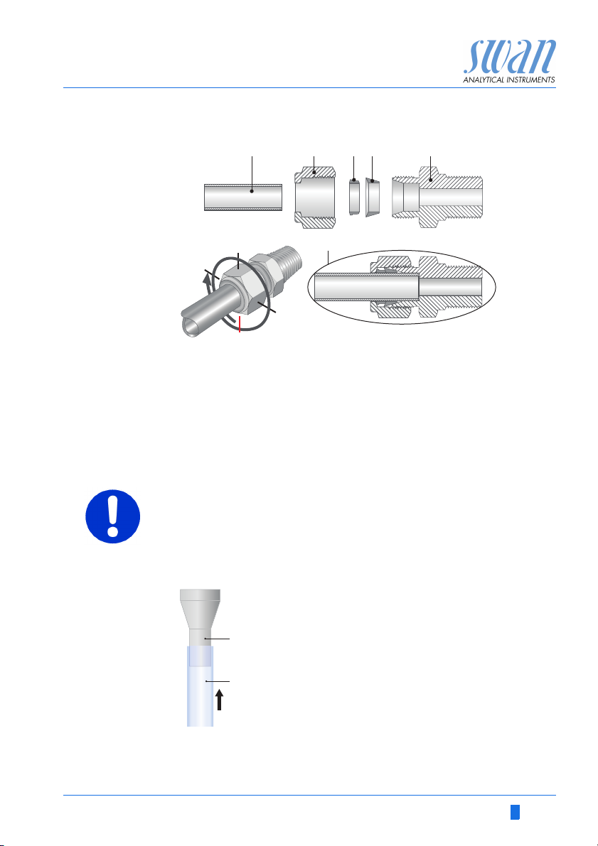
3.3.1 Swagelok Fitting Stainless Steel at Sample Inlet
Preparation Cut the tube to length and deburr it. The tube must be straight and
free from blemishes for approximately 1,5 x tube diameter from the
end.
Lubrication with lubricating oil, MoS2, Teflon etc. is recommended
for the assembly and reassembly of bigger sized unions (thread,
compression cone).
Installation 1 Insert the compression ferrule [C] and the compression
cone [D] into the union nut [B].
2 Screw on the union nut onto the body, do not tighten it.
3 Push the stainless steel pipe through the union nut as far as it
reaches the stop of the body.
4 Mark the union nut at 6 o’clock position.
5 While holding the fitting body steady, tighten the nut union 1¼
rotation using an open ended spanner.
16 A-96.250.491 / 080416
AMI Deltacon DG
12
3
9
6
ABCDE
F
A
B
Installation
A
Stainless steel tube
B
Union nut
C
Compression ferrule
Waste Connect the waste tube to the waste funnel.
D
Compression cone
E
Body
F
Tightened connection
CAUTION
Hot water and steam
Hot water and steam leaves the sample outlet, PVC tubes may
be damaged.
Do not use PVC tubes but silicon tubes for the waste line
ABSteel tube13/16”
Silicon tube
A-96.250.491 / 080416 17
AMI Deltacon DG
Installation
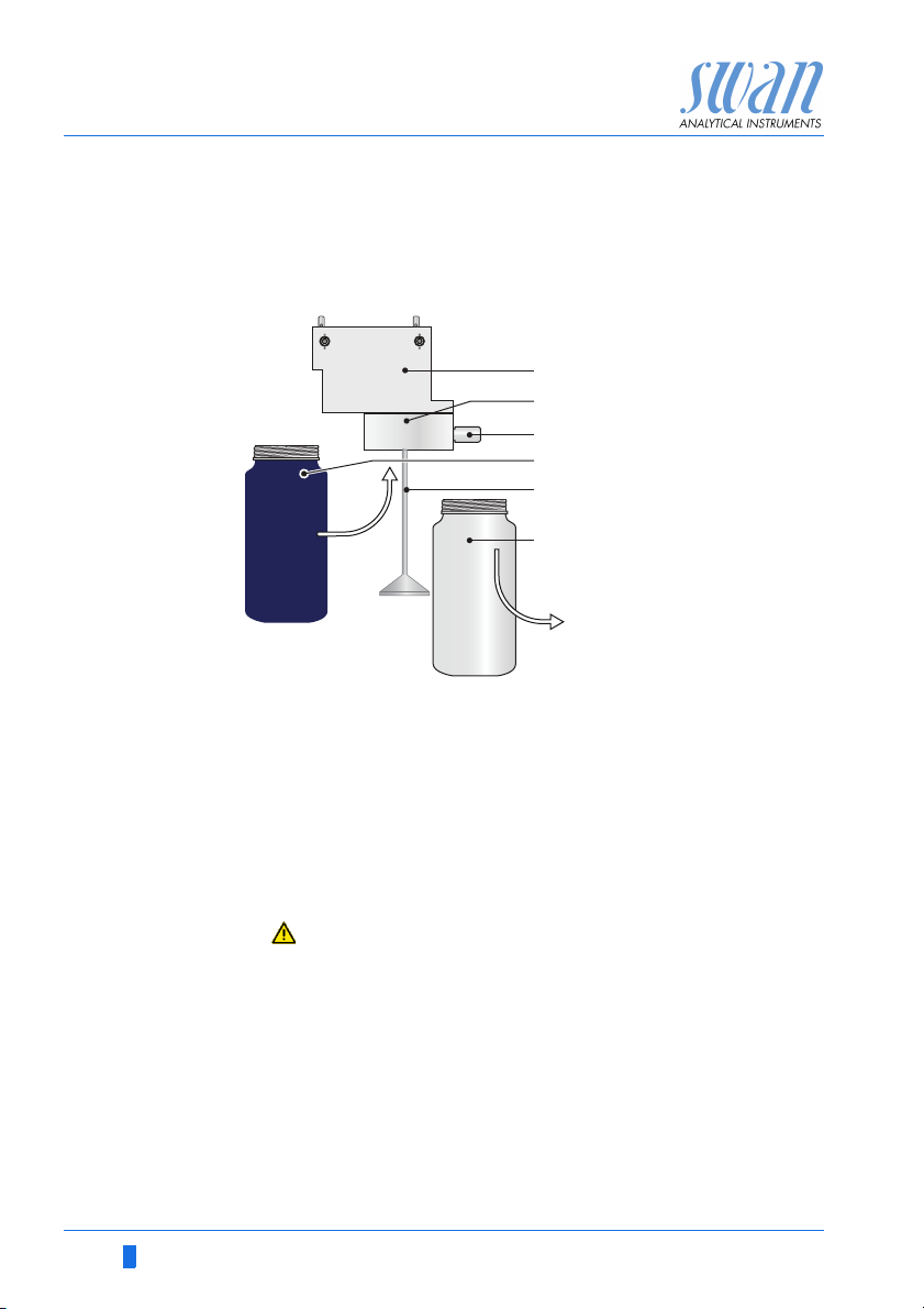
3.4. Installation of Cation Exchanger
Cation ex-
changer bottle
Install cation
exchanger
bottle
The bottle containing the cation exchanger is delivered separately.
For transport, an empty bottle is installed into the bottle holder.
A
Flow cell
B
Bottle holder
C
A
B
C
D
E
F
Install the cation exchanger bottle as follows:
1 Unscrew and remove the empty bottle [F] from the bottle holder
[B].
2 Fill high purity water into the cation exchanger bottle [D], until
the water level in the bottle reaches the beginning of the thread.
3 Carefully, without spilling water, push the cation exchanger bot-
tle over the inlet filter holder [E] into the bottle holder [B].
4 Screw the cation exchanger bottle into the bottle holder.
Do not tighten the bottle too firmly, this could damage the
gasket.
5 Open the manual deaeration valve [C].
6 Open the flow regulating valve.
7 After a few minutes close the manual deaeration valve.
Manual deaeration valve
D
Cation exchanger bottle
E
Inlet filter holder
F
Empty bottle
18 A-96.250.491 / 080416
AMI Deltacon DG
ABC
Installation
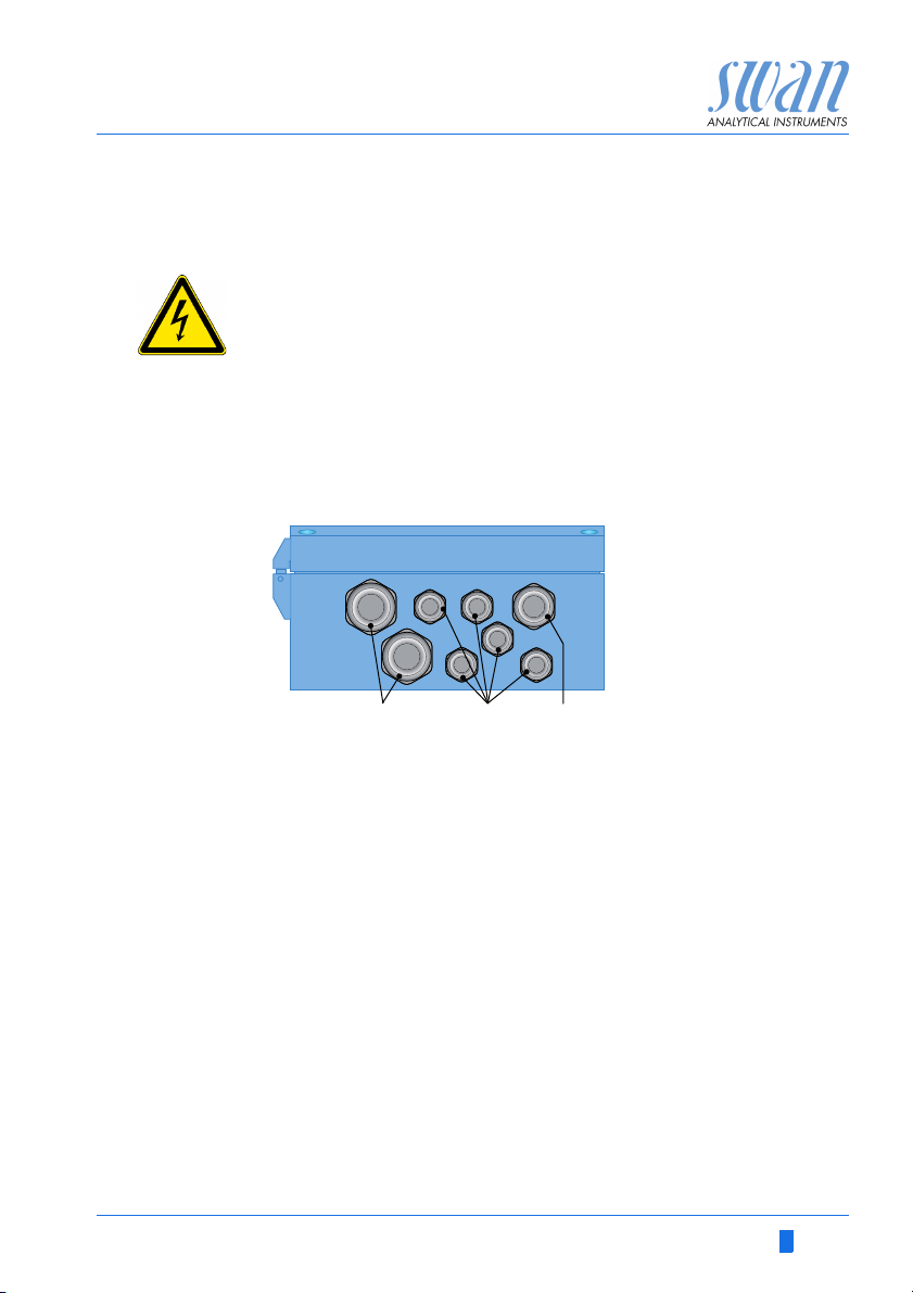
3.5. Electrical Connections
WARNING
Electrical hazard.
Always turn off AC power before manipulating electric parts.
Grounding requirements: Only operate the instrument from
an power outlet which has a ground connection.
Make sure the power specification of the instrument corre-
sponds to the power on site.
Cable
thicknesses
Wire For Power and Relays: Use max. 1.5 mm
In order to comply with IP66, use the following cable thicknesses
A
PG 11 cable gland: cable Ø
B
PG 7 cable gland: cable Ø
PG 9 cable gland: cable Ø
C
outer
3–6.5 mm
outer
4–8 mm
outer
5–10 mm
NOTICE: Protect unused cable glands
2
/ AWG 14
stranded wire with end sleeves.
For Signal Outputs and Input: Use 0.25 mm
2
/ AWG 23
stranded wire with end sleeves.
A-96.250.491 / 080416 19
AMI Deltacon DG
Installation
WARNING
External Voltage.
External supplied devices connected to relay 1 or 2 or to the
alarm relay can cause electrical shocks
Make sure that the devices connected to the following con-
tacts are disconnected from the power before resuming installation.
–relay 1
–relay 2
– alarm relay
WARNING
To prevent from electrical shock, do not connect the instrument
to the power unless the ground wire (PE) is connected.
Do not connect unless specifically instructed to do so.
WARNING
The mains of the AMI Transmitter must be secured by a main
switch and appropriate fuse or circuit breaker.
20 A-96.250.491 / 080416
AMI Deltacon DG
Installation
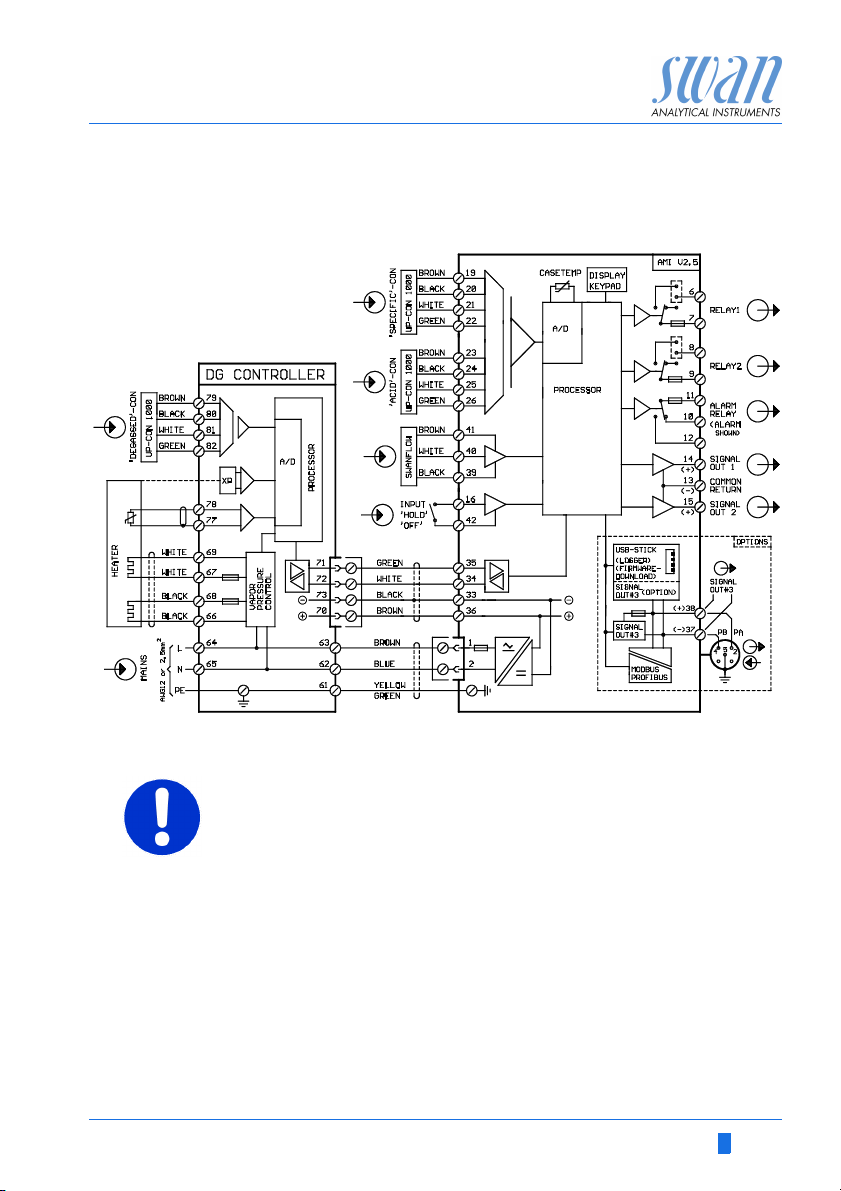
3.5.1 Connection Diagram
CAUTION
Use only the terminals shown in this diagram, and only for the
mentioned purpose. Use of any other terminals will cause short
circuits with possible corresponding consequences to material
and personnel.
A-96.250.491 / 080416 21
AMI Deltacon DG
A
B
E
C
D
Installation
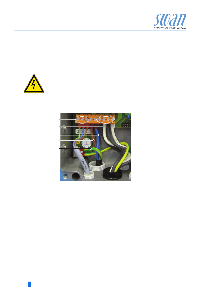
3.5.2 Power Supply
The mains supply is connected to the degasser controller. From
there the AMI transmitter and the heater are supplied.
WARNING
Electrical shock hazard
Installation and maintenance of electrical parts must be performed by professionals
Always turn off AC power before manipulating electric parts.
Already connected
external devices.
D
Transmitter supply
E
Heater supply
Mains
connection
Installation
requirements
A
Neutral conductor
B
Phase conductor
C
Protective earth
NOTICE: The protective earth wire (Ground) has to be
connected to the grounding terminal.
The installation must meet the following requirements.
Mains cable to comply with standards IEC 60227 or IEC
60245; flammable rating FV1
Mains equipped with an external switch or circuit-breaker
– near the instrument
– easily accessible to the operator
– marked as interrupter for AMI Deltacon DG
22 A-96.250.491 / 080416
AMI Deltacon DG
10
12
11
0V
Installation
3.6. Input
NOTICE: Use only potential-free (dry) contacts.
The total resistance (sum of cable resistance and resistance of
the relay contact) must be less than 50 Ω.
Terminals 16/42
For programming see Program Overview, p. 47.
3.7. Relay Contacts
3.7.1 Alarm Relay
NOTICE: Max. load1 A / 250 VAC
Alarm output for system errors.
Error codes see Troubleshooting, p. 42.
NOTICE: With certain alarms and certain settings of the AMI
transmitter the alarm relay does not switch. The error, however,
is shown on the display.
Terminals Description Relay connection
0V
1)
11
10
12
1)
NC
Normally
Closed
NO
Normally
Open
10/11 Active (opened) during normal
operation.
Inactive (closed) on error and
loss of power.
12/11 Active (closed) during normal
operation.
Inactive (opened) on error and
loss of power.
1) usual use
A-96.250.491 / 080416 23
AMI Deltacon DG
6
0V
7
6
0V
7
A
B
Installation
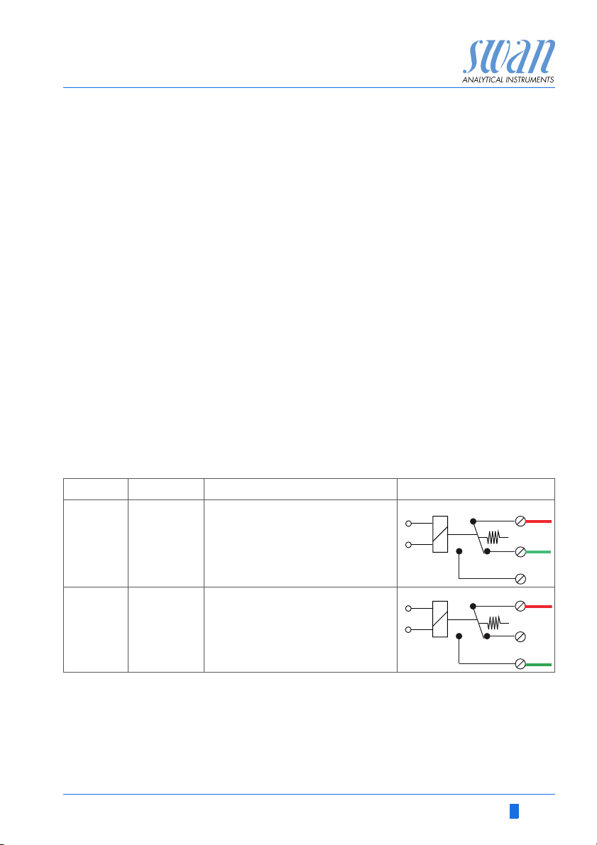
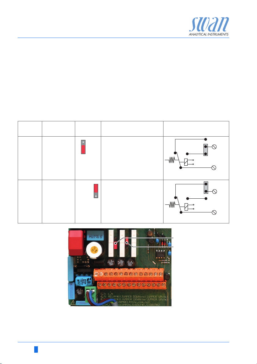
3.7.2 Relay 1 and 2
NOTICE: Max. load 1 A / 250 VAC
Relay 1 and 2 can be configured as normally open or as normally
closed. Standard for both relays is normally open. To configure a
Relay as normally closed, set the jumper in the upper position.
NOTICE: Some error codes and the instrument status may
influence the status of the relays described below.
Relay
config. Terminals
Normally
Open
Normally
Closed
6/7: Relay 1
8/9: Relay 2
6/7: Relay 1
8/9: Relay 2
Jumper
pos. Description Relay configuration
Inactive (opened) during
normal operation and
loss of power.
Active (closed) when a
programmed function is
executed.
Inactive (closed) during
normal operation and
loss of power.
Active (opened) when a
programmed function is
executed.
ABJumper set as normally open (standard setting)
Jumper set as normally closed
For programming see Menu Installation 5.3.2 & 3, p. 71
24 A-96.250.491 / 080416
AMI Deltacon DG
A
BC
DE
AB
C
Installation
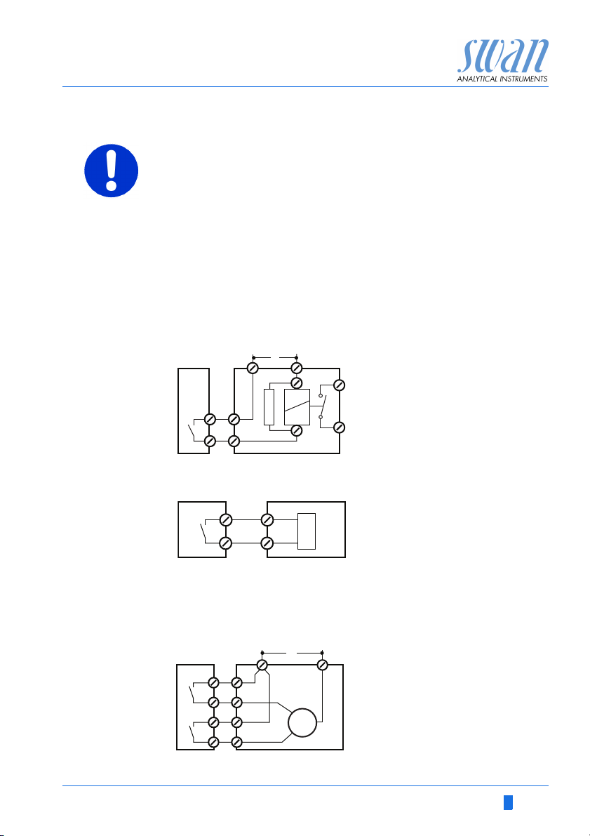
CAUTION
Risk of damage of the relays in the AMI Transmitter due to
heavy inductive load.
Heavy inductive or directly controlled loads (solenoid valves,
dosing pumps) may destroy the relay contacts.
To switch inductive loads > 0.1 A use an AMI relay box avail-
able as an option or suitable external power relays.
Inductive load Small inductive loads (max 0.1A) as for example the coil of a power
Resistive load Resistive loads (max. 1A) and control signals for PLC, impulse
Actuators Actuators, like motor valves, are using both relays: One relay con-
relay can be switched directly. To avoid noise voltage in the
AMI Transmitter it is mandatory to connect a snubber circuit in parallel to the load. A snubber is not necessary if an AMI relaybox is
used.
A
AC or DC power supply
B
AMI Transmitter
C
External power relay
D
Snubber
E
Power relay coil
pumps and so on can be connected without further measures
A
AMI Transmitter
B
PLC or controlled pulse pump
C
Logic
tact is used for opening, the other for closing the valve, i.e. with the
2 relay contacts available, only one motor valve can be controlled.
Motors with loads bigger than 0.1A must be controlled via external
power relays or an AMI relay box.
A
A
BC
AC or DC power supply
B
AMI Transmitter
C
Actuator
A-96.250.491 / 080416 25
M
 Loading...