


AMI Codes-II TC
Version 6.20 and higher
s Manual
Operator’
A-96.250.631 / 280219

Customer Support
SWAN and its representatives maintain a fully trained staff of technical specialists
around the world. For any technical question, contact your nearest
SWAN representative, or the manufacturer:
SWAN ANALYTISCHE INSTRUMENTE AG
Studbachstrasse 13
8340 Hinwil
Switzerland
Internet: www.swan.ch
E-mail: support@swan.ch
Document Status
Title:
ID:
AMI Codes-II TC Operator’s Manual
A-96.250.631
Revision Issue
01 November 2010 First edition
02 December 2013 Update to Rev. 5.40, mainboard V2.4
03 May 2017 Update to Rev. 6.00, mainboard V2.5
© 2017, SWAN ANALYTISCHE INSTRUMENTE AG, Switzerland, all rights reserved
subject to change without notice

AMI Codes-II TC
Table of Contents
1. Safety Instructions . . . . . . . . . . . . . . . . . . . . . . . . . . . . . . . . . . . 4
1.1. Warning Notices . . . . . . . . . . . . . . . . . . . . . . . . . . . . . . . . . . . . . . 5
1.2. General Safety Regulations . . . . . . . . . . . . . . . . . . . . . . . . . . . . . 7
1.3. Restrictions for use. . . . . . . . . . . . . . . . . . . . . . . . . . . . . . . . . . . . 8
2. Product Description . . . . . . . . . . . . . . . . . . . . . . . . . . . . . . . . . . 9
2.1. Instrument Specification . . . . . . . . . . . . . . . . . . . . . . . . . . . . . . . . 15
2.2. Instrument Overview. . . . . . . . . . . . . . . . . . . . . . . . . . . . . . . . . . . 17
3. Installation. . . . . . . . . . . . . . . . . . . . . . . . . . . . . . . . . . . . . . . . . . 18
3.1. Installation Check List. . . . . . . . . . . . . . . . . . . . . . . . . . . . . . . . . . 18
3.2. Mounting of Instrument Panel. . . . . . . . . . . . . . . . . . . . . . . . . . . . 19
3.3. Connecting Sample and Waste . . . . . . . . . . . . . . . . . . . . . . . . . . 19
3.3.1 FEP Tube at Sample Inlet . . . . . . . . . . . . . . . . . . . . . . . . . . . . . 19
3.3.2 FEP Tube at Sample Outlet . . . . . . . . . . . . . . . . . . . . . . . . . . . 20
3.4. Installation of Flow Cell. . . . . . . . . . . . . . . . . . . . . . . . . . . . . . . . . 20
3.5. Install the Option pH . . . . . . . . . . . . . . . . . . . . . . . . . . . . . . . . . . . 22
3.5.1 pH as Option ex works . . . . . . . . . . . . . . . . . . . . . . . . . . . . . . . 22
3.5.2 pH Option as Retrofit Kit . . . . . . . . . . . . . . . . . . . . . . . . . . . . . . 23
3.6. Electrical Connections . . . . . . . . . . . . . . . . . . . . . . . . . . . . . . . . . 26
3.6.1 Connection Diagram . . . . . . . . . . . . . . . . . . . . . . . . . . . . . . . . . 28
3.6.2 Power Supply . . . . . . . . . . . . . . . . . . . . . . . . . . . . . . . . . . . . . . 29
3.7. Input . . . . . . . . . . . . . . . . . . . . . . . . . . . . . . . . . . . . . . . . . . . . . . . 30
3.8. Relay Contacts . . . . . . . . . . . . . . . . . . . . . . . . . . . . . . . . . . . . . . . 30
3.8.1 Alarm Relay. . . . . . . . . . . . . . . . . . . . . . . . . . . . . . . . . . . . . . . . 30
3.8.2 Relay 1 and 2 . . . . . . . . . . . . . . . . . . . . . . . . . . . . . . . . . . . . . . 31
3.9. Signal Outputs . . . . . . . . . . . . . . . . . . . . . . . . . . . . . . . . . . . . . . . 33
3.9.1 Signal Output 1 and 2 (current outputs) . . . . . . . . . . . . . . . . . . 33
3.10 Interface Options . . . . . . . . . . . . . . . . . . . . . . . . . . . . . . . . . . . . . 33
3.10.1 Signal Output 3 . . . . . . . . . . . . . . . . . . . . . . . . . . . . . . . . . . . . . 34
3.10.2 Profibus, Modbus Interface . . . . . . . . . . . . . . . . . . . . . . . . . . . . 34
3.10.3 HART Interface . . . . . . . . . . . . . . . . . . . . . . . . . . . . . . . . . . . . . 35
3.10.4 USB Interface . . . . . . . . . . . . . . . . . . . . . . . . . . . . . . . . . . . . . . 35
A-96.250.631 / 280219 1

AMI Codes-II TC
4. Instrument Setup . . . . . . . . . . . . . . . . . . . . . . . . . . . . . . . . . . . . 36
4.1. Prepare Reagents. . . . . . . . . . . . . . . . . . . . . . . . . . . . . . . . . . . . . 36
4.2. Peristaltic Pump . . . . . . . . . . . . . . . . . . . . . . . . . . . . . . . . . . . . . . 36
4.3. Establish Sample Flow . . . . . . . . . . . . . . . . . . . . . . . . . . . . . . . . . 37
4.4. Fill or Flush Reagent System . . . . . . . . . . . . . . . . . . . . . . . . . . . . 38
4.5. Programming . . . . . . . . . . . . . . . . . . . . . . . . . . . . . . . . . . . . . . . . 38
4.6. Calibration. . . . . . . . . . . . . . . . . . . . . . . . . . . . . . . . . . . . . . . . . . . 39
5. Operation. . . . . . . . . . . . . . . . . . . . . . . . . . . . . . . . . . . . . . . . . . . 40
5.1. Keys . . . . . . . . . . . . . . . . . . . . . . . . . . . . . . . . . . . . . . . . . . . . . . . 40
5.2. Display . . . . . . . . . . . . . . . . . . . . . . . . . . . . . . . . . . . . . . . . . . . . . 41
5.3. Software Structure . . . . . . . . . . . . . . . . . . . . . . . . . . . . . . . . . . . . 42
5.4. Changing Parameters and values. . . . . . . . . . . . . . . . . . . . . . . . . 43
6. Maintenance . . . . . . . . . . . . . . . . . . . . . . . . . . . . . . . . . . . . . . . . 44
6.1. Maintenance Schedule . . . . . . . . . . . . . . . . . . . . . . . . . . . . . . . . . 44
6.2. Stop of Operation for Maintenance. . . . . . . . . . . . . . . . . . . . . . . . 45
6.3. Refill or replace Reagents. . . . . . . . . . . . . . . . . . . . . . . . . . . . . . . 46
6.3.1 Reagents for Measuring Total Chlorine. . . . . . . . . . . . . . . . . . . 49
6.4. Verification . . . . . . . . . . . . . . . . . . . . . . . . . . . . . . . . . . . . . . . . . . 50
6.5. Calibration. . . . . . . . . . . . . . . . . . . . . . . . . . . . . . . . . . . . . . . . . . . 51
6.6. Cleaning the protective Filter . . . . . . . . . . . . . . . . . . . . . . . . . . . . 54
6.7. Cleaning the Photometer . . . . . . . . . . . . . . . . . . . . . . . . . . . . . . . 55
6.8. Cleaning the Flow Cell . . . . . . . . . . . . . . . . . . . . . . . . . . . . . . . . . 56
6.8.1 Disassemble the Flow Cell . . . . . . . . . . . . . . . . . . . . . . . . . . . . 56
6.8.2 Assemble the Flow Cell. . . . . . . . . . . . . . . . . . . . . . . . . . . . . . . 57
6.9. Maintenance of pH sensor . . . . . . . . . . . . . . . . . . . . . . . . . . . . . . 58
6.10. Tube Replacement . . . . . . . . . . . . . . . . . . . . . . . . . . . . . . . . . . . . 59
6.10.1 Replace the Pump Tubes . . . . . . . . . . . . . . . . . . . . . . . . . . . . . 59
6.10.2 Replace the Reagent Tubes . . . . . . . . . . . . . . . . . . . . . . . . . . . 61
6.11. Cleaning the solenoid valve . . . . . . . . . . . . . . . . . . . . . . . . . . . . . 62
6.12. Longer Stop of Operation . . . . . . . . . . . . . . . . . . . . . . . . . . . . . . . 64
7. Troubleshooting . . . . . . . . . . . . . . . . . . . . . . . . . . . . . . . . . . . . . 65
7.1. General Instructions . . . . . . . . . . . . . . . . . . . . . . . . . . . . . . . . . . . 65
7.2. Calibration Errors . . . . . . . . . . . . . . . . . . . . . . . . . . . . . . . . . . . . . 66
7.2.1 Process calibration tc2 . . . . . . . . . . . . . . . . . . . . . . . . . . . . . . . 66
7.2.2 Process pH . . . . . . . . . . . . . . . . . . . . . . . . . . . . . . . . . . . . . . . . 66
7.2.3 Standard pH . . . . . . . . . . . . . . . . . . . . . . . . . . . . . . . . . . . . . . . 66
7.3. Error List . . . . . . . . . . . . . . . . . . . . . . . . . . . . . . . . . . . . . . . . . . . . 67
7.4. Opening the peristaltic pump housing. . . . . . . . . . . . . . . . . . . . . . 72
7.5. Replacing Fuses . . . . . . . . . . . . . . . . . . . . . . . . . . . . . . . . . . . . . . 73
2 A-96.250.631 / 280219

AMI Codes-II TC
8. Program Overview . . . . . . . . . . . . . . . . . . . . . . . . . . . . . . . . . . . 74
8.1. Messages (Main Menu 1) . . . . . . . . . . . . . . . . . . . . . . . . . . . . . . . 74
8.2. Diagnostics (Main Menu 2). . . . . . . . . . . . . . . . . . . . . . . . . . . . . . 75
8.3. Maintenance (Main Menu 3). . . . . . . . . . . . . . . . . . . . . . . . . . . . . 76
8.4. Operation (Main Menu 4) . . . . . . . . . . . . . . . . . . . . . . . . . . . . . . . 77
8.5. Installation (Main Menu 5) . . . . . . . . . . . . . . . . . . . . . . . . . . . . . . 78
9. Program List and Explanations. . . . . . . . . . . . . . . . . . . . . . . . . 80
1 Messages . . . . . . . . . . . . . . . . . . . . . . . . . . . . . . . . . . . . . . . . . 80
2 Diagnostics . . . . . . . . . . . . . . . . . . . . . . . . . . . . . . . . . . . . . . . . 80
3 Maintenance . . . . . . . . . . . . . . . . . . . . . . . . . . . . . . . . . . . . . . . 82
4 Operation. . . . . . . . . . . . . . . . . . . . . . . . . . . . . . . . . . . . . . . . . . 84
5 Installation . . . . . . . . . . . . . . . . . . . . . . . . . . . . . . . . . . . . . . . . . 85
10. Material Safety Data sheets . . . . . . . . . . . . . . . . . . . . . . . . . . . . 100
10.1. Reagents . . . . . . . . . . . . . . . . . . . . . . . . . . . . . . . . . . . . . . . . . . . 100
11. Default Values. . . . . . . . . . . . . . . . . . . . . . . . . . . . . . . . . . . . . . . 101
12. Index . . . . . . . . . . . . . . . . . . . . . . . . . . . . . . . . . . . . . . . . . . . . . . 105
13. Notes . . . . . . . . . . . . . . . . . . . . . . . . . . . . . . . . . . . . . . . . . . . . . . 107
A-96.250.631 / 280219 3

AMI Codes-II TC
Safety Instructions
AMI Codes-II TC - Operator’s Manual
This document describes the main steps for instrument setup, operation and maintenance.
1. Safety Instructions
General The instructions included in this section explain the potential risks
Targ et
audience
OM Location The AMI Operator’s Manual shall be kept in proximity of the instru-
Qualification,
Training
associated with instrument operation and provide important safety
practices designed to minimize these risks.
If you carefully follow the information contained in this section, you
can protect yourself from hazards and create a safer work environment.
More safety instructions are given throughout this manual, at the
respective locations where observation is most important.
Strictly follow all safety instructions in this publication.
Operator: Qualified person who uses the equipment
for its intended purpose.
Instrument operation requires thorough knowledge of applications,
instrument functions and software program as well as all applicable
safety rules and regulations.
ment.
To be qualified for instrument installation and operation, you must:
read and understand the instructions in this manual as well as
the Material Safety Data Sheets.
know the relevant safety rules and regulations.
4 A-96.250.631 / 280219

AMI Codes-II TC
Safety Instructions
1.1. Warning Notices
The symbols used for safety-related notices have the following significance:
DANGER
Your life or physical wellbeing are in serious danger if such
warnings are ignored.
Follow the prevention instructions carefully.
WARNING
Severe injuries or damage to the equipment can occur if such
warnings are ignored.
Follow the prevention instructions carefully.
CAUTION
Damage to the equipment, minor injury, malfunctions or incorrect process can be the consequence if such warnings are ignored.
Follow the prevention instructions carefully.
Mandatory
Signs
A-96.250.631 / 280219 5
The importance of the mandatory signs in this manual.
Safety goggles
Safety gloves
AMI Codes-II TC
Safety Instructions
Warning Signs The importance of the warning signs in this manual.
Electrical shock hazard
Corrosive
Harmful to health
Flammable
Warning general
Attention general
6 A-96.250.631 / 280219
AMI Codes-II TC
Safety Instructions
1.2. General Safety Regulations
Legal
Requirements
Spare Parts
and
Disposables
Modifications Modifications and instrument upgrades shall only be carried out by
The user is responsible for proper system operation.
All precautions must be followed to ensure safe operation
of the instrument.
Use only official SWAN spare parts and disposables. If other parts
are used during the normal warranty period, the manufacturer’s
warranty is voided.
an authorized Service Technician. SWAN will not accept responsibility for any claim resulting from unauthorized modification or alteration.
WARNING
Risk of Electrical Shock
If proper operation is no longer possible, the instrument must be
disconnected from all power lines, and measures must be taken
to prevent inadvertent operation.
To prevent from electrical shock, always make sure that the
ground wire is connected.
Service shall be performed by authorized personnel only.
Whenever electronic service is required, disconnect instru-
ment power and power of devices connected to.
– relay 1,
– relay 2,
– alarm relay
WARNING
For safe instrument installation and operation you must read
and understand the instructions in this manual.
WARNING
Only SWAN trained and authorized personnel shall perform the
tasks described in this document.
A-96.250.631 / 280219 7

AMI Codes-II TC
Safety Instructions
1.3. Restrictions for use
The sample must not contain any particles, which may block the
flow cell. Sufficient sample flow is coercive for the correct function
of the instrument.
If the sample contains only little disinfectant concentrations, or
there is the danger of biological growth, we recommend to use the
optional Cleaning module from Swan.
WARNING
Health hazard
Some reagents are etching and can cause severe burns or eye
damage.
For safe handling of the reagents you must read and under-
stand the instructions in this manual, as well as the Material
Safety Data Sheets (MSDS)
Download
MSDS
The current Material Safety Data Sheets (MSDS) for the below listed Reagents are available for downloading at www.swan.ch.
OXYCON ON-LINE DPD
OXYCON ON-LINE Buffer
OXYCON ON-LINE KI
Buffer solution pH 4
Buffer solution pH 7
Buffer solution pH 9
8 A-96.250.631 / 280219

AMI Codes-II TC
Product Description
2. Product Description
Application
Range
Disinfectant
Measurement
Operating
Modes
Signal
Outputs
The AMI Codes-II TC is a complete monitoring system for the automatic, continuous measurement and dosing control of chlorine
based on the DPD colorimetric method APHA 4500 Cl-G and on
EN ISO 7393-2.
It can be used for measuring disinfectants in:
Pools and sanitary water
Cooling water
Waste water effluent
It is also applicable for water containing additives like corrosion inhibitors, cyanuric acid and antiscaleants.
Determines total chlorine (tc1 and tc2) and calculates dichloramine.
Necessary reagents:
Oxycon on-line DPD
Oxycon on-line Buffer
Oxycon on-line KI
Disinfectant Measuring range Accuracy
Total chlorine
(Standard Mode)
Total chlorine
(Extended Mode)
Two operating modes are available depending on the desired measuring range. Default mode “Standard” for concentrations up to 5
ppm. Select “Extended” for measurements up to 10 ppm which will
lead to higher reagent consumption.
Two signal outputs programmable for measured values (freely
scaleable, linear or bilinear) or as continuous control output (control
parameters programmable).
Current loop: 0/4– 20 mA
Maximal burden: 510
Third signal output available as an option. The third signal output
can be operated as a current source or as a current sink (selectable
via switch).
0.00– 1.00 ppm
1.00– 3.00 ppm
3.00– 5.00 ppm
0.0–10 ppm ± 10%
± 0.01 ppm
± 0.06 ppm
± 0.20 ppm
A-96.250.631 / 280219 9

AMI Codes-II TC
Product Description
Relay Two potential-free contacts programmable as limit switches for
measuring values, controllers or timer for system cleaning with automatic hold function. Both contacts can be used as normally open
or normally closed.
Maximum load: 1 A/250 VAC
Alarm Relay One potential free contact.
Alternatively:
Open during normal operation, closed on error and loss of
power.
Closed during normal operation, open on error and loss of
power.
Summary alarm indication for programmable alarm values and instrument faults.
Input For potential-free contact to freeze the measuring value or to inter-
Special
Feature
Safety
Features
Communica-
tion Interface
(optional)
Relay Box The AMI Relay Box is designed for the direct power supply and ac-
Cleaning
Module
rupt control in automated installations (hold function or remote-off).
Possibility to interrupt the measurement by activating the input. See
Program List and Explanation, 5.3.4, p. 97.
No data loss after power failure. All data is saved in non-volatile
memory. Over voltage protection of in- and outputs.Galvanic separation of measuring inputs and signal outputs.
USB Interface for logger download.
Third signal output (can be used in parallel to the USB interface)
RS485 with Fieldbus protocol Modbus or Profibus DP
HART interface
pH Optional pH measurement is possible (pH correction or calibration).
tivation of dosing devices which are controlled with an AMI transmitter, e. g. to connect two solenoid valves or one motor valve for
disinfectant additions.
An optional Cleaning module is available.
10 A-96.250.631 / 280219

AMI Codes-II TC
cdc
3-5 sec
DPD
Buffer
KI
@ 2 min
0 sec
tc2
tc1
2 min
Time
[ppm]
Val ue
Product Description
Glossary Abbreviations used for the chlorine forms measured:
Abbr. Te rm Comment
tc1 Total chlorine 1 Immediate reaction of DPD + KI
(mainly monochloramine)
tc2 T
otal chlorine 2 Reaction with DPD + KI after 2
min. reaction
cdc C
pH/T pH
B/s B
alculated dichloramine cdc = tc2 - tc1
and Temperature (Optional)
ubbles per second Sample flow
A-96.250.631 / 280219 11

AMI Codes-II TC
Product Description
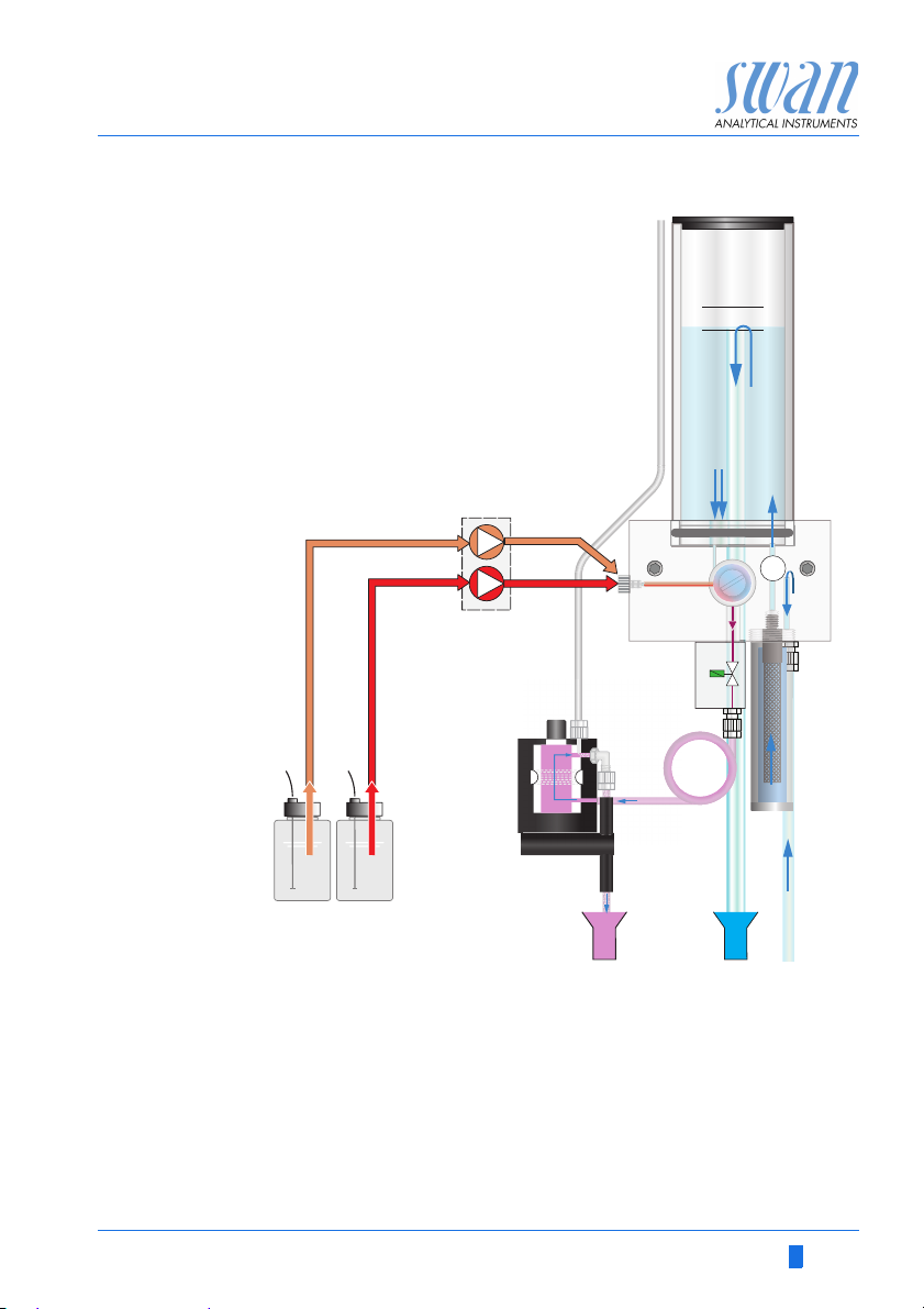
Fluidics The sample flows through the sample inlet [P] and the inlet filter [H]
into the constant head [A]. Adjust the flow regulating valve [F] so
that always a small part of the sample flows through the overflow
tube [B] into the constant head drain [O].
Total chlorine 1 Here the reagents [L] and [M] are added. Sample and reagent flow
Total chlorine 2 To ensure the necessary reaction time of 2 min. for the determina-
through the photometer [J] and total chlorine 1 is measured.
tion of total chlorine 2, the sample flow is stopped by the solenoid
valve [G]. After the time has elapsed, total chlorine 2 is measured
and the solenoid valve [G] opens again.
After the measurement the sample flows through the outlet of the
photometer where it will be aerated through air inlet [I] to generate
bubbles. Then the sample flows through the bubble detector [K]
into the photometer drain [N].
12 A-96.250.631 / 280219
AMI Codes-II TC
Level
E
B
C
A
D
G
H
I
L
J
K
M
NPO
F
Product Description
A
Constant head
B
Overflow tube
C
Photometer inlet
D
Peristaltic pump
E
Mixing chamber
F
Flow regulating valve
G
Solenoid valve
H
Inlet Filter
A-96.250.631 / 280219 13
I
Photometer air inlet
J
Photometer
K
Air bubble detector
L
Reagent Oxycon on-line DPD
M
Reagent Oxycon on-line Buffer
N
Photometer drain
O
Constant head drain
P
Sample inlet

AMI Codes-II TC
0
L
M
120 sec
120 sec180 sec
tc1 tc2
G
G
tc1 tc2
G
G
Product Description
Time
interval of a
measurement
The measuring interval can be set between 3 and 60 minutes. The
time sequence of a measurement with a measuring interval of
5 min is shown in the diagram below.
The blue bar represents the flowing sample. A short time before the
measurement starts, a zero point measurement is performed. Then
the peristaltic pump starts and a small portion of the reagents [L]
and [M] is pumped into the mixing chamber.
A short time after, when the mixture is in the photometer, the solenoid valve [G] is energized and the sample flow through the potometer is stopped. Immediately after that, the total chlorine 1 is
measured. After 120 sec. the total chlorine 2 is measured. After the
measurement is finished, the solenoid valve [G] is de-energized
and sample flows through the photometer until the next measurement starts.
14 A-96.250.631 / 280219

AMI Codes-II TC
Product Description
2.1. Instrument Specification
Power Supply Voltage:
Power consumption:
Electronics Aluminium with a protection degree of IP 66 / NEMA 4X
housing Ambient temperature:
Limit range of operation:
Storage and transport:
Humidity:
Display:
Sample
requirements
On-site The analyzer site must permit connections to:
requirements Sample inlet:
Flow rate:
Temperature:
Inlet pressure:
Outlet pressure:
NOTICE: No oil, no grease, no sand.
Sample outlet:
100–240 VAC (± 10%)
50/60 Hz (± 5%)
or 24 VDC (± 10%)
max. 30 VA
-10 to +50 °C
-25 to +65 °C
-30 to +85 °C
10–90% rel., non condensing
backlit LCD, 75 x 45 mm
min. 10 l/h
5 - 50 °C (41 - 122 °F)
0.15 - 2 bar (2 - 28 PSI)
pressure free
Tube 6 x 8 mm
2 Drains, 1/2” hose nozzle for flexible
tube diam. each 20x15 mm
A-96.250.631 / 280219 15

AMI Codes-II TC
AMI Codes II TC
824 mm / 32
7
/
16
”
412 mm / 16 ½ ”
850 mm / 33½”
13 mm / ½”
400 mm / 15¾”
374 mm / 14¾”
13 mm / ½”
6 x dia. 6.5 mm / ¼”
30 mm / 1 ”
3
16
/
Product Description
Dimensions Panel:
Mounting hole distance
Screws:
Weight:
400x850x200 mm
374x824
5 mm or 6 mm diameter
12.0 kg / 26.5 lbs without reagents and
sample water
17.0 kg / 37.5 lbs with reagents and
sample water
16 A-96.250.631 / 280219

AMI Codes-II TC
A
B
C
D
E
F
G
H
I
J
K
L
M
N
O
Product Description
2.2. Instrument Overview
A
Panel
B
Transmitter
C
Peristaltic pump
D
Reagent Oxycon on-line DPD
E
Reagent Oxycon on-line Buffer &
Reagent Oxycon on-line KI
F
Temperature sensor
A-96.250.631 / 280219 17
G
pH sensor
H
Constant head
I
Flow regulating valve
J
Sample inlet
K
Inlet filter
L
Photometer
M
Air bubble detector
N
Constant head drain
O
Photometer drain

AMI Codes-II TC
Installation
3. Installation
3.1. Installation Check List
Check Instrument’s specification must conform to the National Electrical
Code, all state and local codes, and all plant codes and standards
for electrical equipment.
On-site requirements
Installation Mount the instrument in vertical position.
Electrical Wiring Do not switch on the Instrument until all electrical connections are
If ordered:
Option pH
Reagents Prepare reagents. See Refill or replace Reagents, p. 46.
Power-up Perform exactly in this order:
Instrument
Setup
Run-in period Let the instrument run continuously for 1 h.
pH sensor
calibration
100– 240 VAC ( 10%), 50/60 Hz ( 5%) or 24 VDC (±10%),
isolated power outlet with ground connection and 30 VA.
Sample line with min. 10 l/h and 0.15 – 2 bar.
Waste line with atmospheric drain.
Display should be at eye-level.
Mount the filter, filter vessel, and constant head cover. Connect the
sample and waste line. See Connecting Sample and Waste, p. 19
made.
Connect all external devices like limit switches, current loops and
pumps.
Connect power cord.
See Electrical Connections, p. 26.
See Install the Option pH, p. 22.
Insert the suction lances.
Close the occlusion frames of the peristaltic pump
Turn on the sample flow and wait until the flow cell is completely
filled
Switch on power.
Start <Fill system> see 4.4., 38
Program all parameters for external devices (interface, recorders,
etc.). Program all parameters for instrument operation (limits,
alarms, measuring interval).
If ordered: Calibrate pH sensor. See Standard pH, p. 53
18 A-96.250.631 / 280219

AMI Codes-II TC
Installation
Process
calibration
3.2. Mounting of Instrument Panel
Mounting
requirements
3.3. Connecting Sample and Waste
Make 3 manual measurements. Use a high quality photometer,
e.g. Chematest from Swan. Calculate the average value and compare this value with the measuring value of the AMI Monitor. If necessary, correct the value. The zero point is done automatically
before each measurement.
The first part of this chapter describes the preparing and placing of
the instrument for use.
The instrument must only be installed by trained personnel.
Mount the instrument in vertical position.
For ease of operation mount it so that the display is at eye
level.
For the installation a kit containing the following installation
material is available:
– 6 Screws 6x60 mm
–6 Dowels
– 6 Washers 6.4/12 mm
The instrument is only intended for indoor installation.
For dimensions see Dimensions, p. 16.
3.3.1 FEP Tube at Sample Inlet
Use plastic tube (FEP, PA, or PE 6 x 8 mm) to connect the sample
line.
Mounting of
SERTO fitting
A-96.250.631 / 280219 19
A
A
B
C
D
Screw connection
B
Compression ferrule
C
Knurled nut
D
Flexible tube

AMI Codes-II TC
A
Installation
3.3.2 FEP Tube at Sample Outlet
WARNING
Risk of water pollution
The drain of the photometer outlet contains DPD.
At no means recirculate it into the water system.
B
Connect the 1/2” tubes [F] to the hose nozzles [E] and place it into
a pressure free drain with sufficient capacity.
A
Tube from photometer
B
C
D
E
F
Drain Photometer
C
Tube from constant head
D
Drain constant head
E
Hose nozzles
F
1/2” tubes
3.4. Installation of Flow Cell
CAUTION
Fragile Part
Handle the constant head tube with care.
To avoid damage during the transport, the constant head tube [C] of
the AMI Codes-II TC is not installed.
20 A-96.250.631 / 280219

AMI Codes-II TC
Level
A
B
E
D
C
Installation
A
Constant head cover
B
Overflow tube
C
Constant head tube
D
Gasket
E
Flow cell block
To install the constant head tube proceed as follows:
A-96.250.631 / 280219 21
1 Unpack the constant head tube [C].
2 Push the constant head tube into the flow cell block [E].
3 Put the constant head cover [A] onto the constant head tube.
4 Check if the overflow tube [B] is aligned with the upper level
mark.

AMI Codes-II TC
B
C
D
A
E
G
F
Installation
3.5. Install the Option pH
3.5.1 pH as Option ex works
If the pH option was ordered with the AMI Codes-II TC, the pH sensor cable as well as the temperature sensor are already connected
to the AMI transmitter.
A
Connector cap
B
Connector
C
pH Sensor
D
Temperature sensor
E
Constant head cover
F
Protective cap
G
Constant head
1 Carefully pull off the protective cap [F] from the pH sensor [C]
by turning it clockwise.
2 Store the protective cap in a safe place.
3 Rinse the pH sensor tip with clean water.
4 Insert the pH sensor into one of the holes in the constant head
cover [E].
5 Insert temperature sensor [D] into the small hole.
6 Remove the connector cap from the connector of the pH sen-
sor. Store it in safe place.
7 Screw the connector [B] onto the pH sensor.
22 A-96.250.631 / 280219

AMI Codes-II TC
ABC
FE D
Installation
3.5.2 pH Option as Retrofit Kit
A
2 Clamps with screws
B
pH sensor
C
Sensor cable
A-96.250.631 / 280219 23
D
E
F
Frontend PCB
Temperature sensor
Short overflow tube

AMI Codes-II TC
Level
A
B
C
D
Installation
WARNING
Risk of electrical shock.
Do not perform any work on electrical components if the transmitter is switched on. Failure to follow safety instructions could
result in serious injury or death.
Always turn off AC power before manipulating electric parts.
1 Screw the clamps for calibration solution onto the panel. Use
the already drilled holes [A].
AMI Codes-II
2 Stop sample flow. Wait until flow cell is empty.
3 Switch off the AMI transmitter (disconnect power).
A
A
Constant head cover
B
Constant head tube
C
Short overflow tube
D
Flow cell block
4 Remove the constant head cover [A] and the constant head
tube [B] from the flow cell block [D].
5 Insert the short overflow tube [C] into the outlet hole leading to
the photometer.
6 Install the constant head tube and the constant head cover.
24 A-96.250.631 / 280219

AMI Codes-II TC
AB C
Installation
7 Open the cover of the AMI transmitter housing.
8 Install the front end PCB.
9 Feed the cable of the pH sensor through one of the cable
glands (see Cable thicknesses, p. 26) into the AMI transmitter
housing.
10 Connect it to the BNC socket.
11 Feed the cable of the Temperature sensor through one of the
cable glands into the AMI transmitter housing.
12 Connect the temperature sensor cable to the plug as follows:
Terminal 19: line
Terminal 20: shield.
13 Close the cover of the AMI transmitter housing.
14 Turn on sample flow and wait until flow cell has been filled com-
pletely.
15 Switch power ON. The instrument automatically detects the
front end PCB during start-up.
A
Front end PCB
B
pH sensor plug
C
Temperature sensor plug
A-96.250.631 / 280219 25

AMI Codes-II TC
Installation
3.6. Electrical Connections
WARNING
Risk of electrical shock.
Do not perform any work on electrical components if the transmitter is switched on. Failure to follow safety instructions could
result in serious injury or death.
Always turn off AC power before manipulating electric parts.
Grounding requirements: Only operate the instrument from
an power outlet which has a ground connection.
Make sure the power specification of the instrument corre-
sponds to the power on site.
Cable
thicknesses
In order to comply with IP66, use the following cable thicknesses
ABC
PG 11 cable gland: cable Ø
A
B
PG 7 cable gland: cable Ø
C
PG 9 cable gland: cable Ø
NOTICE: Protect unused cable glands
Wire For Power and Relays: Use max. 1.5 mm
stranded wire with end sleeves.
For Signal Outputs and Input: Use 0.25 mm
stranded wire with end sleeves.
outer
3–6.5 mm
outer
4–8 mm
outer
5–10 mm
2
/ AWG 14
2
/ AWG 23
26 A-96.250.631 / 280219

AMI Codes-II TC
Installation
WARNING
External Voltage.
External supplied devices connected to relay 1 or 2 or to the
alarm relay can cause electrical shocks
Make sure that the devices connected to the following con-
tacts are disconnected from the power before resuming installation.
– relay 1
– relay 2
– alarm relay
WARNING
To prevent from electrical shock, do not connect the instrument
to the power unless the ground wire (PE) is connected.
Do not connect unless specifically instructed to do so.
WARNING
The mains of the AMI Transmitter must be secured by a main
switch and appropriate fuse or circuit breaker.
A-96.250.631 / 280219 27

AMI Codes-II TC
Installation
3.6.1 Connection Diagram
CAUTION
Use only the terminals shown in this diagram, and only for the
mentioned purpose. Use of any other terminals will cause short
circuits with possible corresponding consequences to material
and personnel.
28 A-96.250.631 / 280219

AMI Codes-II TC
A
B
C
D
Installation
3.6.2 Power Supply
WARNING
Risk of electrical shock
Do not perform any work on electrical components if the transmitter is switched on. Failure to follow safety instructions could
result in serious injury or death.
Always turn off AC power before manipulating electric parts.
Installation and maintenance of electrical parts must be per-
formed by professionals.
A
Power supply connector
B
Neutral conductor, Terminal 2
C
Phase conductor, Terminal 1
D
Protective earth PE
NOTICE: The protective earth wire (Ground) has to be
connected to the grounding terminal.
Installation
requirements
A-96.250.631 / 280219 29
The installation must meet the following requirements.
Fuse 1.6 AT
Mains cable to comply with standards IEC 60227 or IEC
60245; flammable rating FV1
Mains equipped with an external switch or circuit-breaker
– near the instrument
– easily accessible to the operator
– marked as interrupter for AMI Codes-II TC
AMI Codes-II TC
10
12
11
0V
1)
10
12
11
0V
Installation
3.7. Input
NOTICE: Use only potential-free (dry) contacts.
The total resistance (sum of cable resistance and resistance of
the relay contact) must be less than 50 Ω.
Terminals 30 and 31
For programming see Program Overview, p. 74.
3.8. Relay Contacts
3.8.1 Alarm Relay
NOTICE: Max. load 1 A / 250 VAC
Alarm output for system errors.
Error codes see Troubleshooting, p. 65.
NOTICE: With certain alarms and certain settings of the AMI
transmitter the alarm relay does not switch. The error, however,
is shown on the display.
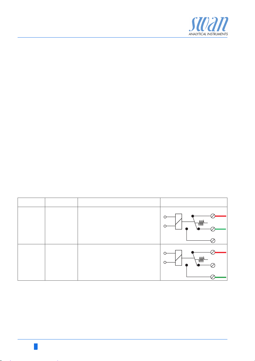
Ter min als Description Relay connection
1)
NC
Normally
Closed
10/11 Active (opened) during normal
operation.
Inactive (closed) on error and
loss of power.
12/11 Active (closed) during normal
operation.
Inactive (opened) on error and
loss of power.
1) usual use
NO
Normally
Open
30 A-96.250.631 / 280219
AMI Codes-II TC
6
0V
7
6
0V
7
A
B
Installation
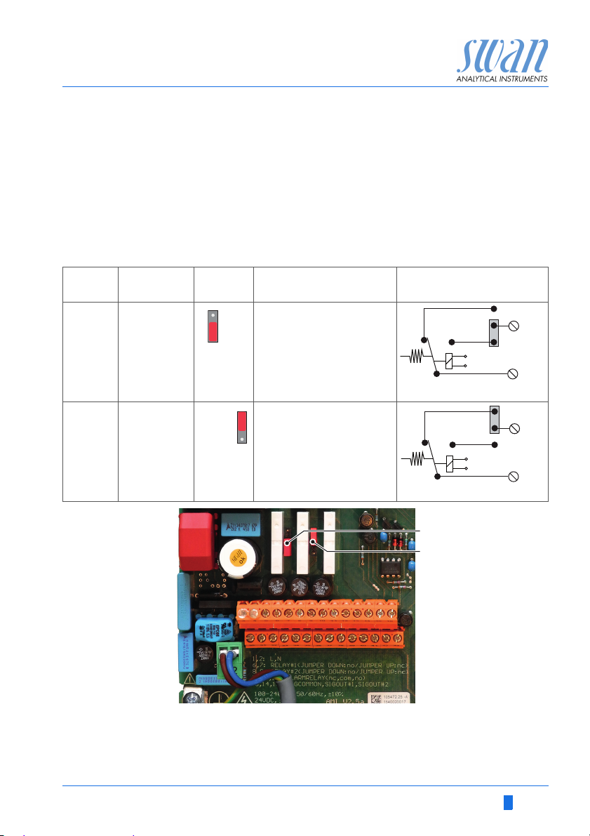
3.8.2 Relay 1 and 2
NOTICE: Max. load 1 A/250 VAC
Relay 1 and 2 can be configured as normally open or as normally
closed. Standard for both relays is normally open. To configure a
Relay as normally closed, set the jumper in the upper position.
NOTICE: Some error codes and the instrument status may
influence the status of the relays described below.
Relay
config. Terminals
Normally
Open
Normally
Closed
6/7: Relay 1
8/9: Relay 2
6/7: Relay 1
8/9: Relay 2
Jumper
pos. Description Relay configuration
Inactive (opened) during
normal operation and
loss of power.
Active (closed) when a
programmed function is
executed.
Inactive (closed) during
normal operation and
loss of power.
Active (opened) when a
programmed function is
executed.
ABJumper set as normally open (standard setting)
Jumper set as normally closed
For programming see Program Overview, p. 74, Menu Installation
A-96.250.631 / 280219 31
AMI Codes-II TC
A
BC
DE
Installation
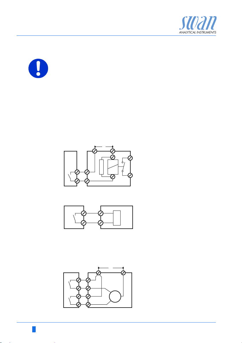
CAUTION
Risk of damage of the relays in the AMI Transmitter due to
heavy inductive load.
Heavy inductive or directly controlled loads (solenoid valves,
dosing pumps) may destroy the relay contacts.
To switch inductive loads > 0.1 A use an AMI relay box avail-
able as an option or suitable external power relays.
Inductive load Small inductive loads (max 0.1 A) as for example the coil of a pow-
Resistive load Resistive loads (max. 1 A) and control signals for PLC, impulse
Actuators Actuators, like motor valves, are using both relays: One relay con-
er relay can be switched directly. To avoid noise voltage in the
AMI Transmitter it is mandatory to connect a snubber circuit in parallel to the load.
A snubber circuit is not necessary if an AMI relaybox is used.
A
AC or DC power supply
B
AMI Transmitter
C
External power relay
D
Snubber
E
Power relay coil
pumps and so on can be connected without further measures
A
AB
C
tact is used for opening, the other for closing the valve, i.e. with the
2 relay contacts available, only one motor valve can be controlled.
Motors with loads bigger than 0.1 A must be controlled via external
power relays or an AMI relay box.
A
BC
AMI Transmitter
B
PLC or controlled pulse pump
C
Logic
A
AC or DC power supply
B
AMI Transmitter
C
Actuator
M
32 A-96.250.631 / 280219
AMI Codes-II TC
Installation
3.9. Signal Outputs
3.9.1 Signal Output 1 and 2 (current outputs)
NOTICE: Max. burden 510 Ω
If signals are sent to two different receivers, use signal isolator
(loop isolator).
Signal output 1: Terminals 14 (+) and 13 (-)
Signal output 2: Terminals 15 (+) and 13 (-)
For programming see Program Overview, p. 74, Menu Installation
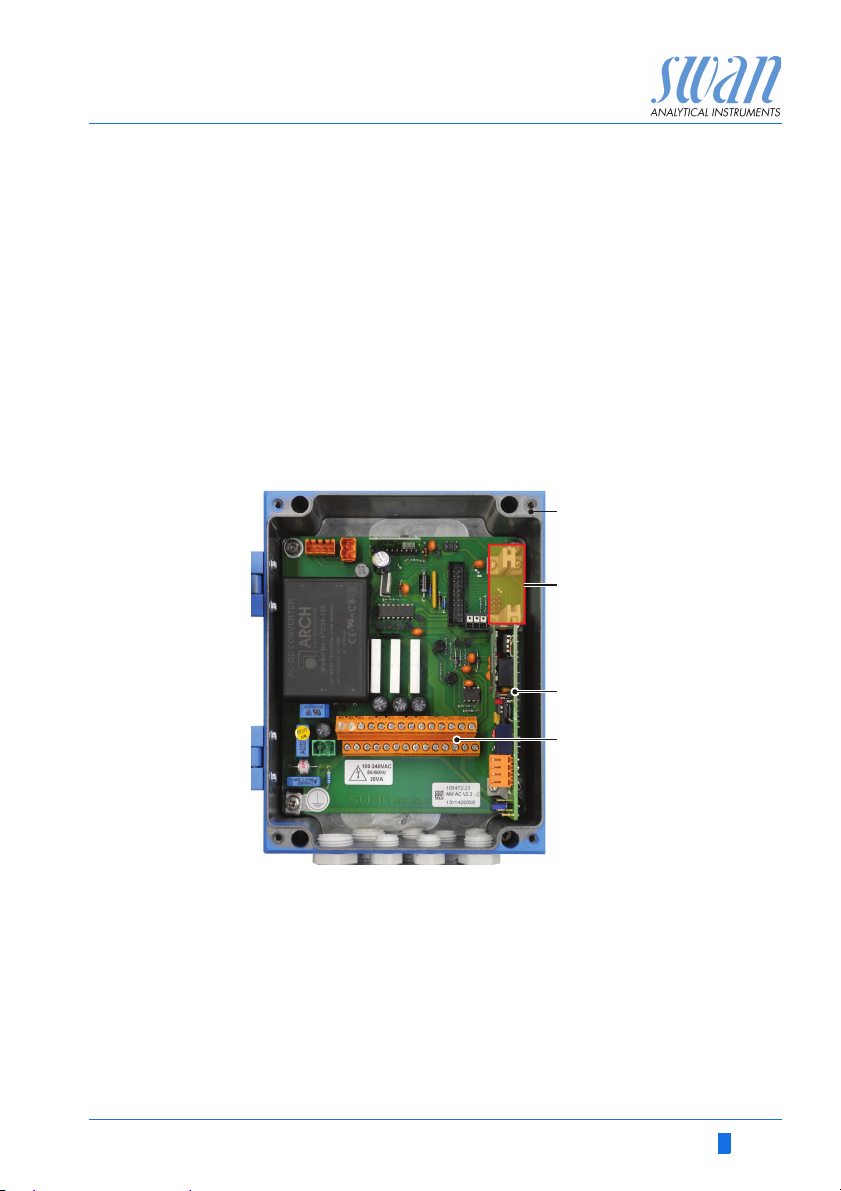
3.10 Interface Options
A
AMI Transmitter
A
B
Slot for interfaces
C
Frontend PCB
D
Screw terminals
B
C
D
The slot for interfaces can be used to expand the functionality of
the AMI instrument with either:
Third signal output
a Profibus or Modbus connection
a HART connection
a USB Interface
A-96.250.631 / 280219 33
AMI Codes-II TC
A
Installation
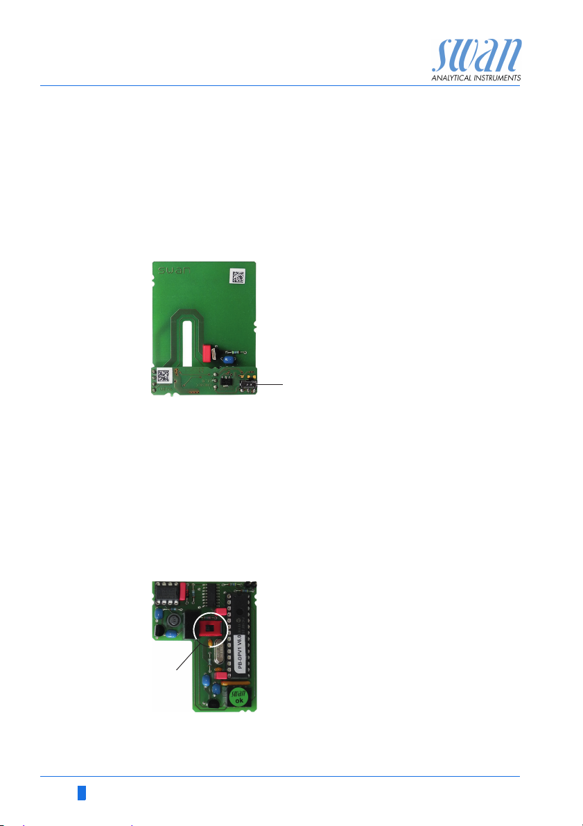
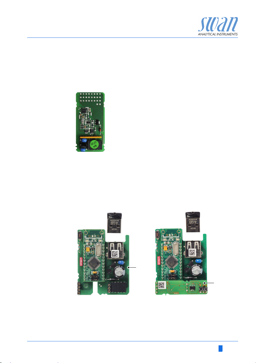
3.10.1 Signal Output 3
Terminals 38 (+) and 37 (-).
Requires the additional board for the third signal output 0/4 – 20 mA.
The third signal output can be operated as a current source or as a
current sink (switchable via switch [A]). For detailed information see
the corresponding installation instruction.
NOTICE: Max. burden 510 Ω.
Third signal output 0/4 - 20 mA PCB
A Operating mode selector switch
3.10.2 Profibus, Modbus Interface
Terminal 37 PB, Terminal 38 PA
To connect several instruments by means of a network or to config-
ure a PROFIBUS DP connection, consult the PROFIBUS manual.
Use appropriate network cable.
NOTICE: The switch must be ON, if only one instrument is
installed, or on the last instrument in the bus.
OFF
ON
A
Profibus, Modbus Interface PCB (RS 485)
A On - OFF switch
34 A-96.250.631 / 280219
AMI Codes-II TC
A
B
Installation
3.10.3 HART Interface
Terminals 38 (+) and 37 (-).
The HART interface PCB allows for communication via the HART
protocol. For detailed information, consult the HART manual.
HART Interface PCB
3.10.4 USB Interface
The USB Interface is used to store Logger data and for Firmware
upload. For detailed information see the corresponding installation
instruction.
The optional third signal output 0/4 – 20 mA PCB [B] can be
plugged onto the USB interface and used in parallel.
USB Interface
A USB interface PCB
B Third signal output 0/4 - 20 mA PCB
A-96.250.631 / 280219 35
AMI Codes-II TC
A
B
D
C
Instrument Setup
4. Instrument Setup
After installation according to checklist proceed as follows:
4.1. Prepare Reagents
1 Prepare reagents. See Refill or replace Reagents, p. 46.
2 Insert the suction lances into the canisters.
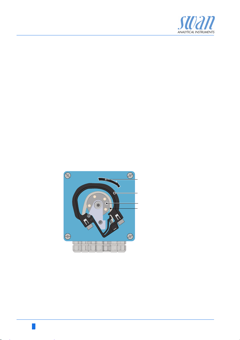
4.2. Peristaltic Pump
The instrument is delivered with opened occlusion frames.
1 Activate the peristaltic pump tubes by closing the occlusion
frames [B].
A
Turn to lock
B
Occlusion frame
C
Rotor
D
Pump tube
36 A-96.250.631 / 280219

AMI Codes-II TC
Level
A
B
C
D
E
F
Instrument Setup
4.3. Establish Sample Flow
WARNING
Water pollution
The drain of the photometer outlet contains DPD.
At no means recirculate it into the water system.
A
Cover
B
Constant head tube
C
Flow cell block
D
Flow regulating valve
E
Filter
F
Filter vessel
1 Open the flow regulating valve (D) and wait until the flow cell is
completely filled.
2 Switch on power.
3 Adjust the sample flow so that always a small part of the sample
drains off through the overflow tube.
4 Start <Fill system>, see Fill or Flush Reagent System, p. 38.
A-96.250.631 / 280219 37
AMI Codes-II TC
3.2.2
Fill System
Verification
Service
Cleaning
3.2.2.5
Fill System
Progress
<Enter> to stop
3.2.2.5
Fill System
Progress
Done
Instrument Setup
4.4. Fill or Flush Reagent System
Fill or flush the reagent tubing:
upon the initial instrument setup,
after refilling the reagent canisters,
before a system shut-down to flush the system with deminer-
alized water until no more reagent is left in the system.
Navigate to menu< Maintenance /
Service/ Fill system>.
Press [Enter].
The peristaltic pump is activated for
1.5 minutes.
Press [Exit] 4 x to go back to the operating mode.
1 Check tubing and flow cell for leaks and repair if necessary.
2 Let the instrument run continuously for 1 hour.
4.5. Programming
Programming Program all parameters for external devices (interface, recorders,
etc.)
Program all parameters for instrument operation (disinfectant, limits, alarms).
Program the DPD value of the Verikit in menu <Installation/
Sensors/Ref. Verification>.
If pH option is installed, program the two buffers you want to use for
calibration in menu <Installation/Sensors/Standards>.
See Program List and Explanations, p. 80.
38 A-96.250.631 / 280219

AMI Codes-II TC
Instrument Setup
4.6. Calibration
1 Calibrate pH sensor (if option pH is installed).
See Standard pH, p. 53.
2 Perform process calibration.
See Process Calibration of tc 2, p. 51
If ordered:
Calibration of
pH sensor
Process DIS Let the instrument run for 1 h.
The instrument should be operating for 1h before performing a pH
calibration.
Use CHEMATEST (or equivalent photometer) to determine the
sample disinfectant concentration. Take the sample directly from
the flow cell. Determine the sample disinfectant value by 3 manual
DPD measurements. Calculate the average value. Compare this
value to the value, indicated by the AMI.
Keep in mind the accuracy of your manual measurement. Only correct the instrument if the difference is significant.
Perform process DIS if necessary. See chapter Calibration, p. 51
for details.
A-96.250.631 / 280219 39

AMI Codes-II TC
25.4°C
RUN
9 l/h
14:10:45
R1
0.22 ppm
0.26 ppm
R2
1
Installation
Operation
Diagnostics
Messages
Maintenance
Main Menu
Enter
Exit
Operation
5. Operation
5.1. Keys
A to exit a menu or command (rejecting any changes)
to move back to the previous menu level
B to move DOWN in a menu list and to decrease digits
C to move UP in a menu list and to increase digits
D to open a selected sub-menu
to accept an entry
BCDA
Exit Enter
Program
Access, Exit
40 A-96.250.631 / 280219

AMI Codes-II TC
RUN
47 B/s 2.68 °C
12:56:02
R1
R2
ppm
0.22
tc1
ppm
0.26
tc2
AB C D
F
E
G
H
K
I
Operation
5.2. Display
A RUN normal operation
HOLD input closed or cal delay: Instrument on hold (shows
OFF input closed: control/limit is interrupted (shows status
B ERROR Error
C Reagent low, indicates remaining reagents in% (17 % = 340 ml)
D Keys locked, transmitter control via Profibus
E Time
F Process values
G Sample Temperature
H Cleaning solution low, indicates remaining cleaning solution in %
I Sample flow in B/s
K Relay status
status of signal outputs).
of signal outputs).
Fatal Error
Relay status, symbols
upper/lower limit not yet reached
upper/lower limit reached
control upw./downw. no action
control upw./downw. active, dark bar indicates control intensity
A-96.250.631 / 280219 41
motor valve closed
motor valve: open, dark bar indicates approx. position
timer
timer: timing active (hand rotating)

AMI Codes-II TC
1
Messages
Operation
Maintenance
Diagnostics
Main Menu
Installation
1.1
Pending Errors
Messages
Maintenance List
Message List
2.1
Interface
I/O State
Sample
Identification
Sensors
Diagnostics
3.1
Calibration
Simulation
Maintenance
Set Time 23.09.06 16:30:00
Service
4.1
Logger
Relay Contacts
Sensors
Operation
5.1
Interface
Miscellaneous
Relay Contacts
Sensors
Signal Outputs
Installation
Operation
5.3. Software Structure
Menu Messages 1
Reveals pending errors as well as an event history
(time and state of events that have occurred at an
earlier point of time).
It contains user relevant data.
Menu Diagnostics 2
Provides user relevant instrument and sample data.
Menu Maintenance 3
For instrument calibration, relay and signal output
simulation, and to set the instrument time.
It is used by the service personnel.
Menu Operation 4
User relevant parameters that might need to be
modified during daily routine. Normally password
protected and used by the process-operator.
Subset of menu 5 - Installation, but process-related.
Menu Installation 5
For initial instrument set up by SWAN authorized
person, to set all instrument parameters. Can be
protected by means of password.
42 A-96.250.631 / 280219

AMI Codes-II TC
5.1.2
Sensors
Sensor type FOME
Temperature NT5K
Standards
Disinf. Free chlorine
4.4.1
Logger
Log interval 30 min
Clear logger no
4.1.3
Logger
Clear logger no
Log interval 30min
1 Hour
Interval.
5 min
30 min
10 min
4.1.3
Logger
Log interval 10 min
Clear logger no
4.1.3
Logger
Log interval
Clear logger no
No
Save ?
Yes
5.3.1.1.1
Alarm High 5.00 ppm
Total chlorine 1
Alarm Low 0.00 ppm
Hysteresis 1.00 ppm
Delay 5 Sec
5.3.1.1.1
Total chlorine 1
Alarm Low 0.00 ppm
Hysteresis 1.00 ppm
Delay 5 Sec
Alarm High 2.00 ppm
Operation
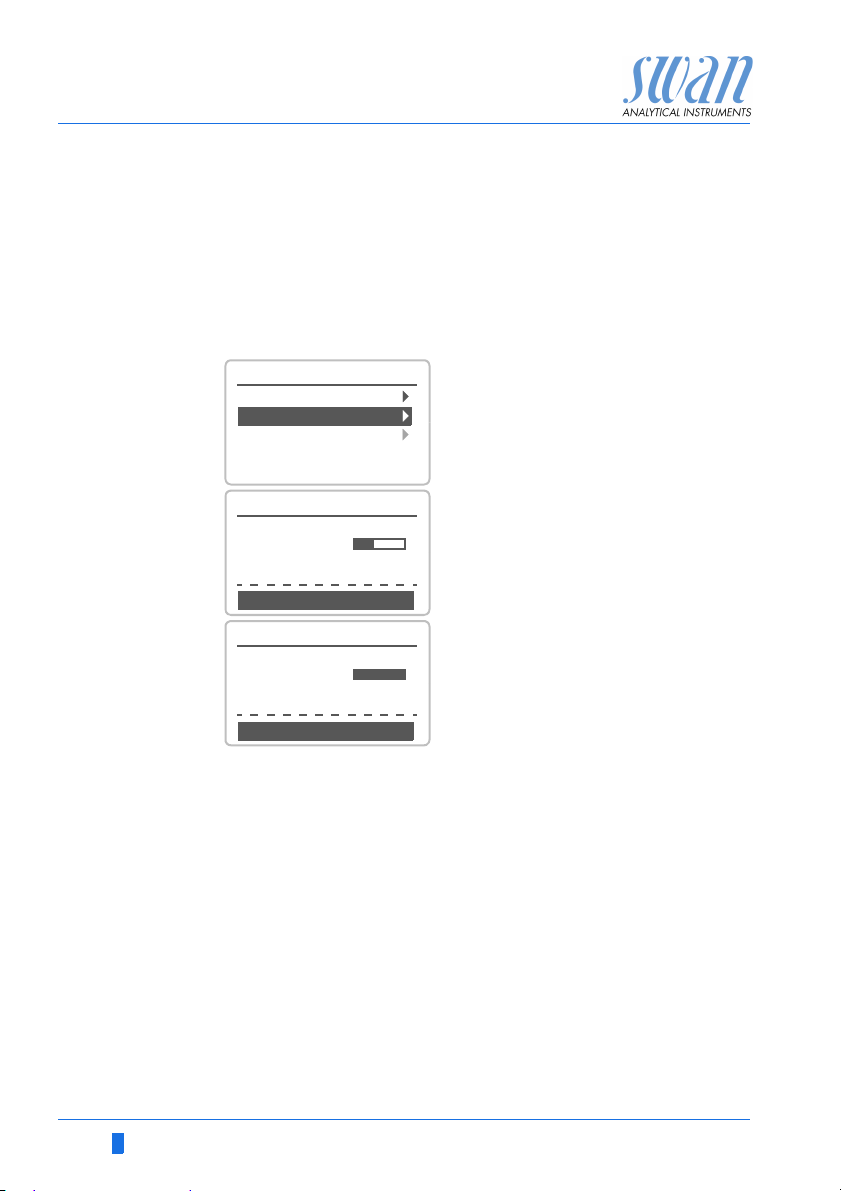
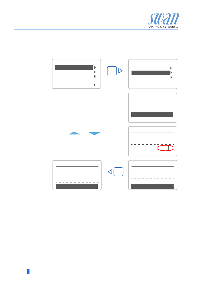
5.4. Changing Parameters and values
Changing
parameters
The following example shows how to change the logger interval:
1 Select the parameter you want to
change.
2 Press [Enter].
3 Press [ ] or [ ] key to
highlight the required parameter.
4 Press [Enter] to confirm the selec-
tion or [Exit] to keep the previous
parameter).
The selected parameter is
highlighted but not saved yet.
5 Press [Exit].
Yes is highlighted.
6 Press [Enter] to save the new pa-
rameter.
The system reboots, the new
parameter is set.
Changing
values
A-96.250.631 / 280219 43
1 Select the value you want to
change.
2 Press [Enter].
3 Set required value with [ ] or
[ ] key.
4 Press [Enter] to confirm the new
value.
5 Press [Exit].
Yes is highlighted.
6 Press [Enter] to save the new val-
ue.

AMI Codes-II TC
Maintenance
6. Maintenance
6.1. Maintenance Schedule
WARNING
Stop operation before maintenance.
Stop sample flow.
Shut off power of the instrument.
Daily (dirty water)
up to every
2 weeks (clean
water)
Every 4–6 weeks Clean reagent canisters and prepare new reagents.
Monthly Recommendation: Check photometer with verification kit
Yearl y Exchange reagent pump tubes.
By occurrence E020, FOME dirty: Cleaning the Photometer, p. 55
If pH option is installed:
Weekly Perform a process calibration, see Process pH, p. 51.
Every 2 months: Perform a standard calibration, see Standard pH, p. 53.
Check sample supply for dirt.
Clean all filters and strainers, if necessary.
Clean AMI Codes protection filter, if necessary.
Check sample flow (see also Troubleshooting, p. 65).
Let instrument run for 1 h. Make 3 manual measurements. Compare average value to displayed value. If necessary, perform process calibration.
Verification, p. 50.
E065, Reagents low: Refill or replace Reagents, p. 46
E022, Reagent empty: Refill or replace Reagents, p. 46
44 A-96.250.631 / 280219

AMI Codes-II TC
Maintenance
6.2. Stop of Operation for Maintenance
1 Put the suction lances into a bucket with clean water.
2 Start <Fill system>.
The reagent tubes are flushed with water.
3 Remove the suction lances from the water.
4 Start <Fill system> again.
The water will be pumped out of the reagent tubes.
5 Stop sample flow.
6 Wait until the flow cell is empty.
7 Shut off power of the instrument.
If pH option is installed:
8 Remove the pH sensor [A] from the flow cell.
9 Fill the protective cap [B] with water.
10 Put the protective cap onto the sensor tip.
ABpH sensor
Protective cap
A
B
A-96.250.631 / 280219 45
AMI Codes-II TC
Maintenance
6.3. Refill or replace Reagents
The liquid level in canister 2 is monitored. The following messages
are displayed:
canister almost
empty
canister empty Error E022 - Reagent empty
NOTICE: Before refilling the reagents, rinse the canisters with
demineralized water.
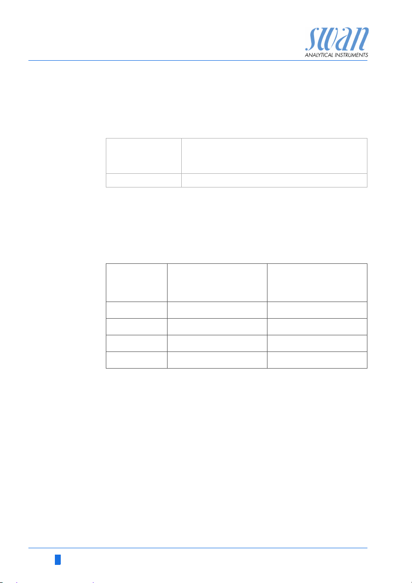
Reagent
consumption
The reagent consumption depends on the selected measuring interval and on the selected operating mode (measuring range: Standard / Extended). Below you will find some examples:
Maintenance E065 - Reagents low and the
remaining reagent volume in %
(starting at 17 % = 340 ml).
Measuring
interval
3 minutes 13–19 days 8–11 days
5 minutes 22–32 days 13–19 days
10 minutes 44–63 days 26– 38 days
20 minutes 88–126 days 53–76 days
The provided reagent set is sufficient for 8 canister fillings.
Duration per canister
(measuring range:
standard)
Duration per canister
(measuring range:
extended)
46 A-96.250.631 / 280219
AMI Codes-II TC
Maintenance
WARNING
Health hazard
Some reagents can cause severe burns or eye damage.
For safe handling of the reagents you must read and under-
stand the Material Safety Data Sheets (MSDS), see Material
Safety Data sheets, p. 100
Oxycon On-line DPD
WARNING
Severe eye irritation and severe skin irritation.
Concentrated Oxycon On-line DPD contains more than 10%
mineral acids.
Do not swallow.
Avoid any contact with eyes and skin.
Wear protective goggles,
Wear protective gloves.
IF IN EYES: Rinse cautiously with water for several minutes.
Remove contact lenses, if present and easy to do. Continue
rinsing.
Immediately call a POISON CENTER or doctor/ physician.
Oxycon On-line Buffer
Contains citric acid potassium salt, do not swallow.
Oxycon On-line KI
CAUTION
Severe eye irritation and skin irritation.
This product is corrosive and causes severe burns.
Harmful if swallowed.
Avoid any contact with eyes and skin
IF IN EYES: Rinse cautiously with water for several minutes.
Remove contact lenses, if present and easy to do. Continue
rinsing.
A-96.250.631 / 280219 47
AMI Codes-II TC
OXYCON ON-LINE
DPD-Reagenz
DPD Réactif
DPD Reagent
2L
OXYCON ON-LINE
Pufferlösung
Tampon
Buffer Solution
2L
A
B
C
E
D
G
F
Maintenance
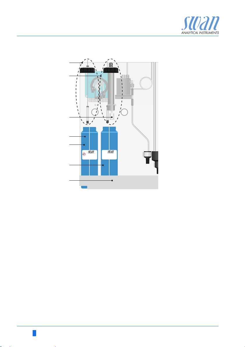
Canister set up
A
Suction lance without
level detector
(canister 1)
B
Suction lance with
level detector
(canister 2)
C
Level detector
D
2 L mark
E
Canister 1:
Oxycon on-line DPD
F
Canister 2:
Oxycon on-line Buffer
G
Holder
48 A-96.250.631 / 280219

AMI Codes-II TC
Maintenance
6.3.1 Reagents for Measuring Total Chlorine
Reagents needed:
1 x 50 ml of Oxycon On-line DPD
1 x 240 gr of Oxycon On-line Buffer
1 x 60 gr of Reagent Oxycon On-line KI
4 liters demineralized water
Prepare
Oxycon
On-line DPD
Prepare
Oxycon
On-line Buffer
& KI
1 Rinse the canister [E] labelled OXYCON ON LINE DPD-Re-
agent with demineralized water.
2 Fill the canister up to the 2 liter mark with demineralized water.
3 Slowly pour the content of one bottle of concentrate Oxycon
On-line DPD (50 ml) into the canister.
Avoid splashing!
4 Close the canister with the screw cover and tighten it well.
5 Mix the demineralized water and the reagents well.
6 Put the canister [E] into the holder [G].
7 Remove the screw cover, insert suction lance [A] and tighten
the screw cover.
1 Rinse the canister [F] labelled “OXYCON ON LINE Buffer” solu-
tion with demineralized water.
2 Fill the canister up to the 2 liter mark with demineralized water.
3 Slowly pour the content of one bag of Oxycon On-line Buffer
into the canister.
Avoid splashing!
4 Add the content of one bag Oxycon On-line KI to the same can-
ister.
5 Close the canister with the screw cover and tighten it well.
6 Mix the demineralized water and the reagents well.
7 Put the canister [F] into the holder [G].
8 Remove the screw cover and insert suction lance [B]. Tighten
the screw cover.
9 Fill reagent system. See Fill or Flush Reagent System, p. 38.
A-96.250.631 / 280219 49

AMI Codes-II TC
Maintenance
6.4. Verification
The “Verification kit for AMI Photometer” is available as
an accessory. An optical window with a precisely determined absorbance value is placed into the light beam
of the photometer. The actual measured absorbance
will be compared to the reference value labeled on
each kit.
Set reference
value:
Verification
procedure:
Verification
history:
Prior to performing the verification the DPD reference value, e.g.
0.255, needs to be set in menu 5.1.4
<Installation>\<Sensors>\<Ref. Verification>.
Basically follow the dialog in menu 3.2.1
<Maintenance>\<Service>\<Verification>.
NOTICE: Start any time, if a measuring cycle is in progress wait
for next prompt.
1 Stop sample flow by closing regulating valve. Wait for next
prompt: Constant head will be drained and an automatic zero
will be defined.
2 Open cuvette of the photometer and insert the verification filter.
<Enter> to continue.
3 Align the triangle shape either to the front or backside and ad-
just for minimal absorbance (see AMI Display).
4 Press <Enter> to save the verification measurement. The verifi-
cation is successful if the difference is within the limits. <Enter>
to continue.
5 Remove filter, close cuvette and open regulating valve. <Enter>
to finish and <Exit> to the main display.
Can be reviewed in menu 2.2.1.5
<Diagnostics>\<Sensors>\<Photometer>\<Ver. History>
50 A-96.250.631 / 280219

AMI Codes-II TC
3.1.1
Total chlorine 2
Calibration
Process pH
Standard pH
3.1.1.4
Total chlorine 2
Current Value x.xx ppm
Slope x.xxx
Save <Enter>
Process Value x.xx ppm
3.1.1.4
Total chlorine 2
Current Value x.xx ppm
Slope x.xxx
Save <Enter>
Process Value x.xx ppm
3.1.1.5
Total chlorine 2
Current Value x.xx ppm
Slope x.xxx
Calibration Successful
Maintenance
6.5. Calibration
Process
Calibration
of tc 2
NOTICE: Perform process calibration for total chlorine only if:
• the sample concentration is close to the desired process
value (stable value)
• you are sure that the reagents are mixed completely and
correctly
• if the difference to the manual measurement is significant.
• Keep in mind the accuracy of your manual measurement.
Use CHEMATEST (or equivalent photometer) to determine the
sample disinfectant concentration. Determine the sample disinfectant value by 3 manual DPD measurements. Calculate the average
value. Compare this value to the value indicated by the AMI transmitter.
Enter
Enter the correct value
with the [ ] or [ ]
key.
Process pH Use a Chematest photometer (or equivalent) to determine the sam-
A-96.250.631 / 280219 51
Press 3 x [Exit]
Possible error message see Calibration Errors, p. 66.
Zero A zero is automatically done before each measurement.
ple pH value.
AMI Codes-II TC
3.1
Calibration
Service
Maintenance
Set Time 01.01.05 16:30:00
Calibration
Simulation
Cleaning
Enter
3.1.2
Calibration
Process pH
Standard pH
Total chlorine 2
Process pH
Offset x mV
Save <Enter>
Process Value 7.78 pH
3.1.2.4
Current Value 7.78 pH
Process pH
Current Value 7.78 pH
Offset x mV
Save <Enter>
Process Value 7.70 pH
3.1.2.4
3.1.2.5
Process pH
Current Value 7.70 pH
Offset y mV
Slope x.xx mV
Calibration successful
3.1.2.5
Process pH
Current Value 7.70 pH
Offset y mV
Process Value 7.70 pH
Save <Enter>
Maintenance
NOTICE: Make sure your reference instrument is calibrated
correctly!
Enter the correct value
with the [ ] or [ ]
key.
Enter
Possible error message see Calibration Errors, p. 66.
52 A-96.250.631 / 280219

AMI Codes-II TC
Enter
Enter
3.1
Calibration
Simulation
Maintenance
Set Time 01.06.04 16:30:00
Fill System
Cleaning
3.1.3
Process pH
Standard pH
Calibration
Total chlorine 2
Maintenance
Standard pH
Display
instructions
1 Navigate to menu <Maintenance> /
<Calibration>.
2 Press [Enter].
3 Remove the pH sensor from the
flow cell.
4 Follow the instructions on the dis-
play.
1 Rinse and dry the pH sensor and put it into standard 1
2 Standard 1, current value (Progress is shown).
3 Rinse and dry the pH sensor and put it in standard 2
4 Standard 2, current value (Progress is shown)
5 Rinse and dry the pH sensor and put it into the flow cell
Possible error message see Calibration Errors, p. 66
A-96.250.631 / 280219 53
AMI Codes-II TC
C
D
E
B
A
Maintenance
6.6. Cleaning the protective Filter
Switch off the instrument according to instructions in Stop of Opera-
tion for Maintenance, p. 45.
Normally the filter in your sample supply line will retain most debris.
If the filter shows deposits, proceed as follows:
A
Flow cell block
B
Flow regulating valve
C
Filter shaft
D
Filter
E
Filter vessel
1 Close the main tap of the sample inlet.
2 Close the flow regulating valve [B].
3 Unscrew the filter vessel [E] from the flow cell block [A].
4 Hold the filter [D] on the shaft [C] and unscrew it from the filter
vessel.
5 Backwash the filter under pressure of tap water.
6 Clean the outside of the filter.
7 Install the filter and the filter vessel again.
8 Open the flow regulating valve.
9 Adjust sample flow with the regulating valve.
54 A-96.250.631 / 280219

AMI Codes-II TC
A
B
C
D
C
Maintenance
6.7. Cleaning the Photometer
Clean the photometer after indication by alarm (E020, FOME dirty).
Switch off the instrument according to instructions in Stop of Opera-
tion for Maintenance, p. 45.
Material Small brush.
Procedure
1 Close the flow regulating valve [A].
2 Wait until the sample flow through the photometer has stopped.
3 Unscrew the cover [B] from the photometer [C].
A
Flow regulating valve
B
Photometer cover
C
Photometer
D
Brush
4 Clean the Photometer with a small brush [D].
A-96.250.631 / 280219 55
5 Screw the cover to the photometer.
6 Open the flow regulating valve.

AMI Codes-II TC
Level
A
B
D
E
C
Maintenance
6.8. Cleaning the Flow Cell
CAUTION
Acrylic glass parts are fragile and scratch-sensitive.
Possible damage of acrylic glass parts due to scrubbing materials.
Never use organic solvents or scrubbing materials to clean
acrylic glass parts.
Use soft detergent and rinse well. Eliminate lime deposits with
a common household deliming agent in standard concentration.
Do not drop the constant head tube
6.8.1 Disassemble the Flow Cell
The flow cell can be disassembled easily. Before disassembling the
flow cell, switch off the instrument according to instructions in Stop
of Operation for Maintenance, p. 45.
A
Constant head cover
B
Overflow tube
C
Constant head tube
D
Flow cell block
E
Flow regulating valve
56 A-96.250.631 / 280219

AMI Codes-II TC
Level
A
B
E
D
C
Maintenance
Cleaning 1 Switch off the instrument according to instructions in Stop of
Operation for Maintenance, p. 45
2 Remove the constant head cover [A].
3 Pull the overflow tube [B] out of the flow cell block [D]
4 Remove the constant head tube [C] from the flow cell block.
5 Clean all acrylic parts with a soft brush (bottle cleaner) and
soapy water.
6 Remove lime deposits with a common household deliming
agent with standard concentrations.
6.8.2 Assemble the Flow Cell
A
Constant head cover
B
Overflow tube
C
Constant head tube
D
Gasket
E
Flow cell block
A-96.250.631 / 280219 57
1 Replace the gasket [D] before reassembling the flow cell.
NOTICE: A film of teflon paste (e.g. Fomblin from Solvay
Solexis) on the gaskets improves tightness and life time.
2 Push the overflow tube [B] through the flow cell block as far as it
reaches the drain.

AMI Codes-II TC
A
B
C
D
Maintenance
3 Install the constant head tube [C] onto the flow cell block.
4 Put the cover onto the constant head tube.
5 Align the overflow tube with the upper level mark.
6.9. Maintenance of pH sensor
A
Connector
B
pH sensor shaft
C
Flow cell cover
D
Flow cell
Clean
pH sensor
1 Remove the pH sensor [B] from the flow cell.
2 Unscrew and remove the connector [A] from the pH sensor.
Prevent the connectors from getting wet
3 If necessary wipe the pH sensor shaft and the green tip cau-
tiously with a soft, clean, and damp paper tissue.
4 Remove grease with a tissue moistened with alcohol.
5 If the sensor is very dirty put it into 1% diluted hydrochloric acid
for 1 min.
6 Rinse the pH sensor with clean water.
CAUTION! hydrochloric acid is corrosive!
58 A-96.250.631 / 280219

AMI Codes-II TC
A
B
D
C
E
F
G
Maintenance
6.10. Tube Replacement
6.10.1 Replace the Pump Tubes
The pump tube [D] of the peristaltic pump is exposed to a minimal
wear. It is therefore recommended to exchange the pump tube annually.
CAUTION
Pollution of reagents possible.
If the occlusion frames are opened during operation, already
mixed reagents will flow back into the reagent canisters and pollute the reagents.
Never open the occlusion frames if the instrument is in opera-
tion.
Proceed according to Stop of Operation for Maintenance, p.
45 before opening the occlusion frames.
Overview
A
Pump housing
B
Occlusion frame closed
C
Rotor
D
Pump tube
A-96.250.631 / 280219 59
E
Pump inlet
F
Pump outlet
G
Protection cap

AMI Codes-II TC
A
B
D
C
F
E
Maintenance
Dismount
pump tubes
Install new
pump tubes
The pump tube can easily be dismounted and mounted. Proceed
as follows:
A
Pump housing
B
Occlusion frame open
C
Rotor
D
Pump tube
E
Pump inlet
F
Pump outlet
1 Switch off the instrument according to instructions in Stop of
Operation for Maintenance, p. 45.
2 Remove the protection cap.
3 Open the occlusion frames [B] by turning them counter-clock-
wise.
4 Remove the pump tubes [D] from the rotor [C] by pulling the
complete occlusion frames [B] out of the holder.
1 Disconnect the reagent tubes from the old pump tubes and con-
nect them to the new pump tubes
2 Install the new pump tubes by pushing the occlusion frames
onto the holder.
3 Lock the occlusion frames. Check that the occlusion frames and
the tubes are aligned perpendicular to the axis of the rotor.
4 Insert the suction lances into the corresponding containers.
5 Start the <Fill system> function.
60 A-96.250.631 / 280219

AMI Codes-II TC
Level
1 2
Q
13
3
24
4
MN
Maintenance
6.10.2 Replace the Reagent Tubes
Tube
numbering
Nr. from to
1 Pump outlet rear frame Flow cell block, connection 1
2 Pump outlet front frame Flow cell block, connection 2
3 Reagent canister (M)
4 Reagent canister (N)
A-96.250.631 / 280219 61
Oxycon on-line DPD
Oxycon on-line Buffer
see Flow cell block side view Q
see Flow cell block side view Q
Pump inlet rear frame
Pump inlet front frame
AMI Codes-II TC
D
Maintenance
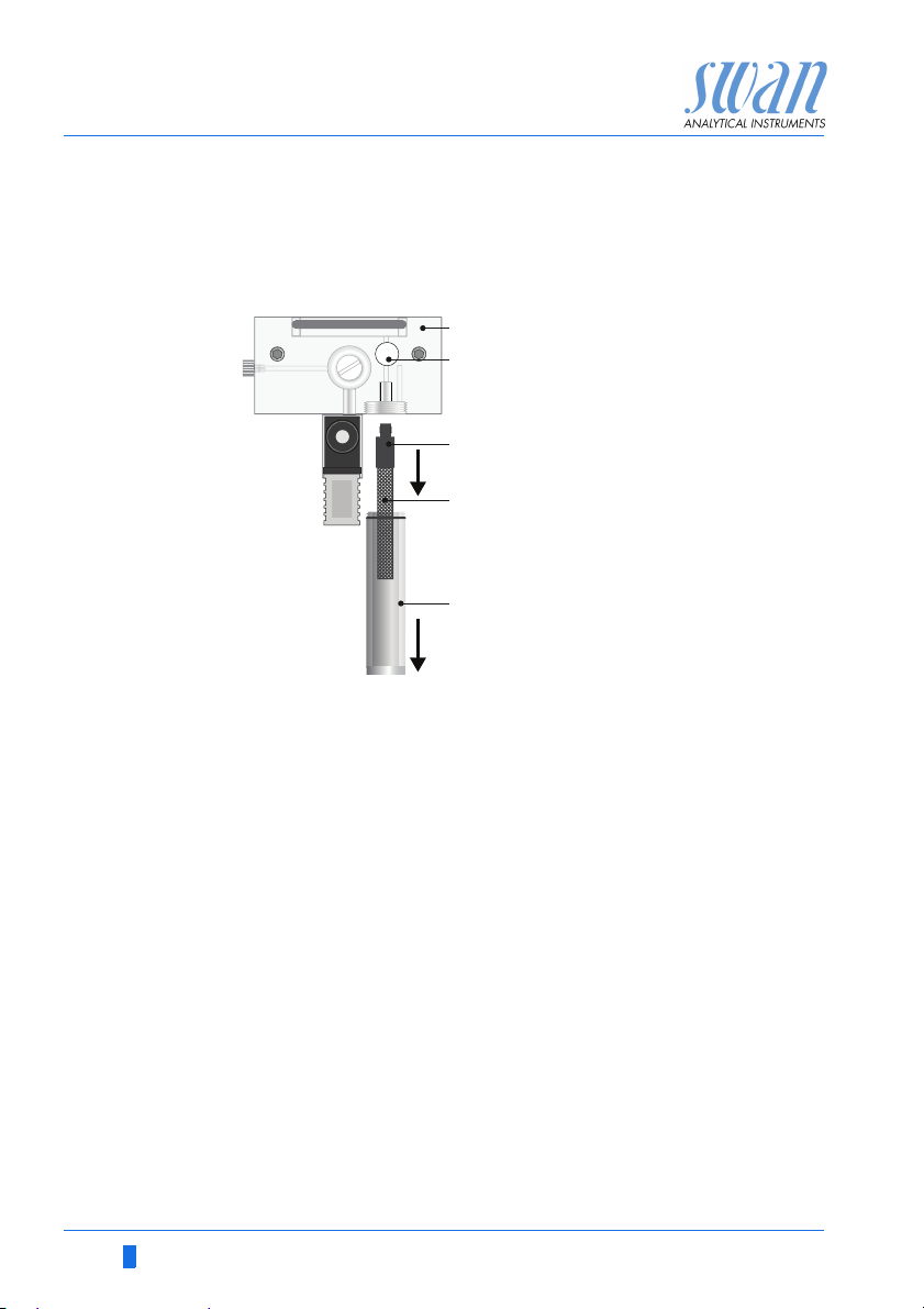
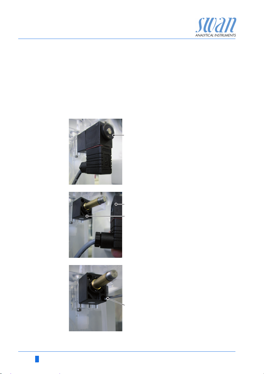
6.11. Cleaning the solenoid valve
Disassemble
the solenoid
valve
The solenoid valves are mounted at the bottom of the flow cell
block. The solenoid valve should be disassembled if it does not
switch anymore or if it is clogged.
1 Switch off the instrument according to instructions in Stop of
Operation for Maintenance, p. 45
2 Loosen the nut (A).
A
3 Remove the solenoid coil (B) from
the valve body (C).
B
C
4 Loosen the fixing screws of the
valve body with a 2.5 mm Allen key
(D).
62 A-96.250.631 / 280219

AMI Codes-II TC
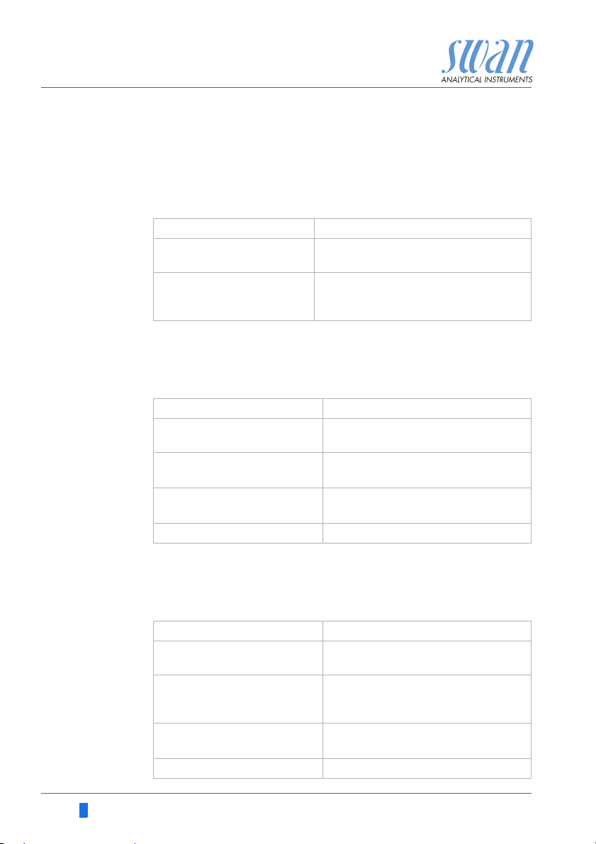
E
Maintenance
NOTICE: The O-rings inside the
valve body may stick on the flow
cell and fall down if the valve body
is removed.
5 Remove the valve body from the
flow cell.
6 Remove the base plate (G) with a
screw driver size 0 (F).
F
G
The membrane (H) is now
visible.
7 Clean base plate (G) and mem-
H
brane (H) with clean water.
Assemble Assemble the solenoid valve in reverse order.
A-96.250.631 / 280219 63

AMI Codes-II TC
Maintenance
6.12. Longer Stop of Operation
1 Put the suction lances into a bucket with clean water.
2 Start <Fill system>.
The reagent tubes are flushed with water.
3 Remove the suction lance from the water.
4 Start <Fill system> again.
The water will be pumped out of the reagent tubes.
5 Stop sample flow.
6 Wait until level in flow cell has fallen to the shorter tube inside
the cell.
7 Shut off power of the instrument.
8 Empty the flow cell completely.
9 Open the occlusion frames of the peristaltic pump, see Replace
the Pump Tubes, p. 59.
If option pH is installed
10 Unscrew and remove the connector from the pH sensor.
11 Put the connector cap onto the sensor connector.
12 Fill 3.5 molar KCl (if not available: water) into the rubber cap.
13 Remove the pH sensor from the flow cell and place the rubber
cap on the tip of the sensor.
CAUTION
Damage of pH sensor
Wrong storage will damage the pH sensor.
Never store the pH sensor dry.
Store the pH sensor with tip pointing downwards in a frost-
protected room.
64 A-96.250.631 / 280219

AMI Codes-II TC
Troubleshooting
7. Troubleshooting
This chapter provides some hints to make troubleshooting easier.
For any detailed information how to handle or clean parts please
see Maintenance, p. 44. For any detailed information how to program the instrument please see Program List and Explanations, p.
80.
7.1. General Instructions
NOTICE: The sample for the manual measurement (with DPD)
must be taken directly from the flow cell.
If you need further help please contact your dealer. Note serial
number of instrument and all diagnostic values before doing so.
Diagnostic
values
Frequently
asked
questions
Zero photometry: 10’000–16’000 Hz (mostly near 16 000 Hz)
Slope photometry: 0.8–1.2
pH offset: New pH sensor: near 0, old pH sensor > 50 mV
pH slope: typically: 55–62 mV/pH unit.
Problem Possible Reasons
Unstable values
Codes display
higher or lower than
manual measurement
Sample flow alarm,
but there is sample
Sample taken too close to feeding line
Sample flow too irregular or too low
Wrong manual measurement or old
chemicals have been used. Repeat the
verification.
Reagents of AMI Codes mixed wrongly or
not completely
Check sample flow at photometer outlet.
It must be at least 100 ml / min. For that
place the photometer outlet tube into a
measuring cup for 1 minute.
Check sample line for pressure fluctua-
tion.
Check for regular air bubble pattern.
Check flow alarm values in menu 5.3.1.3,
p. 92)
A-96.250.631 / 280219 65
AMI Codes-II TC
Troubleshooting
7.2. Calibration Errors
7.2.1 Process calibration tc2
Possible error
message
7.2.2 Process pH
Possible error
message
Slope error:
Possible cause Corrective Action
Wrong manual measurement.
Wrong reagent mixture
Reagents not complete-
ly solved in water.
Offset error:
Possible cause Corrective Action
Manual measurement
wrong.
Slope of last calibration
wrong.
pH sensor dirty, old or
defect.
Cable connector corroded. Replace cable and sensor.
Repeat the manual measurement.
Use fresh reagents.
Make a correct mixture.
Mix long and intensively.
Repeat the manual measurement.
Clean or replace pH sensor, see
Maintenance of pH sensor, p. 58.
7.2.3 Standard pH
Possible
error message
Offset error or Slope error:
Possible cause Corrective Action
Old, dirty or wrong buffer
solutions.
Verify programmed buffer
values with the values of
the buffer solution used.
pH sensor dirty, old or
defect.
Cable connector corroded. Replace cable and sensor.
Check buffers expiration date if
necessary order new buffer.
Change programmed buffer values or use correct buffer solution.
Clean or replace pH sensor, see
Maintenance of pH sensor, p. 58.
66 A-96.250.631 / 280219
AMI Codes-II TC
47 B/s
HOLD 14:10:45
R1
0.26 ppm
7.32 ppm
R2
26.6 °C
tc
1
tc
2
1
Installation
Operation
Diagnostics
Messages
Maintenance
Main Menu
1.1
Maintenance List
Pending Errors
Messages
Message List
1.1.5
Pending Errors
Error Code E002
Alarm low
<Enter> to Acknowledge
Troubleshooting
7.3. Error List
Error
Non-fatal Error. Indicates an alarm if a programmed value is exceeded.
Such Errors are marked E0xx (bold and black).
Fatal Error (blinking symbol)
Control of dosing devices is interrupted.
The indicated measured values are possibly incorrect.
Fatal Errors are divided in the following two categories:
Errors which disappear if correct measuring conditions are re-
covered (i.e. Sample Flow low).
Such Errors are marked E0xx (bold and orange)
Errors which indicate a hardware failure of the instrument.
Such Errors are marked E0xx (bold and red)
Error or fatal Error
Error not yet acknowledged.
Check Pending Errors 1.1.5 * and
take corrective action.
Press [ENTER].
A-96.250.631 / 280219 67
Reagent level low
Indicates the remaining reagent in percent
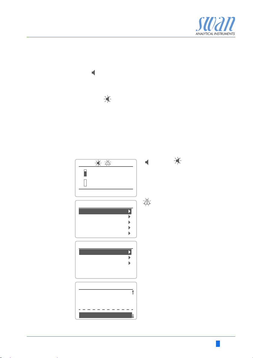
Navigate to menu Messages.
Press [ENTER].
Navigate to menu Pending Errors.
Press [ENTER].
Press [ENTER] to acknowledge the
Pending Errors. The Error is reset and
saved in the Message List.

AMI Codes-II TC
Troubleshooting
Error Description Corrective action
E001 Alarm high tc1
(Total chlorine 1)
E002 Alarm low tc1
(Total chlorine 1)
E003 Alarm high tc2
(Total chlorine 2)
E004 Alarm low tc2
(Total chlorine 2)
E005 Alarm high cdc
E006 Alarm low cdc
E007 Sample Temp.high
E008 Sample Temp. low
– check process
– check programmed value, see
5.3.1.1.1.1, p. 91
– check process
– check programmed value, see
5.3.1.1.1.25, p. 91
– check process
– check programmed value, see
5.3.1.1.2.1, p. 91
– check process
– check programmed value, see
5.3.1.1.2.25, p. 91
– check process
– check programmed value, see
5.3.1.1.3.1, p. 91
– check process
– check programmed value, see
5.3.1.1.3.25, p. 91
– check sample temperature
– check programmed value 5.3.1.2.1, p.
92
– check sample temperature
– check programmed value 5.3.1.2.25, p.
92
E009 Sample Flow high
– check Inlet pressure
– readjust sample flow
– check program value 5.3.1.3.2, p. 92
68 A-96.250.631 / 280219

AMI Codes-II TC
Troubleshooting
Error Description Corrective action
E010 Sample Flow low
E011 Temp. shorted
E012 Temp. disconnected
E013 Case Temp. high
E014 Case Temp. low
E015 Valve 1 defective
E016 DIS invalid
E017 Control Timeout
– check Inlet pressure
– readjust sample flow
– clean instrument, see Cleaning the
protective Filter, p. 54
– check program value 5.3.1.3.35, p. 92
– check wiring of temperature sensor, see
Connection Diagram, p. 28
– check temperature sensor
– check wiring of temperature sensor, see
Connection Diagram, p. 28
– check temperature sensor
– check case/environment temperature
– check program value
– check case/environment temperature
– check program value
– check Valve 1, see Cleaning the
solenoid valve, p. 62
– This error appears after start-up and will
disappear after the first valid
measurement is finished.
– check control device or programming in
Installation, Relay contact, Relay 1 and
2 5.3.2/3, p. 93
E018 Reagent Pump
E019 Photometer not con-
nected
A-96.250.631 / 280219 69
– shut off power
– check wiring, see Connection Diagram,
p. 28
– shut off power
– check wiring, see Connection Diagram,
p. 28

AMI Codes-II TC
Troubleshooting
Error Description Corrective action
E020 Photometer dirty
E021 Absorbance too high
E022 Reagent empty
E023 Cleaning Solution
E024 Input active
E026 IC LM75
E028 Signal output open
E030 EEprom Frontend
E031 Calibration Recout
E032 Wrong Frontend
E033 Alarm high pH
– check process
– clean the photometer, see Cleaning the
Photometer, p. 55
– Appears if disinf. value is too high
– Check dosing system or process
– refill reagents,
see Refill or replace Reagents, p. 46
– refill cleaning solution
– See If Fault Yes is programmed in Menu
5.3.4, p. 97
– call service
– check wiring on signal outputs 1 and 2
– call service
– call service
– call service
– check process
– check programmed value, see 5.3.1.4.1,
p. 92
E034 Alarm low pH
– check process
– check programmed value, see
5.3.1.4.25, p. 93
70 A-96.250.631 / 280219

AMI Codes-II TC
Troubleshooting
Error Description Corrective action
E049 Power-on
E050 Power-down
E065 DPD / Buffer
E067 Cleaning Solution
– none, normal status
– none, normal status
– Operating display, upper status line.
The number next to the triangle,
indicates the remaining reagents in %.
Refill reagents on time. See Refill or
replace Reagents, p. 46.
– Operating display, lower status line. The
number next to the triangle, indicates
the remaining cleaning solution in %.
Refill cleaning solution on time.
A-96.250.631 / 280219 71

AMI Codes-II TC
A
Troubleshooting
7.4. Opening the peristaltic pump housing
For some electrical connections (e.g. when replacing suction lances), it is necessary to open the housing of the peristaltic pump. To
do this, proceed as follows:
1 Switch off the analyzer according to Stop of Operation for Main-
tenance, p. 45.
2 Remove the protection cap and all pump tubes as described in
Dismount pump tubes, p. 60.
3 Unscrew the 4 screws of the peristaltic pump housing and re-
move the cover.
4 Disconnect the motor connector [A].
A Motor connector
5 Feed the cable into the housing through one of the PG7 cable
glands.
6 Connect the cable to the terminal block of the peristaltic pump
according to Connection Diagram, p. 28
7 Reassemble in reverse order.
.
72 A-96.250.631 / 280219

AMI Codes-II TC
A
B
CDEF G
Troubleshooting
7.5. Replacing Fuses
WARNING
External Voltage.
External supplied devices connected to relay 1 or 2 or to the
alarm relay can cause electrical shocks.
Make sure that the devices connected to the following con-
tacts are disconnected from the power before resuming installation.
– relay 1
– relay 2
– alarm relay
When a fuse has blown, find out the cause and fix it before
replacing it with a new one.
Use tweezers or needle-nosed pliers to remove the defective fuse.
Use original fuses provided by SWAN only.
A-96.250.631 / 280219 73
A
1.6 AT/250V Instrument power supply
B
1.0 AT/250V Relay 1
C
1.0 AT/250V Relay 2
D
1.0 AT/250V Alarm relay
E
1.0 AF/125V Signal output 2
F
1.0 AF/125V Signal output 1
G
1.0 AF/125V Signal output 3

AMI Codes-II TC
Program Overview
8. Program Overview
For explanations about each parameter of the menus see Program
List and Explanations, p. 80.
Menu 1 Messages informs about pending errors and mainte-
nance tasks and shows the error history. Password protection
possible. No settings can be modified.
Menu 2 Diagnostics is always accessible for everybody. No
password protection. No settings can be modified.
Menu 3 Maintenance is for service: Calibration, simulation of
outputs and set time/date. Please protect with password.
Menu 4 Operation is for the user, allowing to set limits, alarm
values, etc. The presetting is done in the menu Installation
(only for the System engineer). Please protect with password.
Menu 5 Installation: Defining assignment of all inputs and
outputs, measuring parameters, interface, passwords, etc.
Menu for the system engineer. Password strongly recommended.
8.1. Messages (Main Menu 1)
Pending Errors Pending Errors 1.1.5* * Menu numbers
1.1*
Maintenance List Maintenance List 1.2.5*
1.2*
Message List Number 1.3.1*
1.3* Date, Time
74 A-96.250.631 / 280219

AMI Codes-II TC
Program Overview
8.2. Diagnostics (Main Menu 2)
Identification Designation AMI Codes-II TC * Menu numbers
2.1* Version V6.20 - 05/18
Peripherals PeriClip 1 / 1.06 2.1.3.1*
2.1.3* PeriClip 2 only with cleaning module
Factory Test Instrument 2.1.4.1*
2.1.4* Motherboard
Front End
Operating Time Years / Days / Hours / Minutes / Seconds 2.1.5.1*
2.1.5*
Sensors Photometer Absorbance
2.2* 2.2.1* (Raw value) Hz
Cal. History Number 2.2.1.4.1*
2.2.1.4* Date, Time
Factor fc
Factor tc
Ver. History Number 2.2.1.5.1*
2.2.1.5* Date, Time
Absorbance
Reference value
pH Electrode Current Value / (Raw value)
2.2.2* Cal. History Number 2.2.2.5.1*
2.2.2.5* Date, Time
Offset / Slope
Miscellaneous Case Temp. 2.2.3.1*
2.2.3*
Sample Sample ID 2.3.1*
2.3* Sample Flow B/s
(Raw value) Hz
Temperature / (Nt5k) only with option pH
I/O State Alarm Relay 2.4.1*
2.4* Relay 1 & 2 2.4.2*
Input
Signal Output 1 & 2
Interface Protocol 2.5.1* (only with RS485
2.5* Baud rate interface)
A-96.250.631 / 280219 75

AMI Codes-II TC
Program Overview
8.3. Maintenance (Main Menu 3)
Calibration Total chlorine 2 Current Value * Menu numbers
3.1* 3.1.1* Factor
Process Value 3.1.1.4*
Process pH Current Value
3.1.2* Offset
Process Value 3.1.2.4*
Standard pH (Progress) 3.1.3.5*
3.1.3*
Service Verification (Progress) 3.2.1.1*
3.2* 3.2.1*
Fill System (Progress) 3.2.2.5*
3.2.2*
Simulation Alarm Relay 3.3.1*
3.3* Relay 1 3.3.2*
Relay 2 3.3.3*
Signal Output 1 3.3.4*
Signal Output 2 3.3.5*
Valve 3.3.6*
Set Time (Date), (Time)
3.4*
Cleaning Parameter Mode 3.5.1.1*
3.5* 3.5.1* Start time / Calendar 3.5.1.xx*
Delay 3.5.1.3*
Signal Outputs 3.5.1.4*
Output/Control 3.5.1.5*
Fill Channel 11 (Progress) 3.5.2.5*
3.5.2*
Fill Channel 12 (Progress) 3.5.3.5*
3.5.3*
76 A-96.250.631 / 280219

AMI Codes-II TC
Program Overview
8.4. Operation (Main Menu 4)
Sensors Filter Time Const. 4.1.1*
4.1* Hold after Cal. 4.1.2*
Meas. Interval 4.1.3*
Default pH 4.1.4*
Relay Contacts Alarm Relay Total chlorine 1 Alarm High 4.2.1.1.1*
4.2* 4.2.1* 4.2.1.1* Alarm Low 4.2.1.1.25*
Hysteresis 4.2.1.1.35*
Delay 4.2.1.1.45*
Total chlorine 2 Alarm High 4.2.1.2.1*
4.2.1.2* Alarm Low 4.2.1.2.25*
Hysteresis 4.2.1.2.35*
Delay 4.2.1.2.45*
Calc. Dichl. Alarm High 4.2.1.3.1*
4.2.1.3* Alarm Low 4.2.1.3.25*
Hysteresis 4.2.1.3.35*
Delay 4.2.1.3.45*
Alarm pH Alarm High 4.2.1.4.1*
4.2.1.4* Alarm Low 4.2.1.4.25*
Hysteresis 4.2.1.4.35*
Delay 4.2.1.4.45*
Relay 1 & 2
4.2.2* & 4.2.3* Setpoint 4.2.x.100*
Hysteresis 4.2.x.200*
Delay 4.2.x.30*
Input Active 4.2.4.1*
4.2.4* Signal Outputs 4.2.4.2*
Output / Control 4.2.4.3*
Fault 4.2.4.4*
Delay 4.2.4.5*
Logger Log Interval 4.3.1*
4.3* Clear Logger 4.3.2*
Eject USB Stick 4.3.3* (If USB interface is installed)
Display Screen 1 Row 1 4.4.1.1*
4.4* 4.4.1* Row 2 4.4.1.2*
Row 3 4.4.1.3*
Screen 2 Row 1 4.4.2.1*
4.4.2* Row 2 4.4.2.2*
Row 3 4.4.2.3* * Menu numbers
A-96.250.631 / 280219 77

AMI Codes-II TC
Program Overview
8.5. Installation (Main Menu 5)
Sensors Dimension 5.1.1* * Menu numbers
5.1* Ref. Verification 5.1.2*
Meas. Range 5.1.3*
Standards Standard 1 5.1.4.1* only with pH option
5.1.4* Standard 2 5.1.4.2*
Cleaning 5.1.5 only with Cleaning Module
Signal Outputs Signal Output 1 & 2 Parameter 5.2.1.1 & 5.2.2.1*
5.2* 5.2.1* & 5.2.2* Current Loop 5.2.1.2 & 5.2.2.2*
Function 5.2.1.3 & 5.2.2.3*
Scaling Range Low 5.2.x.40.10*
5.2.x.40 Range High 5.2.x.40.20*
Relay Contacts Alarm Relay Disinfection Total chlorine 1 Alarm High 5.3.1.1.1.1*
5.3* 5.3.1* 5.3.1.1* 5.3.1.1.1* Alarm Low 5.3.1.1.1.25*
Hysteresis 5.3.1.1.1.35*
Delay 5.3.1.1.1.45*
Total chlorine 2 Alarm High 5.3.1.1.2.1*
5.3.1.1.2* Alarm Low 5.3.1.1.2.25*
Hysteresis 5.3.1.1.2.35*
Delay 5.3.1.1.2.45*
Calc. Dichl. Alarm High 5.3.1.1.3.1*
5.3.1.1.3* Alarm Low 5.3.1.1.3.25*
Hysteresis 5.3.1.1.3.35*
Delay 5.3.1.1.3.45*
Sample Flow Flow Alarm 5.3.1.3.1*
5.3.1.3* Alarm High 5.3.1.3.2*
Alarm Low 5.3.1.3.35*
Case Temp. high 5.3.1.5*
Case Temp. low 5.3.1.6*
Temperature Alarm High 5.3.1.5.1*
5.3.1.5* Alarm Low 5.3.1.5.25*
pH Alarm High 5.3.1.6.1*
5.3.1.6* Alarm Low 5.3.1.6.25*
Hysteresis 5.3.1.6.35*
Delay 5.3.1.6.45*
78 A-96.250.631 / 280219

AMI Codes-II TC
Program Overview
Relay 1 & 2 Function 5.3.2.1 & 5.3.3.1*
5.3.2* & 5.3.3* Parameter 5.3.2.x & 5.3.3.x*
Setpoint 5.3.2.x & 5.3.3.x*
Hysteresis 5.3.2.x & 5.3.3.x*
Delay 5.3.2.x & 5.3.3.x*
Input Active 5.3.4.1*
5.3.4* Signal Outputs 5.3.4.2*
Output/Control 5.3.4.3*
Fault 5.3.4.4*
Delay 5.3.4.5*
Miscellaneous Language 5.4.1* *Menu numbers
5.4* Set defaults 5.4.2*
Load Firmware 5.4.3*
Password Messages 5.4.4.1*
5.4.4* Maintenance 5.4.4.2*
Operation 5.4.4.3*
Installation 5.4.4.4*
Sample ID 5.4.5*
Line Break Detection 5.4.6*
Interface Protocol 5.5.1* (only with RS485
5.5* Device Address 5.5.21* interface)
Baud Rate 5.5.31*
Parity 5.5.41*
A-96.250.631 / 280219 79

AMI Codes-II TC
Program List and Explanations
9. Program List and Explanations
1 Messages
1.1 Pending Errors
1.1.5 Provides the list of active errors with their status (active,
1.2 Maintenance List
1.2.5 Demands necessary maintenance, e.g. preparing new reagents.
1.2 Message List
1.3.1 Shows the error history: Error code, date / time of issue and status
2 Diagnostics
2.1 Identification
2.1.3 Peripherals: PeriClip 1: Firmware of peristaltic pump (e.g. 1.06)
2.1.4 Factory Test: Test date of the Instrument, Motherboard and
2.1.5 Operating Time: Years/Days/Hours/Minutes/Seconds
2.2 Sensors
2.2.1 Photometer:
2.2.1.4 Cal. History: Shows the diagnostic values of the last calibrations.
acknowledged). If an active error is acknowledged, the alarm relay
is active again. Cleared errors are moved to the Message list.
(active, acknowledged, cleared). 65 errors are memorized. Then
the oldest error is cleared to save the newest error (circular buffer).
In diagnostics mode, the values can only be viewed, not modified.
Designation: View the Designation of instrument.
Ver sio n: Firmware of instrument (e.g. V6.20-05/18)
Frontend. QC factory test.
Absorbance: Process value, depends on sample.
Raw value: Shows the actual photometer signal in Hz.
Number: Counter for the calibrations
Date, Time: Date and time assigned to a number.
Slope: Slope photometer: 0.8–1.2
80 A-96.250.631 / 280219

AMI Codes-II TC
Program List and Explanations
2.2.1.5 Ver. History: Shows the verification values of the last verifications:
Number: Calibration counter.
Date, Time: Date and time of the calibration.
Absorbance: Measured absorbance of the reference kit.
Reference value: True value of the reference kit according to label.
2.2.2 pH Electrode: Only if option pH is installed.
Current Value: Shows the actual measured pH value.
Raw value: Shows the actual electrode voltage in mV.
2.2.2.5 Cal. History: Shows the calibration values of the last pH sensor
calibrations. Offset in mV and slope in mV/pH.
Typical offset of pH electrode: < 30 mV.
Max. tolerated offset: < 60 mV
Typical slope of pH electrode: 55 – 65 mV/pH unit.
Max. limits: 40–65 mV/pH
2.2.3 Miscellaneous:
2.2.3.1 Case Temp: Shows the current temperature in °C inside the
2.3 Sample
2.3.1 Sample ID: Shows the identification assigned to a sample. This
2.4 I/O State
2.4.1/2.4.2
transmitter.
identification is defined by the user to identify the location of the
sample.
Sample Flow: Shows the actual sample flow in B/s (bubbles per
second). Sample flow must be above 5 B/s.
Raw value: Shows the raw value of the sample flow in Hz.
Temperature: Only if option pH is installed.
Actual sample temperature in °C and in Ohm (NT5K)
Shows current status of all in- and outputs.
Alarm Relay: Active or inactive
Relay 1 & 2: Active or inactive
Input: Open or closed
Signal Output 1 & 2: Actual current in mA
Signal Output 3: Actual current in mA (if option is installed)
A-96.250.631 / 280219 81

AMI Codes-II TC
Program List and Explanations
2.5 Interface
Only available if optional interface is installed.
Shows the programmed communication settings.
3 Maintenance
3.1 Calibration
In this menu, you can correct measuring values (disinfectant and
pH) or calibrate offset and slope of pH electrode.
3.1.1 Total chlorine 2: Possibility to correct the disinfectant value. See
Process Calibration of tc 2, p. 51, for more details.
3.1.2 Process pH: Only available, if option pH has been installed.
3.1.3 Standard pH: Only available, if option pH has been installed.
3.2 Service
3.2.1 Verification: Performs a verification using the reference kit. Follow
3.2.2 Fill System: Activates the reagent pump. The function Fill System
3.3 Simulation
Correction of pH electrode. See Process Calibration of tc 2, p. 51,
for details.
Calibration of pH electrode with the two standard solutions
programmed in Installation 5.1.3. See Standard pH, p. 53, for
details.
dialog. See Verification, p. 50.
is used to fill or flush the reagent tubes.
To simulate a value or a relay state, select the
alarm relay,
relay 1 or 2
signal output 1 or 2
valve 1
with the [ ] or [ ] key.
Press the [Enter] key.
Change the value or state of the selected item with the [ ] or
[] key.
82 A-96.250.631 / 280219

AMI Codes-II TC
Program List and Explanations
Press the [Enter] key.
The value is simulated by the relay / signal output.
Alarm Relay: Active or inactive
Relay 1 & 2: Active or inactive
Signal Output 1 & 2: Actual current in mA
Signal Output 3: Actual current in mA (if option is installed)
Valve 1 Active or inactive
At the absence of any key activities, the instrument will switch back
to normal mode after 20 min. If you quit the menu, all simulated values will be reset.
3.4 Set Time
Adjust date and time.
3.5 Cleaning
Automatic cleaning process using the Cleaning module-II
controlled by transmitter of AMI Codes-II TC.
– Measurement is interrupted.
– Flow error interrupts cleaning.
– Cleaning does not start: E022 Reagent empty, E023
Cleaning solution, no flow.
3.5.1 Parameter:
3.5.1.1 Mode: Select daily, weekly or off.
3.5.1.xx Start time/ Calendar: Time of day respectively weekday(s) for the
3.5.1.3 Delay: During cleaning plus the delay time, the status of the signal-
3.5.1.4 Signal Outputs: Select the operation mode of the signal outputs
automatic start of the cleaning process.
and control outputs is as set below.
Range: 0–6’000 sec
during cleaning:
Cont.: Signal outputs continue to issue the measured value.
Hold: Signal outputs hold the last valid measured value.
Off: Signal outputs are switched off (set to 0 or 4 mA).
Measurement is interrupted. Errors, except fatal errors,
are not issued.
Errors, except fatal errors, are not issued.
A-96.250.631 / 280219 83

AMI Codes-II TC
Program List and Explanations
3.5.1.5 Output/Control: Relay or signal output:
Cont.: Controller continues normally.
Hold: Controller continues based on the last valid value.
Off: Controller is switched off.
3.5.2 Fill Channel 11: Activates the cleaning pump and switches the
3.5.3 Fill Channel 12: Activates the cleaning pump and switches the
valve to the cleaning solution 1 (right canister)
valve to the cleaning solution 2 (left canister)
4 Operation
4.1 Sensors
4.1.1 Filter Time Constant: Used to damp noisy signals. The higher the
filter time constant, the slower the system reacts to changes of the
measured value.
Range: 5–300 sec
4.1.2 Hold after Cal: Delay permitting the instrument to stabilize again
after calibration. During calibration- plus hold-time, the signal
outputs are frozen (held on last valid value), alarm values, limits are
not active.
Range: 0–6‘000 sec
4.1.3 Meas. Interval: The measuring interval of “Total chlorine 2” can be
4.1.4 Default pH: If the pH value of the sample is known it can be entered
4.2 Relay Contacts
4.3 Logger
set according to the process requirements.
Range: 3–60 min
in this menu. This menu only appears if the pH option is not
installed.
Range: 0–14 pH
See 5.3 Relay Contacts, p. 90
The instrument is equipped with an internal logger. The data can be
copied to a PC with an USB stick if option USB interface is
installed.
The logger can save approx. 1500 data records. Records consists
of: Date, time, alarms, measured value, measured value
uncompensated, temperature, flow.
Range: 1 Second to 1 hour
84 A-96.250.631 / 280219

AMI Codes-II TC
Program List and Explanations
4.3.1 Log Interval: Select a convenient log interval. Consult the table
below to estimate the max logging time. When the login buffer is
full, the oldest data record is erased to make room for the newest
one. (circular buffer)
Interval 1 s 5 s 1 min 5 min 10 min 30 min 1 h Event
Driven
Time 25 min 2 h 25 h 5 d 10 d 31 d 62 d
4.3.2 Clear Logger: If confirmed with yes, the complete logger data is
deleted. A new data series is started.
4.4 Display
Process values are displayed on two screens. Toggle screens with
the [ ] key. Each screen displays max. 3 process values.
4.4.1 Screen 1
4.4.1.1 Row 1
4.4.1.2 Row 2
4.4.1.3 Row 3
Possible settings for all rows are:
None
Total chlorine 1
Total chlorine 2
Calc. dichloramine
pH
4.4.2 Screen 2
Same as screen 1.
5 Installation
5.1 Sensors
5.1.1 Dimension: The measuring value can be displayed as ppm or mg/ l
5.1.2 Ref. Verification: Set absorbance value of verification kit according
A-96.250.631 / 280219 85
to label.
Range: 0.200–0.600

AMI Codes-II TC
Program List and Explanations
5.1.3 Meas. Range: available settings are standard or extended.
select “standard” for application up to 5 ppm
select “extended” for applications up to 10 ppm
NOTICE: The reagent consumption of the instrument is higher if
the measuring mode extended is set.
5.1.5 Cleaning: Program if one or two solutions are used on Cleaning
module. See 3.5 Cleaning, p. 83
Range: 1 Solution, 2 Solutions
5.2 Signal Outputs
5.2.1&5.2.2 Signal Output 1 and 2: Assign process value, the current loop
5.2.1.1 Parameter: Assign one of the process values to the signal output.
5.2.1.2 Current Loop: Select the current range of the signal output.
5.2.1.3 Function: Define if the signal output is used to transmit a process
range and a function to each signal output.
NOTICE: The navigation in the menu <Signal Output 1> and
<Signal Output 2> is equal. For reason of simplicity only the
menu numbers of Signal Output 1 are used in the following.
Available values:
Total chlorine 1
Total chlorine 2
Calc. dichloramine (Calculated dichloramine)
Temperature
Sample flow
pH
Make sure the connected device works with the same current
range.
Available ranges: 0– 20 mA or 4–20 mA
value or to drive a control unit. Available functions are:
Linear, bilinear or logarithmic for process values.
See As process values, p. 87
Control upwards or control downwards for controllers.
See As control output, p. 88
86 A-96.250.631 / 280219
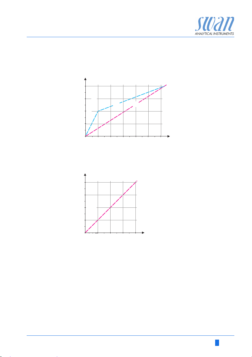
AMI Codes-II TC
20
0.0 0.1 0.2 0.3 0.4 0.5
10 12
(0 - 20 [mA])
0 / 4
(4 - 20 [mA])
[mA]
X
AB
20
1
01234
10 100 1’000 10’000
10 12
(0 - 20 [mA])
0 / 4
426
(4 - 20 [mA])
[mA]
X
Program List and Explanations
As process
values
The process value can be represented in 3 ways: linear, bilinear or
logarithmic. See graphs below.
ABlinear
X Measured value
bilinear
5.2.1.40 Scaling: Enter beginning and end point (Range low & high) of the
5.2.1.40.10 Range low: 0–20 ppm or 0–20 mg/l
5.2.1.40.20 Range high: 0–20 ppm or 0–20 mg/ l
5.2.1.40.11 Range low: 0–20 ppm or 0–20 mg/l
5.2.1.40.21 Range high: 0–20 ppm or 0–20 mg/ l
A-96.250.631 / 280219 87
X Measured value (logarithmic)
linear or logarithmic scale. In addition, the midpoint for the bilinear
scale.
Parameter Total chlorine 1
Parameter Total chlorine 2

AMI Codes-II TC
Program List and Explanations
Parameter Calc. dichloramine
5.2.1.40.12 Range low: 0– 20 ppm or 0–20 mg/l
5.2.1.40.22 Range high: 0–20 ppm or 0–20 mg/ l
Parameter Temperature
5.2.1.40.13 Range low: -30 to +120 °C
5.2.1.40.23 Range high: -30 to +120 °C
Parameter Sample flow
5.2.1.40.14 Range low: 0 –600 B / s
5.2.1.40.24 Range high: 0 –600 B/s
Parameter pH
5.2.1.40.15 Range low: 0 –14 pH
5.2.1.40.25 Range high: 0 –14 pH
As control out-
Signal outputs can be used for driving control units. We distinguish
different kinds of controls:
put
P-controller: The controller action is proportional to the devia-
tion from the setpoint. The controller is characterized by the
P-Band. In the steady-state, the setpoint will never be
reached. The deviation is called steady-state error.
Parameters: setpoint, P-Band
PI-controller: The combination of a P-controller with an
I-controller will minimize the steady-state error. If the reset
time is set to zero, the I-controller is switched off.
Parameters: setpoint, P-Band, reset time.
PD-controller: The combination of a P-controller with a
D-controller will minimize the response time to a fast change
of the process value. If the derivative time is set to zero, the
D-controller is switched off.
Parameters: setpoint, P-Band, derivative time.
PID-controller: The combination of a P-, an I - and a D-con-
troller allows a proper control of the process.
Parameters: setpoint, P-Band, reset time, derivative time.
Ziegler-Nichols method for the optimization of a PID controller:
Parameters: Setpoint, P-Band, Reset time, Derivative time
88 A-96.250.631 / 280219
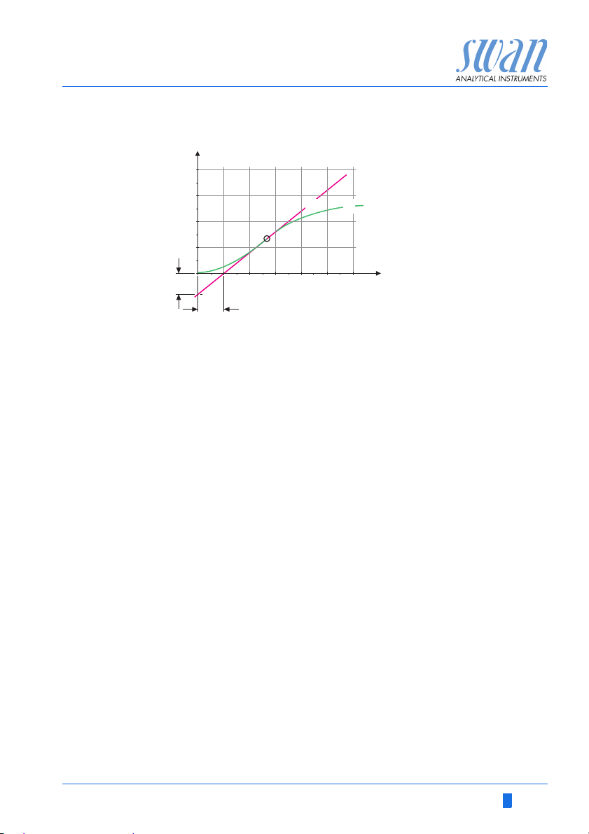
AMI Codes-II TC
X
Y
B
A
L
a
Program List and Explanations
A
Response to maximum control output
B
Tangent on the inflection point
X
Time
The point of intersection of the tangent with the respective axis will
result in the parameters a and L.
Consult the manual of the control unit for connecting and
programming details. Choose control upwards or downwards.
Control upwards/downwards
Setpoint: User-defined process value (Measured value or flow)
P-Band: Range below (upwards control) or above (downwards
control) the set-point, within the dosing intensity is reduced from
100% to 0% to reach the set-point without overshooting.
5.2.1.43 Control Parameters: if Parameters = Total chlorine 1
5.2.1.43.10 Setpoint: 0–20 ppm or 0–20 mg/l
5.2.1.43.20 P-Band: 0–20 ppm 0–20 mg/l
5.2.1.43 Control Parameters: if Parameters = Total chlorine 2
5.2.1.43.11 Setpoint: 0–20 ppm or 0–20 mg/l
5.2.1.43.21 P-Band: 0–20 ppm 0–20 mg/l
5.2.1.43 Control Parameters: if Parameters = Calc. dichloramine
5.2.1.43.12 Setpoint: 0–20 ppm or 0–20 mg/l
5.2.1.43.22 P-Band: 0–20 ppm 0–20 mg/l
5.2.1.43 Control Parameters: if Parameters = Temperature
5.2.1.43.13 Setpoint: -30 to +120 °C
5.2.1.43.23 P-Band: 0–100 °C
Xp
Tn
Tv
= 1.2/a
= 2L
= L/2
A-96.250.631 / 280219 89

AMI Codes-II TC
Program List and Explanations
5.2.1.43 Control Parameters: if Parameters = Sample Flow
5.2.1.43.14 Setpoint: 0– 600 B / s
5.2.1.43.24 P-Band: 0– 200 B / s
5.2.1.43 Control Parameters: if Parameters = pH
5.2.1.43.15 Setpoint: 0 –14 pH
5.2.1.43.25 P-Band: 0 –14 pH
5.2.1.43.3 Reset time: The reset time is the time till the step response of a
single I-controller will reach the same value as it will be suddenly
reached by a P-controller.
Range: 0–9’000 sec
5.2.1.43.4 Derivative time: The derivative time is the time till the ramp
response of a single P-controller will reach the same value as it will
be suddenly reached by a D-controller.
Range: 0–9’000 sec
5.2.1.43.5 Control timeout: If a controller action (dosing intensity) is constantly
5.3 Relay Contacts
5.3.1 Alarm Relay: The alarm relay is used as cumulative error indicator.
over 90% during a defined period of time and the process value
does not come closer to the setpoint, the dosing process will be
stopped for safety reasons.
Range: 0–720 min
Under normal operating conditions the contact is active.
The contact is inactive at:
Power loss
Detection of system faults like defective sensors or electronic
parts
High case temperature
Lack of reagents
Process values out of programmed ranges.
Program alarm levels, hysteresis values and delay times for the
following parameters:
Total chlorine 1
Total chlorine 2
Calc. dichloramine (Calculated dichloramine)
Temperature
Sample flow
pH
90 A-96.250.631 / 280219

AMI Codes-II TC
Program List and Explanations
5.3.1.1 Disinfection
5.3.1.1.1 Total chlorine 1
5.3.1.1.1.1 Alarm High: If the measured value rises above the alarm high
value, the alarm relay is activated and E001 is displayed in the
message list. Range: 0.00–20.00 ppm
5.3.1.1.1.25 Alarm Low: If the measured value falls below the alarm low value,
the alarm relay is activated and E002 is displayed in the message
list.
Range: 0.00–20.00 ppm
5.3.1.1.1.35 Hysteresis: Within the hyst. range, the relay does not switch. This
prevents damage of relays contacts when the measured value
fluctuates around the alarm value.
Range. 0.00–20.00 ppm
5.3.1.1.1.45 Delay: Duration, the activation of the alarm relay is retarded after
5.3.1.1.2 Total chlorine 2
5.3.1.1.2.1 Alarm High: If the measured value rises above the alarm high
5.3.1.1.2.25 Alarm Low: If the measured value falls below the alarm low value,
5.3.1.1.2.35 Hysteresis: Within the hyst. range, the relay does not switch. This
5.3.1.1.2.45 Delay: Duration, the activation of the alarm relay is retarded after
5.3.1.1.3 Calc. dichl.
5.3.1.1.3.1 Alarm High: If the measured value rises above the alarm high
5.3.1.1.3.25 Alarm Low: If the measured value falls below the alarm low value,
the measuring value has risen above/fallen below the programmed
alarm.
Range: 0.00–28‘800 sec
value, the alarm relay is activated and E003 is displayed in the
message list. Range: 0.00–20.00 ppm
the alarm relay is activated and E004 is displayed in the message
list.
Range: 0.00–20.00 ppm
prevents damage of relays contacts when the measured value
fluctuates around the alarm value.
Range. 0.00–20.00 ppm
the measuring value has risen above/fallen below the programmed
alarm.
Range: 0.00–28‘800 sec
value, the alarm relay is activated and E005 is displayed in the
message list. Range: 0.00–20.00 ppm
the alarm relay is activated and E006 is displayed in the message
list. Range: 0.00–20.00 ppm
A-96.250.631 / 280219 91

AMI Codes-II TC
Program List and Explanations
5.3.1.1.3.35 Hysteresis: Within the hyst. range, the relay does not switch. This
prevents damage of relays contacts when the measured value
fluctuates around the alarm value.
Range. 0.00–20.00 ppm
5.3.1.1.2.45 Delay: Duration, the activation of the alarm relay is retarded after
5.3.1.2 Sample Temp.: Only available if pH option is installed. Define the
5.3.1.2.1 Alarm High: If the sample temperature rises above the
5.3.1.2.25 Alarm Low: If the sample temperature falls below the programmed
5.3.1.3 Sample Flow: Define at which sample flow a flow alarm should be
5.3.1.3.1 Flow Alarm: Program whether the alarm relay should be activated if
5.3.1.3.2 Alarm High: If the measuring values rises above the programmed
5.3.1.3.35 Alarm Low: If the measuring values falls below the programmed
5.3.1.4 Alarm pH: Only available if pH option is installed. Define the
5.3.1.4.1 Alarm High: If the measured value rises above the alarm high
the measuring value has risen above/fallen below the programmed
alarm.
Range: 0.00–28‘800 sec
measuring value, which should issue an alarm high respectively
low.
programmed value E007 is issued. and low (E008)
Range: 30–70 °C
value E008 is issued.
Range: 0–20 °C
issued.
there is a flow alarm. The flow alarm will always be indicated in the
display, pending error list, saved in the message list and the logger.
Available values: Yes or No
NOTICE: Sufficient flow is essential for a correct measurement.
We recommend to program yes.
value E009 will be issued.
Range: 100–600 B/s
value E010 will be issued.
Range: 5–80 B/s
measuring value, which should issue an alarm high respectively
low.
value, the alarm relay is activated and E033 is displayed in the
message list.
Range: 0–14 pH
92 A-96.250.631 / 280219

AMI Codes-II TC
Program List and Explanations
5.3.1.4.25 Alarm Low: If the measured value falls below the alarm low value,
the alarm relay is activated and E034 is displayed in the message
list
Range: 0–14 pH
5.3.1.4.35 Hysteresis: Within the hyst. range, the relay does not switch. This
5.3.1.4.45 Delay: Duration, the activation of the alarm relay is retarded after
5.3.1.5 Case Temp. high: Set the alarm high value for temperature of elec-
5.3.1.6 Case Temp. low: Set the alarm low value for temperature of elec-
5.3.2/3 Relay 1 and 2: The contacts can be set as normally open or
5.3.2.1 Function = Limit upper/lower:
5.3.2.20 Parameter: select a process value
prevents damage of relays contacts when the measured value
fluctuates around the alarm value
Range: 0–14 pH
the measuring value has risen above/fallen below the programmed
alarm.
Range: 0–28‘800 sec
tronics housing. If the value rises above the programmed value
E013 is issued.
Range: 30–75 °C
tronics housing. If the value falls below the programmed value
E014 is issued.
Range: -10 to +20 °C
normally closed with a jumper. See Relay 1 and 2, p. 31.
The function of relay contacts 1 or 2 are defined by the user.
NOTICE: The navigation in the menu <Relay 1> and <Relay 2>
is equal. For reason of simplicity only the menu numbers of
Relay 1 are used in the following.
1 First select the functions as:
- Limit upper/lower,
- Control upwards/downwards,
- Timer
- Fieldbus
- End of Batch (relay 2 only)
2 Then enter the necessary data depending on the selected func-
tion.
When the relays are used as upper or lower limit switches, program
the following:
A-96.250.631 / 280219 93

AMI Codes-II TC
Program List and Explanations
5.3.2.300 Setpoint: If the measured value rises above respectively falls below
the set-point, the relay is activated.
Parameter Range
Total chlorine 1 0– 20 ppm
Total chlorine 2 0– 20 ppm
Calc. dichloramine 0 – 20 ppm
Temperature -30 to +120 °C
Sample flow 0–600 B/s
pH 0–14 pH
5.3.2.400 Hysteresis: within the hysteresis range, the relay does not switch.
5.3.2.50 Delay: Duration, the activation of the alarm relay is retarded after
5.3.2.1 Function = Control upwards/ downwards:
5.3.2.22 Parameter: Choose on of the following process values.
This prevents damage of relay contacts when the measured value
fluctuates around the alarm value.
Parameter Range
Total chlorine 1 0– 20 ppm
Total chlorine 2 0– 20 ppm
Calc. dichloramine 0 – 20 ppm
Temperature 0 to +100 °C
Sample flow 0–200 B/s
pH 0–14 pH
the measuring value has risen above/fallen below the programmed
alarm.
Range. 0–600 sec
The relays may be used to drive control units such as solenoid
valves, membrane dosing pumps or motor valves. When driving a
motor valve both relays are needed, relay 1 to open and relay 2 to
close the valve.
Total chlorine 1
Total chlorine 2
Calc. dichloramine
pH
Temperature
Sample Flow
94 A-96.250.631 / 280219

AMI Codes-II TC
Program List and Explanations
5.3.2.32 Settings: Choose the respective actuator:
Time proportional
Frequency
Motor valve
5.3.2.32.1
5.3.2.32.20 Cycle time: duration of one control cycle (on/off change).
5.3.2.32.30 Response time: Minimal time the metering device needs to react.
5.3.2.32.4 Control Parameters
5.3.2.32.1
5.3.2.32.21 Pulse frequency: Max. pulses per minute the device is able to re-
5.3.2.32.31 Control Parameters
5.3.2.32.1
5.3.2.32.22 Run time: Time needed to open a completely closed valve
5.3.2.32.32 Neutral zone: Minimal response time in % of the runtime. If the re-
5.3.2.32.4 Control Parameters
Actuator = Time proportional
Examples of metering devices that are driven time proportional are
solenoid valves, peristaltic pumps.
Dosing is controlled by the operating time.
Range: 0–600 sec.
Range: 0–240 sec.
Range for each Parameter same as 5.2.1.43, p. 89
Actuator = Frequency
Examples of metering devices that are pulse frequency driven are
the classic membrane pumps with a potential free triggering input.
Dosing is controlled by the repetition speed of dosing shots.
spond to. Range: 20–300/min.
Range for each Parameter same as 5.2.1.43, p. 89
Actuator = Motor valve
Dosing is controlled by the position of a motor driven mixing valve.
Range: 5–300 sec.
quested dosing output is smaller than the response time, no
change will take place.
Range: 1–20 %
Range for each Parameter same as 5.2.1.43, p. 89
5.3.2.1 Function = Timer:
The relay will be active repetitively depending on the programmed
time scheme.
A-96.250.631 / 280219 95

AMI Codes-II TC
Program List and Explanations
5.3.2.24 Mode: Operating mode (interval, daily, weekly)
5.3.2.24
5.3.2.340 Interval: The interval can be programmed within a range
5.3.2.44 Run Time: Enter the time the relay stays active.
5.3.2.54 Delay: during run time plus the delay time the signal and control
5.3.2.6 Signal Outputs: Select operating mode of the signal output:
5.3.2.7 Output/ Control: Select operating mode of the controller output:
5.3.2.24
Interval
of 1–1’440 min.
Range: 5–32’400 sec.
outputs are held in the operating mode programmed below.
Range: 0–6’000 sec.
Cont.: Signal outputs continue to issue the measured value.
Hold: Signal outputs hold the last valid measured value.
Measurement is interrupted. Errors, except fatal errors,
are not issued.
Off: Signal outputs are switched off (set to 0 or 4 mA).
Errors, except fatal errors, are not issued.
Cont.: Controller continues normally.
Hold: Controller continues based on the last valid value.
Off: Controller is switched off.
daily
The relay contact can be activated daily, at any time of a day.
5.3.2.341 Start time: to set the start time proceed as follows:
1 Press [Enter], to set the hours.
2 Set the hour with the [ ] or [ ] keys.
3 Press [Enter], to set the minutes.
4 Set the minutes with the [ ] or [ ] keys.
5 Press [Enter], to set the seconds.
6 Set the seconds with the [ ] or [ ] keys.
Range: 00:00:00–23:59:59
5.3.2.44 Run Time: see Interval
5.3.2.54 Delay: see Interval
5.3.2.6 Signal Outputs: see Interval
96 A-96.250.631 / 280219

AMI Codes-II TC
Program List and Explanations
5.3.2.7 Output/Control: see Interval
5.3.2.24
5.3.2.342 Calendar:
5.3.2.342.1 Start time: The programmed start time is valid for each of the pro-
5.3.2.342.2 Monday: Possible settings, on or off
5.3.2.342.8 Sunday: Possible settings, on or off
5.3.2.44 Run Time: see Interval
5.3.2.54 Delay: see Interval
5.3.2.6 Signal Outputs: see Interval
5.3.2.7 Output/Control: see Interval
weekly
The relay contact can be activated at one or several days, of a
week. The daily starting time is valid for all days.
grammed days. To set the start time see 5.3.2.341, p. 96.
Range: 00:00:00–23:59:59
to
5.3.2.1
5.3.2.1 Function = End of Batch:
5.3.4 Input: The functions of the relays and signal outputs can be de-
5.3.4.1 Active: Define when the input should be active:
A-96.250.631 / 280219 97
Function = Fieldbus:
The relay will be switched via the Profibus input. No further parameters are needed.
This function is only available on relay 2. It is used to communicate
with canal switching instruments from third-party suppliers. The relay closes for 1 sec. after each valid measurement. If End of Batch
is selected, no further selection is possible.
fined depending on the position of the input contact, i.e. no function,
closed or open.
The measurement is interrupted during the time the input is active.
No: Input is never active.
When closed Input is active if the input relay is closed
When open: Input is active if the input relay is open

AMI Codes-II TC
Program List and Explanations
5.3.4.2 Signal Outputs: Select the operation mode of the signal outputs
when the relay is active:
Cont.: Signal outputs continue to issue the measured
Hold: Signal outputs issue the last valid measured value.
Off: Set to 0 or 4 mA respectively. Errors, except fatal
5.3.4.3 Output/Control: (relay or signal output):
Cont.: Controller continues normally.
Hold: Controller continues on the last valid value.
Off: Controller is switched off.
5.3.4.4 Fault:
No: No message is issued in pending error list and the
Yes : Message E024 is issued and stored in the mes-
5.3.4.5 Delay: Time which the instrument waits, after the input is deactivat-
ed, before returning to normal operation.
Range: 0–6‘000 sec
5.4 Miscellaneous
5.4.1 Language: Set the desired language.
Available settings: German /English/ French/ Spanish
5.4.2 Set defaults: Reset the instrument to factory default values in three
different ways:
Calibration: Sets calibration values back to default. All other
values are kept in memory.
In parts: Communication parameters are kept in memory. All
other values are set back to default values.
Completely: Sets back all values including communication
parameters.
value.
Measurement is interrupted. Errors, except fatal
errors, are not issued.
errors, are not issued.
alarm relay does not close when input is active.
Message E024 is stored in the message list.
sage list. The Alarm relay closes when input is
active.
98 A-96.250.631 / 280219
 Loading...