

Page 1

USER'S MANUAL
professional speaker system
Page 2

The symbol is used to indicate that some hazardous live terminals are
involved within this apparatus, even under the normal operating conditions,
which may be sufficient to constitute the risk of electric shock or
death.
The symbol is used in the service documentation to indicate that specific
component shall be replaced only by the component specified in that
documentation for safety reasons.
Protective grounding terminal
Alternating current/voltage
Hazardous live terminal
ON: Denotes the apparatus is turned on
OFF: Denotes the apparatus is turned off.
WARNING: Describes precautions that should be observed to prevent the danger
of injury or death to the operator.
CAUTION: Describes precautions that should be observed to prevent danger of
the apparatus.
IMPORTANT SAFETY INSTRUCTIONS
·Read these instructions.
·Keep these instructions.
·Heed all warning.
·Follow all instructions.
Water & Moisture·
CAUT IO N
RIS K OF ELEC TRIC SH OCK
DO NO T OPEN
IMPORTANT SAFETY SYMBOLS
The apparatus should be protected from moisture and
rain, can not used near water, for example: near bathtub, kitchen sink or a swimming pool, etc.
·Heat
The apparatus should be located away from the heat source such as radiators,
stoves or other appliances that produce heat.
Page 3
·Power Supply
The apparatus should be connected to the power supply only of the type as marked
on the apparatus or described in the manual. Failure to do could result in damage
to the product and possibly the user.
Unplug this apparatus during lightning storms or when unused for long periods
of time.
·Ventilation
Do not block areas of ventilation opening. Failure to do could result in fire. Always
install accordance with the manufacturer's instructions.
·Fuse
To prevent the risk of fire and damaging the unit, please use only of the recommended fuse type as described in the manual. Before replacing the fuse, make
sure the unit turned off and disconnected from the AC outlet.
·Electrical Connection
Improper electrical wiring may invalidate the product warranty.
·Cleaning
·Object and Liquid Entry
Clean only with a dry cloth. Do not use any solvents such as benzol or alcohol.
·Servicing
Do not implement any servicing other than those means described in the manual.
Refer all servicing to qualified service personnel only.
·Only use accessories/attachments or parts recommended by the manufacturer.
·Warning
Please remember the high sound pressure do not only temporarily damage your
sense of hearing, but can also cause permanent damage. Be careful to select a
suitable volume.
Objects do not fall into and liquids are not spilled into the inside of the apparatus
for safety.
·Power Cord and Plug
Protect the power cord from being walked on or pinched particularly at plugs, convenience
receptacles, and the point where they exit from the apparatus.
Do not defeat the safety purpose of the polarized or grounding-type plug. A polarized plug has two blades with one wider than the other. A grounding type plug
has two blades and a third grounding prong. The wide blade or the third prong is
provided for your safety. If the provided plug does not fit into your outlet, refer to
electrician for replacement.
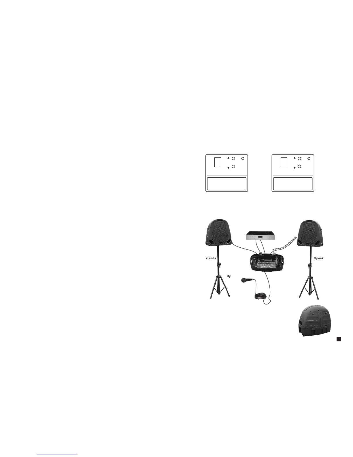
8. Ap plicatio n:
Left c hanne l outpu t Righ t chann el outp ut
9
m
e
t
e
r
s
s
p
e
a
k
e
r
l
i
n
k
c
a
b
l
e
s
CD
COM BO150 1 0" COM BO150 1 0"
Spe aker st andsSpe aker st ands
Dyn amic Mi croph one
6
m
e
t
e
r
s
s
p
e
a
k
e
r
l
i
n
k
c
a
b
l
e
s
5
(1) PA system own digital effect processing / digital delay
(2) Use up/ down arrow direction button to choose the effect you need
(4) Set the level in need
·the digital effect processing / digital delay
PEAK
POWER
UP
DOWN
DIGI TAL EFFEC T PROCE SSOR SYS TEM
4-Roo m3
5-Pla te1
6-Pla te2
7-Pla te3
0-Hal l1 1-Hal l2 2-Room1 3-Room2
8-Cho rus
9-Fla nge
A-Del ay1
B-Del ay2
C-Cho rus/R oom1
D-Cho rus/R oom2
E-Vocal C ancel
F-Rot ary Spe aker
(3) Whirl the switch clockwise in order to turn on the effect in this track
PEAK
POWER
UP
DOWN
DIGI TAL EFFEC T PROCE SSOR SYS TEM
0-12. 3ms 1-24. 6ms 2-23. 9ms 3-49. 2ms
4-61. 4ms
D-172 ms
A-135 .2ms
7-98. 3ms
5-73. 7ms
E-184 .3ms
B-147.5ms
8-110 .6ms
6-86m s
C-159 .7ms
F-196 .6ms
9-122 .9ms
Page 4
1. The main characteristic:
1) Stereo output 75W/4Ω×2(RMS)
2) 1/4" phone Jack (front panel)
3) 4 channels MIC input XLR connector
4) Stereo (CD/ tape) input with level control (front panel), 1/4" input phone Jack
Once the stereo signal connects the microphone, it will automatically cut off
the signal
5) Every channel with treble and bass volume control reverberation and level
control
6) The main volume in the front panel
7) Inside reverberation effect
8) Inside DSP effect / Digital delay
9) Inside power supply with switch
10) Five band diagrammatic equalizer with sound feedback monitor
11) Good 60 mm course attenuator and enclosed regulation resistance
2. Characteristic:
10" two pass filter
Power:100W
Impedance:4Ohm
Frequency Response:60Hz-20KHz
Sensitivity:94dB
Crossover frequency:4KHz
output power: 75W/4Ω×2
Frequency Response: 20Hz-20KHz≤1dB
THD: 20Hz-20KHz≤0.1%
Equivalent input noise level: ≤-114dB
Channel equalizer: alt: ±15dB
Bass: ±15dB
Power supply: 120VAC, 60Hz 200VA
230VAC, 50Hz 200VA
3. The main technical parameter:
4 1
7. setting installation
(1) After turning on the power supply, turn up the main
channel slowly. The best effect is at 6 positions.
(2) Set the level for well connected channel (channel 1
is MIC. Channel 2 is guitar. Channel 3 is C D player)
(3) Adjust the gain attenuator in every channel
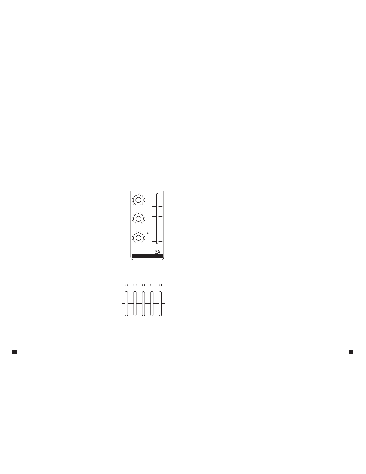
(4)Change tone in every channel by 2 band equalizer
(5) Clockwise whirl can increasethe sound-surroun d
ambiance of the tone. it will be decreased in anticlo ckwise direction
0510
REVE RB
-100+10
TREB LE
-100+10
BASS
10
9
8
7
6
5
4
3
2
1
0
GAIN
CHA NNEL 1
·Adjustable diagrammatic equalizer
(1) Mixer with 5 band diagrammatic equalizer
(2) Adjust the main track tone balance after organ-
izing the signal in all channels.
(3) Increase or attenuate 12 d B in every equalizer
(4) Move the slide bars to“ +” direction to increase
the signal in the frequency range. Otherwise it
is attenuation. In this way it can decrease th e
feedback from the different frequency range.
+12
+6
0
-6
-12
+12
+6
0
-6
-12
LOW LOW/ MID MID HIGH/ MID HIGH
(1) After finishing the above installation you can turn on the power supply
(2) make sure the mixer power supply is in closed state before you turn on the
power supply
(3) Connect the standard IEC power supply plug to the socket in the wall and
also connect the power supply
(4) make sure that all of the attenuator gain is at the smallest position ( every
channel including the main channel)
(5) Turn on the power supply switch at the back of the mixer.
·Connect the power supply
Page 5
MIC
LINE IN
0510
REVERB
-100+10
TREBLE
-100+10
BASS
10
9
8
7
6
5
4
3
2
1
0
GAIN
CHANNE L 1
MIC
LINE IN
0510
REVERB
-100+10
TREBLE
-100+10
BASS
10
9
8
7
6
5
4
3
2
1
0
GAIN
CHANNE L 2
MIC
LINE IN
0510
REVERB
-100+10
TREBLE
-100+10
BASS
10
9
8
7
6
5
4
3
2
1
0
GAIN
CHANNE L 3
0510
REVERB
-100+10
TREBLE
-100+10
BASS
10
9
8
7
6
5
4
3
2
1
0
GAIN
CHANNE L 4
0510
REVERB
-100+10
TREBLE
-100+10
BASS
10
9
8
7
6
5
4
3
2
1
0
GAIN
CHANNE L 5
+12
+6
0
-6
-12
+12
+6
0
-6
-12
LOW LOW/ MID MID HIGH/ MID HIGH
PEAK
POWER
UP
DOWN
DIGITAL EFFECT P ROCES SOR SYST EM
4-Room3
5-Plate1
6-Plate2
7-Plate3
0-Hall1 1-Hall2 2-R oom1 3- Room2
8-Chorus
9-Flange
A-Delay1
B-Delay2
C-Chorus/Roo m1
D-Chorus/Roo m2
E-Vocal Cancel
F-Rotary Spea ker
CH.1 CH.2 CH.3 CH.4
MIC IN
STEREO
LEFT/MONO RIGHT
CH.5
CD
IN
TAPE
OUT
L R
MODE
MONO
STEREO
10
9
8
7
6
5
4
3
2
1
0
MASTER
L
R
150 WATTS POWERED MIXER
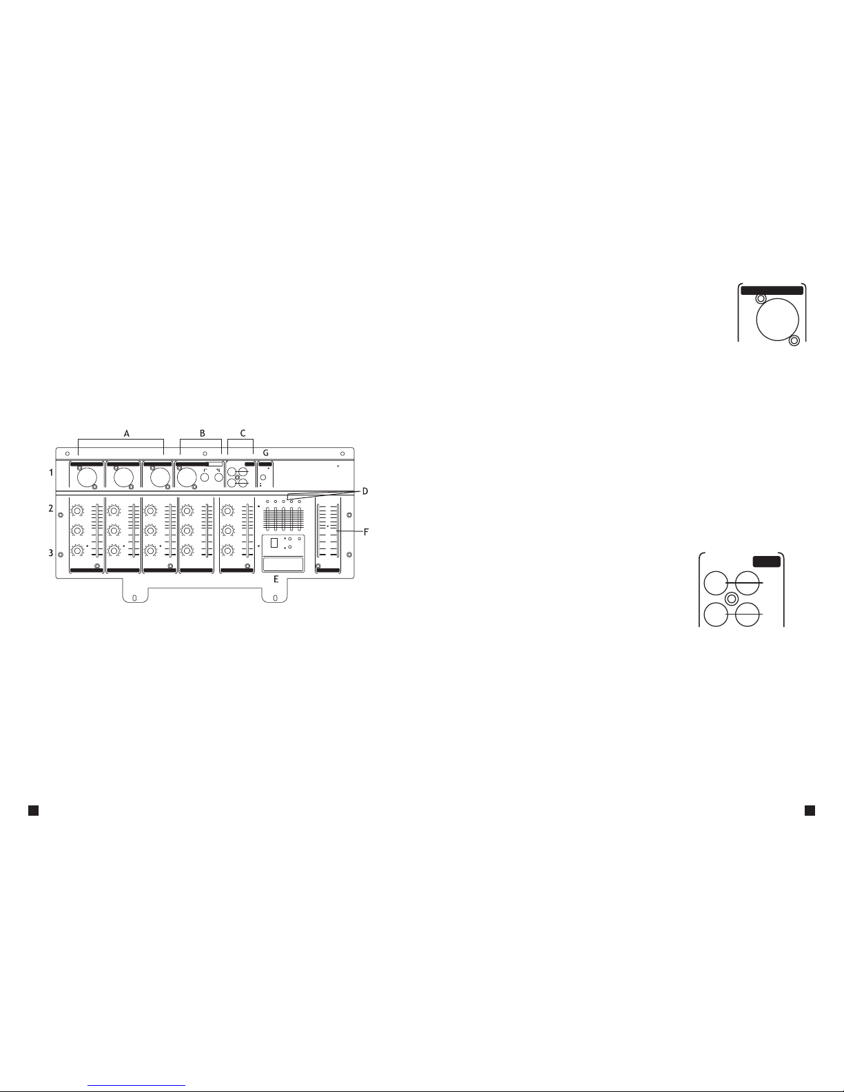
5.Fu nction int roduc tion:
A. Channel1-3: mono Combo (XLR and 1/4″double service phone Jack) input
plug hole
1. Combo input plug hole
2. Reverberation control knob
3. Treble and bass volume control
4. Channel gain attenuators
B. Channel4. Phone balanced input (XLR) and R, L channel stereo input track
C. channel5. CD input with RCA socket and TAPE output
D. diagrammatic equalizer
E. digital effect processing panel / digital delay
F. main volume attenuator
G. stereo/mono channel switch
(2) Take out the speaker stands, adjust to the needed height, and make sure
the ground is flat enough to connect firmly
(3) Mount the speak cabinet on the stands before the audience .keep the spe-
aker cabinet away from microphone in order to avoid echo
(4) Connect the speaker cabinet to the mixer in the plastic jacket and ma ke
sure left channel in speaker cabinet is connected to the left channel in the
mixer, the same as the right channel.
CH. 5
CD
IN
TAPE
OUT
L R
(1) Choose dynamic microphone. Because of this PA system without phantom
power, it can not work with any microphone needed phantom power, such
as dynamic microphone and so on.
(2) Choose suitable microphone or you choose
dynamic microphone by yourselves.
Choose suitable cables with XLR connector
to connect microphone to any channel.
·Microphone installation
(1) Connect CD/TAPE player to channel 5 with RCA connector
(2) Connect L and R to corresponding mixer port
(3) Adjust tone. Gains and reverberation by CD channel
·CD player installation
3
9 meters speaker link cables 2 PCS
Speaker stands 2 PCS
Dynamic Microphone 1 PCS
6 meters microphone link cables 1 PCS
Fuse Φ5x20mm T 3AL 2 PCS
4. Accessory:
6. Installation introduction
·Speaker cabinet installation introduction
(1) Take out the speaker cabinet and then connect them
MIC
LINE I N
CH. 3
2
 Loading...