

Page 1
Smart Ring
ORIGINALITY DESIGN SMART - AND BEAUTIFUL
QUICK GUIDE
Page 2

功能介绍Functions
Remote wake-up
The doorbell will be in a sleep mode to save power; you can have a preview
in App and have a remote wake-up to monitor after 3-4 Seconds.
Full-duplex audio
When the visitor push the doorbell button, you will get a call. You can see
and hear the vistor in your App from the doorbell if you answer.
PIR
When the doorbell detects someone stopping by, it sends an alarm message
to your cell phone.
Low battery alarm
You can set a low-battery alarm threshold on your phone App. The threshold is
set to a minimum of 10% and a maximum of 50%. When the battery power of
the doorbell is lower than the set threshold, the App will have a reminder.
Battery Lock
After battery box connected ,it will be locked immediately. User have to unlock
the battery box in the App setting page to if want to take out the battery box,only
30 seconds allowed.
Shared device
The doorbell device can be shared with friends, and friends can also preview
online. There is no limit to the number of sharing devices, but only 6 accounts
are supported for online preview at the same time.
1
Page 3
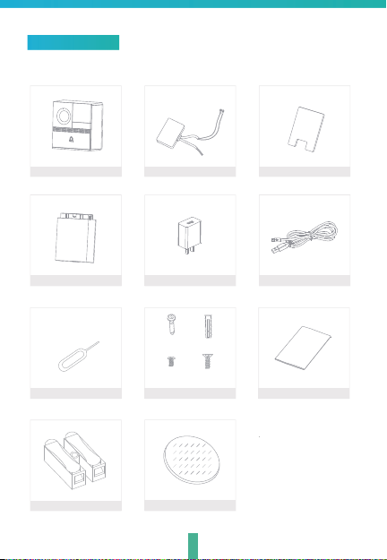
What's in the box
Consult the checklist below for all components.
Battery box
Wire nuts
Power converter
Power adapter
B x 4
A x 4
C x 2
D x 1
Screws(4 kinds) I/MPin
Adhesive table
2
MylarSmart Ring
USB cable
Page 4
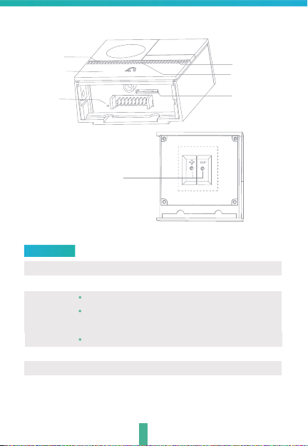
Microphone
Doorbell button
Reset 1
Description
Power Port
Doorbell button
Status light
Microphone
SD card slot
Reset1
Status light
Speaker
SD card slot
External
power port
Back of doorbell
DC 5V±10%,use the screws to fix the power converter
Press the button to activate the doorbell
Red light solids on: the camera network is abnormal
Red light blinking: awaiting WiFi connection, or currently
connecting (faster blinking)
Blue light solids on: camera running correctly
Captures sound for your video
Supports local SD Card storage (Max.128G)
Press and hold on for 5 seconds with pin to reset the doorbell
(unable to unbind the bell from account)
3
Page 5
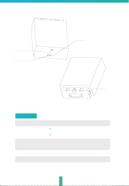
Reset 2
Charging
indicator
Mini USB
Description
Mini USB
Charging indicator
Reset 2
Bayonet lock
Battery capacity 6000mAh (Two 18650 lithium-ion batteries)
DC5V±10%,USB power supply
Red indicator solids on: battery is charging
Blue indicator solids on: finishing charging
Tap reset button for 5 seconds to factory
reset (it will not unbind the device)
Lock the battery box through bayonet lock
4
Bayonet
lock
Page 6
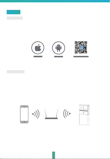
Connect
Download
Smart Life is available for both iOS and Android OS. Rearch the name
'Smart Life'in App Store or Android Market, or scan the QR-Code to
download the App.
·Support
IOS
Android
Dowoload App(IOS&android)
Set up router
This device only supports 2.4GHz frequency band router, does not support
5GHz frequency band router, please set the relevant parameters of the router
before WiFi configuration, WiFi passwords do not include special characters
such as ~!@#$%^&*(). When the device is configured in WiFi, the mobile phone
and device are as close as to the router, which can speed up the configuration
of the device.
Please keep network available
4
Page 7

Registration process
Step 1 Open the Smart Life App, click "Register", read the "Privacy Policy"
and click "Agree" .
Step 2
input a legal and valid Mobile number or Email address and click
"Continue". Input Verification Code, then log in the app.
5
Page 8

QR Code Configuration
Getting started
1. Please follow the instructions and make sure the password is inputed
correctly.
2. One device can only be added with one App account, if the device
has been added with another account already, then it can
to any another account again.
3.The device will be unbind from previous account after been deleted from
App. Further ,the device will be resetted automattically once from blue
light to red light.
Process
Step 1 Open the Smart Life App, click "+" or "Add Device". Then select "All"
on the "Select Device Type" page.
Step 2 Select "Security Camera". Power the device on and make sure the
indicator is flashing quickly or a prompt tone is heard.
7
'
t be added
Page 9

Step 3 Input WiFi password and click "Confirm", scan the QR Code with
a device. (You can change the network connection)
About 20cm
8
Page 10

Step 4 Click "I heard the beep" when the device comes out "dong dong
dong". And you can complete the configuration about 30s.
Step 5 The device is added, and the device nickname can also be
changed in this interface.
Notice:After the device configured successfully, it will be automatically
locked.Motor in the battery box will make a sound.Click "Click
to Unlock the Battery"first before unplug the battery.
9
Page 11

FAQ
Q: In the network process, the process bar is always not 100%, add
failure?
A: This camera only supports 2.4GHz WiFi router, please make sure you
are using a 2.4GHz WiFi router.And confirm the WiFi password again.
Q: Repeated additions are failures?
A: After adding a failure, it is recommended to restart the device or power
off, and then try to add again.
Q: The device cannot be previewed properly?
A: Check whether the network is normal, you can place the camera close
to the router, and if not, it is recommended to reset the device and add
it again.
Q: How to cut the camera network to another router?
A: First remove and reset the device on the App and then configure the
device again by the App.
'
Q: Why I can
A: Please confirm that the App has been running on the phone, and the
relevant reminder function has been opened;Message notification and
authority confirmation in the mobile phone system have been opened.
Q: Why doesn't the device identify the SD card?
A: It is recommended to plug in SD card after power cut. Confirm whether
the SD card is normally available and the format is FAT32. And the TF
card can
t get the notifications with my cell phone App?
'
t be identified when the internet environment is not good.
10
Page 12

Unlock
Step 1 Click "...", enter the "Setting" page and click "Basic Feature Settings".
Step 2 Enter the "Basic Feature Settings" setting page and click "Unlock the
Battery" to unlock it automatically. When the motor is finished, the
battery box can be pulled out.
12
Page 13

安装Install
Installation of Power supply mode
output-
inputcable
cable
Step 2 Remove the bottom cover and bracket of the
doorbell host and lead the output terminal.Connect
to the power interface on the back of the doorbell
host.Note: red lead connects the power "+", black
connects the power "-".
8~24
V AC
Step 1 Each input-cable (AC
8~24V) connect to the wires
which come out of the wall.
Step 3 Remove the double-sided adhesive
on the back of the mylar sheet.Cover the
position of the power interface on the back
of the doorbell host.
Warning:Don’t fall down during using
Mylar
Red lead
Step 4 Use the marker to draw the
positions of the 4 screw holes on t
he wall surface to be installed.
13
Black lead
Step 5 Screw 4 expansion screws into the
newly marked position.
Page 14

Step 6 Fix the mounting bracket to
the wall.
Step 7 Install the bottom door of the doorbell
main unit and fix it with screws.
14
Step 8 Pull the power cable from the
center hole of the bracket and slowly
insert the doorbell into the door as
shown in the above figure (be careful
not to catch your finger).
Page 15

Install the device in battery-powered mode
Step 1 Remove the doorbell bottom
cover and bracket as shown in the
figure
Step 3 Screw 4 expansion screws into the
newly marked position
Step 2 Use the marker to draw 4 screw
holes on the surface of the wall to be
installed
Step 4 Fix the mounting bracket to
the wall
15
Page 16

Step 5 Snap the doorbell into the bracket
Step 6 Align the battery box with the bayonet lock, and push the battery box
into doorbell.
16
Page 17

FCC Warning
This device complies with part 15 of the FCC rules. Operation is subject to the following two
conditions: (1) this device may not cause harmful interference, and (2) this device must accept
any inte rference received, including interference that may cause undesired operation.
Changes or modifications not expressly approved by the party responsible for compliance could
void the user's authority to operate the equipment.
NOTE: This equipment has been tested and found to comply with the limits for a Class B digital
device, pursuant to part 15 of the FCC Rules. These limits are designed to provide reasonable
protection against harmful interference in a residential installation. This equipment generates
uses and can radiate radio frequency energy and, if not installed and used in accordance with the
instructions, may cause harmful interference to radio communications. However, there is no
guarantee that interference will not occur in a particular installation. If this equipment does
cause harmful interferenceto radio or television reception, which can be determined by turning
the equipment off and on, the user is encouraged to try to correct the interference by one or
more of the following measures:
• Reorient or relocate the receiving antenna.
• Increase the separation between the equipment and receiver.
• Connect the equipment into an outlet on a circuit different from that to which the receiver is
connected.
• Consult the dealer or an experienced radio/TV technician for help.
Radiation Exposure Statement
This equipment complies with FCC radiation exposure limits set forth for an uncontrolled
environment. This equipment should be installed and operated with minimum distance 20cm
between the radiator and your body.
 Loading...