

Page 1
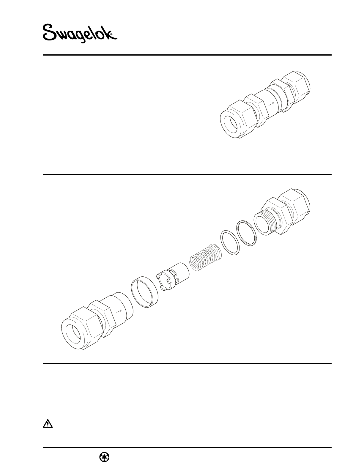
O-ring
Outlet Body
Backup Ring
Spring
Identification Ring
Poppet
Inlet Body
End Connection
End Connection
Body Hex
Body Hex
MS-CRD-0064
Revision 1 6-00-CP
XS Series Excess Flow Valve
Service Instructions
Contents
• Component Identification . . . . . . . . . . . . . . . 1
• Tool Requirements . . . . . . . . . . . . . . . . . . . . 2
• Installation . . . . . . . . . . . . . . . . . . . . . . . . . . 2
• Testing . . . . . . . . . . . . . . . . . . . . . . . . . . . . 2
• Kit Contents . . . . . . . . . . . . . . . . . . . . . . . . . 3
• Maintenance . . . . . . . . . . . . . . . . . . . . . . . . 3
• Troubleshooting . . . . . . . . . . . . . . . . . . . . . . 6
Valve is shown with Swagelok®tube fitting end connections. These instructions also apply to XS series
valves with pipe ends and with VCR®and VCO®face-seal fitting end connections.
Component Identification
Definitions
Statements and symbols are used in this document
to identify safety concerns. Read the definitions
below before performing the service instructions.
This symbol indicates cautionary
information.
Caution: Indicates a potentially hazardous
situation. It may also be used to
alert against unsafe practices.
Notice: Indicates a statement of company
policy directly or indirectly related to
the safety of personnel or protection
of property.
Page 2
For Body
Hex
Qty. (1)
2
MS-CRD-0064
Revision 1 6-00-CP
Tool Requirements
Tool size depends on the nominal end connection
size and style. See the table below.
Other Tools
Torque wrench rated to 200 in·lb (22.6 N·m).
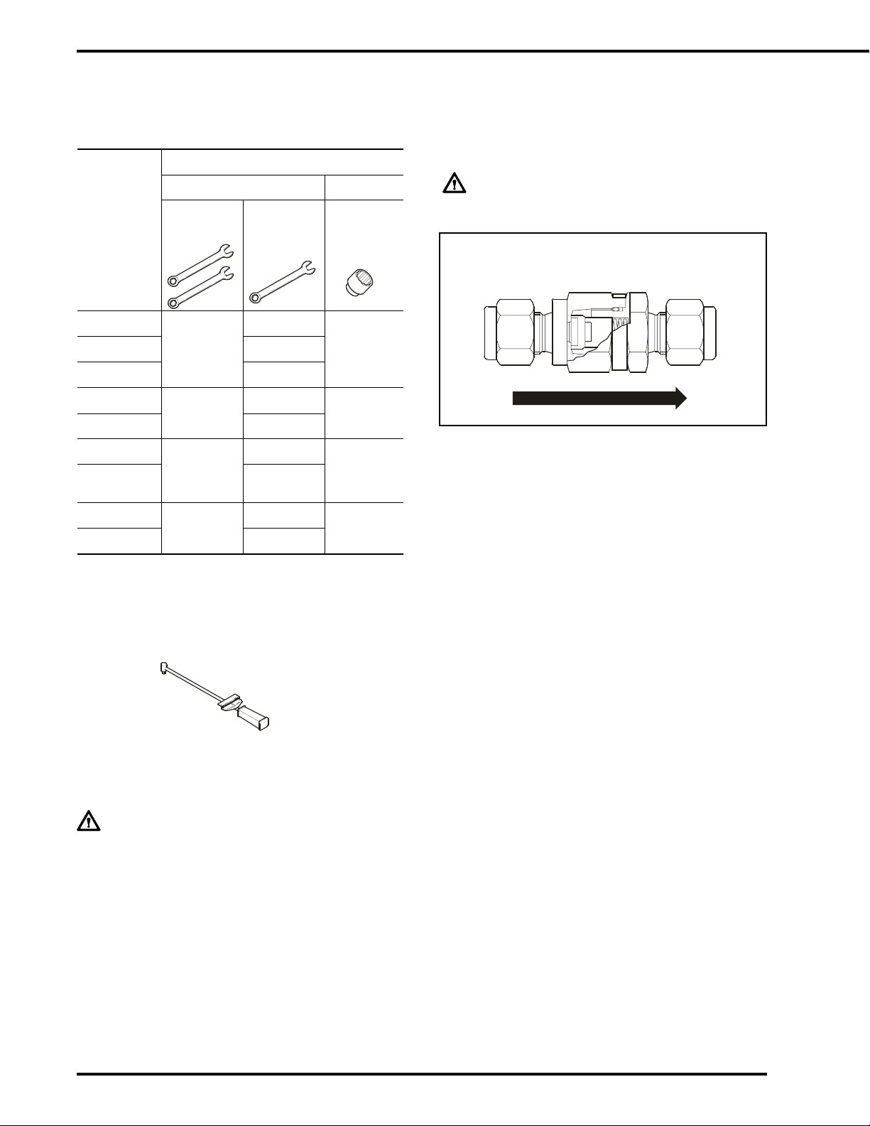
Installation
1. Refer to the flow direction arrow on the excess
flow valve and install the valve in the
correct orientation.
IMPORTANT:
Verify proper flow direction when installing.
Inlet
Outlet
2. For valves with Swagelok tube fittings or VCO
®
or VCR®fittings, following the specific fitting
assembly instructions.
3. For valves with pipe fittings or straight thread
fittings, follow standard industry practices.
The flow direction verification card included
with the valve shows the proper flow direction.
Testing
1. Operate at normal flow rate. Create maximum
flow surges. Valve must remain open in both
instances.
2. Vent system line to simulate a break. Valve
must trip (close).
• If valve trips closed, proceed to step 3.
• If valve does not trip closed, replace the
spring with one of the lower-flow springs.
Repeat the Testing procedure.
3. Perform reset test by venting system to trip
valve. Close upstream or downstream valve to
allow the valve to reset. Valve must open and
allow normal flow.
4. Test the valve to ensure there is no leakage to
the atmosphere.
Nominal
End
Connection
Size
Tool Size and Quantity
Wrenches Socket
For Body
Hex Qty. (2)
For End
Connection
Qty. (1)
1/8 in.
11/16 in.
7/16 in.
11/16 in.
1/4 in. 9/16 in.
6 mm 14 mm
3/8 in.
1 in.
11/16 in.
1 in.
1/2 in. 7/8 in.
1/2 in. FNPT
11⁄16 in.
11⁄16 in.
11⁄16 in.
1/2 in.
BSP/ISO
11⁄16
in.
8 mm
1 in.
16 mm
1 in.
12 mm 22 mm
Caution:
Before servicing any installed valve you
must:
• depressurize the system
• purge the valve.
Flow Direction Verification Card
Page 3

3
MS-CRD-0064
Revision 1 6-00-CP
Spring Kit Contents
Standard-Flow
Spring
Medium-Flow
Spring
Low-Flow
Spring
XX GPM
XX GPM
XX GPM
Backup Ring
O-ring
One Set of Three Labels
GPM = gallons per minute (U.S. gal/min).
Body Hex Wrenches
Maintenance
Disassembly
1. Remove the excess flow valve from the
system.
2. Separate the inlet body from the outlet body.
4. Remove the spring.
Inlet Body
7. Remove the identification ring.
5. Remove the O-ring.
6. Remove the backup ring.
Outlet Body
3. Remove the poppet.
Page 4

4
MS-CRD-0064
Revision 1 6-00-CP
Reassembly
Outlet Body
1. Place the backup ring on the outlet body.
2. Lubricate the O-ring with a compatible
lubricant.
3. Slide the O-ring over the threads against the
backup ring.
4. Select the preferred replacement spring from
the table below.
5. Insert the spring, large end first, into the body.
6. Insert the poppet over the spring.
Body
threads
7. Lubricate the body threads with a systemcompatible lubricant
Nominal
End
Connection
Size
Spring
Nominal Flow, U.S. gal/min (L/min)
Standard
Flow
Medium
Flow
Low
Flow
1/8 in.
1/4 in.
6mm
XS4 XS4-3 XS4-1
5 (18.9) 3 (11.3) 1 (3.7)
3/8 in.
8 mm
XS6 XS6-6 XS6-3
9 (34.0) 6 ((22.7) 3 (11.3)
1/2 in.
12 mm
XS8 XS8-6 XS8-3
13
(44.2)
6
(22.7)
3
(11.3)
Page 5

5
MS-CRD-0064
Revision 1 6-00-CP
Inlet Body
8. Place the identification ring on the body.
9. Select the trip point label that matches the
replacement spring. Place the label on the
identification ring.
11. Tighten the valve bodies.
10. Thread the outlet and inlet bodies together.
Notice:
Do not pinch the O-ring and backup ring
between the outlet and the inlet bodies
during assembly.
The O-ring must fit tightly into the inlet body.
Tighten the
body halves to
approximately
200 in.·lb
(22.6 N
·m)
Body Hex Wrench
Body Hex
Socket
12. See Installation and Testing sections.
Page 6

6
MS-CRD-0064
Revision 1 6-00-CP
VCR, VCO, Swagelok — TM Swagelok Co.
© 2000 Swagelok Company
Safe Product Selection
When selecting products, the total system design
must be considered to ensure safe, trouble-free
performance. Function, material compatibility,
adequate ratings, proper installation, operation, and
maintenance are the responsibilities of the system
designer and user.
Caution: Do not mix or interchange parts with those
of other manufacturers
Symptom Possible Causes Corrective Action
Valve trips during
normal operation
Flow surges higher than expected. Evaluate a smaller valve.
Evaluate a lower trip range spring option.
Valve trips at
normal flow after
being in service for
some time.
Poppet openings are plugged. Clean or replace poppet.
Flush or blow down regularly.
Clean on a regular preventive maintenance
schedule.
Valve does not trip
at high flow
Valve is too large. Evaluate a smaller valve.
Evaluate a lower trip range spring option.
Low system pressure. System pressure must be greater than
trip pressure.
Evaluate a lower trip range spring option.
Poppet is stuck. The parts are contaminated. Clean
the parts thoroughly. Replace the damaged
parts.
Service regularly.
The parts are corroded. Replace corroded
parts. Select a compatible material.
Valve does not
reset itself
Bleed passage on
poppet is plugged.
The parts are contaminated. Clean
the parts thoroughly. Replace the
damaged parts.
Service regularly.
The parts are corroded. Replace corroded
parts. Select a compatible material.
Troubleshooting
Bleed
passage
 Loading...