

Page 1
A60 Fire / S60 Steam Series Ball Valves
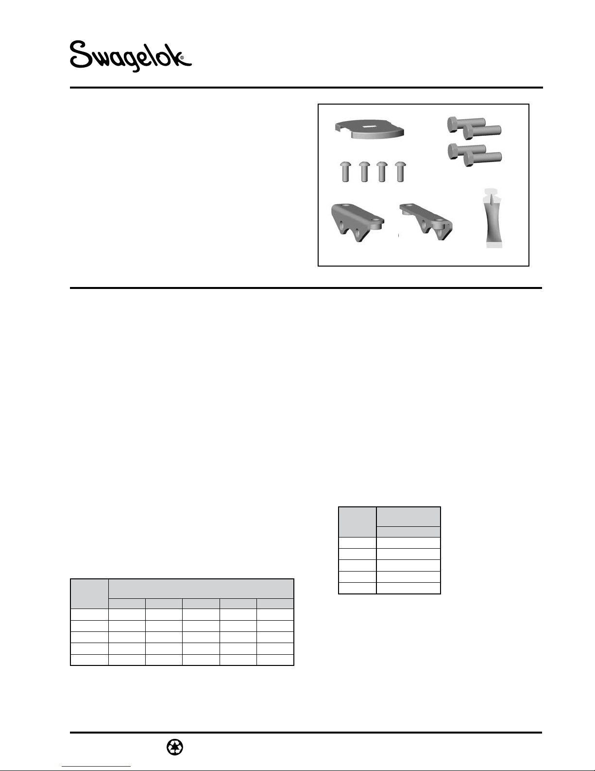
Kit Contents
• Panel Mount Brackets (2)
• Cap Screws (4)
• Bolts (4)
• Panel Mount Cover (except 62 series with oval handle)
• Lubricant with MSDS sheet
• Assembly Instructions
Maximum Panel Thickness
62 series 0.188 in. (4.77 mm)
All other 60 series 0.25 in. (6.35 mm)
Assembly Instructions
Refer to the illustrations on page 2 for a 62 series and a
65 series steam ball valve.
1. Loosen and remove the top four body bolts from the
valve. Do not loosen the remaining (4) bolts.
2. Loosen and remove stem nut, stem spring, name-
plate, stop plate, handle, and grounding spring
from valve stem.
3. Position one of the panel mount brackets against
the flange so the more closely spaced pair of holes
lines up with the holes in the flange.
4. Lubricate the (4) bolts with the lubricant provided.
Install (2) bolts through the holes in the bracket,
flange, and into the body.
5. Position the other panel mount bracket against the
other flange so the more closely spaced pair of holes
lines up with the holes in the flange. Note: The tab
with the threaded hole(s) should point away from the
valve stem.
6. Install the other (2) bolts through the holes in the
bracket, flange, and into the body. Tighten the bolts
(4) according to the table below.
Torque Values
Valve
Series
S62 5.0
A63 / S63 10 (1.1) 20 (2.3) 40 (4.5) 150 (17.0) 150 (17.0)
A65 / S65 25 (2.8) 50 (5.7) 100 (11.3) 300 (33.9) 300 (33.9)
A67 / S67 35 (4.0) 75 (8.5) 150 (17.0) 400 (45.2) 400 (45.2)
A68 / S68 40 (4.5) 100 (11.3) 200 (22.6) 600 (67.8) 600 (67.8)
1st Pass 2nd Pass 3rd Pass 4th Pass 5th Pass
(0.57) 10 (1.1) 20 (2.3) 40 (4.5) 40 (4.5)
in.·lb (N·m)
Panel Mount Instructions
Panel Mount Cover
Bolts (4)
Cap Screws (4)
Panel Mount Brackets (2)
7. Drill mounting holes in panel. See the diagram and
table on page 3 and / or use template on
page 4.
Note: For 62 series in a horizontal piping system,
turn template 90° to drill holes.
8. Line up the panel mounting holes with the mounting bracket tabs. Use the cap screws to fasten the
valve assembly to the panel.
9. Reinstall the grounding spring, handle, and stop
plate. Install cover plate.
Note: 62 series uses a cover plate with lever style
handle only.
10. Reinstall the stem spring, and stem nut. Tighten
the stem nut to the value shown below.
Note: 62 series does not use a stem spring.
Torque Values
Valve
Series
S62 25
A63 / S63 50 (5.7)
A65 / S65 100 (11.3)
A67 / S67 150 (17.0)
A68 / S68 150 (17.0)
in.·lb (N·m)
1st Pass
(2.8)
Lubricant
MS-INS-S60PMK
Revision 2 09-10
Page 2

2
MS-INS-S60PMK
Revision 2 09-10
Cover plate
Handle /
stop plate
Cap screws
Panel
62 Series Ball Valve
Stem nut
Grounding spring
(2)
Panel
mounting
holes (2)
Panel mount
bracket (1)
Top
body
bolts
(2)
Flange
Body
Stem
Panel mount
bracket (1)
Tab
Flange
Top
body
bolts
(2)
65 Series Ball Valve
Stem nut
Stem spring
Cover plate
Stop plate
Handle
Grounding spring
Top
body
bolts
(2)
2
Cap screws
Panel
Panel mount
bracket (1)
(4)
Flange
Body
Stem
Panel
mounting
holes (4)
Panel mount
bracket (1)
Top
body
bolts
(2)
Tab
Flange
Page 3

3
MS-INS-S60PMK
Revision 2 09-10
Panel Mounting Hole Diagram
C
1/2 C
A
Dimensions
Valve
Series
S62 1 3/8
A63 / S63 1 7/8 (47.6)
A65 / S65 2 3/8 (60.3) 3 1/2 (88.9)
A67 / S67
A68 / S68 5 (127)
A Dia. B Dia. C
(34.9) 1/4 (6.4) 1 29/32 (48.4)
3 5/8
(92.1) 13/32 (10.3)
in. (mm)
11/32 (8.7)
2 1/2 (63.5)
4 5/8 (118)
B (4) holes, except 62 series:
(2) holes diagonally
C
1/2 C
3
Page 4

Panel Mounting Hole Template
68 series
(13/32 in.)
65 series
(11/32 in.)
63 series
(11/32 in.)
63 series
(11/32 in.)
67 series
(13/32 in.)
62 series
(1/4 in.)
67, 68 series
(3 5/8 in.)
65 series
(2 3/8 in.)
62 series
(1 3/8 in.)
63 series
(1 7/8 in.)
68 series
(13/32 in.)
67 series
(13/32 in.)
65 series
(11/32 in.)
63 series
(11/32 in.)
62 series
(1/4 in.)
63 series
(11/32 in.)
68 series
(13/32 in.)
65 series
(11/32 in.)
67 series
(13/32 in.)
67 series
(13/32 in.)
65 series
(11/32 in.)
68 series
(13/32 in.)
Swagelok—TM Swagelok Company
© 2004, 2010 Swagelok Company
September 2010, R2
MS-INS-S60PMK
 Loading...