

Page 1
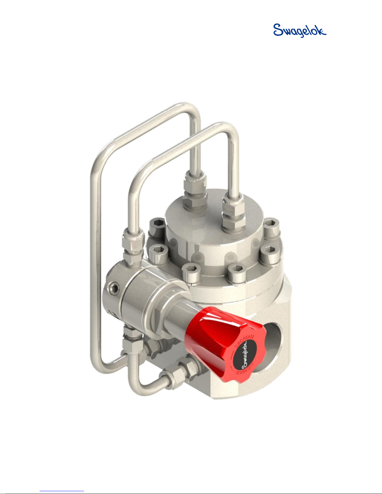
RD(H)10/15 Pressure-Reducing Regulator
User Manual
Read the complete manual before installing and using the regulator.
Page 2
2
Safe Product Selection
When selecting a product, the total system design must be considered to ensure safe, trouble-free
performance. Function, material compatibility, adequate ratings, proper installation, operation, and
maintenance are the responsibilities of the system designer and user.
WARNING
• Users must be trained and equipped for the handling, use and servicing of pressure
products and systems.
• Users must contact their gas or liquid supplier for specific safety precautions and
instructions.
• Gaseous media should be free of excessive moisture to prevent icing at high flow.
• Always wear the appropriate protective clothing, including safety glasses, gloves, etc. if
required.
• Follow the applicable safety and maintenance procedures.
• Obey specific local regulations.
• Do not exceed the maximum inlet and outlet pressure rating of the product or its
accessories.
• Operate within the temperature limits and any other conditions specified for the product.
• Do not drop or damage the product in any other way. This may negatively affect the
performance of the product which can cause the product to malfunction.
• Venting fluids and gases can be dangerous. Vent to a safe environment away from people.
Ensure adequate ventilation.
Page 3

3
Contents
Introduction ........................................................................................................................................................ 4
Overview.......................................................................................................................................................... 4
Standard Features ........................................................................................................................................... 4
Additional Options ........................................................................................................................................... 4
Oxygen Service ............................................................................................................................................... 4
Installation .......................................................................................................................................................... 5
Points of Attention Before Installation ............................................................................................................. 5
Installation ....................................................................................................................................................... 5
Dome Pressure Control ................................................................................................................................... 6
External Feedback .......................................................................................................................................... 9
Operation .......................................................................................................................................................... 10
Required Tools for Operation ........................................................................................................................ 10
Points of Attention Before Operation ............................................................................................................. 10
Adjusting the Set Pressure ............................................................................................................................ 10
Maintenance ..................................................................................................................................................... 11
Required Tools for Maintenance ................................................................................................................... 11
Points of Attention Before Removal from the System ................................................................................... 12
Removal from the System ............................................................................................................................. 12
Assembly Reference Data............................................................................................................................. 13
Disassembly .................................................................................................................................................. 18
Points of Attention Before Reassembly ......................................................................................................... 18
Reassembly ................................................................................................................................................... 19
RD(H)10 Series: Standard ............................................................................................................................ 19
RD(H)15 Series: Standard ............................................................................................................................ 19
External Feedback Option ............................................................................................................................. 19
Testing .............................................................................................................................................................. 20
Seat Leak Test .............................................................................................................................................. 20
Shell Leak Test .............................................................................................................................................. 20
Troubleshooting .............................................................................................................................................. 21
Page 4

4
Introduction
Overview
- The RD(H)10 and RD(H)15 series are dome loaded pressure reducing regulators designed for the
regulation of high pressure, high flow gases and liquids.
- For pressure and temperature rating information refer to the Pressure Regulators, RHPS Series catalog,
MS-02-430. Note that seat seal material selection can limit the regulator operational pressure at elevated
temperatures.
WARNING
Check that system pressures and temperatures do not exceed those stated on the regulator as
this could result in product failure.
Standard Features
- Bolted construction
- Stainless steel as standard
- Fully serviceable
- Diaphragm sensing
- Balanced poppet
- Pilot regulator
- Dynamic regulation
Additional Options
The regulator is available with the following options:
- External feedback to main regulator
- External feedback to pilot regulator
- Anti-tamper pilot regulator
Oxygen Service
- For more information about hazards and risks of oxygen enriched systems see the Swagelok Oxygen
System Safety technical report (MS-06-13).
- Cleaning and packaging to ensure compliance with product cleanliness requirements stated in ASTM G93
Level C is available. Refer to the Pressure Regulators, RHPS Series catalog, MS-02-430, for additional
information.
Page 5
5
Installation
CAUTION
Do not use the regulator as a shutoff device. A level of leakage across the regulator seat can
occur during normal operation.
Points of Attention Before Installation
This regulator can be equipped with a variety of different options. Before installing the regulator you should
fully understand the functions of the supplied options and the suitability of your particular regulator for the
intended application.
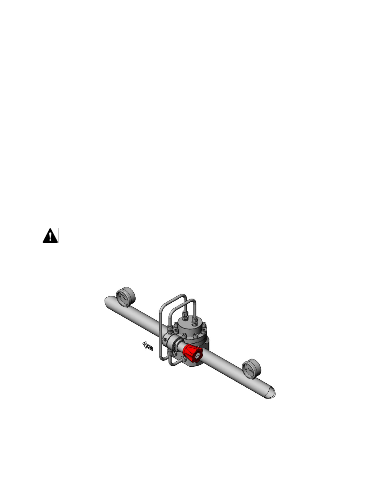
- The preferred mounting position of the regulator is horizontal with the dome facing upwards per Fig 1.
Alternative mounting positions may increase the risk of component wear.
- It may be necessary to remove the regulator from the system during maintenance or service. Ensure that
this is possible.
- The regulator is suitable for gases and liquids dependent on the options selected. For liquid applications
an integral pilot regulator should not be used. Ensure compatibility between the regulator’s materials of
construction and the system media.
- Swagelok recommends the use of a non-venting pilot regulator when the process media is hazardous or
toxic.
Installation
- Verify that the regulator, the connections and its accessories are undamaged.
- Verify that the regulator and its accessories are suitable for the system operating pressure and
temperature and have suitable connections.
- At the time of delivery any gauge ports may be plugged with blind fittings. Remove these and connect
gauges if desired.
- If inlet/outlet fittings are being used, assemble them to the regulator, per the manufacturer’s instructions,
prior to installing the regulator in the system.
CAUTION
Ensure all upstream tubing/pipework is clean and free from debris. Any swarf, lint, wire, etc. may
damage the regulator, resulting in a seat leak.
- Verify the flow direction of the system and mount the regulator accordingly.
- Securely make the appropriate connections to the regulator in accordance with the procedures
recommended by the connection manufacturer.
- Ensure that the tubing/pipework and the regulator are adequately supported and that there is no stress on
the connections.
- Upstream and downstream shutoff valves should be installed in the system to facilitate servicing,
maintenance and troubleshooting of the regulator.
WARNING
When using an RDH10 or RDH15 with an inlet pressure higher than 3625 psig (250 bar), a safety
valve must be installed in the outlet line to ensure the outlet pressure does not exceed 3625
psig (250 bar), which could result in product failure.
Page 6
6
Dome Pressure Control
The dome pressure of the regulator controls the outlet pressure. There are several methods available for
supplying and controlling the dome pressure.
- Integral pilot control. In this setup the dome loaded regulator comes supplied with a pilot regulator as
part of the assembly (Fig 1). The pilot regulator, fed from the system pressure, is manually operated to
control the dome pressure (Fig 2). This setup is not suitable for liquid applications.
- External dome control. In this setup the dome pressure is supplied from an independent source, such as
a cylinder or mains supply (Fig 3). This setup is suitable for liquid applications.
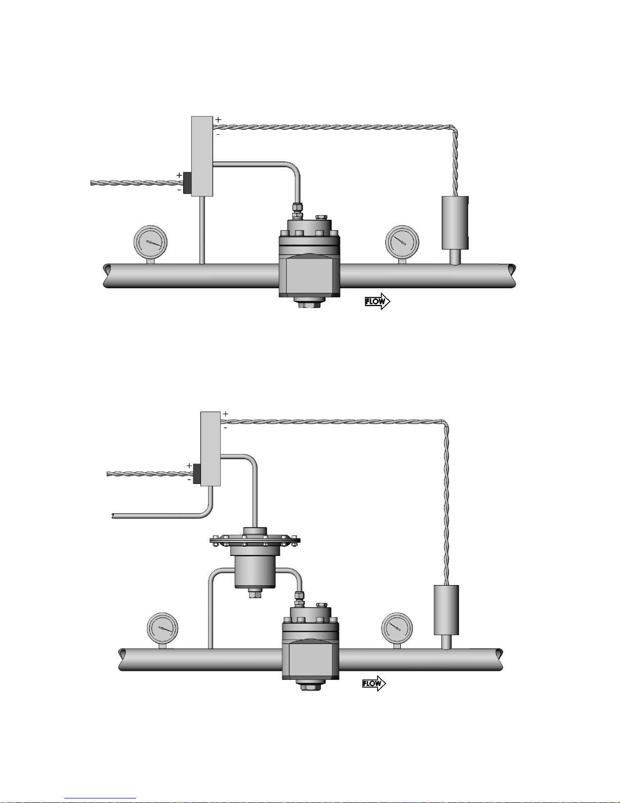
- Electronic control. In this setup an electronic pilot regulator, fed from the system pressure, is used in
conjunction with a pressure transducer to directly control the dome pressure (Fig 4). The outlet pressure
of the main regulator will be limited by the outlet pressure of the electronic regulator. This setup is not
suitable for liquid applications.
- Ratio control. In this setup a ratio pilot regulator, fed from the system pressure, is used to control the
dome pressure. The ratio pilot can be controlled by an electronic regulator and pressure transducer
combination (Fig 5) or by an external dome feed. The ratio pilot outlet pressure is proportionally larger
than its sensing pressure. This enables the main regulator to achieve full outlet pressure while being
controlled from a low pressure supply. This setup is not suitable for liquid applications.
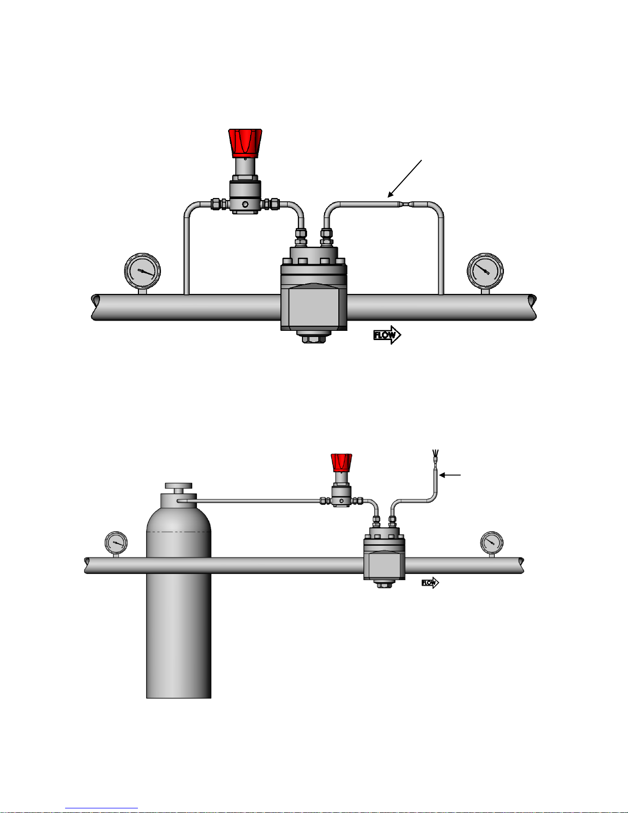
The best performance will be achieved by allowing a small flow to continuously pass through the pilot
regulator. This flow can either be vented through an orifice (Fig 3) or, in gas systems, fed back through an
orifice into the downstream piping (Fig 2). This is usually referred to as “dynamic regulation”.
NOTICE
It is not recommended to place a gauge on the dome to set or check the outlet pressure.
Because of forces in the regulator, the dome pressure will differ slightly from the outlet
pressure. Place a gauge in the outlet line to set or check the outlet pressure.
Integral Pilot Assembly
Fig 1
Page 7
7
Integral Pilot Control Schematic
Fig 2
External Dome Control Schematic
Fig 3
Pilot regulator
“Dynamic Regulation”
venting to the outlet line
Dome regulator
Pilot regulator
“Dynamic Regulation”
venting to atmosphere
Dome regulator
Cylinder or
mains supply
Page 8
8
Electronic Control Schematic
Fig 4
Ratio Control Schematic
Fig 5
Electronic
pilot regulator
4-20mA/0-10V
4-20mA/0-10V
Dome regulator
Pressure
transducer
Ratio regulator
Electronic
pilot regulator
4-20mA/0-10V
4-20mA/0-10V
Dome regulator
Pressure
transducer
Page 9

9
External Feedback
The purpose of external feedback is to provide a more accurate and stable regulation of the outlet pressure.
This is achieved by sensing the outlet pressure downstream of the regulator and feeding it back to the
regulator’s sensing element.
- The external feedback line is to be connected in a turbulence-free zone in the downstream piping, at a
maximum distance of 5x the outside diameter of the downstream tubing/piping (Fig 6).
- The tube size of the external feedback should be 3/8 in. or 1/2 in. or the metric equivalent.
CAUTION
When using a regulator with external feedback, ensure that the outlet line is connected to the
external feedback port before applying pressure to the regulator. Failing to do so may lead to
damage and non-functioning of the regulator and no pressure regulation will occur.
CAUTION
Never connect the external feedback line downstream of a shut-off valve. Doing so may lead to
damage and non-functioning of the regulator and no pressure regulation will occur.
External Feedback Schematic
Fig 6
Shutoff valve
Shutoff valve
Inlet
pressure
Dome
pressure
Outlet
pressure
Max. 5X O.D.
O.D
External feedback line
Page 10

10
Operation
Required Tools for Operation
No tools are required for changing the set pressure on a standard regulator.
Points of Attention Before Operation
CAUTION
The product can be hot or cold, depending on the environmental temperature and the process
media temperature. Take the necessary precautions before operating or touching the product.
- Stopping flow through the regulator by closing a downstream shutoff valve may result in a rise in outlet
pressure above the set pressure. This is usually referred to as “lock-up”. This phenomenon does not
indicate a problem with the regulator.
- A decrease of the flow rate may result in a rise of the outlet pressure. An increase of the flow rate may
result in a fall of the outlet pressure. This is usually referred to as “droop”. This phenomenon does not
indicate a problem with the regulator.
- A decrease of the inlet pressure may result in a rise of the outlet pressure. An increase of the inlet
pressure may result in a fall of the outlet pressure. This is usually referred to as “inlet dependency” or
“Supply Pressure Effect (SPE)”. This phenomenon does not indicate a problem with the regulator.
Adjusting the Set Pressure
- The set pressure is the desired outlet pressure of the regulator.
- To set the regulator, ensure that the supply pressure is greater than the required set pressure but does
not exceed the maximum rating of the regulator.
- The regulator must be able to flow in order for it to reduce the outlet pressure.
1. Partially open any downstream valve. This will allow minimal flow through the regulator when adjusting the
set pressure, reducing media consumption during this process.
2. Ensure there is zero pressure in the dome.
3. Steadily open the supply valve to allow inlet pressure to the regulator.
4. To operate the regulator, turn the pilot adjustment knob clockwise to increase the set pressure. Turn the
knob counterclockwise to reduce the set pressure.
5. To obtain the most accurate set pressure, final adjustment must be made while increasing the set
pressure. If the desired outlet pressure is exceeded, reduce the pressure below this value then increase
up to it.
6. Fully open the downstream valve to allow full flow during operation.
7. Once under flow conditions make any final set pressure adjustments per steps 3 and 4 if required.
NOTICE
The pilot regulator knob assembly is retained by a C-ring. When backing off the knob do not
attempt to continue to unwind the knob once it has stopped. Doing so may damage the C-ring.
Page 11

11
Maintenance
WARNING
Incorrect or improper repair or servicing of this product can cause serious personal injury and
property damage.
- All repairs, servicing and testing of this product must be performed by competent personnel.
- Following any maintenance of the regulator, it is recommended that the product be tested for operation
and leakage.
- The product should be checked periodically for proper and safe operation. It is the user’s sole
responsibility to determine the frequency of maintenance based on the application.
- To reduce maintenance related system downtime to a minimum, either during commissioning or normal
operation, Swagelok recommends having maintenance kits readily available on site. The need for
maintenance kits is particularly important during the commissioning phase of a system installation due to
residual assembly debris remaining in the system. Such debris can cause a seat leak in the regulator,
resulting in components needing to be replaced.
Required Tools for Maintenance
Smooth-jawed vise
Calibrated torque wrench up to
37 lbf·ft (50 N·m)
36 mm socket
Seat mounting tool:
RHPS-10-SEAT-TOOL
RHPS-15-SEAT-TOOL
Appropriate wrenches
for disassembling tube
fittings
Lubricant (included in kit):
WL-8①
Krytox® 240 AC②
8 mm hex drive
Liquid leak detector
C-ring pliers
① Standard cleaned assemblies
② ASTM G93 or SC11 cleaned assemblies
Table 1
Page 12

12
Points of Attention Before Removal from the System
- Swagelok recommends removing the regulator from the system for servicing and maintenance.
- Follow all local system safety and maintenance procedures when removing the regulator.
WARNING
Before removing a regulator from the system, to avoid personal injury, you must:
• Depressurize the system and dome.
• Purge the system to remove any residual system media left in the regulator.
• Always vent to a safe environment away from people and ensure there is adequate
ventilation.
CAUTION
Check if the process media is hazardous or toxic. If required, take the necessary safety
precautions to ensure a safe workspace and your personal safety.
CAUTION
The product can be hot or cold, depending on the environmental temperature and the process
media temperature. Take the necessary precautions before operating or touching the product.
Removal from the System
1. Isolate the regulator from all pressure sources by closing all appropriate upstream valves in the system.
2. With the pilot regulator set, open all appropriate downstream valves to allow pressure to vent from the
regulator.
WARNING
Ensure all pressure on the inlet, outlet and dome has been fully vented. The accidental release
of residual trapped pressure can cause serious personal injury.
3. Ensure appropriate lifting equipment is available to enable the regulator to be supported and handled
once disconnected from the system.
4. Ensure that any external dome feed and/or external feedback connection is disconnected.
5. Disconnect and remove the regulator from the system.
Page 13

13
Assembly Reference Data
Item
Component Name
Kit Type(s)
Torque
lbf·ft (N·m)
Recommended Lubrication
(included in kit per table 1)
1
Body plug
C1, C2
37 (50)
Lubricate threads
2
Body plug O-ring
B1, B2, C1, C2
3
Poppet spring
C1, C5
4
Poppet backup ring
A1①, A2①, B1, B2,
C1
5
Poppet O-ring
A1①, A2①, B1, B2,
C1, C2②
Lubricate
6
Poppet
A1, A2, B1, C1
7
Seat
A1, B1, C1
RD(H)10 - 7 (10)
Lubricate threads
RD(H)15 - 11 (15)
8
Seat O-ring
A1, B1, B2, C1
9
Body
N/A
10
Body plate
C1
11
Body plate outer O-ring
B1, B2, C1
12
Body plate inner O-ring
B1, B2, C1
Lubricate
13
Retaining ring
C1
14
Diaphragm plate
C1
15
Diaphragm
B1, B2, C1, C3
16
Dome plate
N/A
17
Dome
N/A
18
BSP blind plug O-ring
B1, B2, C1
19
Blind plug
N/A
NPT: 15 (20)
Wrap threads in 2 layers of
PTFE tape. Lubricate tape.
BSP: 26 (35)
Lubricate threads
20
Washer
E1
21
Cap screw
E1
22 (30)
Lubricate threads
22
Parallel gasket
B1, B2, C1
23
Bleed fitting (reduced
orifice)
N/A
Per manufacturer instructions
24
Tube fitting
N/A
Per manufacturer instructions
25
Bleed tube
N/A
26
Feed tube
N/A
27
Pilot regulator
N/A
28
Dome tube
N/A
① RD(H)10 series only
② RD(H)15 series only
Table 2
For more information on RHPS series maintenance kits, refer to the Pressure Regulators, RHPS Series
catalog, MS-02-430.
Page 14

14
RD(H)10 and RD(H)15 Series, Exploded View
Fig 7
Page 15

15
Integral Pilot Regulator Assembly, Exploded View
Fig 8
Page 16

16
RDH10 Series, Standard, Section View
`
Fig 9
Page 17

17
RD15 Series, External Feedback Option, Section View
Fig 10
Page 18

18
Disassembly
- The following instructions describe how to fully disassemble the regulator for the purposes of
maintenance and repair.
- Note that not all components listed appear in all regulator configurations.
- Only disassemble the regulator as far as is required to replace the components supplied in the
maintenance kit.
- Discard all components being replaced.
1. If present remove the feed tube (26), dome tube (28), bleed tube (25), and pilot regulator (27).
2. Remove the body plug (1), poppet spring (3), and poppet (6) from the body (9).
3. Remove the body plug O-ring (2), poppet O-ring (5) and, if present, poppet backup ring (4) from the body
plug (1) and poppet (6).
4. Using the seat insertion tool, remove the seat (7) and seat O-ring (8).
5. Remove the cap screws (21) to remove the dome (17), dome plate (16), diaphragm (15), and diaphragm
plate (14).
6. Remove the retaining ring (13) to remove the body plate (10). For external feedback regulators remove
the inner (12) and outer (11) body plate O-rings.
Points of Attention Before Reassembly
- Visually inspect all components for abnormal wear or damage. Replace components in case of doubt.
- All parts must remain clean and undamaged before starting assembly.
- Maintenance kit components will be supplied preassembled where practicable to aid reassembly.
- Swagelok recommends replacing all O-rings removed during disassembly.
- Swagelok recommends that dynamic O-rings should be lightly lubricated per Table 2.
NOTICE
All threaded components must be lightly lubricated per Table 2 before reassembly to avoid
galling of threads.
Page 19

19
Reassembly
RD(H)10 Series: Standard
1. Fit the body plate (10) into the body (9) and retain with the retaining ring (13).
2. Fit the seat O-ring (8) into the body (9) and ensure that it is seated all the way round.
3. Lightly lubricate the seat threads (7) then insert the seat (7) into the body (9) using the seat insertion tool.
4. Torque the seat (7) to 7 lbf·ft (10 N·m). Take care not to pinch the seat O-ring (8) or damage the seat (7)
with the tool.
5. Fit the poppet O-ring (5) and, if present, backup ring (4) onto the poppet. Ensure they are oriented
correctly per Fig 9.
6. Lightly lubricate the poppet O-ring (5) then insert the poppet (6) through the seat (7) and body plate (10).
Take care not to damage either the seat (7) or poppet (6).
7. Place the poppet spring (3) onto the poppet (6).
8. Fit the body plug O-ring (2) onto the body plug (1) and lightly lubricate the body plug threads.
9. Insert the body plug (1) into the body (9) over the poppet spring (3). Torque to 37 lbf·ft (50 N·m).
10. Place the diaphragm plate (14) onto the poppet (6).
11. Place the diaphragm (15) onto the diaphragm plate (14) and locate it in the body (9).
12. Place the dome plate (16) centrally onto the diaphragm (15) then cover with the dome (17). Orient the
dome ports per Fig 8.
13. Lightly lubricate the cap screw threads (21) then use them and the washers (20) to secure the dome (17)
to the body (9). Torque to 22 lbf·ft (30 N·m).
14. If present, install the feed tube (26), dome tube (28), and pilot regulator (27) into the ports on the inlet side
of the body (9) per Fig 8.
15. If present, install the bleed tube (25) into the ports on the outlet side of the body (9) per Fig 8. Note that
the bleed fitting (23) can be identified by its reduced internal orifice.
16. If present, make up all tube fittings (23, 24) per the manufacturers recommendations.
RD(H)15 Series: Standard
1. Follow steps 1 through 3 of the RD(H)10 series standard reassembly procedure.
2. Torque the seat (7) to 11 lbf·ft (15 N·m). Take care not to pinch the seat O-ring (8) or damage the seat (7)
with the tool.
3. Fit the poppet O-ring (5) into the body plug (1).
4. Follow steps 6 through 16 of the RD(H)10 series standard reassembly procedure.
External Feedback Option
1. Fit the inner (12) and outer (11) body plate O-rings onto the body plate (10). Lightly lubricate the inner
body plate O-ring (12).
2. For size 10 regulators follow the RD(H)10 series standard reassembly procedure.
3. For size 15 regulators follow the RD(H)15 series standard reassembly procedure.
Page 20

20
Testing
Swagelok recommends that the regulator be tested for seat and shell leakage to atmosphere. A well
performing regulator will not show any indication of leaking. If any evidence of a leak is identified this must be
rectified. Any damaged components must be replaced.
Seat Leak Test
1. Ensure there is sufficient supply pressure to the regulator to be able to perform the tests.
2. Ensure that there is zero pressure in the dome.
3. Maintain an inlet pressure of approximately 14.5 psig (1 bar) on the regulator and close the downstream
shutoff valve.
4. Monitor the outlet pressure. An increase in pressure over time indicates a seat leak.
5. Repeat the procedure with the highest inlet pressure applicable for the regulator and system.
Shell Leak Test
1. Maintain an inlet pressure of approximately 29 psig (2 bar) on the regulator and close the downstream
shutoff valve.
2. Increase the outlet pressure to approximately 14.5 psig (1 bar).
3. Using liquid leak detector, check for bubbles at the dome to body interface and the body plug to body
interface.
4. Repeat the procedure with the highest inlet and outlet pressure applicable for the regulator and system.
Page 21

21
Troubleshooting
Symptom
Cause
Remedy
The outlet pressure creeps up,
without adjusting dome pressure.
A damaged poppet or seat.
Replace the poppet and/or seat.
Leakage around the body plug.
A damaged O-ring.
Replace the O-ring.
Leakage between the body and
the dome.
A damaged diaphragm.
Replace the diaphragm.
Insufficient torque on the cap
screws.
Tighten the cap screws per Table 2.
Controlled pressure drops off
sharply even when the flow is
within regulator capabilities.
The system filter element is
clogged.
Replace the system filter.
The required outlet pressure
cannot be reached.
The inlet pressure to the
regulator is not high enough.
Ensure that the inlet pressure to the
regulator is equal to or greater than the
desired set pressure.
The outlet pressure rises too
much when going from a dynamic
to a static situation.
There is too much flow in the
dynamic situation.
A larger regulator or parallel regulator is
required.
Review application flow capacity and
contact your local Swagelok distributor.
The outlet pressure does not drop
when the pressure in the dome is
lowered.
The regulator is non-venting.
A shutoff valve in the outlet line must be
opened to reduce the outlet pressure.
The outlet pressure has changed
without adjusting the dome
pressure.
Changes to the inlet pressure
may result in changes to the
outlet pressure.
Maintain a constant inlet pressure to the
regulator. See “Points of Attention
Before Operation” about dependency.
Changes to the flow may
result in changes to the outlet
pressure.
Maintain a constant flow through the
regulator. See “Points of Attention
Before Operation” about droop.
No pressure regulation occurs
with an external feedback
regulator
The outlet line has not been
connected to the external
feedback port.
Connect the outlet line to the external
feedback port. See External Feedback
for installation details.
Table 3
Page 22

22
Page 23

23
Page 24

Warranty Information
Swagelok products are backed by The Swagelok Limited Lifetime Warranty.
For a copy, visit swagelok.com or contact your authorized Swagelok representative.
Swagelok, Snoop - TM Swagelok Company
Krytox – TM The Chemours Company
© 2018 Swagelok Company
July 2018, RevC
MS-CRD-0180
 Loading...