

Page 1
Power Supply
www.swagelok.com
This manual contains important information for the safe
and effective operation of the Swagelok® Welding System
M200 power supply. Users should read and understand its
contents before operating the M200 power supply.
User’s Manual
Page 2

2 M200 Power Supply User’s Manual
Page 3

Contents
Safety . . . . . . . . . . . . . . . . . . . . . . . . . . . . 5
Safety Summary . . . . . . . . . . . . . . . . . . . . . 5
Signal Words and Safety Alert Symbols
Used in this Manual . . . . . . . . . . . . . . . . . 5
M200 Power Supply Warning Label . . . . . . . . . . . 10
Referenced Documents . . . . . . . . . . . . . . . . . 11
Installation and Setup . . . . . . . . . . . . . . . . . . . 13
Description . . . . . . . . . . . . . . . . . . . . . . . . 14
Unpacking the M200 Power Supply . . . . . . . . . . . 16
Registration Information . . . . . . . . . . . . . . . . . 17
Tools and Accessories Required . . . . . . . . . . . 18
Electrical Requirements . . . . . . . . . . . . . . . 18
Setting up the M200 Power Supply . . . . . . . . . . . 19
Installing the Weld Head . . . . . . . . . . . . . . . . . 20
Setting Up the Gas Supply System . . . . . . . . . . . 21
Typical OD Shield / ID Purge Gas Supply System . . 21
Powering On the M200 Power Supply for the First Time 22
Powering Off the M200 Power Supply . . . . . . . . . . 22
Restarting the M200 Power Supply . . . . . . . . . . . 22
Using the Touch Screen . . . . . . . . . . . . . . . . . 23
User Interface . . . . . . . . . . . . . . . . . . . . 23
M200 Power Supply User’s Manual 3
Operation . . . . . . . . . . . . . . . . . . . . . . . . . . 25
Main Menu . . . . . . . . . . . . . . . . . . . . . . . . 25
Weld Screens . . . . . . . . . . . . . . . . . . . . . . 28
Performing a Weld . . . . . . . . . . . . . . . . . . 34
File Screens . . . . . . . . . . . . . . . . . . . . . . . 35
Program Screens . . . . . . . . . . . . . . . . . . . . 38
Weld Log Screens . . . . . . . . . . . . . . . . . . . . 39
Setup Screens . . . . . . . . . . . . . . . . . . . . . . 42
Remote Pendant . . . . . . . . . . . . . . . . . . . . . 47
Maintenance . . . . . . . . . . . . . . . . . . . . . . . . 48
Printer . . . . . . . . . . . . . . . . . . . . . . . . . . 49
Changing Paper . . . . . . . . . . . . . . . . . . . 49
Clearing a Paper Jam . . . . . . . . . . . . . . . . 50
Installing and Replacing the Optional Fan Filter . . . . . 51
Weld Parameter Development . . . . . . . . . . . . . . 52
Weld Parameter Changes . . . . . . . . . . . . . . . . 53
Creating a Weld Procedure Guideline . . . . . . . . 53
Weld Procedure Guideline Worksheets . . . . . . . . . 54
Page 4

4 M200 Power Supply User’s Manual
Advanced Weld Procedure Techniques . . . . . . . . . . 64
Tacks . . . . . . . . . . . . . . . . . . . . . . . . . . . 65
Ramp Time . . . . . . . . . . . . . . . . . . . . . . . . 66
Ramping Up in Level 1 . . . . . . . . . . . . . . . . 67
Added Rotor Delay Time Before Welding . . . . . . 69
Step Programs for Multilevel Weld Procedures . . . . . 71
Weld Parameter Guideline
Worksheet Reference Data . . . . . . . . . . . . . . . 80
Single Level Mode Operation . . . . . . . . . . . . . . . 84
Single Level Current-Control Group . . . . . . . . . . . 84
Single Level Timing-Control Group . . . . . . . . . . . 85
Single Level Weld Process Buttons . . . . . . . . . . . 86
Single Level Status Indicator Lights . . . . . . . . . . . 87
Single Level Weld Status Conditions . . . . . . . . . . 87
Single Level Weld Procedure Guidelines . . . . . . . . 88
Evaluating Weld Quality . . . . . . . . . . . . . . . . . . 96
Identifying Proper Welds . . . . . . . . . . . . . . . . . 96
Identifying Typical Weld Discontinuities . . . . . . . . . 96
Improper Welds . . . . . . . . . . . . . . . . . . . . . 97
No ID Penetration . . . . . . . . . . . . . . . . . . 97
Increased ID Convexity and Weld Bead Width . . . . 98
Weld-Puddle Overlap . . . . . . . . . . . . . . . . . 98
Specifications . . . . . . . . . . . . . . . . . . . . . . . 100
M200 Power Supply Output and Duty Cycle . . . . . . 100
M200 Power Supply with 115 V Input . . . . . . . . 100
M200 Power Supply Cycle Times . . . . . . . . . . 101
M200 Power Supply Dimensions . . . . . . . . . . . . 101
Use of Extension Cords
with the M200 Power Supply . . . . . . . . . . . . . . 101
Troubleshooting . . . . . . . . . . . . . . . . . . . . . . 102
Weld Status Conditions . . . . . . . . . . . . . . . . . 102
Disable . . . . . . . . . . . . . . . . . . . . . . . . 102
Operational . . . . . . . . . . . . . . . . . . . . . . 104
Weld Errors . . . . . . . . . . . . . . . . . . . . . . 106
Weld System Hardware and
Weld Process Problems . . . . . . . . . . . . . . . . . 108
Power Supply Repair . . . . . . . . . . . . . . . . . . 116
Glossary . . . . . . . . . . . . . . . . . . . . . . . . . . 118
Swagelok Embedded System
End User License Agreement . . . . . . . . . . . . . . . 122
The Swagelok Limited Lifetime Warranty . . . . . . . . 124
Page 5
Safety
Safety Summary
Arc welding can be hazardous.
Read the entire safety information section and
M200 Power Supply User’s Manual before using
this product. Failure to do so can result in serious
injury or death.
Signal Words and Safety Alert Symbols
Used in this Manual
WARNING Statements that indicate a hazardous situation
which, if not avoided, could result in death or
serious injury.
CAUTION Statements that indicate a hazardous situation
which, if not avoided, could result in minor or
moderate injury.
NOTICE Statements that indicate a hazardous situation
which, if not avoided, could result in damage to
the equipment or other property.
M200 Power Supply User’s Manual 5
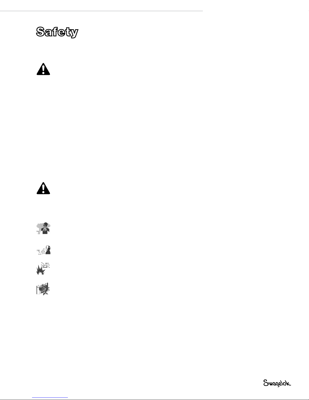
Safety alert symbol indicating a potential personal injury
hazard.
Safety alert symbol indicating a potential for personal
injury from electrical shock.
Safety alert symbol indicating a potential for personal
injury from exposure to fumes and gases.
Safety alert symbol indicating a potential for personal
injury from exposure to the weld arc.
Safety alert symbol indicating a potential for personal
injury resulting from a welding related re or explosion.
Safety alert symbol indicating a potential for personal
injury resulting from a welding related cylinder explosion.
Page 6

6 M200 Power Supply User’s Manual
WARNING
Orbital gas tungsten arc welding (GTAW) can be
hazardous. Only qualified persons should use this
equipment.
After welding, the work piece, weld head, electrode,
fixture block, and collets can be extremely hot and
may cause burns.
Keep children away.
Pacemaker wearers should consult with their
physician before operating this equipment.
Read and understand ANSI Standard Z49.1, “Safety
in Welding and Cutting,” from the American
Welding Society and OSHA Safety and Health
Standards, 29 CFR 1910 and 1926, from the U.S.
Government Printing Office.
The M200 power supply has no internal serviceable
parts and should not be disassembled. Return the
M200 power supply to an authorized Swagelok
sales and service representative for service.
ELECTRIC SHOCK can kill.
Touching live electrical parts and failure to operate
equipment properly can cause fatal electric shock
and severe burns. Incorrectly installed or improperly
grounded equipment is a hazard. To avoid injury:
■ Do not touch live electrical parts.
■ Keep all panels and covers securely in place. Do not
touch electrode connector, electrode, or rotor after
pressing start. The electrode is electrically charged
during the weld process.
■ Follow local electrical codes and the guidelines in
this manual when installing the M200 power supply.
Shock hazards can exist even when equipment is
properly installed, so it is important that the operator
be trained in the proper use of the equipment and
follow established safety practices.
■ Frequently inspect input power cord for damage or
bare wiring—replace immediately if damaged.
■ Properly unplug the power cord. Grasp the plug to
remove it from the receptacle.
Page 7

FUMES AND GASES can be hazardous.
Welding produces fumes and gases. Breathing these
fumes and gases may be hazardous to your health.
Build-up of gases can displace oxygen and cause injury
or death. To avoid injury:
■ Do not breathe fumes or gases.
■ Ventilate the area and/or use exhaust at the arc to
remove welding fumes and gases.
■ When welding materials that produce toxic fumes,
such as galvanized steel, lead, cadmium-plated
steel or other coated metals (unless the coating is
removed from the weld area), or any other welding
material, keep exposure below threshold limit
values (TLV), permissible exposure limits (PEL),
or other applicable health and safety limitation. If
necessary, wear a respirator. Read and understand
the Material Safety Data Sheets (MSDS) and
follow the manufacturer’s instructions for metals,
consumables, coatings, cleaners, degreasers, or
any other substance that may be present during the
weld process.
■ Do not work in a conned space unless it is well
ventilated or you are wearing an air-supplied
respirator. Always have a trained watch-person
nearby. Welding fumes and gases can displace air
and lower the oxygen level causing injury or death.
Be sure the breathing air is safe.
■ Do not weld in locations near degreasing, cleaning,
or spraying operations. The heat and rays of the
arc can react with vapors to form highly toxic and
irritating gases.
■ The ultraviolet light emitted by the welding arc
acts on the oxygen in the surrounding atmosphere
to produce ozone. Test results➀, based upon
present sampling methods, indicate the average
concentration of ozone generated in GTAW process
does not constitute a hazard under conditions of
good ventilation and welding practice.
■ Shut off gas supply when not in use.
M200 Power Supply User’s Manual 7
➀ Welding Handbook, Vol 2, 8th ed., American Welding Society.
Page 8
8 M200 Power Supply User’s Manual
ARC RAYS can burn eyes.
Arc rays from the welding process produce intense
visible and invisible (ultraviolet and infrared) rays that
can burn eyes. The M200 power supply is meant for
use only with enclosed Swagelok weld heads, which
minimize exposure to these harmful rays. To avoid
injury:
■ Do not look at welding arc.
■ Use protective screens or barriers to protect others
from ash and glare; warn others not to watch the
arc.
■ Wear personal protective equipment, including eye
protection.
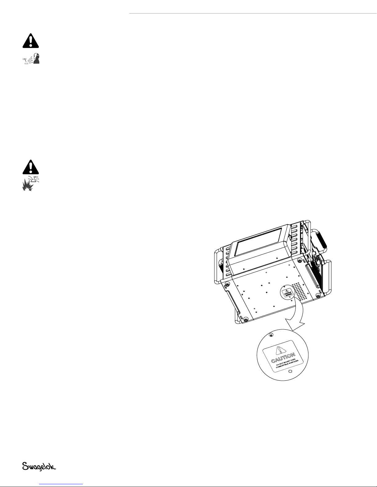
WELDING can cause fire or explosion.
Welding on closed containers, such as tanks, drums, or
pipes, can cause them to explode. The hot work piece
and hot equipment can cause res and burns. Ensure
the area is free of combustibles before welding. To
avoid injury:
■ Do not place the M200 power supply over a
combustible surface. See the label on the bottom of
the M200 power supply (Fig. 1).
■ Do not weld in a combustible environment.
■ Watch for re, and keep a re extinguisher nearby.
■ Do not weld on closed containers such as tanks,
drums, or pipes, unless they are properly prepared
in accordance with AWS F4.1.
■ Do not use the M200 power supply to thaw frozen
pipes.
■ Do not use extension cords that are in poor physical
condition or have insufcient current capacity.
Failure to do so can pose re and shock hazards.
■ Sparks and spatter are thrown from the weld arc.
The M200 power supply is meant for use with
enclosed weld heads, which minimizes exposure
to spatter. Wear proper protective equipment,
including eye protection.
Fig. 1— M200 Power Supply Mounting
Caution Label
Page 9

CYLINDERS may explode if damaged.
Gas cylinders used as part of the orbital GTAW process
contain gas under high pressure. If damaged, a cylinder
can explode. To avoid injury:
■ Protect compressed gas cylinders from excessive
heat, mechanical shocks, slag, open ames, sparks,
and arcs. Follow all site safety precautions and
protocol.
■ Install cylinders in an upright position by securing
to a stationary support or cylinder rack to prevent
falling or tipping.
■ Keep cylinders away from any welding or other
electrical circuits.
■ Never weld on a pressurized cylinder—explosion will
result.
■ Use only correct shielding gas cylinders, regulators,
hoses, and ttings designed for the specic
application; maintain them and associated parts in
good condition.
■ Keep head and face away from valve outlet when
opening cylinder valve.
■ Keep valve protective cap in place over valve except
when cylinder is in use or connected for use.
■ Read and follow instructions on compressed
gas cylinders, associated equipment, and CGA
publication P-1 listed in Referenced Documents,
page 11.
M200 Power Supply User’s Manual 9
Page 10
10 M200 Power Supply User’s Manual
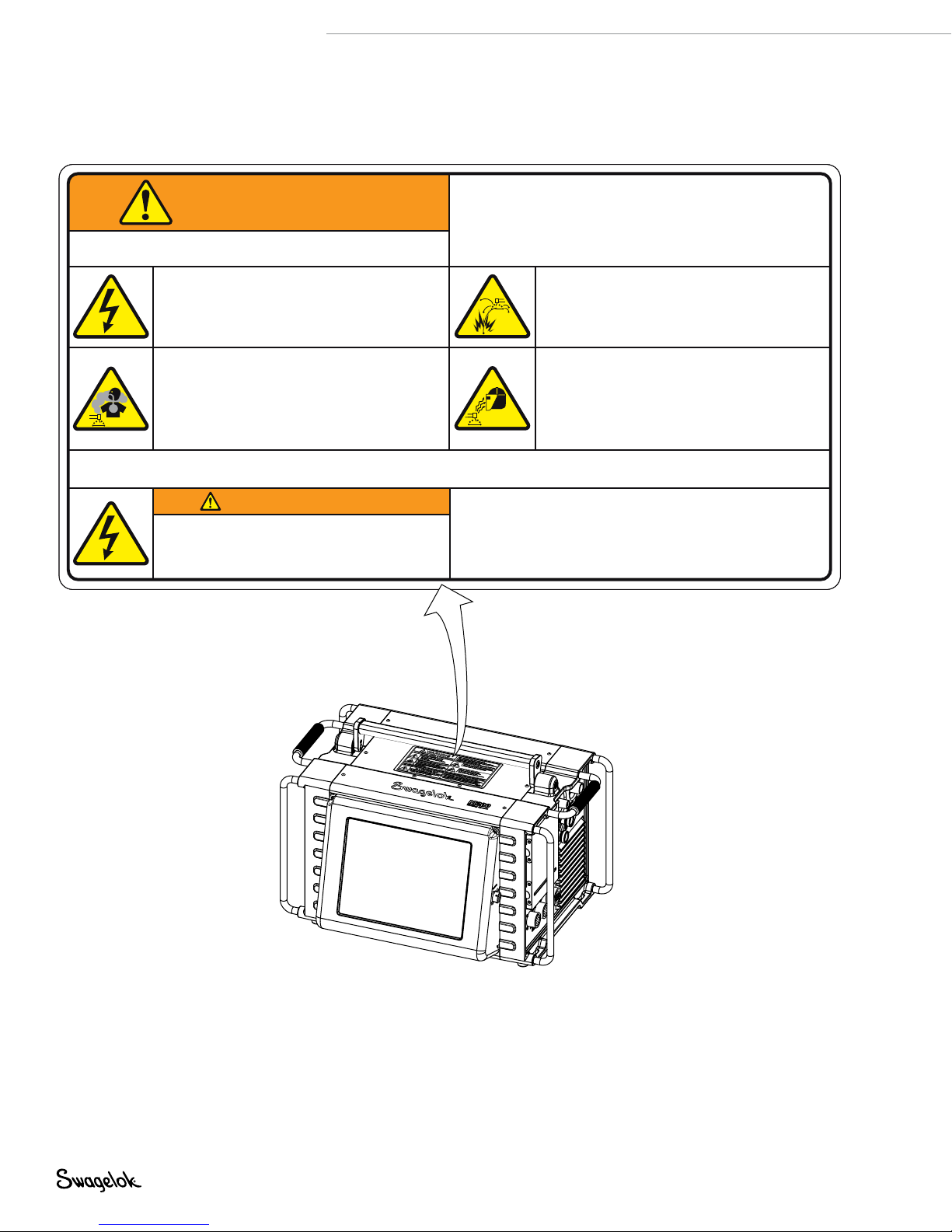
M200 Power Supply Warning Label
This warning label must remain afxed to the top of the power
supply (Fig. 2).
ARC WELDING can be hazardous.
• Read and follow this label and the User’s Manual.
WARNING
Do Not Remove, Destroy, or Cover This Label
For user information contact Swagelok Co. (www.Swagelok.com)
ELECTRIC SHOCK can kill.
• Do not touch live electrical parts.
• Electrode and rotor are live during
weld cycle.
• Keep all panels and covers securely in place.
FUMES AND GASES can be hazardous.
•
Do not breathe fumes or gases.
•
Use ventilation or exhaust to remove fumes
from breathing zone.
•
Read Material Safety Data Sheets (MSDS’s
and follow manufacturer’s instructions for
the material used.
Read American National Standard Z49.1, “Safety in Welding and Cutting,” from American Welding Society, 550 N.W. LeJeune Rd., Miami, FL 33126;
OSHA Safety and Health Standards, 29 CFR 1910 and 1926, from U.S. Government Printing Office, P.O. Box 371954, Pittsburgh, PA 15250
AVERTISSEMENT
UN CHOC ELECTRIQUE peut être mortel.
• Seules des personnes qualifiées peuvent
installer et utiliser cet appareil.
• Only qualified persons are to install and operate this unit.
• Keep children away.
• Pacemaker wearers keep away.
• Return to authorized sales and service center for service.
WELDING can cause fire or explosion.
• Do not weld on closed containers.
• Do not use in a combustible environment
or over a combustible surface.
ARC RAYS can burn eyes.
• Do not look at welding arc.
)
• Wear personal protective equipment
including eye and ear protection.
LE SOUDAGE A L’ARC peut être dangereux.
•
Lisez et respectez cette étiquette ainsi que le manuel utilisateur.
•
Ne pas utiliser dans un environment combustible ou au
dessus d'une surface combustible.
•
Ne touchez pas les parties électriques sous tension.
• L'électrode et le rotor sont sous tension pendant le soudage.
SWS-M200-LBL-WARN-E
Fig. 2—M200 Power Supply Warning Label
Page 11

Referenced Documents
1. AWS F4 .1, Recommended Safe Practices for the
Preparation for Welding and Cutting of Containers and
Piping.
American Welding Society, 550 N.W. LeJeune Rd, Miami, FL
33126 (www.aws.org).
2. ANSI Z49.1, Safety in Welding Cutting, and Allied
Processes.
American Welding Society, 550 N.W. LeJeune Rd, Miami, FL
33126 (www.aws.org).
3. CGA Publication P-1, Safe Handling of Compressed Gases
in Cylinders.
Compressed Gas Association, 4221 Walney Road, 5th Floor,
Chantilly VA 20151-2923, (www.cganet.com).
4. OSHA 29CFR 1910 Subpart Q, Welding Cutting, and
Brazing.
Acquire from U.S. Government Printing Ofce,
Superintendent of Documents, P.O. Box 371954, Pittsburgh,
PA 15250 (www.osha.gov).
5. OSHA 29CFR 1926 Subpart J, Welding and Cutting.
Acquire from U.S. Government Printing Ofce,
Superintendent of Documents, P.O. Box 371954, Pittsburgh,
PA 15250 (www.osha.gov).
M200 Power Supply User’s Manual 11
Page 12

12 M200 Power Supply User’s Manual
Page 13

M200 Power Supply User’s Manual 13
Installation and Setup
Page 14
14 M200 Power Supply User’s Manual
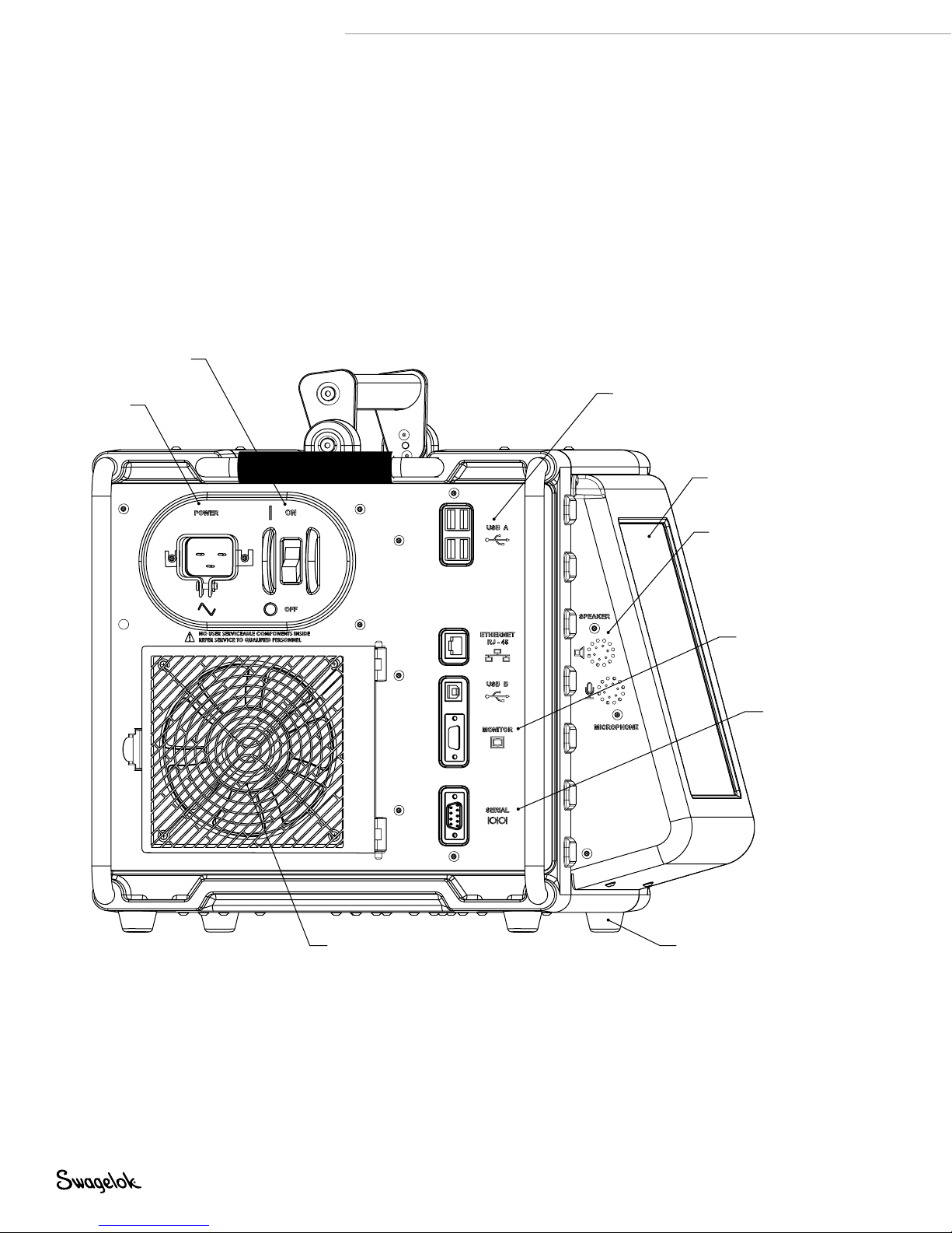
Description
The Swagelok Welding System M200 power supply
provides precise control of weld current, electrode
travel speed, and OD shield gas ow to produce
consistent and repeatable weld results.
The unit features a touch-screen display for easy
navigation and data input. To access menus and
input weld data, the operator presses the touch
screen over the selection. In the Single Level Mode,
users can enter data using simulated thumb wheels.
On/of f switch
Four USB A version 1.1 ports on the side of the M200
power supply accept compatible USB hardware,
such as a USB mouse or keyboard, with no additional
software required. A USB ash drive (not supplied)
provides portable memory and can be used to
transfer data to other M200 power supply units and/
or a PC. A 1 GB USB ash drive is recommended.
There are additional ports for video SVGA output and
a serial cable for direct PC connection.
Power cord
connection
4 USB A 1.1 ports
Touch screen
Speaker
Video (SVGA) out
connection
Serial output
connection
Fig. 3—M200 Power Supply Left Side
Fan housing
Nonslip feet
Page 15
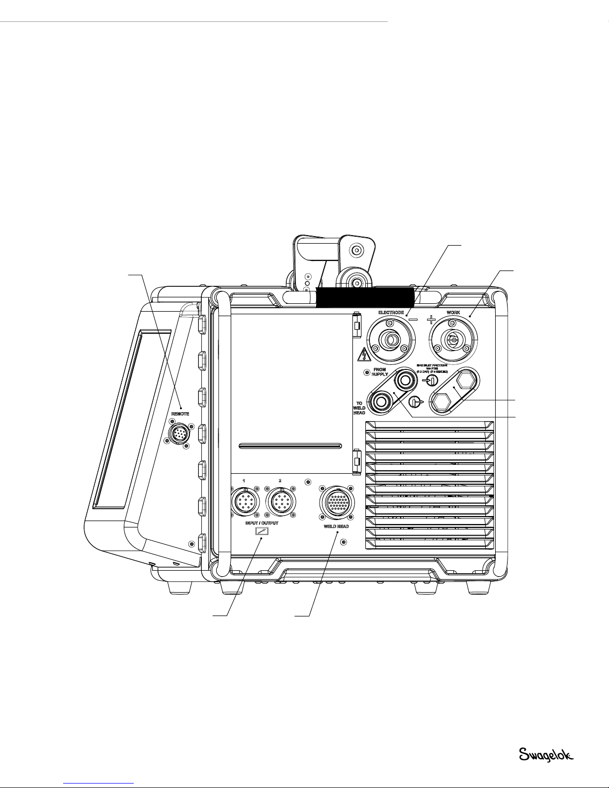
Remote
pendant
connection
M200 Power Supply User’s Manual 15
Electrode
connection (red)
Work
connection
(green)
Auxiliary output
connections
Printer housing
Weld head
connection
Fig. 4—M200 Power Supply Right Side
ID shield gas
connections
OD shield gas
connections
Page 16

16 M200 Power Supply User’s Manual
Unpacking the M200 Power Supply
Table 1—Shipping Case Contents
Description Ordering Number Qty
M200 power supply SWS-M200-XX-Y
- XX denotes power cord
plug type
- Y denotes user’s manual
language
Power cord CWS-CORD-X
- X denotes power cord
plug type
1/4 in. male
Quick-Connect stem
M200 Power Supply
User’s Manual
Warranty Information Form — 1
SS-QC4-S-400 1
MS-13-212-Y
- Y denotes user’s manual
language other than English
Remove the contents of the shipping case (Table 1):
1. Use the handle on the top of the M200 power supply to lift it
out of the case. Place the M200 power supply upright on a
stable surface.
2. Check the M200 power supply and accessories for damage.
3. Record the model number and serial number from the rating
label on the back of the M200 power supply (Fig. 5), along
with the delivery date, on the M200 Power Supply Warranty
Information form and the Registration Information form,
page 17. Return the Warranty Information form to your
authorized Swagelok representative to activate the warranty.
1
1
1
Note: Contact your authorized Swagelok
representative if the unit is damaged.
Note: Do not store the M200 power
supply near corrosive materials.
Store indoors and cover when not
in use.
Page 17

Registration Information
Your authorized Swagelok representative provides support and
service for your M200 power supply and Swagelok weld heads.
Please take a moment to ll out the information listed below.
See the rating label on the back of the M200 power supply.
(Fig. 5) for the model and serial numbers.
Keep this information available in case you need to contact your
authorized Swagelok representative.
Date of Delivery: _________________________________________
Power Supply Model Number: ____________________________
Serial Number: ____________________________
Weld Head Model Number: ____________________________
Serial Number: ____________________________
Weld Head Model Number: ____________________________
Serial Number: ____________________________
M200 Power Supply User’s Manual 17
Weld Head Model Number: ____________________________
Serial Number: ____________________________
Weld Head Model Number: ____________________________
Serial Number: ____________________________
Company Name: _________________________________________
Swagelok Distributorship: _________________________________
Fig. 5—M200 Power Supply Rating Label
Page 18

18 M200 Power Supply User’s Manual
Tools and Accessories Required
Table 2—Tools and Accessories
Tool/Accessory Included-
Hex wrenches (1/2 to 5/32 in.) Yes Weld head
Electrode package Yes
Arc gap gauge Yes
Flat-blade screw driver Yes Weld head
Centering gauge Yes
Calipers or micrometer No —
Purge kit
(Ordering number: SWS-PURGE-KIT)
Low-moisture gas lines No —
Gas source No —
Pressure regulator No —
ID purge gas flow meter No —
Pressure gauge No —
➀ The Series 40 weld head does not include an electrode, arc gap gauge, or
centering gauge package.
➀
➀
➀
No —
Provided
With
Weld head
Weld head
Fixture block
Electrical Requirements
M200 Power Supply Installation
All user-supplied wiring and related components must be installed
in accordance with local electrical codes. A dedicated electrical
circuit may be required to maintain optimum current levels. If
input voltage is 100 V or less, output power capabilities may be
reduced.
WARNING
The M200 power supply must
be grounded or electrical shock
can result.
Table 3—Voltage and Current Requirements
Power Supply Model Voltage Requirement Service Current
M200
100 V (ac) 20 A
230 V (ac) 16 A
See Specifications, page 100, for detailed power input and
output information.
Using Extension Cords
Extension cords may be used with the M200 power supply.
Extension cords must meet the current capacity specications
in Table 43, page 101.
Page 19
M200 Power Supply User’s Manual 19
Setting up the M200 Power Supply
1. Position the M200 power supply so that both sides are
accessible.
2. Make sure the power switch on the left side of the M200
power supply is in the off ( O ) position.
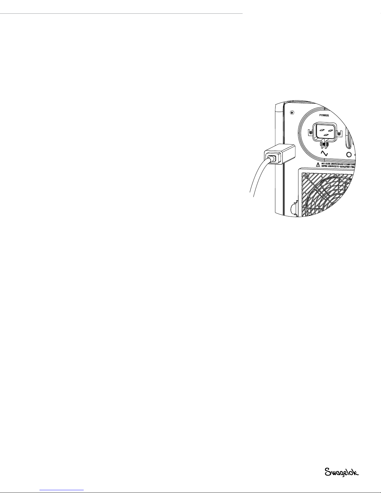
3. Connect the power cord to the power connector on the
side of the unit (Fig. 6). Turn the connector a quarter-turn
clockwise to lock it in place.
4. Optional: Install the fan lter on the left side of the M200
power supply. See page 51.
Note: The M200 power supply should not
be operated when resting on either
the left or the right side (printer or
fan/filter side) or when tilted more
than 15° on its horizontal axis. The
MFC will not function properly in
these positions.
Fig. 6—Connecting the Power Cord
Page 20
20 M200 Power Supply User’s Manual
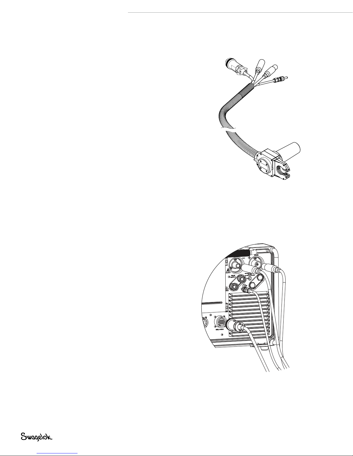
Installing the Weld Head
The weld head assembly attaches to the right side of the M200
power supply with four separate connectors (Fig. 7) :
■
Weld head quarter-turn connector
■
Electrode (red)
■
Work (green)
■
Weld head OD shield gas.
1. Align the notch on the weld head quarter-turn connector
with the small tab in the M200 power supply socket
labeled weld head (Fig. 8) and insert the connector. Turn
it clockwise to lock it in place. An audible click indicates
that the connection is locked. This connection provides the
control signals to drive the weld head.
Note: Use the weld head adapter cable, ordered separately,
if the weld head does not have a quarter-turn
connection. Attach the weld head adapter cable to
the end of the threaded multipin connector. Tighten
the weld head adapter cable until only two or three
threads are visible.
2. Insert the red connector arrow side up into the M200 power
supply red socket labeled electrode. Turn the connector
one-quarter turn clockwise to lock it in place. This
connection is the negative (–) terminal of the weld head.
3. Insert the green connector arrow side up into the M200
power supply green socket labeled work. Turn the
connector one-quarter turn clockwise to lock it in place.
This connection is the positive (+) terminal of the weld head.
4. Insert the weld head OD shield gas Swagelok quick-connect
stem into the M200 power supply tting labeled to weld
head. This connection provides shielding gas to the weld
head through the mass ow controller in the power supply.
Weld head
quarter-turn
connector
Fig. 7— Weld Head Assembly Connections
NOTICE
All connections must be fully seated
and locked in place to prevent damage
to connections or weld head.
Electrode (red)
Work (green)
Weld head
OD shield gas
Fig. 8— Connecting the Weld Head
Assembly to the Power Supply
WARNING
Do not remove the weld head
from the M200 power supply
while a weld is in process.
Electrical shock can result.
Page 21
Setting Up the Gas Supply System
The M200 power supply has an integral mass ow controller
(MFC) to control and monitor the ow of the gas supply system
that provides OD shield gas to the weld head. OD shield gas
lls the weld chamber to protect the electrode and weld puddle
from contaminating elements in the surrounding air.
ID purge gas ows within a tube or at the back of a weld joint to
remove oxygen and prevent oxidation.
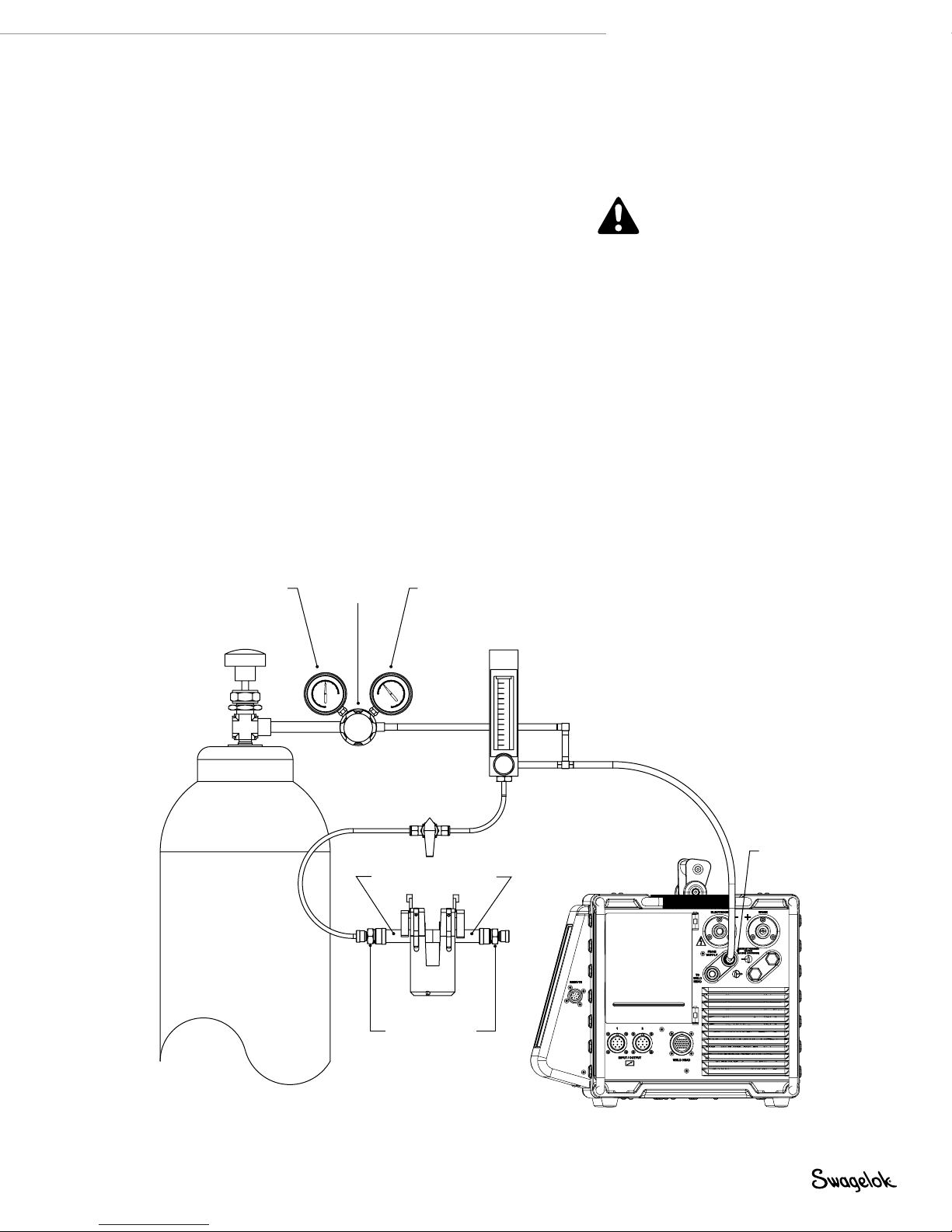
Typical OD Shield / ID Purge Gas Supply System
Figure 9 shows a typical gas supply system. Before setting up
the gas supply system, read and understand the Safety section
of this manual. See page 5.
1. Make sure the gas storage containers are upright and
secured before use.
2. Check all connections for leaks.
3. Use only Swagelok quick-connect stems (ordering number
SS-QC4-S-400) as gas connectors on the M200 power supply.
4. Regulate the OD shield gas pressure to obtain the desired
ow rate. The typical pressure range is 45 to 50 psig (3.1 to
3.4 bar). Flow rates greater than 70 std ft3/h (33 std L/min)
may require higher pressures.
M200 Power Supply User’s Manual 21
CAUTION
Do not mix or interchange
parts with those of other
manufacturers. Personal injury
or equipment damage can result.
NOTICE
Do not exceed an inlet pressure of
100 psig (6.8 bar) or MFC can be
damaged.
NOTICE
The MFC is not a shutoff device. There
may be gas flow of up to 1/2 std ft
(0.24 std L/min) when the shield gas is
off.
3
/h
High-pressure
gauge
(0 to 3000 psig
[206 bar])
Inert gas cylinder
Two-stage
regulator
Tubing to be welded
(Swagelok union or reducing
union with nylon ferrules or
ultra-torr fitting. See Table 2
for purge kit ordering
Low-pressure
gauge
(0 to 100 psig
[6.8 bar])
ID purge gas
shutoff valve
Fixture block
Purge fittings
nu mber.)
Flow meter for
ID purge gas
Supply manifold
M200
power supply
OD shield gas
supply inlet
Fig. 9—Typical Gas Supply System
Page 22

22 M200 Power Supply User’s Manual
Powering On the M200 Power Supply
for the First Time
1. Connect the power cord to a properly rated and grounded
electrical receptacle.
2. Power on the M200 power supply by toggling the on/off
switch on the left side of the unit to the on ( I ) position. The
Swagelok screen will appear.
3. The Setup Wizard (Fig. 10) will prompt the user to select a
user language.
4. The Swagelok Embedded System End User License
Agreement (page 122) will appear. You must accept the
terms of this agreement to continue the Setup Wizard and
use the M200 power supply.
5. Set the owner password. If desired, set security or
programmer passwords. See Passwords, page 46, for
more information.
6. The Main Menu will appear.
Note: The fan will turn on automatically. Press the Fan
button to turn the fan off.
CAUTION
The rotor will move when the
M200 power supply is powered
on. The rotor is a potential
pinch point.
Fig. 10—Language Setup Wizard
Powering Off the M200 Power Supply
To power off the M200 power supply, toggle the on/off switch
on the left side of the power supply to the off ( O ) p osition.
Note: Do not power off the M200 power supply when
updating software.
Restarting the M200 Power Supply
1. Power on the M200 power supply by toggling the on/off
switch on the left side of the unit to the on ( I ) position.
2. The Swagelok screen (Fig. 11) will appear.
3. Enter the security or programmer password if one has been
set.
4. The Main Menu will appear.
Note: The owner password is the master
key to the M200 power supply. If
it is lost or forgotten, contact your
authorized Swagelok representative.
After ownership of the unit is
verified, you will receive a temporary
password to allow access to the unit.
Fig. 11—Swagelok Screen
Note: The MFC requires 5 minutes to
warm up to ensure accurate gas flow
control if the M200 power supply is
not at operating temperature.
Page 23
M200 Power Supply User’s Manual 23
Using the Touch Screen
The touch screen of the M200 power supply is the built-in
method for navigating functions and entering data.
The touch screen responds to ngertip operation and was
designed to accommodate gloves. The touch screen may be
difcult to use if it is dirty or has water droplets on its face.
Keep the touch screen clean and dry.
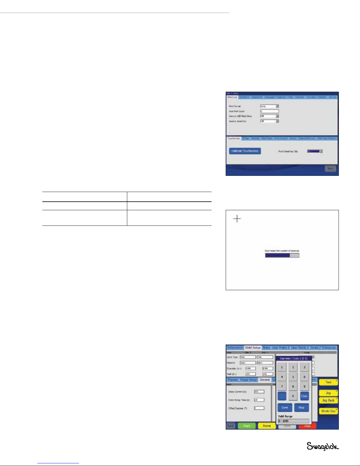
If the touch screen does not respond as expected, it may
need to be calibrated. From the Main Menu, select Setup >
Touchscreen > Calibrate Touchscreen (Fig. 12). A series of
cross hair targets will appear onscreen. While in the position
(seated or standing) you normally use the M200 power supply,
touch each target (Fig. 13) as it appears. When no more targets
appear, the M200 power supply is calibrated.
User Interface
The user interface of the M200 power supply was designed for
easy navigation.
The “path” at the top of each screen (except the Weld screens)
indicates your location:
Path Location
Main > Setup Setup mode
Main > Program > Auto Create Auto Create function
in the Program mode
Note: Do not expose the M200 power
supply to water or visible moisture.
The touch screen can be cleaned
with glass cleaner and a clean cloth.
To prevent accidental operation,
power off the M200 power supply
before cleaning.
Fig. 12—Calibrate Touchscreen Button
To select a function or mode, press the onscreen button or
tab with your nger. To enter information, press the eld to be
lled in. Depending on the information to be entered, a numeric
keypad, alphanumeric keyboard, or drop-down menu will appear.
A USB mouse and keyboard also can be connected to the M200
power supply for data entry.
Numeric Keypad
The valid range for the selected parameter will display at the
bottom of the keypad.
■
Press the number keys (Fig. 14) to enter information. Press
Done to save the settings and close the keypad.
■
Press <- Bksp to erase the last character entered. Press
Clear to erase the entire entry.
Fig. 13—Calibration Target Screen
Fig. 14— Numeric Keypad
Page 24
24 M200 Power Supply User’s Manual
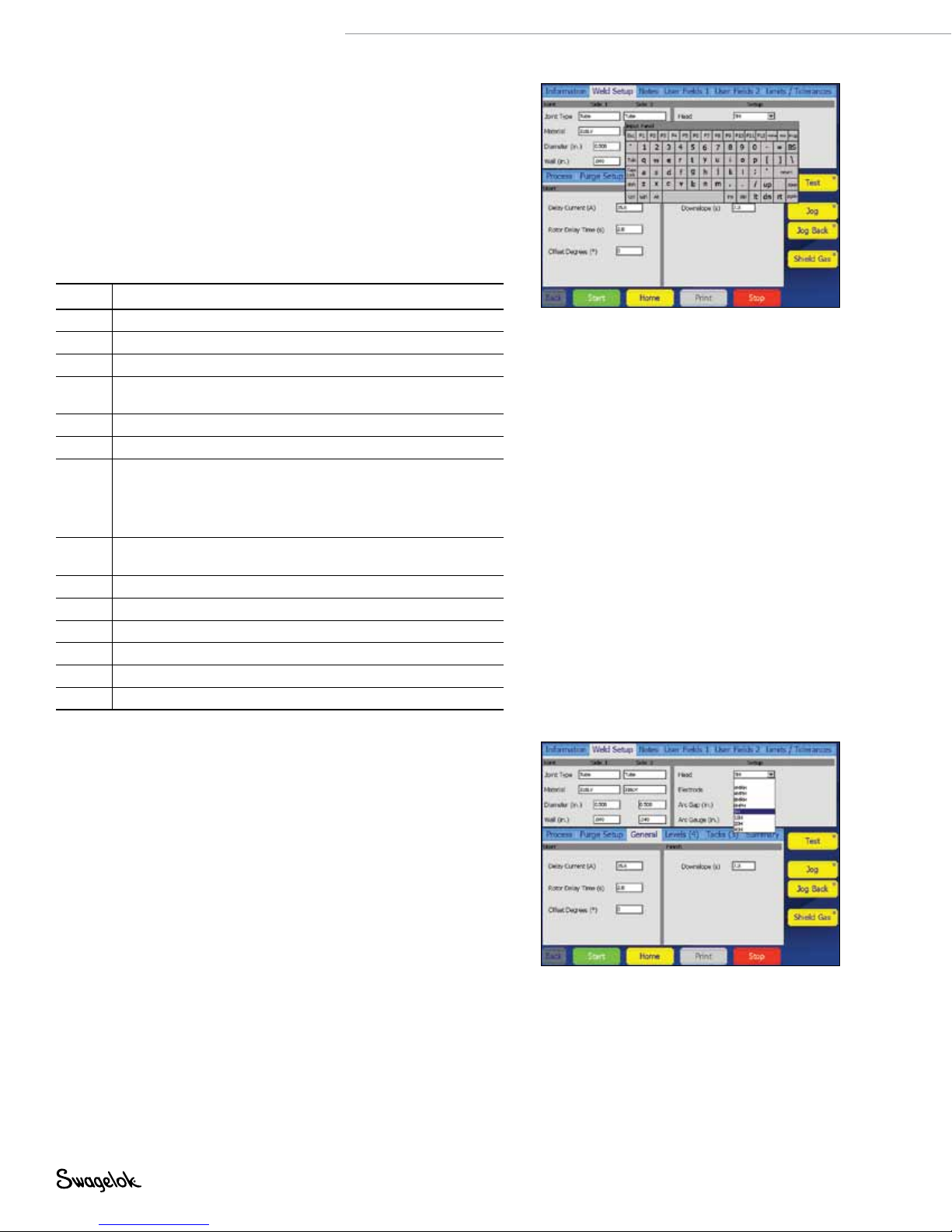
Keyboard
■
Use the onscreen keyboard (Fig. 15) as you would a
computer keyboard.
■
To reposition the keyboard, press the gray bar at the top of
keyboard and drag it to the new position.
■
To close the keyboard, press return.
Note: The return key will not start a new line of text.
Table 4—Key Functions
Key Function
Home Moves cursor to the beginning of the line.
End Moves cursor to the end of the line.
Prop Moves cursor to the end of the line.
BS Backspace. Deletes character to the left of the cursor.
Tab Closes the keyboard.
return Closes the keyboard.
Ctrl Ctrl + z: Undo last step.
del Deletes character to right of cursor.
lt Moves cursor one space to the left.
rt Moves cursor one space to the right.
up Moves cursor to line above.
dn Moves cursor to line below.
pgup Moves to the preceding page.
pgdn Moves to the next page.
Also deletes selections that have been highlighted.
Ctrl + x: Cut and save selected/highlighted text.
Ctrl + c: Copy and save elected/highlighted text.
Ctrl + v: Paste saved text at cursor point.
Also deletes selections that have been highlighted.
Fig. 15— Onscreen Keyboard
Note: To select text, highlight it by pressing
and dragging your finger over the
selection.
Drop-Down Menus
Drop-down menus (Fig. 16) allow you to select entries from
a list. Drop-down menus are indicated by a down arrow (▼).
Press the eld or arrow to display the list of selections. Highlight
the selection to change the value.
Fig. 16—Drop-Down Menu
Page 25

Operation
This section describes the basic operation of the M200 power
supply.
Main Menu
The Main Menu (Fig. 17 ) provides access to the M200 power
supply’s functions. Select functions by pressing the onscreen
button or by using a USB mouse to click on the selection. The
Main Menu buttons are described in Table.
M200 Power Supply User’s Manual 25
Fig. 17—Main Menu
Page 26

26 M200 Power Supply User’s Manual
Table 5—Main Menu Selections and Functions
Weld
File
Program
Weld Log
Setup
Next Home
The Weld screens display detailed information
about the weld and are used to input parameters,
start the weld, and monitor the weld process.
The information displayed on the Weld screens is
saved with the weld procedure.
See page 28 for more information about the
Weld screens.
The File screens are used to print, preview, delete,
load, and save weld procedures. The File mode
applies only to weld procedures and does not affect
the M200 power supply Setup or Weld Log files.
See page 35 for more information about the File
screens.
The Program screens are used to create new weld
procedures using Auto Create or Manual Create.
See page 38 for more information about the
Program screens.
The Weld Log screens are similar to the File
screens but are exclusively for Weld Log records.
Weld Log records may be viewed, printed, copied,
or deleted using these screens. Weld Log records
may be saved to a USB flash drive for transfer to
a PC. Weld Log records may also be exported to a
PC using a serial cable.
See page 39 for more information about the
Weld Log screens.
The Setup screens are used to change options,
set dimensional units and passwords, and review
settings. Changes are saved in the M200 power
supply’s internal memory and are not part of a weld
procedure.
The Setup mode also contains utilities for updating
software, resetting weld counts, and monitoring
free memory.
See page 42 for more information about the
Setup screens.
When a Swagelok weld head is first connected
to the M200 power supply, the power supply
assumes the rotor is at true home. If it is not,
press Next Home to move the rotor to the next
of several “home” positions. The weld head
model determines the number of home positions.
Continue pressing Next Home until the rotor
reaches true home (Fig. 18.)
If the weld head cannot find true home, see
Troubleshooting, page 109.
Note: In any M200 power supply screen
or menu, press Back to return to
the previous screen. Press Refresh
to reload and update the current
screen.
CAUTION
The rotor will move when Next
Home is pressed. The rotor is a
potential pinch point.
True home
(fully open)
Not true home
Fig. 18—Rotor Home Position
Page 27
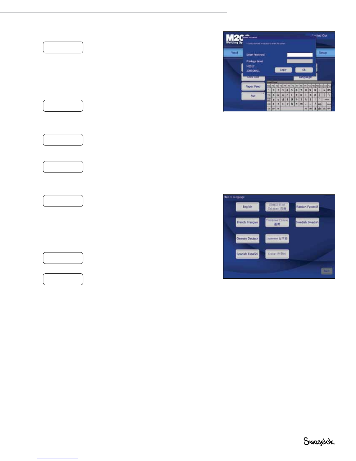
Table 5—Main Menu Selections and Functions
M200 Power Supply User’s Manual 27
Lock Out
(Fig. 19)
Paper Feed
Fan
Single Level
Mode
Language
(Fig. 20)
Help
About
Pressing Lock Out will lock the M200 power
supply. Once the M200 power supply is locked
out, pressing any button on the screen will
cause a password prompt to appear. The owner,
programmer, or security password must be entered.
Note: This feature is not available unless a
programmer or security password has been
set in Setup.
See Passwords, page 46, for more information.
The printer is located on the right side of the M200
power supply, above the weld head connection.
Paper Feed advances the paper through the printer.
See page 45 for information on changing the
paper feed length.
The fan is normally in the Fan Power-On State and
will turn on as needed to cool the M200 power
supply. To turn the fan on manually, press Fan. The
fan will run continuously until Fan is pressed again.
Single Level Mode is for users who prefer
the Swagelok D75 and D100 power supply
programming format.
See Single Level Mode Operation, page 84, for
more information.
The Language screen allows you to change the
language shown on the M200 power supply’s
screens.
Press the Language button to select the new
language. As soon as the language is selected,
the Back button at the bottom of the screen will
display that language. Press the Back button to
return to the Main Menu, and the screen will be in
the selected language.
Displays the user’s manual. The user manual will
display in the language selected if available. The
English version will display if it is not available.
Displays copyright and patent information.
Fig. 19— Password Prompt Screen
Note: Changing the Fan Power-On State
to off on the Setup > Operation tab
will prevent the fan from turning on
automatically when the M200 power
supply is powered on.
Fig. 20—Language Screen
Page 28
28 M200 Power Supply User’s Manual
Weld Screens
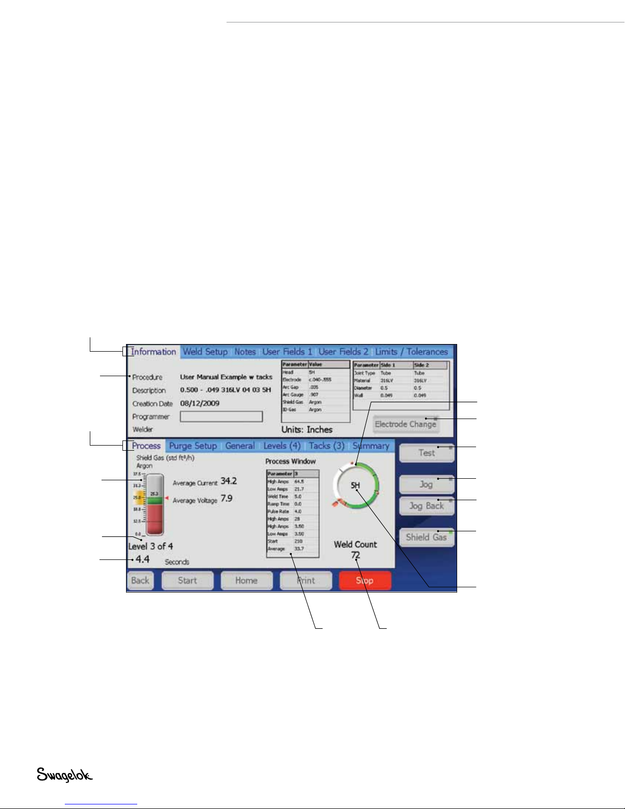
The Weld screens (Fig. 21) are used to view and adjust (see
Note) the parameters of the active weld procedure. The screen
is divided into upper and lower sections.
The Upper Section Tabs contain information related to the weld
procedure and options: user elds, limits / tolerances, etc.
The Lower Section Tabs are elds that make up the basic
parameters of a weld: purge settings, levels, tacks, and general
settings.
Upper
section
tabs
Note: Changing the weld procedure
parameters will add “(modified)” to
the weld procedure name on the
screen and cause the name to turn
red in color. The weld procedure
must be saved to make the changes
a permanent part of the procedure.
See Table 9, page 35.
Weld
procedure
name
Lower
section
tabs
OD shield
gas visual
gauge
Status indicator
Time-
remaining
counter
Weld
procedure
parameters
Fig. 21—Weld Screens
Electrode position
Used to change
electrode
Test the active
procedure (no
current applied)
Jogs electrode
clockwise
Jogs electrode
counterclockwise
Turns on OD
shield gas
Weld head
installed
Weld count
Page 29
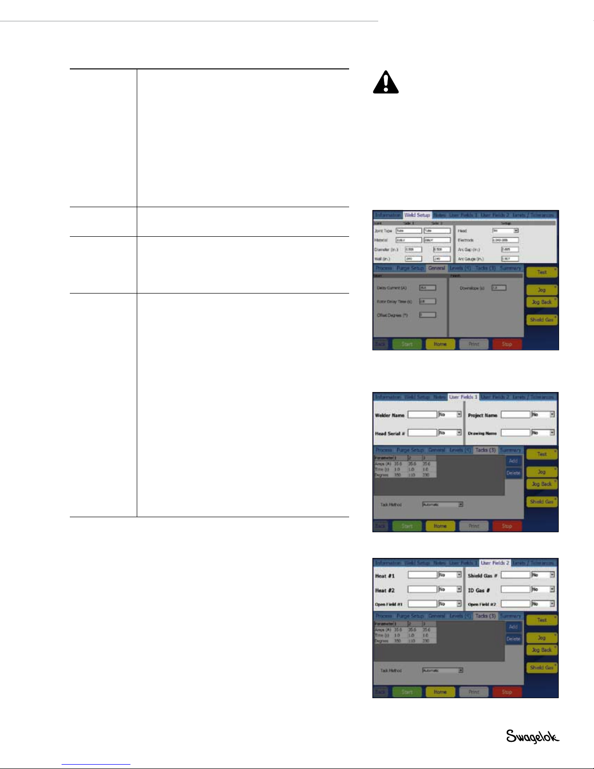
Table 6—Weld Upper Section Tabs
M200 Power Supply User’s Manual 29
Information
(Fig. 21)
Weld Setup
(Fig. 22)
Notes Displays an open field for entering comments and
User Fields 1
User Fields 2
(Fig. 23,
Fig. 24)
Displays a summary of weld setup parameters as
well as ID purge and OD shield gas types for the
active weld procedure. The eight most recent entries
for the Programmer field will display in a drop-down
box.
The Information tab also displays the Electrode
Change button, which positions the rotor for
electrode replacement and prevents the M200 power
supply from welding.
See the weld head user’s manual for instructions on
electrode replacement. After replacing the electrode,
press Electrode Change again. The rotor will move
back to the home position.
Displays the Joint and Setup fields and allows
adjustment of values.
observations. Press the white area once to display
the onscreen keyboard. Notes will be saved with
the weld procedure and shown in the Weld Log as
Procedure Notes.
Displays User Fields 1 and 2.
The software will remember the eight most
recent entries for each field and display them in a
drop-down box.
The owner or programmer can set data entry
requirements that must be completed before a weld
is performed. This information is part of the weld
procedure and is stored in the Weld Log.
Three options are available in drop-down boxes next
to each user field:
No An entry is not required for this field. It may
be entered at the discretion of the user.
Yes An entry is required for the field. The
entry will remain in that field until a new
weld procedure is loaded. Failure to enter
information into this field will cause a
disable code.
Change An entry is required in the field and must
be reentered with every weld. Failure to
enter information into this field will cause
a disable code.
CAUTION
The rotor will move when
Electrode Change is pressed.
The rotor is a potential pinch
point.
Note: Electrode Change disables most
other M200 power supply buttons.
Fig. 22—Weld Setup Tab
Fig. 23—User Fields 1 Tab
Fig. 24—User Fields 2 Tab
Page 30
30 M200 Power Supply User’s Manual
Table 6—Weld Upper Section Tabs
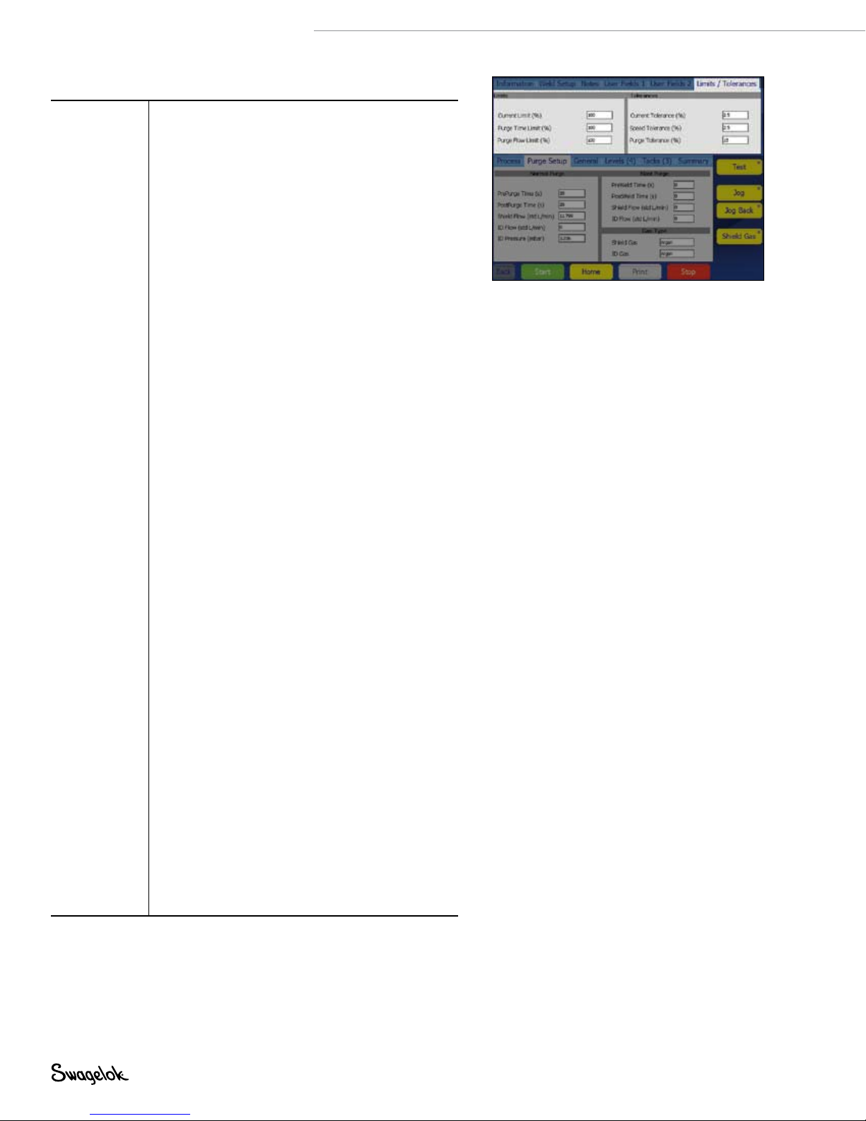
Limits /
Tolerances
(Fig. 25)
Limits
Limits are used to restrict the amount of adjustment
a user with a security password can make without
entering a programmer or owner password.
Limits from 0 to 100 % are set at the programmer
and owner levels. Current and Purge Limits are
represented as a percentage of the weld procedure
values.
Example: if the Average Amps for Level 1 is
100 A and the current limit is 50 %, the M200
power supply will not allow an adjustment of
Average Amps above 150 A or below 50 A. The
factory default for limits is 100 %.
Average Amps can be adjusted within the limits on
the lower section Levels tab using the up and down
buttons.
See Adjusting Average Amps, page 31, for more
information.
Purge parameters can be adjusted within the limits
on the Purge Setup tab.
Tolerances
The Weld Log records out-of-range values for
Average Amps, Average Speed, and OD Shield Flow
in the Weld Log, based on tolerances set. Tolerances
are adjustable at the programmer and owner levels,
as a percentage of the base value.
■
Current and speed tolerances are adjustable
up to 9.9 %. The factory default for new weld
procedures is 2.5 %.
■
Purge tolerance is adjustable up to 100 %. The
factory default is 15 %.
Example: if the Average Amps for Level 1 is
100 A and the current tolerance is 5 %, the M200
power supply will return a current tolerance error
at the end of the weld if the Average Amps is
below 95 A or exceeds 105 A.
Current tolerance. If the Average Amps tolerance is
exceeded during the weld, a current tolerance error
will be recorded.
Speed tolerance. If the average speed is outside of
the average speed tolerance at the end of the weld,
a speed tolerance error will be recorded.
Purge tolerance. Purge tolerance is represented
by the yellow band in the shield gas flow meter
displayed on the process tab. If the OD shield flow
is outside of the tolerance, the shield gas bar flow
meter display will turn red. If there is no OD shield
gas present during prepurge, the M200 power
supply will not proceed. If the OD shield gas flow
drops below 8 std ft
3
/h (3.8 std L/min) during a weld,
the M200 power supply will stop welding to prevent
possible damage to the weld head.
See page 106, Weld Errors.
Fig. 25— Limits / Tolerances Tab
Page 31

Table 7—Weld Lower Section Tabs
M200 Power Supply User’s Manual 31
Process
(Fig. 26)
Purge Setup
(Fig. 27)
General
(Fig. 28)
Levels (X)
(Fig. 29)
Displays the status and progress of the weld,
including tacks, error messages and electrode
position.
Displays the Normal Purge, Blast Purge, and Gas
Type fields.
Displays the Start and Finish fields.
A level is a section of the weld procedure defined by
the parameters shown in Fig. 29. Parameters can be
varied by level.
A weld procedure can have from 1 to 99 levels. The
number in parentheses indicates the number of
levels specified in that weld procedure.
Levels are shown in the process window in real time
during the weld. To add a level, press the top of a
column to highlight it, then press the Add button
on the right side of the window. A new column
containing a copy of the selected column’s data
will be added after the selected column. Repeat for
additional levels.
To delete one or more levels, press the top of the
column or columns to select them. Press the Delete
button on the right side of the window.
Adjusting Average Amps
Adjust Up / Down allows a user with a security
password to make Average Amps adjustments
within the limits and tolerances set by the owner or
programmer.
Select the level or levels to be adjusted and press
the up or down buttons to adjust Average Amps
(page 30) within the limits in a weld procedure
defined by the programmer. If no level is selected, all
levels are affected by Adjust Up / Down.
Average Amps is reduced with the down button or
increased with the up button.
■
The rst three presses of the up or down button
increase or decrease High Amps Width in
increments of 10 %, up to 30 %.
■
The next three presses of the up or down button
increase or decrease High Amps in increments
of 10 %, up to 30 %.
■
The nal three presses of the up or down button
increase or decrease Low Amps in increments of
10 %, up to 30 %.
To return to the original values for the weld
procedure you must reload the program from
memory.
See Limits / Tolerances, page 30, for more
information.
Fig. 26—Process Tab
Fig. 27—Purge Setup Tab
Fig. 28—General Setup Tab
Fig. 29—Levels Tab
Page 32

32 M200 Power Supply User’s Manual
Table 7—Weld Lower Section Tabs
Tacks (X)
(Fig. 30)
The M200 power supply supports weld procedures
with tacks—nonpenetrating spot welds used to hold
work pieces in place. The number in parentheses
indicates the number of tacks specified for the weld
procedure.
To set the tack method, choose from the options
available in the drop-down box next to the user field:
Automatic The entire selected weld procedure
will be completed when the Start
button is pressed on the Process
tab.
Tacks Only Only the tacks portion of the
selected weld procedure will be
completed. When the user returns
to the Process tab, a Start Tacks
button will appear under the Weld
Head Installed graphic. Press this
button to complete the tacks.
The Start button will change to
Start Levels. Press this button to
begin the remainder of the weld
procedure.
To add tacks, press the top of a column to highlight
it, then press the Add button on the right side of
the window. A new column containing a copy of
the selected column’s data will be added after the
selected column. Repeat for additional tacks.
To delete tacks, press the top of the column or
columns to select them, then press the Delete button
on the right side of the window.
Use the onscreen keypad to enter or change a
parameter.
See page 65 for more information about weld
procedures using tacks.
Fig. 30—Tacks Tab
Note: Tacks should be offset at least 10°
from the location of the arc start
of the levels to prevent arc wander
at arc start. The weld head returns
to the true home position after the
tacking section of a weld procedure.
Summary
(Fig. 31)
This tab provides information on the M200 power
supply’s Disable, Operational, and Error conditions
when a weld procedure is loaded.
The View button allows a look at the last completed
weld in the Weld Log.
The Clear Errors button remove all nonactive errors
from the Summary View (but not the Weld Log.)
Choose the Active Only check box to limit the
Summary View to the active weld.
Weld Log notes will print with the Weld Log.
Fig. 31—Summary Tab
Page 33

Table 8—Weld Screen Buttons
Test
Jog
Jog Back
Shield Gas
Start
Home
Print
Check or demonstrate a weld procedure with
this mode. Press to put the power supply in an
alternate operating mode that will not supply
current to the electrode. Press again to stop. The
current and voltage displays will not operate and
the weld counter will not advance. The light in
the corner of the button will blink while the power
supply is in Test mode.
Press to move rotor clockwise. Press again to stop.
The light in the corner of the button will blink while
the rotor is moving.
Press to move rotor counterclockwise. Press again
to stop. The light in the corner of the button will
blink while the rotor is moving.
Activates the mass flow controller and starts the
flow of OD shield gas to the weld head. Shield
gas will flow to the weld head until you press the
button again. Pressing the Shield Gas button does
not override Purge Setup settings in the weld
procedure, but gas will continue to flow after the
weld procedure is complete.
Starts the weld process.
See Performing a Weld, page 34.
Press to return the rotor to its true home position.
The rotor will move at maximum speed when
traveling to the home position, regardless of the
programmed rotor speed.
Prints last completed Weld Log record.
M200 Power Supply User’s Manual 33
Stop
Aborts the weld and halts the rotor if pressed
during the weld process. Stop also turns off OD
shield gas flow.
Page 34

34 M200 Power Supply User’s Manual
Performing a Weld
Read and understand all safety information contained in
this manual before starting the weld.
1. Complete all side panel connections as described in Setting
Up the M200 Power Supply, page 19, Installing the
Weld Head, page 20, and Setting Up the Gas Supply
System, page 21.
2. Install the electrode and set the arc gap using the arc gap
gauge in accordance with the weld head user’s manual.
3. Install the collets in the xture block.
4. Align and clamp the work pieces in the xture block.
5. Load an existing weld procedure as described in Load /
Save / Print / Delete Tab, page 35, or create a new weld
procedure as described in Program, page 38.
6. Connect the ID purge gas line to the work pieces to be
welded and set the ow meter.
7. Connect the weld head to the xture block.
8. Press the Start button.
WARNING
Do not touch the cable
connectors during the weld. If
the cables have been damaged,
the potential for an electrical
shock exists.
Display Indications During Welding
During welding, the status messages are displayed on the
Process tab, along with a time-remaining counter.
After the Weld is Complete
1. The M200 power supply will return to the “Ready” state.
2. Check the xture block to conrm that it has cooled before
handling. Increasing the postpurge or blast purge postweld
time will aid cooling.
3. Remove the weld head from the xture block. If it is difcult
to remove, release one of the side plate levers.
4. Remove the ID purge gas lines from the welded assembly.
5. Remove the welded assembly.
Weld Status Conditions
See Troubleshooting, page 102, for a list of disable,
operational, and weld error conditions.
CAUTION
Use gloves or other protective
devices if you must handle parts
immediately after welding. The
parts can be extremely hot and
may cause burns.
NOTICE
Do not immerse the hot fixture block in
water after welding. Allow the fixture
block to cool before performing the
next weld.
Note: Inspect the electrode after each
weld. Look for oxidation, wear, or
weld material on the tip.
Page 35

File Screens
The File screens are used to load, save, print, copy, delete, and
view weld procedures.
The Main > File screen has two tabs:
■
Load / Save / Print / Delete
■
File Copy
When the File screen opens, the M200 power supply searches
the internal memory and a connected USB ash drive. A large
number of folders can slow the search process. To reduce the
time required, delete unnecessary les or folders in the internal
memory and on the USB ash drive.
Load / Save / Print / Delete Tab
The File screen opens in the Load / Save / Print / Delete tab,
showing Folder and File Views in separate panes (Fig. 32):
■
The Folder View displays folders for the internal memory
and a connected USB ash drive.
■
The File View displays the weld procedures contained in an
open folder. The active weld procedure will have a green
icon.
In the Folder View, press the folder name or icon to open it.
The weld procedures will be displayed in the File View pane
in alphabetical order. The Folder View will also display any
subfolders contained in the original folder.
The buttons on the lower left (Print, View, Delete, and Load)
require you to select a le or folder before you press a button.
Press a weld procedure in the File View pane to highlight it. The
weld procedure name will appear in the File Name box below
the File View pane.
Enter a le name in the File Name box before pressing the Save,
Rename, or Create Folder buttons on the lower right of the
screen.
When a le name is entered and saved, a description that
includes the OD, wall thickness, tubing material, number of
levels, number of tacks, and weld head model will be added
automatically to the le name and displayed in the File View,
and whenever the weld procedure is loaded:
User’s manual example [0.500 - 0.049 316LV 04 03 5H A]
User’s manual example programmer-selected le name
0.500 OD of work piece
0.049 wall thickness of work piece
316LV tubing material
04 number of levels
03 number of tacks
5H weld head model needed for
weld procedure
A ATW weld procedure
P pipe schedule
S step program
The display will automatically change to the Weld/Process tab
after a Save has been performed.
M200 Power Supply User’s Manual 35
Selected file (with green icon)
Folder View pane File View pane
File Name boxStatus line
Fig. 32—Load / Save / Print / Delete Tab
Note: File names are limited to
alphanumeric characters. The M200
power supply software does not
support symbols such as:
, + , – , % , / , ” , ’ , , , or
similar characters.
Page 36

36 M200 Power Supply User’s Manual
Table 9—Load / Save / Print / Delete Tab Buttons
Print
Select the weld procedure in the File View pane
and press Print.
View
Delete
Load
Save
Rename
Create
Folder
Select the weld procedure from the File View
pane and press View. The file preview window
will appear showing the weld procedure name, a
description, the programmer’s name, and the date
the weld procedure was saved. Joint, Level, and
Tack parameters will also be displayed.
Press OK to return to the File screen.
Select the weld procedure or folder and press
Delete. A dialog box will open asking you to
confirm the delete. Press Yes to delete the weld
procedure or folder.
Select the weld procedure from the File View pane
and press Load. A message in the Status line will
confirm that the weld procedure was successfully
loaded.
Select the folder in which to save the weld
procedure. Press the File Name box. The keyboard
will appear. Enter the name of the new weld
procedure and press Save. The weld procedure will
be saved and displayed in the File View pane.
To rename a weld procedure, select the weld
procedure. The weld procedure name will be
shown in the File Name box. Press Rename and an
input box and a keyboard will be displayed. Enter a
new file name and press Rename in the input box.
Create Folder allows you to create an empty
subfolder in internal memory or on the USB flash
drive.
To create a new subfolder, highlight the folder you
want to put the new subfolder in and select the File
Name box. Enter the name of the new folder using
the keyboard and press Create Folder.
The new subfolder will appear in the Folder View
pane.
Note: Folders cannot be renamed using
Rename.
Page 37

M200 Power Supply User’s Manual 37
File Copy Tab
The File Copy tab (Fig. 33) allows the user to copy folders and
les between folders in internal memory or to and from a USB
ash drive.
When the File Copy tab opens, the internal memory and USB
Flash Drive (if attached) folders will be shown in both folder
panes. Press a folder twice to display its contents. Press twice
again to close it.
To copy a le, select the destination folder and the le to copy.
Press Copy >> or << Copy. If you select a folder, the entire
folder will be copied.
The Folder Move elds show the name of the folder or le
selected. The Status line at the bottom of the screen displays
status and error messages.
Table 10—File Copy Tab Buttons
Copy >>
<< Copy
Copies the selected folder or file from the left
Folder Move field to the selected destination in the
right Folder Move field.
Copies the selected folder or file from the right
Folder Move field to the selected destination in the
left Folder Move field.
Folder panes
Folder Move fields
Status line
Fig. 33—File Copy Tab
Page 38

38 M200 Power Supply User’s Manual
Program Screens
The Program screens (Fig. 34) are used to create new weld
procedures using Auto Create or Manual Create.
Table 11—Program Screen Buttons
Auto Create
(Fig. 35)
Manual
Create
(Fig. 36)
When you select Auto Create, a dialog box will
ask you to confirm overwriting the active weld
procedure. Press Yes to overwrite the active weld
procedure.
The active fields on the Auto Create screen are
shown in black. As these fields are completed, the
inactive fields (in gray) will activate in response to
the entries.
The eight most recent entries for the Programmer
field will display in a drop-down box.
To change the # Levels and # Tacks entries from
the default, press the field to display the keypad.
Enter your changes and press Done.
The Save Procedure drop-down box has two
options:
■
Active (No - Save) will take you directly to the
Main > Weld screen for immediate use. You
can run the weld procedure and make changes
before saving.
■
Save Procedure will take you to the Main > File
screen. On this screen you can enter a name
for the weld procedure and save it to internal
memory or the external USB ash drive.
Manual Create allows programmers to write their
own weld procedures using the Weld screens.
When you select Manual Create, a dialog box will
open, asking you to confirm overwriting the active
weld procedure. Press Yes to overwrite the active
weld procedure.
The Weld screen will open, with all data cleared,
so that you can enter parameters for a new weld
procedure.
See Weld Parameter Development, page 52,
for more information and worksheets for use in
developing a weld procedure.
The Manual Create screen may also be used to
clear the active weld procedure.
Fig. 34—Program Screen
Fig. 35—Auto Create Screen
Fig. 36—Manual Create Screen
Page 39

Weld Log Screens
A Weld Log record is saved to internal memory for every
completed weld. This feature cannot be disabled, but Weld Log
records can be deleted after they are saved to internal memory.
The Weld Log records the following data:
Description Weld procedure, with specific settings
Inputs Weld level information
Outputs Weld results
Performance
Confirmation
The Weld Log screen has two tabs:
■
View / Print / Serial
■
Export / Copy / Delete
The Weld Log screen manages Weld Log records, which are
saved to the Internal Memory\Weld Log folder. Subfolders
cannot be created in the internal memory\Weld Log folder.
Weld Log les can be copied to an external USB ash drive.
Subfolders can be created on the USB ash drive.
After every completed weld, a Weld Log le name is created
automatically in accordance with the following convention:
2007-09-27 10-56 00012 001251 123456.xml
2007-09-27 date
10-56 time (24 h clock)
00012 weld counter (resettable)
001251 arc start counter (nonresettable)
123456 M200 power supply serial number
.xml le format
Operational conditions, errors, notes
M200 Power Supply User’s Manual 39
View / Print / Serial Tab
The Weld Log screen opens in the View / Print / Serial tab,
displaying two panes (Fig. 37):
■
Folder View (left pane) displays folders in the Internal
Memory\Weld Log and the USB ash drive\Weld Log (if drive
is connected).
■
File View (right pane) displays the les contained in the
selected folder in the Folder View pane.
Fig. 37—View / Print / Serial Tab
Page 40

40 M200 Power Supply User’s Manual
Table 12—View / Print / Serial / Tab Buttons
View
Print
Select the Weld Log from the File View pane and
press View. The File Preview window will appear,
showing the weld procedure name, the weld
count, performance confirmation (including any
errors), and time created. Joint, Level, and Tack
parameters will also be displayed. Press OK to
return to the Weld Log screen.
Prints the selected Weld Log record.
Serial
Transfers files and folders directly to a PC using a
serial cable.
M200 power supply serial port settings:
Baud rate: 38 400
Data bits: 8
Parity: None
Stop bits: 1
Flow control: None
Page 41

Export / Copy / Delete Tab
The Export / Copy / Delete tab (Fig. 38) opens, showing two
panes:
■
Internal Memory / USB Flash Drive (left pane) displays the
folders in the Internal Memory \ Weld Log and USB Flash
Drive \ Weld Log (if drive is connected).
■
USB_Flash_Drive_ONLY (right pane) displays the folders for
USB Flash Drive \ Weld Log.
The selected folder and les will appear in the Name eld
below the pane.
M200 Power Supply User’s Manual 41
Table 13—Export / Copy / Delete Tab Buttons
Export
(Fig. 39)
Copy
Create
Folder
Delete
The Export button allows the Weld Log record to
be exported from the Internal Memory\Weld Log
into a text file.
Each Weld Log record is a separate line. Fields
are separated by commas within the Weld Log.
The exported file can be imported into Microsoft
®
Excel
or Access®.
Select the folder to be exported and press Export.
The Weld Log Export dialog box will open. The
From and To locations will be shown.
Enter a file name in the Weld Log Name field.
Check Append to File if the file name already exists
and you want to add the data to the file. If the file
name exists and Append to File is not selected, the
file will be overwritten.
Select a Date Range, Dimensional Units, Flow
Units, Pressure Units, and Date Format and press
Export.
Select a folder or file from the Internal Memory /
USB Flash Drive pane and press Copy. The folder
or file will be copied to the USB flash drive folder
on the right.
Allows you to create an empty folder in the USB
Flash Drive / Weld Log folders. Folders you create
must go into a previously existing folder.
To create an empty folder, highlight the USB Flash
Drive folder you want to put the new folder in.
Press the Weld Log Name field below the USB
Flash Drive pane. Type in the name of the new
folder and press Create Folder.
The new folder will appear in the USB Flash Drive /
Weld Log folders in both panes.
Folder contents can be deleted from internal
memory and the USB flash drive. To delete a folder
and its contents, highlight the folder and press
Delete. A dialog box will ask you to confirm the
delete. Press Yes to delete the folder.
Name field Weld Log Name field
Fig. 38— Export / Copy / Delete Tab
®
Fig. 39— Weld Log Export Dialog Box
Page 42

42 M200 Power Supply User’s Manual
Setup Screens
The Setup screen (Fig. 40) is divided into upper and lower
sections.
The Upper Section Tabs apply primarily to system parameters:
passwords, language, software, etc.
The Lower Section Tabs apply primarily to hardware
parameters: touch screen, printer, ow control, etc.
Fig. 40—Setup Screen
Page 43

Table 14—Setup Upper Section Tabs
M200 Power Supply User’s Manual 43
Weld Log
(Fig. 41)
Operation
(Fig. 42)
Specifies the frequency of the Weld Log printout.
When set to zero, the printer prints out a Weld Log
only when the Print button is pressed. Setting Auto
Print Count to any other number defines the interval
at which Weld Logs are printed: set to 1, the printer
prints after every weld; set to 10, the printer prints
after every 10th weld, etc.
Allows the user to set some of the M200 power
supply functions:
Jog Speed %: Enables the user to set the speed
of the weld head when jogging as a percentage of
the weld head full speed. See the weld head user’s
manual for the full speed ratings of individual weld
heads.
Electrode Touch Volts: This is the voltage setting
used to detect if the electrode touches the weld
puddle. The factory setting of 4 V should not be
adjusted without testing, but may have to be raised
when using longer weld head extension cables.
Raising the voltage makes the M200 power supply
more sensitive and can cause it to record an
electrode touch when there was none and generate
an error code. Lowering the voltage can allow an
electrode touch without generating an error code.
Fan Power-On State: The default setting for the fan
power-on state is
on. The first time the M200 power
supply is powered on, the fan button on the Main
screen will blink and the fan will be in the continuous
run state. Changing the Fan Power-On state to
off
will make the default for the fan button on the main
screen
off. The user can not disable the fan during
the weld cycle. The fan is always on during the weld
cycle.
Fig. 41—Weld Log Tab
Fig. 42— Operation Tab
Page 44

44 M200 Power Supply User’s Manual
Table 14—Setup Upper Section Tabs
Passwords
(Fig. 43 ,
Fig. 44,
Fig. 45)
Shows the current privilege level of the user screen
and allows passwords to be set or reset.
Setting Passwords
The owner password is set in the Setup Wizard the
first time the M200 power supply is powered on. To
set security or programmer passwords:
■
Press the Current Privilege Level button (Fig. 43,
set by default at the Programmer level). A dropdown menu (Fig. 44) will appear on the right side
of the screen that allows you to choose the level
of security for the M200 power supply.
■
Select Owner If you choose to set passwords.
You can now use the Change Security and
Change Programmer buttons to set these
passwords (Fig. 45).
Resetting Passwords
The Current Privilege Level button displays the level
of security in effect:
■
With owner privilege, you can reset any
password.
■
With programmer privilege, you can reset the
programmer or security password.
■
With security privilege, you can reset the
security password.
Press the Change Owner, Change Security, or
Change Programmer buttons to reset the passwords.
Removing Passwords
Programmer and security passwords can be
removed by pressing Enter on the prompt screen
before entering a new password. The owner
password can be reset but not removed.
See Passwords, page 46, for more information.
Language /
Regional /
Dimensional units, time and language are set from
this tab. These settings will affect most screens.
Time
(Fig. 46)
Software Displays the current software version and enables
software updates.
To update software:
■
Insert the USB ash drive containing the
software update into a USB A port on the M200
power supply and press Update Software. Enter
the owner password and carefully follow the
onscreen prompts.
■
Do not power off the M200 power supply during
the software update. The update will take
approximately 5 minutes.
■
Restart the M200 power supply after the
software update is complete for the updates to
take effect.
Counters /
Statistics
The read-only section keeps track of arc starts,
welds, and misfires. The User Counters section
allows setting the weld counter and gives the
option of counting the weld misfires in with the weld
counter.
Service Displays the serial number and the last calibration
date of the M200 power supply.
Fig. 43—Current Privilege Level Button
Fig. 44—Privilege Level Dropdown Menu
Fig. 45—Setting or Resetting Passwords
Fig. 46— Language / Regional / Time Tab
Page 45

Table 15—Setup Lower Section Tabs
M200 Power Supply User’s Manual 45
Touchscreen Press Calibrate Touchscreen to recalibrate the cursor
Printer
(Fig. 47)
Remote Displays Remote status (connected, type) and
Weld Head Displays weld head status (head connected, head
Flow Control Allows disabling of the MFC that controls the OD
Sound Turns the Alarm on or off. When this function is
Internal
Memory
USB Flash
Memory
position relative to your fingertip.
See page 23 for more information about
calibrating the touch screen.
Press Front Panel Key Click on or off to turn on or
off the audible click heard when a button is pressed.
Displays Printer status (paper out, head up) and
settings.
Use this screen to set the Paper Feed Length (short,
medium, long) and Paper Cut (manual, partial, full).
settings. Use this screen to turn the Remote Key
Click on or off.
type).
shield gas and turns off disable, operational, and
error codes associated with OD shield gas flow.
on and a weld error occurs, the audible alarm will
sound. The error displays on the Status line and is
recorded in the Weld Log.
Displays the status of the system memory (capacity,
used space, free space).
Displays the status of the USB flash drive memory
(capacity, used space, free space).
Fig. 47— Printer Tab
NOTICE
Disabling the shield gas flow control
allows a weld to be performed without
using the M200 power supply internal
shield gas flow control. Shield gas
is essential to cooling the weld head
and shielding the weld zone. Failure to
provide an alternative (external) means
of shielding can result in weld head
and fixture damage.
Page 46

46 M200 Power Supply User’s Manual
Passwords
The M200 power supply may be programmed with up to three
different password levels to restrict access to different features.
One password is available for each level of security. Privileges
will be granted based on the password entered at login.
Setting programmer and security passwords is optional. If neither
programmer nor security password is set, all users will have
programmer rights. All passwords can be set, reset, or removed
from their own level or higher.
When all three levels of passwords are set, the following levels of
security are enabled:
Security password. The security password gives access to all
features and functions of the M200 power supply except:
■
Weld parameters cannot be changed outside of the
predetermined limits of the weld procedure.
■
Software cannot be updated.
■
Access to weld procedures is limited to internal memory.
■
The programmer and owner passwords cannot be reset.
If a security password is set, but not a programmer password,
the security password will allow programmer privileges.
Programmer password. The programmer password gives
access to all features and functions of the M200 power supply,
except:
■
Software cannot be updated.
■
The owner password cannot be reset.
If a programmer password is set, but not a security password,
either the owner password or the programmer password may
be entered to log in to the unit or to use the Lock Out feature.
Owner password. The owner password gives access to all
features and functions of the M200 power supply, including
software updates.
If any passwords in addition to the owner password are set, the
M200 power supply will display a user prompt for a password
when it is powered on. Enter and conrm the password and
press Privilege Level to view the access granted. Press Enter to
use the password and log in to the M200 power supply (Fig. 48).
If you do not set security and programmer passwords:
■
The M200 power supply will not prompt for a password
when it is powered on.
■
Weld procedures can be updated without a password.
■
All users will have programmer level rights.
■
The Lock Out feature will not function.
Fig. 48—Login Screen
Page 47

Remote Pendant
The pendant provides remote operation of the primary power
supply controls Start, Stop, Home, and Shield Gas. It also
displays power supply status indicators On, Ready, Weld, and
Er ror.
The pendant is attached to the power supply via a cable and he
connector labeled Remote on the right side of the power supply
(Fig. 49).
M200 Power Supply User’s Manual 47
ON READY WELD ERRO R
START
STOP
HOME GAS
Fig. 49—Remote Pendant
Page 48

48 M200 Power Supply User’s Manual
Maintenance
The M200 power supply has no internal serviceable parts
and should not be disassembled. The only eld-replaceable
parts are the printer paper and optional fan lter. Contact
your authorized Swagelok representative for any other service
needs.
WARNING
Do not attempt to service the
M200 power supply. Electrical
shock can result.
Page 49

M200 Power Supply User’s Manual 49
Printer
Changing Paper
The printer uses thermal paper rolls available from your
authorized Swagelok representative. Standard thermal paper
rolls available at most ofce supply stores may also be used.
To change the paper roll:
1. Press the latches and pull open the printer cover (Fig. 50).
2. If there is still paper in the printer, press the cutting head
release lever to open the cutting head. Remove the
remaining paper. Press the cutting head down to close.
3. Press the ends of the spindle and lift it out of the support
bracket (Fig. 51). Discard the used paper roll.
4. Open a new paper roll and trim the edge so it is straight.
A torn or uneven edge will make loading the paper more
difcult.
Latches
Printer
cover
Paper slot
Fig. 50—Opening the Printer Cover
Support
bracket
Paper roll
Spindle
Cutting
head
Cutting edge
Cutting head
release lever
Fig. 51—Removing the Used Paper Roll
CAUTION
The cutting edge is sharp. Do
not touch it or injury may result.
Page 50

50 M200 Power Supply User’s Manual
5. Place the paper roll on top of the power supply, with the
paper coming off the top of the roll. Allow some slack in the
paper.
Note: The paper must be fed through the printer
before the spindle is placed in the support
bracket.
6. Gently slide the end of the paper between the paper
guides and behind the metal lip (Fig. 52) as far as it will go.
After a few seconds, the printer will detect the paper and
automatically feed it through the printer.
7. After the paper is loaded, slide the spindle through the
paper roll. Press the ends of the spindle together and snap
it into the support bracket (Fig. 53). To remove slack in the
paper, re-roll the paper or press Paper Feed on the Main
Menu. Press Paper Feed to advance and straighten the
paper.
8. Slip the end of the paper through the paper slot in the
printer cover. Press Paper Cut (Setup > Printer tab) to
remove the excess paper. Close the printer cover.
Clearing a Paper Jam
To clear a paper jam, open the printer cover and press the
cutting head release lever to set the cutting head in the
partially open position. If the paper jam cannot be cleared, the
cutting head can be rotated up to 90° for additional clearance
(Fig. 54). Clear the jam and press the cutting head down to
close. Reload the paper if necessary.
Paper roll
Metal lip
Fig. 52—Loading the Paper Roll
Support
bracket
Spindle
Paper roll
Fig. 53—Properly Loaded Paper Roll
Paper roll
Cutting head
release lever
Fig. 54—Clearing a Paper Jam
Cutting
head
Page 51

Installing and Replacing
the Optional Fan Filter
The lter is not required for normal power supply operation. It
can be purchased for use in dusty environments.
To install or replace the optional fan lter in the M200 power
supply (Fig. 55):
1. Turn off the power to the M200 power supply.
2. Press the latch at the side of the fan housing door and pull
it open.
3. Remove the old filter and press the new lter into the cover.
4. Close the fan housing door.
Failure to clean or replace the fan lter periodically could result
in excessive heat buildup. Contact your authorized Swagelok
representative for replacement lters.
M200 Power Supply User’s Manual 51
Fan housing
door
Latch
Filter Fan filter
cover
Fig. 55— Installing and Replacing the
Optional Fan Filter
Page 52

52 M200 Power Supply User’s Manual
Weld Parameter Development
Weld parameters are the values used to create a weld
procedure. The shape and duration of the output current
waveform—a graphical representation of the weld procedure—
is determined by the weld parameter settings. Figure 56 shows
the waveform typical parameters generate during the course of
a multilevel weld. The weld parameter settings are:
Parameter 1 2 3 4
High Amps, A 71.7 68.1 64.5 60.9
Low Amps, A 21.7 21.7 21.7 21.7
Weld Time, s 5.0 5.0 5.0 5.0
Ramp Time, s 0.0 0.0 0.0 0.0
Pulse Rate, Hz 4.0 4.0 4.0 4.0
High Amps Width, % 28.0 28.0 28.0 28.0
High Amps Speed, rpm 3.5 3.5 3.5 3.5
Low Amps Speed, rpm 3.5 3.5 3.5 3.5
Average Amps, A 35.7 34.7 33.7 32.7
During a typical weld, the M200 power supply pulses between
High Amps and Low Amps. In this case, the current pulses
between the high and the low levels four times per second. The
current is at the high level 28 % of the time and at the low level
72 % of the time.
Weld Time
Low
Amps
Width
5 s 5 s 5 s
Current, A
70
60
50
40
30
20
10
Start
Blast
Purge
High Amp
Current
High Amp
Current
Low Amp
Current
Purge
High
Amps
Width
Rotor
TacksPre
Delay
5 s
Downslope
Post
Purge
Blast
Purge
Optional
Optional
Fig. 56—Multilevel Weld Current Waveform
Optional
Time, s
Page 53

Weld Parameter Changes
High Amps, High Amps Width, and Rotor Speed affect
the depth of penetration of the weld. The control of these
parameters allows ne tuning of the weld penetration level.
Creating a Weld Procedure Guideline
A Weld Procedure Guideline is the initial set of weld parameters
used to program the M200 power supply for a specic weld job.
The M200 power supply Auto Create feature is recommended to
generate the weld procedure, but for instances where the work
piece dimensions are not available in the M200 power supply
dropdown boxes or manual program creation is desired, the
Weld Procedure Guideline Worksheets starting on page 54
can be used to determine work specications and calculate weld
parameters.
Butt Welds
The Butt Weld Procedure Guideline Worksheets can be used
to generate procedure guidelines for butt-to-butt tube and pipe
welds, as well as other cylindrical butt-to-butt welds.
The worksheets (fractional, page 54; metric, page 58)
go through the steps required to create a Weld Procedure
Guideline. Alongside each step is an example to show how an
actual parameter value would be created. Both examples are
based on 316L tube-to-tube fusion butt welds. The example
fractional tube size is 1/2 in. OD and 0.049 in. wall thickness.
The example metric tube size is 12.0 mm OD and 1.0 mm wall
thickness.
M200 Power Supply User’s Manual 53
Note: Any procedure generated manually
using the Weld Procedure
Guideline Worksheets or generated
automatically by the M200 power
supply is only a guideline. The
final weld quality depends on the
operator’s welding experience
and on the proper use of welding
techniques. Parameter adjustments
will need to be made and weld
quality verified in accordance with
the user’s quality standards.
Page 54

54 M200 Power Supply User’s Manual
Weld Procedure Guideline Worksheets
Table 16—Fractional Butt Weld Procedure Guideline Worksheet
Step Parameter
1 Programmer
2 Joint Type Example Tube to tube (Tube–Tube)
Side 1
Side 2
3 Material
Side 1
4 Work piece diameter
Diameter (Side 1) =
Diameter (Side 2) =
For future calculations:
OD = ______ (use larger of Side 1 and Side 2 )
5 Wall thickness
Wall (Side 1) =
Wall (Side 2) =
For future calculations:
Wall = ______ (use larger of side 1 and side 2 )
6 Head (weld head model)
7 Electrode (part number)
8 Arc Gap (for socket welds, 0.010 in. is suggested)
9 Arc Gauge
10 Shield Gas
ID Gas
11 PrePurge Time Continuous purge suggested for micro weld
PostPurge Time 20 seconds suggested purge time; more than
12 Shield Flow
13 ID Flow
ID Pressure
Tube to auto tube weld (Tube–ATW)
Tube to auto socket weld (Tube–Socket)
; Side 2
;
(use socket wall thickness for
socket weld)
(see weld head user’s manual)
(see Table 25, page 80 for other weld
styles)
(see weld head user’s manual)
heads; minimum 20 second purge for all
other heads
20 seconds for high Average Amp welds
(see Table 26, page 80)
(see Table 27, page 81)
(see Table 27, page 81)
Example Based on
1/2 in. 0.049 in.
Tube-Tube 316LV
Joe Welder
Side 1
Side 2
Side 1
Side 2
Side 1
Side 2
0.5 in.
Side 1
Side 2
0.049 in.
CWS-C.040-.555-P
0.035
0.907
Argon
Argon
5H
20
20
20
15
1.3
Tube
Tube
316LV
316LV
0.5
0.5
0.049
0.049
in.
in.
s
s
3
std ft
/h
3
std ft
/h
in. water
in.
in.
in.
in.
Entry
Screen
Weld /
Information /
Programmer
box
Weld /
Weld Setup /
Joint field
Weld /
Weld Setup /
Joint field
Weld /
Weld Setup /
Joint field
Weld /
Weld Setup /
Joint field
Weld /
Weld Setup /
Setup field
Weld /
Weld Setup /
Setup field
Weld /
Weld Setup /
Setup field
Weld /
Weld Setup /
Setup field
Weld /
Purge Setup /
Gas Type
field
Weld /
Purge Setup /
Normal Purge
field
Weld /
Purge Setup /
Normal Purge
field
Weld /
Purge Setup /
Normal Purge
field
Page 55

Table 16—Fractional Butt Weld Procedure Guideline Worksheet
Step Parameter
14 For future calculations:
High Amp current factors F
F
= _____ ; F2 = _____ ; F3 = _____
1
15 For future calculations:
Width = (320 Wall [step 5] + 12) 100 = _____
(320 _____ + 12) 100 = ______
16
High Amps for Level 1 = (F
( ____ _____ + _____ )
( _____ _____ + 1) =
17 Low Amps for all levels = High Amps
_______ ( _____ + 1) =
18 For future calculations
(do not add columns on screen at this time):
Number of levels for multiple level schedule
N
= ______ (typically 4, allowed range is 1 to 99)
Levels
19 For future calculations:
Travel speed calculation:
Travel speed based on wall thickness
Speed
= _____ (See Table 29, page 82)
Wall
Travel speed based on OD
Speed
= _____ (See Table 29, page 82)
OD
Total travel speed = (Speed
( _____ + _____ ) 2 = ______
20 For future calculations:
Work piece circumference = OD (step 4) = _____
_____ 3.1416 = ______ 0.50 3.1416 = 1.571 in.
21 High Amps Speed (rpm) for all levels = Total travel speed (step 19)
_____ _____ =
22 Low Amps Speed (rpm) for all levels = Total travel speed (step 19)
_____ _____ =
23 For future calculations:
Weld Time total for single pass:
Seconds per revolution (spr) = 60 High/Low Amps speed
60 _____ = ______
Additional Weld Time to overlap Level 1
Overlap = (Wall [step 5] 2)
(Total travel speed [step 19] 60) = _____
( _____ 2) ( _____ 60) = ______
Time
spr + Overlap = _____
Total =
_____ + _____ = ______
, F2, and F3 (see Table 29, page 82)
1
[step 14] Wall [step 5] + F2)
1
(F
Width [step 15] + 1) = _____
3
(step 16)
(F
[step 14] + 1) = _____
3
+ SpeedOD) 2 = ______
Wall
Level 1
Circumference (step 20)
= _____
Circumference (step 20)
= _____
= _____
M200 Power Supply User’s Manual 55
Example Based on
1/2 in. 0.049 in.
Tube-Tube 316LV
= 2400
F
1
F
= 0
2
F
= 2.3
3
Screen
(320 0.049 + 12) 100
= 0.28
Weld /
Levels (1)
(2400 0.049 + 0)
(2.3 0.28 + 1) =
71.7
A
Weld /
Levels (1)
71.7 (2.3 + 1) =
21.7
A
4
Speed
Speed
= 6 in./min
Wall
= 5 in./min
OD
(6 + 5) 2 = 5.5 in./min
5.5 1.571 =
5.5 1.571 =
3.5
3.5
rpm
rpm
Weld /
Levels (1)
Weld /
Levels (1)
60 3.5 = 17.1 spr
(0.049 2) (5.5 60) = 1.1 s
17.1 + 1.1 = 18.2 s
Entry
Page 56

56 M200 Power Supply User’s Manual
Table 16—Fractional Butt Weld Procedure Guideline Worksheet
Step Parameter
24
Weld Time for all levels = Time
= _____
_____ _____ =
Note: Round up to the nearest 0.5 second or whole number,
whichever is smaller.
25 Pulse Rate for all levels = Total travel speed (step 19)
(30 Wall [step 5]) = ______
_____ (30 _____ ) =
Note: Round up to nearest whole number.
If Weld Time ends in “.5” and Pulse Rate is odd number
Pulse Rate for all levels = Pulse Rate + 1 (forces Pulse Rate
_____ + 1 =
26
High Amps Width = 320 Wall (step 5) + 12 = _____
320 _____ + 12 =
Note: Round up to nearest whole number.
27 Add additional level columns now (step 18)
Multiple level current factor
F
= (High Amps
Level
= ______
[step 16] 0.2) N
Level 1
( _____ 0.2) _____ = ______
High Amps
for Level 2 = High Amps
= ______
_____ – _____ =
28 High Amps
for Level 3 = High Amps
– F
Level
_____ – _____ =
29 High Amps
30
Delay Current = (High Amps
for Level 4 = High Amps
_____ – _____ =
= ______
+ (Low Amps [step 17] [1 – Width]) = _______
( _____ _____ ) + ( _____ [1 – _____ ]) =
31 For Wall ≤ 0.083 in.
Rotor Delay Time = Wall (step 5) 40 = ______
_____ 40 =
For Wall > 0.083 in.
Rotor Delay Time = Overlap (step 23)
=
(step 20) N
Total
Levels
Weld Time to be
a whole number)
Levels
(step 16) – F
Level 1
(step 27)
Level 2
(step 27) = ______
(step 28) – F
Level 3
[step 16] Width [step 15])
Level 1
(step 18)
(step 18)
Level
Level
➀
(step 27)
Example Based on
1/2 in. 0.049 in.
Tube-Tube 316LV
18.2 4 =
5.0
Note: Weld Time number must
always end in “.5” or “.0”
5.5 (30 0.049) =
4
Note: If Weld Time ends in
“.5,” Pulse Rate must be
even to prevent a skip
between levels
(Weld Time ends in “.0”)
320 0.049 + 12 =
28
(71.7 0.2) 4 = 3.6
71.7 – 3.6 =
68.1
A
68.1 – 3.6 =
64.5
A
64.5 – 3.6 =
60.9
A
(71.7 0.28) + (21.7
[1 – 0.28]) =
0.049 40 =
35.6
2.0
A
s
(Wall < 0.083 in.)
Entry
Screen
Weld /
Levels (1)
Weld /
Levels (1)
Weld /
Levels (1)
Weld /
Levels (4)
Weld /
Levels (4)
Weld /
Levels (4)
Weld /
General /
Start field
Weld /
General /
Start field
➀ This step, in conjunction with rounding the Weld Time to the nearest 0.5 second, prevents consecutive periods of low
amperage output during the transition from one level to the next. This would be observed as skipping between weld
levels. Note from Fig. 56, page 52, each level begins with the Low Amps period of the pulse cycle. The Weld Time
multiplied by the Pulse Rate:
Weld Time Pulse Rate, that is, the number of seconds per level cycles per second
must equal a whole number of cycles per level to ensure each level ends with a complete Low to High Amps cycle
before beginning the next level.
Page 57

Table 16—Fractional Butt Weld Procedure Guideline Worksheet
Step Parameter
32
Downslope = Time
Constant: OD < 0.5 in. = 1.25
0.5 < OD < 1.0 in. = 2.5
1.0 in. ≤ OD = 15
_____ ______ =
If Downslope < 10 Pulse Rate (step 25)
then Downslope = 10 Pulse Rate
(forces a minimum of 10 pulses for Downslope)
(step 23) constant = ______
Total
=
M200 Power Supply User’s Manual 57
Example Based on
1/2 in. 0.049 in.
Tube-Tube 316LV
18.2 2.5 =
(0.50 in. ≤ OD < 1.0 in.)
10 4 = 2.5
(7.3 > 2.5)
7.3
s
Entry
Screen
Weld /
General /
Finish field
NOTICE
When welding 1/2 in. outside diameter
with the 8 MRH weld head, use a
single-pass (one revolution) weld
procedure only.
Page 58

58 M200 Power Supply User’s Manual
Table 17— Metric Butt Weld Procedure Guideline Worksheet
Step Parameter
1 Programmer
2 Joint Type Example Tube to tube (Tube–Tube)
Side 1
Side 2
3 Material
Side 1
4 Work piece diameter
Diameter (Side 1) =
Diameter (Side 2) =
For future calculations:
OD = ______ (use larger of Side 1 and Side 2 )
5 Wall thickness
Wall (Side 1) =
Wall (Side 2) =
For future calculations:
Wall = ______ (use larger of side 1 and side 2 )
6 Head (weld head model)
7 Electrode (part number)
8 Arc Gap (for socket welds, 0.25 mm is suggested)
9 Arc Gauge
10 Shield Gas
ID Gas
11 PrePurge Time Continuous purge suggested for micro weld
PostPurge Time 20 seconds suggested purge time; more than
12 Shield Flow
13 ID Flow
ID Pressure
Tube to auto tube weld (Tube–ATW)
Tube to auto socket weld (Tube–Socket)
; Side 2
;
(use socket wall thickness for
socket weld)
(see weld head user’s manual)
(see Table 25, page 80 for other weld styles)
(see weld head user’s manual)
heads; minimum 20 second purge
for all other heads
20 seconds for high average amp welds
(see Table 26, page 80)
(see Table 28, page 81)
(see Table 28, page 81)
Example Based on
12.0 1.0 mm
Tube-Tube 316LV
Joe Welder
Side 1
Side 2
Side 1
Side 2
Side 1
Side 2
12.0 mm
1.0 mm
CWS-C.040-.555-P
22.56
Argon
Argon
1.0
1.0
5H
0.76
20
20
10.0
7.0
3.2
Tube
Tube
316LV
316LV
mm
12.0
mm
12.0
mm
mm
mm
mm
s
s
std L/min
std L/min
mbar
Entry
Screen
Weld /
Information /
Programmer
box
Weld /
Weld Setup /
Joint field
Weld /
Weld Setup /
Joint field
Weld /
Weld Setup /
Joint field
Weld /
Weld Setup /
Joint field
Weld /
Weld Setup /
Setup field
Weld /
Weld Setup /
Setup field
Weld /
Weld Setup /
Setup field
Weld /
Weld Setup /
Setup field
Weld /
Purge Setup /
Gas Type
field
Weld /
Purge Setup /
Normal Purge
field
Weld /
Purge Setup /
Normal Purge
field
Weld /
Purge Setup /
Normal Purge
field
Page 59

Table 17— Metric Butt Weld Procedure Guideline Worksheet
Step Parameter
14 For future calculations:
High Amp current factors F
F
= _____ ; F2 = _____ ; F3 = _____
1
15 For future calculations:
Width = (12.8 Wall [step 5] + 12) 100 = _____
(12.8 _____ + 12) 100 = ______ (12.8 1.0 + 12) 100 = 0.25
16
High Amps for Level 1 = (F
( ____ _____ + _____ ) ( _____ _____ + 1)
=
17 Low Amps for all levels = High Amps
_______ ( _____ + 1) =
18 For future calculations
(do not add columns on screen at this time):
Number of levels for multiple level schedule
N
= ______ (typically 4, allowed range is 1 to 99)
Levels
19 For future calculations
Travel speed calculation:
Travel speed based on wall thickness
Speed
= _____ (See Table 30, page 82)
Wall
Travel speed based on OD
Speed
= _____ (See Table 30, page 82)
OD
Total travel speed = (Speed
( _____ + _____ ) 2 = ______
20 For future calculations:
Work piece circumference = OD (step 4) = _____
_____ 3.1416 = ______ 12.0 3.1416 = 37.7 mm
21 High Amps Speed (rpm) for all levels = Total travel speed (step 19)
_____ _____ =
22 Low Amps Speed (rpm) for all levels = Total travel speed (step 19)
_____ _____ =
23 For future calculations:
Weld Time total for single pass:
Seconds per revolution (spr) = 60 High/Low Amps speed
60 _____ = ______
Additional Weld Time to overlap Level 1
Overlap = (Wall [step 5]) 2 (Total travel speed [step 19]
60) = _____
( _____ 2) ( _____ 60) = ______
Time
spr + Overlap = _____
Total =
_____ + _____ = ______
24
Weld Time for all levels = Time
_____ _____ =
Note: Round up to the nearest 0.5 second or whole number,
whichever is smaller.
, F2, and F3 (see Table 30, page 82)
1
[step 14] Wall [step 5] + F2)
1
(F
Width [step 15] + 1) = _____
3
(step 16)
(F
(step 14) + 1) = _____
3
+ SpeedOD) 2 = ______
Wall
Level 1
Circumference (step 20)
= _____
Circumference (step 20)
= _____
= _____
(step 20) N
= _____
Total
Levels
(step 18)
M200 Power Supply User’s Manual 59
Example Based on
12.0 1.0 mm
Tube-Tube 316LV
= 87
F
1
F
= 0
2
F
= 2.3
3
Screen
Weld /
Levels (1)
(87 1.0 + 0) (2.3 0.25 + 1)
=
55.2
A
Weld /
Levels (1)
55.2 (2.3 + 1) =
16.7
A
4
Speed
Speed
= 178 mm/min
Wall
= 152 mm/min
OD
(178 + 152) 2 = 165 mm/min
165 37.7 =
165 37.7 =
4.38
4.38
rpm
rpm
Weld /
Levels (1)
Weld /
Levels (1)
60 4.38 = 13.7 spr
(1.0 2) (165 60) = 0.73 s
13.7 + 0.73 = 14.4 s
Weld /
Levels (1)
14.4 4 =
4.0
Note: Weld Time number must
always end in “.5” or “.0”
Entry
Page 60

60 M200 Power Supply User’s Manual
Table 17— Metric Butt Weld Procedure Guideline Worksheet
Step Parameter
25 Pulse Rate for all levels = Total travel speed (step 19)
_____ (30 _____ ) =
Note: Round up to nearest whole number.
If Weld Time ends in “.5” and Pulse Rate is odd number
Pulse Rate for all levels = Pulse Rate + 1 (forces Pulse Rate
_____ + 1 =
26
High Amps Width = 12.8 Wall (step 5) + 12 = _____
12.8 _____ + 12 =
Note: Round up to nearest whole number.
27 Add additional level columns now (step 18)
Multiple level current factor
F
= (High Amps
Level
= ______
( _____ 0.2) _____ = ______
High Amps
for Level 2 = High Amps
_____ – _____ =
28 High Amps
for Level 3 = High Amps
_____ – _____ =
29 High Amps
30
Delay Current = (High Amps
for Level 4 = High Amps
_____ – _____ =
+ (Low Amps [step 17] [1 – Width]) = _______
( _____ _____ ) + ( _____ [1 – _____ ]) =
31 For Wall ≤ 2.1 mm
Rotor Delay Time = Wall (step 5) 1.6 = ______
_____ 1.6 =
For Wall > 2.1 mm
Rotor Delay Time = Overlap (step 23)
=
(30 Wall [step 5]) = ______
Weld Time to be
a whole number)
[step 16] 0.2) N
Level 1
(step 16) – F
= ______
– F
Level
= ______
Level 1
Level 1
(step 27)
Level 2
(step 27) = ______
(step 28) – F
Level 3
[step 16] Width [step 15])
Levels
Level
➀
(step 18)
Level
(step 27)
Example Based on
12.0 1.0 mm
Tube-Tube 316LV
165 (30 1.0) =
Note: If Weld Time ends in
“.5,” Pulse Rate must be
even to prevent a skip
between levels
(Weld Time ends in “.0”)
12.8 1.0 + 12 =
(55.2 0.2) 4 = 2.8
55.2 – 2.8 =
52.4
A
52.4 – 2.8 =
49.6
A
49.6 – 2.8 =
46.8
A
(52.9 0.25) + (16.0
[1 – 0.25]) =
1.0 1.6 =
1.6
26.3
s
(Wall < 2.1 mm)
25
Entry
Screen
Weld /
Levels (1)
6
Weld /
Levels (1)
Weld /
Levels (4)
Weld /
Levels (4)
Weld /
Levels (4)
Weld /
General /
Start field
A
Weld /
General /
Start field
➀ This step, in conjunction with rounding the Weld Time to the nearest 0.5 second, prevents consecutive periods of low
amperage output during the transition from one level to the next. This would be observed as skipping between weld
levels. Note from Fig. 56, page 52, each level begins with the Low Amps period of the pulse cycle. The Weld Time
multiplied by the Pulse Rate:
Weld Time Pulse Rate, that is, the number of seconds per level cycles per second
must equal a whole number of cycles per level to ensure each level ends with a complete Low to High Amps cycle
before beginning the next level.
Page 61

Table 17— Metric Butt Weld Procedure Guideline Worksheet
Step Parameter
32
Downslope = Time
Constant: OD < 12.7 mm = 1.25
12.7 < OD < 25.4 mm = 2.5
25.4 mm ≤ OD = 15
_____ _____ =
If Downslope < 10 Pulse Rate (step 24)
then Downslope = 10 Pulse Rate
(forces a minimum of 10 pulses for Downslope)
(step 23) constant = ______
Total
=
M200 Power Supply User’s Manual 61
Example Based on
12.0 1.0 mm
Tube-Tube 316LV
14.4 1.25 =
(OD < 12.7 mm)
10 6 = 1.7
(11.5 > 1.7)
11.5
s
Entry
Screen
Weld /
General /
Finish field
NOTICE
When welding 12.0 mm. outside
diameter with the 8 MRH weld head,
use a single-pass (one revolution) weld
procedure only.
Page 62

62 M200 Power Supply User’s Manual
Automatic Tube (ATW) and Socket Welds
In addition to tube butt welds, the Weld Procedure Guideline
Worksheets can be used to generate procedure guidelines for
automatic tube welds (ATW) and socket welds. These weld
joints have features that require some weld parameter values to
be different from tube-to-tube butt welds.
ATW Welds
Because the ATW cuff adds material to the weld joint, the wall
thickness used for current calculations must be increased to
compensate for the additional heat needed. In these cases it is
common to add 40 % of the ATW cuff thickness to the tting
wall thickness (Fig. 57).
The M200 power supply Auto Create feature calculates this
automatically. The worksheets include this step.
Fitting wall
thickness
Note: To fixture, center and clamp tube
in block first, then push ATW firmly
against tube and then clamp
Arc gap
0.020 in.
(0.51 mm)
ATW cuff
thickness
Fig. 57—Automatic Tube Weld Joint
Table 18— Automatic Tube Weld (ATW) Guideline Worksheet
Table 16
(Fractional)
or
Table 17
(Metric)
Step Parameter
For future calculations:
ATW cuff thickness
ATW
4 For future calculations:
ATW adjusted OD = (ATW
( ______ 2) + ______ = ______
5 For future calculations:
ATW cuff thickness
ATW
ATW adjusted wall thickness = ATW
_______ 0.40 + ______ = ________
= ______ (see part drawing)
Cuff
2) + OD = ______
Cuff
= _______ (see Fig. 57)
Cuff
0.40 + Wall = ______
Cuff
Example Based on
1/2 in. 0.049 in. (Fractional)
or 12.0 1.0 mm (Metric)
TB-TB 316LV
Fractional tubing:
ATW
= 0.025 in.
cuff
Metric tubing:
ATW
= 0.6 mm
cuff
Fractional tubing:
(0.025 2) + 0.5 = 0.55 in.
Metric tubing:
(0.6 2) + 12.0 = 13.2 mm
Fractional tubing:
ATW
= 0.025 in.
Cuff
0.025 0.40 + 0.049 = 0.059 in.
Metric tubing:
ATW
= 0.6 mm
Cuff
0.6 0.40 + 1.0 = 1.24 mm
Entry
Screen
Page 63

Socket Welds
All socket welds use a single-pass technique. The arc gap and
electrode offset parameters are referenced from the socket.
The arc gap is 0.010 in. (0.25 mm) from the socket OD for all
sizes, and the offset is 0.015 in. (0.38 mm) from the socket face
(Fig. 58). Adjustments may be necessary.
M200 Power Supply User’s Manual 63
Note: To fixture, push socket face against
centering gauge and a 0.015 in.
(0.38 mm) offset spacer (e.g. feeler
gauge). Clamp socket in collets.
Push tube to the bottom of the
socket then pull it back 1/16 in.
(1.5 mm) minimum. Clamp tube.
Note: Start all socket welds between the
11 and 12 o’clock positions to assist
the formation of a weld pool.
Socket OD
1/16 in. (1.5 mm) minimum
Socket wall thickness
pull back
Table 19— Socket Weld Guideline Worksheet
Table 16
(Fractional)
or
Table 17
(Metric)
Step Parameter
4 For future calculations:
Side 1 diameter = Socket OD
OD = ______ (see part drawing)
16
17
23
High Amps
Fractional tubing
1200 _____ =
Metric tubing
47.2 _____ =
Low Amps = 0.33 High Amps
0.33 _____ =
High Amps Width =
for Level 1 = 1200 Socket wall thickness = _____
(50 % width suggested)
Level 1
Fig. 58—Socket Weld Joint
(step 16) = _____
Arc gap
0.010 in.
(0.25 mm)
Electrode offset 0.015 in.
(0.38 mm)
Example Based on
1/2 in. 0.049 in. (Fractional)
or 12.0 1.0 mm (Metric)
TB-TB 316LV
Fractional tubing
0.73 in.
Metric tubing
18.5 mm
Fractional tubing
1200 0.115 =
Metric tubing
47.2 3.2 =
Fractional tubing
0.33 138.0 =
Metric tubing
0.33 151.0 =
Fractional tubing
%
50
Metric tubing
50
%
138.0
151.0
45.5
49.8
A
A
A
A
Entry
Screen
Weld /
Levels (1)
Weld /
Levels (1)
Weld /
Levels (1)
Page 64

64 M200 Power Supply User’s Manual
Advanced Weld Procedure Techniques
The M200 power supply incorporates features that allow
adjustments to weld procedures created with using Auto
Create, Manual Create, and Single Level Mode programming.
These features allow the programmer or owner to adjust the
heat input by varying different weld procedure parameters.
They also enable optimization with advanced features such as
tacking and ramping.
Page 65

Tacks
Tacks are small welding points that do not penetrate the wall
completely. They are used to hold the joint alignment and joint
gap during welding.
The M200 power supply will allow up to 20 tacks in Auto Create
or Manual Create (Fig. 59). See the Tack Parameter Guideline
Worksheet below, for use in conjunction with the Weld
Procedure Guideline Worksheets. Where the two worksheets
have common parameters, use the Tack Parameter Guideline
Worksheet values.
■
If tacks break during welding:
■
Increase the time by 0.5 seconds for each tack. This will
increase the tack size.
■
Increase the number of tacks.
■
If tacks are not fully consumed by the weld, decrease the
time by 0.5 seconds for each tack.
■
If the weld is to be completed at a later time, tacks must be
brushed to remove oxidation before welding. Oxidation can
cause weld bead meander if it is not removed. Brushing is
not required if the weld is made immediately after tacking.
M200 Power Supply User’s Manual 65
Fig. 59—Tacks Tab
Note: Do not start a weld at a tack position.
NOTICE
Tack programs or programs that
include tacks should not be used with
Swagelok micro weld heads.
Table 20—Tack Parameter Guideline Worksheet
Step Parameter
1 Number of tacks (up to 20)
N
2 Amps = Delay current (Weld Procedure Guideline Worksheet,
3 Time
Fractional tubing
Time
______ 30 =
Metric tubing
Time
______ 1.1 =
If Tack time < Overlap (Weld Procedure Guideline Worksheet,
Time
4 Number of degrees between tacks
Degrees
360° _____ =
= _____ 3
Tacks
step 30)
= Wall (Weld Procedure Guideline Worksheet, step 5)
30 = ______
= Wall (Weld Procedure Guideline Worksheet, step 5)
1.1 = ______
step 20)
= Overlap
=
= 360° N
Tacks
= _____
Example Based on
1/2 in. 0.049 in. (Fractional)
or 12.0 1.0 mm (Metric)
TB-TB 316LV
35.6 A Weld /
Fractional tubing
0.049 30 =
Metric tubing
1.0 1.1 =
— (1.5 > 1.1)
360° 3 =
1.1
120
1.5
s
s
°
Entry
Screen
Tacks (3)
Weld /
Tacks (3)
Weld /
Tacks (3)
Page 66

66 M200 Power Supply User’s Manual
Ramp Time
Ramp time is time taken at the beginning of a level to allow a
gradual amperage change from the arc start current (for the
rst level) or the previous level’s Low and High Amps settings
(for all other levels).
The heat input effect of ramping depends on the levels’ current
settings directly before and after the ramp (see Fig. 60):
■
Ramping from higher current to lower will input more heat
into the level by gradually decreasing the current until the
Low Amps for the level has been attained.
■
Ramping from lower current to higher will slow the heat
input into the level by gradually increasing the current until
the High Amps for the level has been attained.
Ramp time may be from 0.1 seconds up to taking the entire
Weld Time for the level.
Level 1
High Amp
Current
Level 1
Low Amp
Current
Start
Rotor
Delay
Time
Level 1
Weld
Time
Ramp
Time
Level 2
Level 2
Weld
Time
Ramp
Time
Level 3
Level 3
Weld
Time
Ramp
Time
Level 4
Level 4
Weld
Time
Downslope
Average
Current
Fig. 60—Ramp Between Levels
Page 67

Ramping Up in Level 1
Ramping in the rst level may be used to slow the startup of the
weld to allow controlled heat application, which is required for
some materials.
Two methods for gradually adding heat to the material in Level 1
are postponed penetration while welding and added rotor delay
time before welding.
Postponed Penetration While Welding
This method adds heat while the rotor advances. This weld
most likely will not penetrate until some point during this rst
level. The overlap time must be increased to ensure an even ID
bead width through the whole rst level.
See Fig. 61 and the Level 1 Ramp—Postponed Penetration
Guideline Worksheet below for use in conjunction with the Weld
Procedure Guideline Worksheets. Where the two worksheets
have common parameters, use the Level 1 Ramp—Postponed
Penetration Guideline Worksheet values/
M200 Power Supply User’s Manual 67
Delay Current
5 A
Rotor Delay
0.1 s
Ramp Time
Level 1
Level 1
Weld
Time
Level 2
Weld
Time
Fig. 61—Postponed Penetration While Welding
Level 3
Weld
Time
Downslope
Level 4
Weld
Time
Page 68

68 M200 Power Supply User’s Manual
Table 21—Level 1 Ramp—Postponed Penetration Guideline Worksheet
Table 16
(Fractional)
or
Table 17
(Metric)
Step Parameter
Ramp Time for Level 1 =
Note: Choose a value that is either a whole number or 0.5
second.
21 Weld Time for Level 1
Weld Time
= Weld Time (Weld Procedure Guideline
Level 1
Worksheet, step 21) + Ramp
Time = ______
= _____ + _____ =
For future calculations:
Percent of Level 1 to overlap for proper ID bead width
(range is 0 to 100)
Ramp
Ramp
_____
= _____
Overlap
Overlap decimal
100 = _____
= Ramp
100 = _____
Overlap
21b Weld Time for remaining levels + Ramp overlap
Weld Time
= {Seconds per revolution (spr)
Level 2-4
(Weld Procedure Guideline Worksheet,
step 20)
– (Weld time
[1 – Ramp
[Weld Procedure Guideline Worksheet,
[step 21]
Level 1
Overlap decimal
])} (N
step 18] – 1) = _____
= { _____ – ( _____ [1 - _____ ])} ( _____ – 1) =
Note: Round up to nearest 0.5 second or whole number,
whichever is smaller.
22 If Pulse Rate is an odd number and Weld Time is rounded to
nearest 0.5 second
Pulse Rate for Level 1
Pulse Rate
= Pulse Rate (Weld Procedure Guideline
Level 1
Worksheet, step 22) + 1 = ______
(forces Pulse Rate Weld Time to be a whole number)
_____ + 1 =
If Pulse Rate is an odd number and Weld Time
rounded to nearest 0.5 second
Level 2-4
Pulse Rate for remaining levels
Pulse Rate
Levels 2 to 4
= Pulse Rate (Weld Procedure
Guideline Worksheet, step 22) + 1
= _____
(forces Pulse Rate Weld Time to be a whole number)
_____ + 1 =
30
31
Delay Current =
Rotor Delay Time =
(5 A or greater)
(0.1 second or greater)
Levels
is
Example Based on
1/2 in. 0.049 in. (Fractional)
or 12 mm 1.0 mm (Metric)
Tube-Tube 316LV
Increase Level 1 Time
with Ramp
s
3.0
Fractional tubing
5.0 + 3.0 =
8.0
Metric tubing
4.0 + 3.0 =
7.0
40 %
40 100 = 0.40
Fractional tubing
{17.1 – (8.0 [1 – 0.40])}
(4 – 1) =
4.1
Metric tubing
{13.7 - (7.0 [1 - 0.40])}
(4 – 1) =
3.2
— (Weld Time for Level 1 is
rounded to a whole number)
— (Pulse rate from previous
calculation is even)
A
5
s
0.1
Entry
Screen
Weld /
Levels (1)
Weld /
s
Levels (1)
s
Weld /
Levels (4)
s
s
Weld /
Levels (4)
Weld /
General /
Start field
Weld /
General /
Start field
Page 69

Added Rotor Delay Time Before Welding
This method adds heat before the rotor begins advancing.
In this case, full penetration is required before the rotor can
advance, but the heat input must be incremental.
See Fig. 62 and the Level 1 Ramp Added Rotor Delay Time
Guideline Worksheet below, for use in conjunction with
the Weld Procedure Guideline Worksheets. Where the two
worksheets have common parameters, use the Level 1 Ramp
Added Rotor Delay Time Guideline Worksheet values.
Level 1 becomes a Ramp-up time and Rotor Delay Level. The
rst weld level will be Level 2. To adjust the penetration:
■
Increase the start penetration by increasing the Weld Time
of Level 1 or by increasing the weld input current using
Adjust from the Weld screen.
■
Decrease the start penetration by decreasing the weld input
amperage using Adjust from the Weld screen.
M200 Power Supply User’s Manual 69
Start Current
5 A
Rotor Delay
0.1 s
Level 1
No Rotor
Movement
Level for Initial
Penetration
Fig. 62—Added Rotor Delay Time Before Welding
Level 2
Weld
Time
Level 3
Weld
Time
Welding Levels
Level 4
Weld
Time
Downslope
Level 5
Weld
Time
Page 70

70 M200 Power Supply User’s Manual
Table 22—Level 1 Ramp Added Rotor Delay Time Guideline Worksheet
Table 16
(Fractional)
or
Table 17
(Metric)
Step Parameter
Ramp Time for Level 1 =
For future calculations:
Added Rotor Delay Time for full penetration
Delay = _____ (0.1 second or greater) 1.5 s
21 Weld Time for Level 1
Weld Time
= Weld Time (Weld Procedure Guideline
Level 1
Worksheet, step 21) + Delay
+ Ramp Time
_____ + _____ + _____ =
Note: Round up to nearest 0.5 second or whole number,
whichever is smaller.
22 If Pulse Rate is an odd number and Weld Time is rounded to
nearest 0.5 second
Pulse Rate for Level 1 only
Pulse Rate = Pulse Rate (Weld Procedure Guideline
Worksheet, step 22) + 1 = _____
(forces Pulse Rate Weld Time to be a whole number)
_____ + 1 =
25 High Amps Speed in rpm for Level 1 = 0
26 Low Amps Speed in rpm for Level 1 = 0
30
31
Delay Current =
Rotor Delay Time =
(5 A or greater)
= _____
(0.1 second or greater)
Example Based on
1/2 in. 0.049 in. (Fractional)
or 12 mm 1.0 mm (Metric)
Tube-Tube 316LV
Hold Rotor Through Level 1
s
3.0
Fractional tubing
5.0 + 1.5 + 3.0 =
9.5
s
Metric tubing
4.0 + 1.5 + 3.0 =
8.5
s
— (Pulse Rate from previous
calculation is even)
0
0
A
5
s
0.1
Entry
Screen
Weld /
Levels (1)
Weld /
Levels (1)
Weld /
Levels (1)
Weld /
Levels (1)
Weld /
Levels (1)
Weld /
General /
Start Field
Weld /
General /
Start field
Page 71

Step Programs for Multilevel Weld Procedures
A Step Program can be used to rene the control of the weld
heat input. A step program is most commonly used when
welding thick-walled or larger-diameter tubing to obtain more
control over the current or decrease rotor speed.
In a Step Program, the rotor speed is different between the
High and Low Amps periods. Decreasing rotor speed increases
heat input; increasing rotor speed decreases heat input. The
rotor speed may vary from zero to the maximum rotor speed of
the weld head being used.
Calculations for Weld Time change signicantly for a Step
Program. Use the following Step Program Parameter Guideline
Worksheets to generate the necessary M200 power supply
plug-in values.
■
The example fractional tube size is 2.0 in. OD and 0.109 in.
wall thickness.
■
The example metric tube size is 54.0 mm OD and 2.6 mm
wall thickness.
M200 Power Supply User’s Manual 71
Page 72

72 M200 Power Supply User’s Manual
Table 23—Fractional Step Program Parameter Guideline Worksheet
Step Parameter
1 Programmer
2 Joint Type Example Tube to tube (Tube–Tube)
Side 1
Side 2
3 Material
Side 1
4 Work piece diameter
Diameter (Side 1) =
Diameter (Side 2) =
For future calculations:
OD = ______ (use larger of Side 1 and Side 2 )
5 Wall thickness
Wall (Side 1) =
Wall (Side 2) =
For future calculations:
Wall = ______ (use larger of side 1 and side 2 )
6 Head (weld head model)
7 Electrode (part number)
8 Arc Gap (for socket welds, 0.010 in. is suggested)
9 Arc Gauge
10 Shield Gas
ID Gas
11 PrePurge Time Continuous purge suggested for micro weld
PostPurge Time 20 seconds suggested purge time; more than
12 Shield Flow
13 ID Flow
ID Pressure
Tube to auto tube weld (Tube–ATW)
Tube to auto socket weld (Tube–Socket)
; Side 2
;
(use socket wall thickness for
socket weld)
(see weld head user’s manual)
(see Table 25, page 80 for other weld styles)
(see weld head user’s manual)
heads; minimum 20 second purge for all
other heads
20 seconds for high average amp welds
(see Table 26, page 81)
(see Table 27, page 81)
(see Table 27, page 81
Example Based on
2.0 in. 0.109 in.
Tube-Tube 316LV
Joe Welder
Side 1
Side 2
Side 1
Side 2
Side 1
Side 2
Tube
Tube
316LV
316LV
2.0
2.0
2.0 in.
in.
0.109
in.
0.109
0.109 in.
40H
SWS-C.094-2.365
in.
0.060
in.
0.00
Argon
Argon
s
45
s
45
3
std ft
50
3
std ft
170
in. water
0.7
in.
in.
/h
/h
Entry
Screen
Weld /
Information /
Programmer
box
Weld /
Weld Setup /
Joint field
Weld /
Weld Setup /
Joint field
Weld /
Weld Setup /
Joint field
Weld /
Weld Setup /
Joint field
Weld /
Weld Setup /
Setup field
Weld /
Weld Setup /
Setup field
Weld /
Weld Setup /
Setup field
Weld /
Weld Setup /
Setup field
Weld /
Purge Setup /
Gas Type
field
Weld /
Purge Setup /
Normal Purge
field
Weld /
Purge Setup /
Normal Purge
field
Weld /
Purge Setup /
Normal Purge
field
Page 73

Table 23—Fractional Step Program Parameter Guideline Worksheet
Step Parameter
14 For future calculations:
High Amp current factors F
F
= _____ ; F2 = _____ ; F3 = _____
1
15 For future calculations:
Width = (320 Wall [step 5] + 12) 100 = _____
(320 _____ + 12) 100 = ______ (320 0.109 + 12) 100 = 0.47
16
High Amps for Level 1 = (F
( ____ _____ + _____ ) ( _____ _____ + 1) =
17 Low Amps for all levels = High Amps
_______ ( _____ + 1) =
18 For future calculations
(do not add columns on screen at this time):
Number of levels for multiple level schedule
N
= ______ (typically 4, allowed range is 1 to 99)
Levels
19 For future calculations
Travel speed calculation:
Travel speed based on wall thickness
Speed
= _____ (See Table 29, page 82)
Wall
Travel speed based on OD
Speed
= _____ (See Table 29, page 82)
OD
Total travel speed = (Speed
( _____ + _____ ) 2 = ______
20 For future calculations:
Work piece circumference = OD (step 4)
_____ 3.1416 = ______
21 High Amps Speed (rpm) for all levels = Total travel speed (step 19)
_____ _____ = ______
22 Low Amps Speed (rpm) for all levels = Total travel speed (step 19)
_____ _____ = ______
23 Percentage of standard High and Low Amps speed used for
Step program (Range is 0 to 100 %. Both cannot be 0.)
High Amps % = ______
Low Amps % = ______
High Amps Speed = (High Amps % High Amps Speed
( _____ _____ ) 100 =
Low Amps Speed = (Low Amps % Low Amps Speed
( _____ _____ ) 100 =
Note: Round speed to 2 decimal places.
, F2, and F3 (see Table 29, page 82)
1
[step 14] Wall [step 5] + F2) (F3
1
Width [step 15] + 1) = _____
[step16]
(F
[step 14] + 1) = _____
3
+ SpeedOD) 2 = ______
Wall
Level 1
= _____
Circumference (step 20)
= _____
Circumference (step 20)
= _____
[step 21]) 100 = _____
[step 22]) 100 = ______
M200 Power Supply User’s Manual 73
Example Based on
2.0 in. 0.109 in.
Tube-Tube 316LV
= 460
F
1
F
= 110
2
F
= 1.3
3
Screen
Weld /
(460 0.109 + 110)
(1.3 0.47 + 1) =
99.4
Levels (1)
A
Weld /
Levels (1)
99.4 (1.3 + 1) =
43.2
A
4
Speed
Speed
= 2.3 in./min
Wall
= 2 in./min
OD
(2.3 + 2) 2 = 2.15 in./min
2.0 3.1416 = 6.283 in.
Weld /
Levels (1)
2.15 6.283 = 0.34 rpm
Weld /
Levels (1)
2.15 6.283 = 0.34 rpm
Weld /
Levels (1)
75 %
100 %
(75 0.34) 100
=
0.26
rpm
(100 0.34) 100
=
0.34
rpm
Entry
Page 74

74 M200 Power Supply User’s Manual
Table 23—Fractional Step Program Parameter Guideline Worksheet
Step Parameter
24 For future calculations:
Weld Time total for single pass:
Average speed = (High Amp Speed [step 23] Width [step 15])
Seconds per revolution (spr) = 60 Average speed
60 _____ = ______
Average Speed = Average speed (rpm) Circumference (step 20)
Additional Weld Time to overlap Level 1
Overlap = (Wall (step 5) 2) (Average speed (in./min)
( _____ 2) ( _____ 60) = ______
Time
_____ + _____ = ______
25
Weld Time for all levels = Time
_____ _____ =
Note: Round up to the nearest 0.5 second or whole number,
whichever is smaller.
26 Pulse Rate for all levels = Total travel speed (step 19)
_____ (30 _____ ) =
Note: Round up to nearest whole number.
If Weld Time ends in “.5” and Pulse Rate is an odd number
Pulse Rate for all levels = Pulse Rate + 1 (forces Pulse Rate
_____ + 1 =
27
High Amps Width = 320 Wall (step 5) + 12 = _____
320 _____ + 12 =
Note: Round up to nearest whole number.
28 Add additional level columns now (step 18)
Multiple level current factor
F
Level
( _____ 0.2) _____ = ______
High Amps
_____ – _____ =
29 High Amps
_____ – _____ =
30 High Amps for Level 4 = High Amps
_____ – _____ =
31
Delay Current = (High Amps
( _____ _____ ) + [ _____ (1 – _____ )] =
+ [Low Amps Speed [step 23] (1 – Width)]
= ____ rpm
= _____
= ____ in./min
60) = _____
spr + Overlap = _____
Total =
(step 24) N
Total
= _____
(30 Wall [step 5]) = ______
Weld Time to be
a whole number)
= (High Amps
= ______
for Level 2 = High Amps
for Level 3 = High Amps
+ [Low Amps [step 17] (1 – Width)] = _______
[step 16] 0.2) N
Level 1
= ______
= ______
= ______
Level 1
(step 16) – F
Level 1
(step 28) – F
Level 2
(step 29) – F
Level 3
[step 16] Width [step 15])
Levels
levels
Level
Level
(step 18)
[step 18]
Level
(step 28)
(step 29)
Example Based on
2.0 in. 0.109 in.
Tube-Tube 316LV
(0.26 0.47)
+ [0.34 (1 – 0.47)] = 0.30
60 0.30 = 200.0 spr
0.30 6.283 = 1.88 in. / min
(0.109 2) (1.88 60) = 7.0 s
200.0 + 7.0 = 207.0 s
207.0 4 =
52.0
Note: Weld Time number must
always end in “.5” or “.0”
2.15 (30 0.109) =
➀
Note: If Weld Time ends in
“.5,” Pulse Rate must be
even to prevent a skip
between levels
(Weld Time ends in “.0”)
320 0.109 + 12 =
47
(99.4 0.2) 4 = 5.0
99.4 – 5.0 =
94.4
A
94.4 – 5.0 =
89.4
A
89.4 – 5.0 =
84.4
A
(94.4 0.47) + [43.2
(1 – 0.47)] =
69.6
A
Entry
Screen
Weld /
Levels (1)
Weld /
Levels (1)
1
Weld /
Levels (1)
Weld /
Levels (4)
Weld /
Levels (4)
Weld /
Levels (4)
Weld /
General /
Start field
Page 75

Table 23—Fractional Step Program Parameter Guideline Worksheet
Step Parameter
32 For Wall ≤ 0.083 in.
Rotor Delay Time = Wall (step 5) 40 = ______
_____ 40 =
For Wall > 0.083 in.
33
Rotor Delay Time = Overlap (step 24) [Average speed (rpm,
( _____ _____ ) _____ =
Downslope = Time
Constant: OD < 0.5 in. = 1.25
0.5 < OD < 1.0 in. = 2.5
1.0 in. ≤ OD = 15
_____ ______ =
If Downslope < 10 Pulse Rate (step 26)
then Downslope = 10 Pulse Rate
(forces a minimum of 10 pulses for Downslope)
step 24) ]
High Amps Speed [step 21]) = ______
(step 24) constant = ______
Total
=
M200 Power Supply User’s Manual 75
Example Based on
2.0 in. 0.109 in.
Tube-Tube 316LV
Screen
Weld /
General /
7.0 (0.30 0.34) =
6.2
s
Start field
(Wall > 0.083 in.)
Weld /
General /
Finish field
207.0 15 =
13.8
s
(OD > 1.0 in.)
10 1 = 10
(13.3 > 10)
Entry
➀ This step, in conjunction with rounding the Weld Time to the nearest 0.5 second, prevents consecutive periods of low
amperage output during the transition from one level to the next. This would be observed as skipping between weld
levels. Note from Fig. 56, page 52, each level begins with the Low Amps period of the pulse cycle. The Weld Time
multiplied by the Pulse Rate:
Weld Time Pulse Rate, that is, the number of seconds per level cycles per second
must equal a whole number of cycles per level to ensure each level ends with a complete Low to High Amps cycle
before beginning the next level.
Page 76

76 M200 Power Supply User’s Manual
Table 24—Metric Step Program Parameter Guideline Worksheet
Step Parameter
1 Programmer
2 Joint Type Example Tube to tube (Tube–Tube)
Side 1
Side 2
3 Material
Side 1
4 Work piece diameter
Diameter (Side 1) =
Diameter (Side 2) =
For future calculations:
OD = ______ (use larger of Side 1 and Side 2 )
5 Wall thickness
Wall (Side 1) =
Wall (Side 2) =
For future calculations:
Wall = ______ (use larger of side 1 and side 2 )
6 Head (weld head model)
7 Electrode (part number)
8 Arc Gap (for socket welds, 0.25 mm is suggested)
9 Arc Gauge
10 Shield Gas
ID Gas
11 PrePurge Time Continuous purge suggested for micro weld
PostPurge Time 20 seconds suggested purge time; more than
12 Shield Flow
13 ID Flow
ID Pressure
Tube to auto tube weld (Tube–ATW)
Tube to auto socket weld (Tube–Socket)
; Side 2
;
(use socket wall thickness for
socket weld)
(see weld head user’s manual)
(see Table 25, page 80 for other weld styles)
(see weld head user’s manual)
heads; minimum 20 second purge for all
other heads
20 seconds for high average amp welds
(see Table 26, page 80)
(see Table 28, page 81)
(see Table 28, page 81)
Example Based on
54.0 mm 2.6 mm
Tube-Tube 316LV
Joe Welder
Side 1
Side 2
Side 1
Side 2
Side 1
Side 2
54.0 mm
2.6 mm
SWS-C.094-2.302
Argon
Argon
2.6
2.6
40H
1.52
0.00
45
45
24
80
2.5
Tube
Tube
316LV
316LV
54.0
54.0
mm
mm
mm
mm
s
s
std L/min
std L/min
mbar
mm
mm
Entry
Screen
Weld /
Information /
Programmer
box
Weld /
Weld Setup /
Joint field
Weld /
Weld Setup /
Joint field
Weld /
Weld Setup /
Joint field
Weld /
Weld Setup /
Joint field
Weld /
Weld Setup /
Setup field
Weld /
Weld Setup /
Setup field
Weld /
Weld Setup /
Setup field
Weld /
Weld Setup /
Setup field
Weld /
Purge Setup
/ Gas Type
field
Weld /
Purge Setup /
Normal Purge
field
Weld /
Purge Setup /
Normal Purge
field
Weld /
Purge Setup /
Normal Purge
field
Page 77

Table 24—Metric Step Program Parameter Guideline Worksheet
Step Parameter
14 For future calculations:
High Amp current factors F
F
= _____ ; F2 = _____ ; F3 = _____
1
15 For future calculations:
Width = (12.8 Wall (step 5) + 12 100) = _____
(12.8 _____ + 12) 100 = ______
16
High Amps for Level 1 = (F
( ____ _____ + _____ ) ( _____ _____ + 1) =
17 Low Amps for all levels = High Amps
_______ ( _____ + 1) =
18 For future calculations
(do not add columns on screen at this time):
Number of levels for multiple level schedule
N
= ______ (typically 4, allowed range is 1 to 99)
Levels
19 For future calculations
Travel speed calculation:
Travel speed based on wall thickness
Speed
= _____ (See Table 30, page 82)
Wall
Travel speed based on OD
Speed
= _____ (See Table 30, page 82)
OD
Total travel speed = (Speed
( _____ + _____ ) 2 = ______
20 For future calculations:
Work piece circumference = OD (step 4) = _____
_____ 3.1416 = ______ 54.0 3.1416 = 169.6 mm
21 High Amps Speed (rpm) for all levels = Total travel speed (step 19)
_____ _____ = ______
22 Low Amps Speed (rpm) for all levels = Total travel speed (step 19)
_____ _____ = ______
23 Percentage of standard High and Low Amps Speed used for
Step program (Range is 0 to 100 %. Both cannot be 0.)
High Amps % = ______
Low Amps % = ______
High Amps Speed = (High Amps % High Amps Speed
( _____ _____ ) 100 =
Low Amps Speed = (Low Amps % x Low Amps Speed
( _____ _____ ) 100 =
Note: Round speed to 2 decimal places.
, F2, and F3 (see Table 30, page 82)
1
[step 14] Wall [step 5] + F2)
1
(F
Width [step 15] + 1) = _____
3
(step 16)
(F
3
+ SpeedOD) 2 = ______
Wall
Level 1
[step 14] + 1) = _____
Circumference (step 20)
= _____
Circumference (step 20)
= _____
[step 21]) 100 = _____
[step 22]) 100 = ______
M200 Power Supply User’s Manual 77
Example Based on
54.0 mm 2.6 mm
Tube-Tube 316LV
= 18
F
1
F
= 110
2
F
= 1.3
3
Screen
(12.8 2.6 + 12) 100
= 0.45
Weld /
(18 2.6 + 110)
(1.3 0.45 + 1) =
98.9
Levels (1)
A
Weld /
Levels (1)
98.9 (1.3 + 1) =
43.0
A
4
Speed
Speed
= 58 mm/min
Wall
= 51 mm/min
OD
(58 + 51) 2 = 54.5 mm/min
Weld /
Levels (1)
54.5 169.6 = 0.32 rpm
Weld /
Levels (1)
54.5 169.6 = 0.32 rpm
Weld /
Levels (1)
75 %
100 %
(75 0.32) 100
0.24
rpm
=
(100 0.32) 100
=
0.32
rpm
Entry
Page 78

78 M200 Power Supply User’s Manual
Table 24—Metric Step Program Parameter Guideline Worksheet
Step Parameter
24 For future calculations:
Weld Time total for single pass:
Average speed = (High Amp Speed [step 23] Width [step 15])
Seconds per revolution (spr) = 60 Average speed
60 _____ = ______
Average Speed = Average speed (rpm) Circumference (step 20)
Additional Weld Time to overlap Level 1
Overlap = (Wall (step 5) 2) (Average speed (mm/min)
( _____ 2) ( _____ 60) = ______
Time
_____ + _____ = ______
25
Weld Time for all levels = Time
_____ _____ =
Note: Round up to the nearest 0.5 second or whole number,
whichever is smaller.
26 Pulse Rate for all levels = Total travel speed (step 19)
_____ (30 _____ ) =
Note: Round up to nearest whole number.
If Weld Time ends in “.5” and Pulse Rate is an odd number
Pulse Rate for all levels = Pulse Rate + 1 (forces Pulse Rate
_____ + 1 =
27
High Amps Width = 12.8 Wall (step 5) + 12 = _____
12.8 _____ + 12 =
Note: Round up to nearest whole number.
28 Add additional level columns now (step 18)
Multiple level current factor
F
Level
( _____ 0.2) _____ = ______
High Amps
_____ – _____ =
29 High Amps for Level 3 = High Amps
_____ – _____ =
30 High Amps for Level 4 = High Amps
_____ – _____ =
31
Delay Current = (High Amps
( _____ _____ ) + [ _____ (1 – _____ )] =
+ [Low Amps Speed [step 23] (1 – Width)]
= ____ rpm
= _____
= ____ mm/min
60) = _____
spr + Overlap = _____
Total =
(step 24) N
Total
= _____
(30 Wall (step 5)) = ______
Weld Time to be
a whole number)
= (High Amps
= ______
for Level 2 = High Amps
+ [Low Amps [step 17] (1 – Width)] = _______
[step 16] 0.2) N
Level 1
= ______
= ______
= ______
Level 1
(step 16) – F
Level 1
(step 28) – F
Level 2
(step 29) – F
Level 3
[step 16] Width [step 15])
Levels
levels
Level
Level
(step 18)
(step 18)
Level
(step 28)
(step 28)
Example Based on
54.0 mm 2.6 mm
Tube-Tube 316LV
(0.24 0.45)
+ [0.32 (1 – 0.45)]
= 0.284
60 0.284 = 211.3 spr
0.284 169.6 = 48.2 mm/min
(2.6 2) (48.2 60) = 6.5 s
211.3 + 6.5 = 217.8 s
217.8 4 =
54.5
Note: Weld Time number must
always end in “.5” or “.0”
54.5 (30 2.6) =
Note: If Weld Time ends in
➀
“.5,” Pulse Rate must be
even to prevent a skip
between levels
1 + 1 =
12.8 2.6 + 12 =
2
45
(98.9 0.2) 4 = 5.0
98.9 – 5.0 =
93.9
A
93.9 – 5.0 =
88.9
A
88.9 – 5.0 =
83.9
A
(98.9 0.45) + [43.0
(1 – 0.45)] =
68.2
A
Entry
Screen
Weld /
Levels (1)
Weld /
Levels (1)
1
Weld /
Levels (1)
Weld /
Levels (4)
Weld /
Levels (4)
Weld /
Levels (4)
Weld /
General /
Start field
Page 79

Table 24—Metric Step Program Parameter Guideline Worksheet
Step Parameter
32 For Wall ≤ 2.1 mm
Rotor Delay Time = Wall (step 5) 1.6 = ______
_____ 40 =
For Wall > 2.1 mm
33
Rotor Delay Time = Overlap (step 24) [Average speed (rpm,
( _____ _____ ) _____ =
Downslope = Time
Constant: OD < 12.7 mm = 1.25
12.7 < OD < 25.4 mm = 2.5
_____ ______ =
If Downslope < 10 Pulse Rate (step 26)
then Downslope = 10 Pulse Rate
(forces a minimum of 10 pulses for Downslope)
step 24) ] High Amps Speed (step 21))
= ______
(step 24) constant = ______
Total
25.4 mm ≤ OD = 15
=
M200 Power Supply User’s Manual 79
Example Based on
54.0 mm 2.6 mm
Tube-Tube 316LV
Screen
Weld /
General /
Finish field
6.5 (0.284 0.32) =
5.8
s
(Wall > 2.1 mm)
Weld /
General /
Finish field
217.7 15 =
14.5
s
(OD > 25.4 mm)
10 2 = 5
(14.5 > 5)
Entry
➀ This step, in conjunction with rounding the Weld Time to the nearest 0.5 second, prevents consecutive periods of low
amperage output during the transition from one level to the next. This would be observed as skipping between weld
levels. Note from Fig. 56, page 52, each level begins with the Low Amps period of the pulse cycle. The Weld Time
multiplied by the Pulse Rate:
Weld Time Pulse Rate, that is, the number of seconds per level cycles per second
must equal a whole number of cycles per level to ensure each level ends with a complete Low to High Amps cycle
before beginning the next level.
Page 80

80 M200 Power Supply User’s Manual
Weld Parameter Guideline Worksheet Reference Data
Table 25 —Wall Thickness and Arc Gap
Material Thickness Arc Gap
in. mm in. mm
0.010 to 0.020 0,03 to 0,51 0.020 0,51
0.021 to 0.030 0,52 to 0,86 0.025 0,64
0 031 to 0.045 0,87 to 1,17 0.030 0,76
0.046 to 0.055 1,18 to 1,40 0.035 0,89
0.056 to 0.064 1,41 to 1,60 0.045 1,14
0.065 to 0.082 1,61 to 2,03 0.050 1,27
0.083 to 0.154 2,04 to 3,91 0.055 1,40
Table 26—OD Shield Gas Flow Rates (Argon)
Swagelok Weld
Head Series
std ft
Flow Rate
3
/h std L/min
4MH 8 to 15 4.0 to 7.1
8HPH 10 to 15 4.7 to 7.1
8MH 15 to 20 7.1 to 9.4
5H 15 to 25 7.1 to 11.8
10H 15 to 25
20H 20 to 40
40H 25 to 50
➀
Set the flow to the higher rate when welding at high current levels.
➀
➀
➀
7.1 to 11.8
9.4 to 18.8
12 to 24
➀
➀
➀
Page 81

Table 27—ID Purge Gas Flow Rate and Pressure, Fractional Dimensions
M200 Power Supply User’s Manual 81
Tube
Size
in.
1/16 0.015
1/8 0.028
1/4 0.035
3/8 0.035
1/2 0.049
3/4 0.065
1 0.065
1 1/2 0.065
2 0.065
3 0.065
4 0.083
➀ Indicated purge rates are for minimum color line.
➁ ATW welds and weld ring welds typically require approximately 15 % more purge pressure.
➂ Pressures must be adjusted for ID encroachment of 0 to + 10 % of wall thickness at the bottom of the weld.
➃ Restricter sizes are approximate; purge rate and pressure are critical parameters.
Wall
Thickness
in.
Minimum
ID Purge
Flow Rate
std ft3/h
0.2
1.0
6.0
10
15
20
40
90
170
400
720
➀
Pressure
inches
of water torr
7 to 9 13 to 16.8 —
5 to 9 9.3 to 16.8 1/16
2.8 to 3.4 5.2 to 6.3 1/8
1.5 to 2.5 2.8 to 4.7 1/8
1.0 to 1.5 1.9 to 2.8 1/4
0.5 to 1.1 1 to 2 1/4
0.5 to 0.7 1 to 1.3 1/4
0.5 to 0.7 1 to 1.3 1/4
0.4 to 0.7 0.7 to 1.3 3/8
0.2 to 0.5 0.4 to 0.9 1/2
0.2 to 0.4 0.4 to 0.7 3/4
➁➂
Restricter
Size
in.
Table 28—ID Purge Gas Flow Rate and Pressure, Metric Dimensions
➃
Tube
Size
mm
3 0.8 0.5 130 to 230 12.4 to 22.4 1.5
6 1.0 3.0 71 to 86 7.0 to 8.5 3
10 1.0 5.0 38 to 64 3.7 to 6.2 3
12 1.0 7.0 25 to 38 2.5 to 3.7 6
20 1.5 10 13 to 28 1.2 to 2.7 6
25 1.5 20 13 to 18 1.2 to 2.5 6
38 1.5 43 13 to 18 1.2 to 1.7 6
50 1.5 80 13 to 18 1.0 to 1.7 10
75 1.5 190 5 to 13 0.5 to 1.2 12
100 2.0 340 5 to 13 0.5 to 1.0 20
➀ Indicated purge rates are for minimum color line.
➁ ATW welds and weld ring welds typically require approximately 15 % more purge pressure.
➂ Pressures must be adjusted for ID encroachment of 0 to + 10 % of wall thickness at the bottom of the weld.
➃ Restricter sizes are approximate; purge rate and pressure are critical parameters..
Wall
Thickness
mm
Minimum
ID Purge
Flow Rate
std L/min
➀
Pressure
milllimeters
of water mbar
➁➂
Restricter
Size
mm
Note: These tables are for use on
butt welds only. If weld head
purge rates exceed Swagelok
recommendations, the weld bead
may meander. For best results, use
constant weld head purge between
welding cycles.
➃
Page 82

82 M200 Power Supply User’s Manual
Table 29—Fractional High Amps Current Factors and Travel Speeds
Wall
in.
0.010 to 0.020 1400 0 5.7 10 1/16 0.063 to 0.124 —
0.021 to 0.034 5450 –91 3.3 8 1/8 0.125 to 0.249 —
0.035 to 0.046 2200 0 2.3 7 1/4 2.50 to 0.374 —
0.047 to 0.055 2400 0 2.3 6 3/8 0.375 to 0.499 1/8
0.056 to 0.065 2500 0 2.3 5 1/2 0.500 to 0.624 1/4
0.066 to 0.070 2500 0 2.2 4.5 5/8 0.625 to 0.749 3/8
0.071 to 0.075 900 110 2.2 4 3/4 0.750 to 0.874 —
0.076 to 0.080 900 100 2.0 3.6 7/8 0.875 to 0.999 1/2
0.081 to 0.085 2000 0 1.8 3.3 1 1.0 to 1.249 3/4
0.086 to 0.090 1800 0 1.6 3 1 1/4 1.250 to 1.499 1
0.091 to 0.095 1800 0 1.6 2.6 1 1/2 1.500 to 1.749 1 1/4
0.096 to 0.109 460 110 1.3 2.3 1 3/4 1.750 to 1.999 1 1/2
0.110 to 0.120 460 110 1.3 2 2 2.000 to 2.999 —
High Amps Current Factors
Travel
Speed
in./min
Nominal
Tube Size
Outside Diameter, in.
Actual
in.
Table 30—Metric High Amps Current Factors and Travel Speeds
High Amps Current Factors
Wall
mm
0.40 to 0.51 55 0 5.7 254 2.0 to 3.0 1.60 to 3.15 —
0.52 to 0.88 215 –91 3.3 203 3.5 to 6.0 3.18 to 6.34 —
0.89 to 1.17 84 0 2.3 178 6.5 to 9.5 6.35 to 9.51 —
1.18 to 1.40 94 0 2.3 152 10.0 to 12.5 9.52 to 12.6 —
1.41 to 1.65 98 0 2.3 127 13.0 to 15.5 12.7 to 15.7 —
1.66 to 1.78 98 0 2.2 114 16.0 to 18.5 15.8 to 18.9 16
1.79 to 1.91 35 110 2.2 102 19.0 to 22.0 19.0 to 22.1 20
1.92 to 2.00 35 100 2.0 91 22.5 to 25.0 22.2 to 25.3 25
2.10 to 2.16 79 0 1.8 84 25.5 to 31.5 25.4 to 31.6 —
2.17 to 2.29 71 0 1.6 76 32.0 to 38.0 31.7 to 38.0 32
2.30 to 2.41 71 0 1.6 66 38.5 to 44.0 38.1 to 44.3 40
2.42 to 2.77 18 110 1.3 58 44.5 to 50.5 44.4 to 50.7 50
2.78 to 3.00 18 110 1.3 51 60.0 to 76.0 50.8 to 76.1 63
F1 F2 F3
Travel
Speed
mm/min
Tube Size
Outside Diameter, mm
Nominal
Actual
mm
Nominal
Pipe SizeF1 F2 F3
Nominal
Pipe Size
(ISO
Metric)
Page 83

M200 Power Supply User’s Manual 83
Page 84

84 M200 Power Supply User’s Manual
Single Level Mode Operation
In Single Level Mode, single level weld procedure guidelines
developed on previous power supplies can be entered using the
M200 power supply touch screen. Single Level Mode operation
enables the user to enter either single pass or multiple pass
weld procedure guidelines. Single Level procedures can be
entered manually or by using the Program > Auto Create screen
and choosing Levels Only in the Levels/Tacks eld, 1-Level
in the Procedure Type eld, and Active (No-Save) in the Save
Procedure eld.
Single Level Mode incorporates features of the M200 power
supply including the internal mass ow controller, electrode
position indicator, Electrode Change button, and the Weld Log.
The touch screen displays the welding process and message
information. Messages indicate weld parameter setup errors,
power supply status, etc. The status indicator lights on the
touch screen show the welding process sequence.
The status indicator lights on the touch screen show the
welding process sequence or ash if the power supply detects
that a weld parameter is set incorrectly.
Single Level Current-Control Group
The current-control group determines the characteristics of the
current output of the power supply during the weld process.
The controls (Fig. 63) function as follows:
■
High Amps sets the maximum current output used
during the weld process. This setting affects the depth of
penetration of the weld.
■
Low Amps sets the minimum current output used during
the weld process. This is the current level required to
maintain the arc and provide enough background heat to
maintain the weld puddle.
SINGLE LEVEL MODE OPERATION
■
Pulse Rate sets the number of pulses per second between
the High Amps and Low Amps current levels during the weld
process.
■
Amps Width sets the percentage of time the current is at
the High Amps level for each High Amps / Low Amps cycle.
■
Delay Current sets the current during the Delay Time. This
current level helps stabilize the initiated arc and develops
the weld puddle.
Fig. 63— Single Level Current-Control
Group
Page 85

Single Level
Timing-Control Group
The timing-control group determines the weld process timing.
The controls (Fig. 64) function as follows:
■
Delay Time is the time in seconds between the arc start
period and rotor movement.
The current specied for the Delay Current is maintained
during this time.
The rotor does not move during this time.
■
Prepurge is the time in seconds when OD shield gas ows
through the weld head and around the weld joint before the
arc is initiated.
Note: A minimum of 10 seconds prepurge is
recommended for all Swagelok weld heads. If
weld head extension cables are used, add one
second for each foot of extension cable.
■
Weld Time is the actual welding time in seconds at the
average current. During the Weld Time, the output current
cycles between High Amps and Low Amps at the Pulse Rate
and High Amps Width entered.
During this time, the rotor moves at the speed specied as
the Rotor Speed.
Weld Time process forms the main body of the weld.
■
Downslope is the time in seconds during which the
average weld current decreases uniformly until the arc is
extinguished.
During this time, the rotor continues to move at the speed
specied as the Rotor Speed.
Downslope reduces the likelihood of weld cracking.
■
Postpurge is the time in seconds the OD shield gas
continues to ow through the weld head and around the
weld joint after the arc is extinguished. This gas ow
prevents oxidation and contamination of the weld bead and
electrode while the work piece is cooling.
■
Rotor Speed is expressed as a percentage of the maximum
revolutions per minute (rpm) that the rotor can attain. A rotor
speed setting of 99 gives the maximum rpm for the weld
head.
M200 Power Supply User’s Manual 85
Fig. 64— Single Level Timing-Control
Group
SINGLE LEVEL MODE OPERATION
Page 86

86 M200 Power Supply User’s Manual
Single Level Weld Process Buttons
The Weld Process buttons (Fig. 65) control the welding
operation and provide some manual control functions for the
weld head. The buttons function as follows:
Electrode
Change
Jog
Jog Back
Shield Gas
(Fig. 66)
Start
Positions the rotor for electrode replacement and
prevents to the M200 power supply from welding.
See the weld head user’s manual for instructions
on electrode replacement. After replacing the
electrode, press Electrode Change again. The rotor
will move the electrode back to the true home
position.
Press to move rotor clockwise. Press again to stop.
The light in the corner of the button will blink while
the rotor is moving.The rotor will move at the speed
defined as the Rotor Speed.
Press to move rotor counterclockwise. Press again
to stop. The light in the corner of the button will
blink while the rotor is moving.The rotor will move
at the speed defined as the Rotor Speed.
Activates the mass flow controller and starts the
flow of OD shield gas to the weld head until you
press the button again. The button overrides
prepurge and postpurge timers and allows OD shield
gas to flow continuously through the weld head.
To set the shield gas, use the Single Level Weld
Procedure Guidelines Worksheets starting on
page 89 and select the OD shield gas visual
gauge on the touch screen. Use the keypad in the
popup box to set Shield Flow and Purge Tolerance.
Starts the weld process.
Fig. 65— Single Level Weld Process
Buttons
Note: Electrode Change disables most
other M200 power supply buttons.
SINGLE LEVEL MODE OPERATION
Home
Print
Stop
Press to return the rotor to its true home position.
The rotor will move at maximum speed when
traveling to the home position, regardless of the
programmed rotor speed.
Prints the last completed Weld Log record.
Aborts the weld and halts the rotor if pressed
during the weld process. Stop also turns off the OD
shield gas flow.
OD shield gas
visual gauge
Fig. 66— Single Level Shield Gas Flow
Adjustment Popup Box
Page 87

Single Level Status Indicator Lights
The status indicator lights (Fig. 67) monitor certain elements of
M200 power supply operation.
The conditions monitored by some of the indicators are
independent of the welding process. Most of the indicators
light during the welding process to show the control sequence
executed by the M200 power supply. The control sequence is
affected by the values entered into the timing-control group.
Weld Head indicates the weld head is connected.
PrePurge indicates the prepurge cycle is in progress.
Start indicates the power supply is in the arc start portion of
the weld cycle.
Weld Time indicates the weld process is in progress.
Downslope indicates the downslope cycle is in progress.
PostPurge indicates the postpurge cycle is in progress. OD
shield gas continues to ow to the weld head, and the rotor
moves to the home position.
Rotor indicates the rotor is in motion.
The display (Fig. 67) monitors system operation during welding
and provides message information. The display functions are:
■
Average Current indicates the average arc current
measured during the weld process.
■
Average Voltage indicates the average arc voltage
measured during the weld process.
■
Shield Gas indicates the gas ow to the weld head.
M200 Power Supply User’s Manual 87
Status line
Fig. 67— Single Level Status Indicator
Lights and Display
Single Level Weld Status Conditions
See Troubleshooting, page 102, for a list of disable,
operational, and weld error conditions.
SINGLE LEVEL MODE OPERATION
Page 88

88 M200 Power Supply User’s Manual
Single Level Weld Procedure Guidelines
These Single Level Weld Procedure Guidelines show suggested
weld parameter settings based on:
■
Swagelok weld head used
■
weld joint type
■
material type
■
outside diameter and wall thickness of the weld joint.
These guidelines are for reference only; modications may be
necessary to achieve the desired results.
Table Note
■
The Average Amps column lists a calculated value based
on certain weld parameters. This value should approximate
the value shown on the Average Current display during
the weld process. Because it is a calculated value, some
variation may be seen based on the welding conditions.
Note: The M200 power supply Auto
Create feature can be used to
generate a one-level, multipass
weld procedure.
Any procedure generated manually
using the Single Level Weld
Procedure Guidelines or generated
automatically by the M200 power
supply is only a guideline. The
final weld quality depends on the
operator’s welding experience
and on the proper use of welding
techniques. Parameter adjustments
will need to be made and weld
quality verified in accordance with
the user’s quality standards.
SINGLE LEVEL MODE OPERATION
Page 89

/h
/h
M200 Power Supply User’s Manual 89
std ft
3
ID Flow
std ft
3
Shield Flow
std L/min
ID Flow
std L/min
Shield Flow
A
Average Amps
Rotor Speed, %
Postpurge, s
Downslope, s
Weld Time, s
Prepurge, s
Time, s
Rotor Delay
Current, A
Rotor Delay
Width, %
High Amps
pulses per second
Pulse Rate
Low Amps, A
A
Average Amps
Rotor Speed, %
Postpurge, s
Downslope, s
Weld Time, s
Prepurge, s
Time, s
Rotor Delay
Current, A
Rotor Delay
Width, %
High Amps
pulses per second
Pulse Rate
Low Amps, A
High Amps, A
in./min
Travel Speed
High Amps, A
mm/s
Travel Speed
SINGLE LEVEL MODE OPERATION
Arc Gauge, in.
Arc Gap, in.
Wall, in.
Diameter, in.
0.250 0.035 0.035 0.473 7.2 38.5 10.0 10 25 20 0.3 10 13 7 30 38 17.1 8 to 10 1 to 5
0.125 0.028 0.030 0.405 6.8 30.8 8.0 10 25 20 0.3 10 7 4 30 71 13.7 8 to 10 1 to 5
Passes
Number of
Single 0.250 1 mm 0.030 0.468 7.0 43.5 11.0 10 28 35 0.8 10 9 3 30 37 20.7 8 to 10 1 to 5
Single 0.250 0.035 0.030 0.468 5.1 38.5 10.0 10 24 35 0.8 10 12 4 30 27 16.8 8 to 10 1 to 5
Material
Joint Type
Table 31—Series 4MH Weld Head Single Level Weld Procedure Guidelines, Fractional Dimensions
TB–TB 316L Multiple 0.062 0.020 0.020 0.364 4.7 22.0 6.0 10 25 20 0.3 10 5 3 30 99 10.0 8 to 10
JTB–JTB 6LV Multiple 0.250 1 mm 0.030 0.468 7.0 43.5 11.0 10 26 20 0.3 10 13 7 30 37 19.5 8 to 10 1 to 5
Table 32—Series 4MH Weld Head Single Level Weld Procedure Guidelines, Metric Dimensions
Arc Gauge, mm
Arc Gap, mm
Wall, mm
Diameter, mm
6 1.0 0.76 11.70 2.1 43.3 13.0 10 25 20 0.3 10 18 8 30 28 20.6 3.8 to 4.7 1 to 2.4
Passes
Number of
Material
Joint Type
TB–TB 316L Multiple 3 0.8 0.64 10.08 3.4 31.0 7.8 12 32 20 0.3 10 6 3 30 90 15.2 3.8 to 4.7 1 to 2.4
Single 6 1.0 0.76 11.0 2.1 43.3 13.0 10 23 35 0.3 10 12 4 30 28 20.0 3.8 to 4.7 1 to 2.4
On 1/4 in, 3 mm, and 6 mm tubing, a restricter with pressure gauge was used. Purge gas pressure was set to 2 to 4 inches of water for 1/4 in.
and 6 mm; 6 to 8 inches of water for 3 mm.
Notes: It is suggested that a continuous OD shield gas flow be used to extend the life of the micro weld head.
Page 90

90 M200 Power Supply User’s Manual
std ft
/h
3
ID Flow
/h
std ft
3
Shield Flow
A
Average Amps
Rotor Speed, %
Postpurge, s
Downslope, s
Weld Time, s
Prepurge, s
Time, s
Rotor Delay
SINGLE LEVEL MODE OPERATION
Current, A
Rotor Delay
Width, %
High Amps
pulses per second
Pulse Rate
Low Amps, A
High Amps, A
in./min
Travel Speed
Arc Gauge, in.
Arc Gap, in.
Wall, in.
Diameter, in.
0.375 0.035 0.035 0.629 5.1 38.5 10.0 5 30 35 0.8 10 19 4 30 18 18.6 15 4 to 7
0.375 0.035 0.035 0.629 7.1 38.5 10.0 10 25 20 0.3 10 20 10 30 25 17.1 15 4 to 7
Passes
Number of
Single 0.250 0.035 0.035 0.566 5.1 38.5 10.0 5 33 35 0.8 10 12 4 30 27 19.4 15 4 to 7
Material
0.500 0.049 0.035 0.691 5.0 58.8 18.0 4 38 50 0.8 10 23 5 30 13 32.3 15 to 20 4 to 7
0.375 0.035 0.035 0.678 6.3 48.0 12.0 8 32 21 0.3 10 24 12 30 22 23.5 15 to 20 4 to 7
0.375 0.035 0.035 0.648 4.6 48.0 12.0 8 34 35 0.8 10 20 6 30 16 24.2 15 to 20 4 to 7
Single 0.250 0.035 0.035 0.585 4.4 48.0 12.0 6 28 35 0.8 10 14 4 30 23 22.1 15 to 20 4 to 7
0.375 1 mm 0.035 0.629 6.3 43.5 11.0 8 40 22 0.3 10 23 11 30 22 24.0 12 4 to 7
Single 0.250 1 mm 0.030 0.561 6.9 43.5 11.0 10 34 35 0.8 10 10 3 30 36 22.7 12 4 to 7
0.375 1 mm 0.035 0.629 6.3 43.5 11.0 8 39 35 0.8 10 16 4 30 22 24.5 12 4 to 7
Joint Type
Table 33—Series 8MH and 8HPH Weld Head Single Level Weld Procedure Guidelines, Fractional Dimensions
TB–TB 316L Multiple 0.250 0.035 0.035 0.566 6.9 38.5 10.0 10 25 20 0.3 10 14 7 30 36 17.1 15 4 to 7
ATW–TB 316L Multiple 0.250 0.035 0.035 0.585 6.1 48.0 12.0 100 24 21 0.3 10 16 8 30 32 20.6 15 to 20 4 to 7
JTB–JTB 316L Multiple 0.250 1 mm 0.030 0..561 6.9 43.5 11.0 10 34 34 0.3 10 14 7 30 36 22.1 12 4 to 7
The maximum suggested weld rate on 1/2 0.049 in. components is 12 welds per hour. This rate can be increased to 15 welds per hour on
smaller-diameter components.
Notes: It is suggested that a continuous OD shield gas flow be used to extend the life of the micro weld head.
Page 91

std L/min
ID Flow
std L/min
Shield Flow
A
Average Amps
Rotor Speed, %
Postpurge, s
Downslope, s
Weld Time, s
Prepurge, s
Time, s
Rotor Delay
M200 Power Supply User’s Manual 91
Current, A
Rotor Delay
Width, %
High Amps
pulses per second
Pulse Rate
Low Amps, A
High Amps, A
mm/s
Travel Speed
Arc Gauge, mm
Arc Gap, mm
Wall, mm
Diameter, mm
10 1.0 0.89 16.21 2.2 43.3 13.0 8 38 20 0.3 10 30 15 30 17 24.5 7.1 1.9 to 3.3
8 1.0 0.76 15.08 2.1 43.3 14.0 8 28 20 0.3 10 23 11 30 21 22.2 7.1 1.9 to 3.3
Passes
Number of
12 1.0 0.89 17.21 2.1 43.3 16.0 8 42 35 0.8 10 22 6 30 14 26.9 7.1 to 9.4 1.9 to 3.3
10 1.0 0.89 16.21 2.2 43.3 14.0 8 40 35 0.8 10 19 5 30 17 25.7 7.1 1.9 to 3.3
8 1.0 0.76 15.08 2.1 43.3 14.0 8 30 35 0.8 10 14 4 30 21 22.8 7.1 1.9 to 3.3
10 1.0 0.89 16.71 1.9 54.4 16.2 8 17 32 0.5 10 33 16 30 15 22.7 7.1 1.9 to 3.3
8 1.0 0.76 15.58 2.6 54.4 16.2 8 21 32 0.5 10 20 9 30 26 24.2 7.1 1.9 to 3.3
10 1.0 0.89 16.71 1.9 54.4 16.2 8 24 35 0.8 10 18 6 30 15 25.4 7.1 1.9 to 3.3
8 1.0 0.76 15.58 2.6 54.4 16.2 8 24 35 0.8 10 13 4 30 26 25.4 7.1 1.9 to 3.3
SINGLE LEVEL MODE OPERATION
Material
Joint Type
Table 34—Series 8MH and 8HPH Weld Head Single Level Weld Procedure Guidelines, Metric Dimensions
TB–TB 316L Multiple 6 1.0 0.76 14.08 2.1 43.3 14.0 8 26 20 0.3 10 18 8 30 28 21.6 7.1 1.9 to 3.3
316L Single 6 1.0 0.76 14.08 2.1 43.3 13.0 8 29 35 0.8 10 12 4 30 28 21.8 7.1 1.9 to 3.3
ATW–TB 316L Multiple 6 1.0 0.76 14.58 2.6 54.4 16.2 10 20 32 0.5 10 15 7 30 34 23.8 7.1 1.9 to 3.3
316L Single 6 1.0 0.76 14.58 2.6 54.4 16.2 10 24 35 0.8 10 10 3 30 34 25.4 7.1 1.9 to 3.3
The maximum suggested weld rate on 12 1.0 mm components is 12 welds per hour. This rate can be increased to 15 welds per hour on
smaller-diameter components.
Notes: It is suggested that a continuous OD shield gas flow be used to extend the life of the micro weld head.
Page 92

92 M200 Power Supply User’s Manual
/h
/h
3
3
std ft
ID Flow
std ft
Shield Flow
A
Average Amps
Rotor Speed, %
Postpurge, s
Downslope, s
Weld Time, s
Prepurge, s
Time, s
Rotor Delay
Current, A
Rotor Delay
/h
/h
3
3
std ft
ID Flow
std ft
Shield Flow
A
Average Amps
Rotor Speed, %
Postpurge, s
Downslope, s
Weld Time, s
Prepurge, s
Time, s
Rotor Delay
Current, A
Rotor Delay
SINGLE LEVEL MODE OPERATION
Width, %
High Amps
pulses per second
Pulse Rate
Low Amps, A
High Amps, A
in./min
Travel Speed
Arc Gauge, in.
Arc Gap, in.
Wall, in.
Diameter, in.
0.500 0.035 0.035 0.907 7.0 42.5 10.0 10 28 20 0.3 10 27 14 30 37 19.1 12 5 to 10
0.375 0.035 0.035 0.845 7.0 38.5 10.0 10 31 40 0.3 10 20 10 30 50 19.0 12 5 to 10
0.250 0.035 0.030 0.777 7.0 38.5 10.0 10 22 20 0.3 10 13 7 30 77 17.0 12 4 to 7
Passes
Number of
0.500 0.049 0.035 0.907 7.0 58.8 18.0 10 35 32 0.5 10 27 14 30 37 32.0 12 5 to 10
Width, %
High Amps
pulses per second
Pulse Rate
Low Amps, A
High Amps, A
in./min
Travel Speed
Arc Gauge, in.
Arc Gap, in.
Wall, in.
Diameter, in.
0.500 0.049 0.035 1.281 7.0 58.8 18.0 10 35 32 0.5 20 27 14 30 37 32.0 12 to 15 5 to 10
0.500 0.035 0.035 1.282 7.0 42.0 10.0 10 34 20 0.3 20 27 14 30 37 20.9 12 to 15 5 to 10
0.375 0.035 0.035 1.219 7.0 40.5 10.0 10 29 20 0.3 20 20 10 30 50 19.0 12 to 15 5 to 10
Passes
Number of
1.000 0.083 0.045 1.542 5.0 99.6 30.0 6 39 54 0.5 20 38 19 30 13 57.1 15 to 17 7 to 15
1.000 0.065 0.045 1.542 5.0 78.0 23.0 6 35 41 0.5 20 38 19 30 13 41.0 15 7 to 15
Material
Joint Type
Table 35—Series 5H Weld Head Single Level Weld Procedure Guidelines, Fractional Dimensions
TB–TB 316L Multiple 0.125 0.028 0.030 0.715 4.7 21.5 5.6 25 17 20 0.3 10 10 5 30 99 8.6 12 1 to 4
Material
316L Single 0.750 0.049 0.045 1.417 5.5 58.8 18.0 6 35 32 0.5 20 26 13 30 19 32.0 12 to 15 5 to 10
Joint Type
Table 36—Series 10H Weld Head Single Level Weld Procedure Guidelines, Fractional Dimensions
TB–TB 316L Multiple 0.250 0.035 0.035 1.157 7.0 38.5 10.0 10 25 20 1.3 20 13 7 30 77 17.0 12 to 15 4 to 7
Page 93

/h
/h
3
3
M200 Power Supply User’s Manual 93
std ft
ID Flow
std ft
Shield Flow
A
Average Amps
Rotor Speed, %
Postpurge, s
Downslope, s
Weld Time, s
Prepurge, s
Time, s
Rotor Delay
Current, A
Rotor Delay
Width, %
High Amps
pulses per second
Pulse Rate
Low Amps, A
High Amps, A
in./min
Travel Speed
Arc Gauge, in.
Arc Gap, in.
Wall, in.
Diameter, in.
1.000 0.065 0.045 2.105 5.0 78.0 23.0 6 35 42 0.5 30 38 19 30 26 42.0 12 to 15 5 to 10
0.500 0.049 0.040 1.849 6.0 58.8 18.0 10 25 40 0.5 30 31 16 30 65 28.0 12 to 15 5 to 10
Passes
Number of
Single 0.750 0.049 0.045 1.980 5.0 58.8 18.0 6 43 32 0.5 30 28 14 30 36 35.0 12 to 15 5 to 10
Material
1.250 0.065 0.045 2.230 5.0 78..0 23.0 4 35 42 0.5 30 47 24 30 21 42.0 15 7 to 15
1.000 0.083 0.045 2.105 4.0 99.6 30.0 6 35 54 0.5 30 47 24 30 21 54.0 15 7 to 15
1.500 0.065 0.045 2.355 5.0 78.0 23.0 4 43 42 0.5 30 57 29 30 18 47.0 15 7 to 15
1.250 0.083 0.045 2.230 4.0 99.6 30.0 4 35 54 0.5 30 59 30 30 17 54.0 15 7 to 15
1.750 0.065 0.045 2.480 4.0 78.0 23.0 4 35 42 0.5 30 82 41 30 12 42.0 15 10 to 20
1.500 0.083 0.045 2.355 4.0 99.6 30.0 4 50 54 0.5 30 71 36 30 14 64.8 15 7 to 15
2.000 0.083 0.045 2.605 4.0 99.6 30.0 4 40 54 0.5 30 94 47 30 11 57.8 15 to 17 10 to 20
2.000 0.065 0.045 2.605 5.0 78.0 23.0 4 39 42 0.5 30 75 38 30 13 42.0 15 10 to 20
SINGLE LEVEL MODE OPERATION
2.000 0.109 0.045 2.605 4.0 99.9 57.0 4 50 78 1.0 30 94 47 30 11 78.5 15 to 20 10 to 20
Joint Type
Table 37—Series 20H Weld Head Single Level Weld Procedure Guidelines, Fractional Dimensions
TB–TB 316L Multiple 0.500 0.035 0.040 1.849 7.0 38.5 10.0 10 27 20 0.3 30 28 14 30 74 18.0 12 to 15 5 to 10
Page 94

94 M200 Power Supply User’s Manual
std ft
/h
3
ID Flow
/h
std ft
3
Shield Flow
A
Average Amps
Rotor Speed, %
Postpurge, s
Downslope, s
Weld Time, s
Prepurge, s
Time, s
Rotor Delay
SINGLE LEVEL MODE OPERATION
Current, A
Rotor Delay
Width, %
High Amps
pulses per second
Pulse Rate
Low Amps, A
High Amps, A
in./min
Travel Speed
Arc Gauge, in.
Arc Gap, in.
Wall, in.
Diameter, in.
1.75 0.083 0.060 — 2.80 97.6 34.9 2 39 59.3 3.6 45 121.5 8.0 45 20 59.4 40 130
1.75 0.065 0.060 — 3.63 92.3 28.0 2 33 49.2 2.6 45 93.0 6.1 45 26 49.2 40 130
1.50 0.083 0.060 — 2.97 97.6 34.9 2 39 59.3 3.4 45 99.5 6.5 45 25 59.4 40 90
Passes
Number of
2.00 0.065 0.060 — 3.52 92.3 28.0 2 33 49.2 2.6 45 110.0 7.3 45 22 49.2 40 170
2.00 0.083 0.060 — 2.64 97.6 34.9 2 39 59.3 3.8 45 146.5 9.6 45 17 59.4 40 170
2.00 0.095 0.060 — 2.32 101.5 39.0 1 43 65.8 5.0 45 169.0 11.1 45 15 65.9 40 170
2.00 0.109 0.060 — 2.14 99.2 43.1 2 47 69.6 6.1 45 181.5 12.0 45 14 69.5 40 170
2.50 0.065 0.060 — 3.53 92.3 28.0 2 33 49.2 2.6 45 137.0 9.0 45 18 49.2 40 280
2.50 0.083 0.060 — 2.67 97.6 34.9 2 39 59.3 3.8 45 182.0 12.0 45 14 59.4 40 280
2.50 0.095 0.060 — 2.28 101.5 39.0 1 43 65.8 5.0 45 210.0 13.8 45 12 65.9 40 280
2.50 0.109 0.060 — 2.12 99.2 43.1 2 47 69.6 6.1 45 225.5 14.9 45 11 69.5 40 280
3.00 0.065 0.060 — 3.49 92.3 28.0 2 33 49.2 2.6 45 164.0 10.8 45 15 49.2 40 400
3.00 0.083 0.060 — 2.64 97.6 34.9 2 39 59.3 3.8 45 217.5 14.3 45 11 59.4 40 400
3.00 0.095 0.060 — 2.26 101.5 39.0 1 43 65.8 5.0 45 251.0 16.6 45 10 65.9 40 400
3.00 0.109 0.060 — 2.17 99.2 43.1 2 47 69.6 6.1 45 269.5 17.8 45 9 69.5 40 400
3.50 0.065 0.060 — 3.52 92.3 28.0 2 33 49.2 2.6 45 191.0 12.6 45 13 49.2 40 560
3.50 0.083 0.060 — 2.64 97.6 34.9 2 39 59.3 3.8 45 253.0 16.7 45 10 59.4 40 560
0.095 0.060 — 2.31 101.5 39.0 1 43 65.8 5.0 45 292.0 19.3 45 8 65.9 40 560
3.50
3.50 0.109 0.060 — 2.20 99.2 43.1 2 47 69.6 6.1 45 313.0 20.7 45 8 69.5 40 560
4.00 0.065 0.060 — 3.52 92.3 28.0 2 33 49.2 2.6 45 218.0 14.4 45 11 49.2 40 720
4.00 0.083 0.060 — 2.64 97.6 34.9 2 39 59.3 3.8 45 288.5 19.0 45 8 59.4 40 720
4.00 0.095 0.060 — 2.26 101.5 39.0 1 43 65.8 5.0 45 333.0 22.0 45 7 65.9 40 720
4.00 0.109 0.060 — 2.14 99.2 43.1 2 47 69.6 6.1 45 357.0 23.5 45 7 69.5 40 720
Material
Joint Type
Table 38—Series 40H Weld Head Single Level Weld Procedure Guidelines, Fractional Dimensions
TB-TB 316L Single 1.50 0.065 0.060 — 3.82 92.3 28.0 2 33 49.2 2.6 45 76.5 5.0 45 32 49.2 40 90
Page 95

M200 Power Supply User’s Manual 95
SINGLE LEVEL MODE OPERATION
Page 96

96 M200 Power Supply User’s Manual
Evaluating Weld Quality
Identifying Proper Welds
Figure 68 illustrates an acceptable weld: continuous full
penetration from the outside diameter (OD) to the inside
diameter (ID); a crown on the OD; and minimal weld bead
convexity on the ID.
To determine whether a weld is proper or improper:
1. Inspect the weld on the outside of the tube for:
■ Uniformity.
■ Cracks.
■ Undercuts.
■ Excessive oxide.
2. Inspect the weld on the inside of the tube for:
■ Uniformity, cracks, undercuts, and excessive oxidation.
■ Full penetration.
■ Excessive weld-bead width variations.
■ Excessive weld-puddle overlap.
OD weld
bead width
OD
Weld
zone
ID
ID weld
bead width
Fig. 68—Acceptable Weld
ID
convexity
Identifying Typical Weld Discontinuities
Figure 69 shows typical weld discontinuities.
Incomplete Penetration Partial Penetration
OD Concavity OD Concavity with ID Convexity
Axial Misalignment Angular MisalignmentWeld Bead Meander
Fig. 69—Typical Weld Discontinuities
Page 97

Improper Welds
The following weld examples show how changes in weld
parameters affect weld shape. The reference weld (Fig. 70 and
71) was made using a 316L stainless steel tube with a 1/2 in.
OD and 0.049 in. wall thickness, in accordance with the weld
parameter settings shown below:
Parameter 1 2 3 4
High Amps, A 71.7 68.1 64.5 60.9
Low Amps, A 21.7 21.7 21.7 21.7
Weld Time, s 5.0 5.0 5.0 5.0
Ramp Time, s 0.0 0.0 0.0 0.0
Pulse Rate, Hz 4.0 4.0 4.0 4.0
High Amps Width, % 28.0 28.0 28.0 28.0
High Amps Speed, rpm 3.5 3.5 3.5 3.5
Low Amps Speed, rpm 3.5 3.5 3.5 3.5
Average Amps, A 35.7 34.7 33.7 32.7
Below are guidelines on what to look for when troubleshooting
a weld that did not penetrate the ID; displayed too much ID
convexity and weld bead width; or showed too much or too little
weld-puddle overlap. To make adjustments to the parameters,
check them against the Auto Create values and see Advanced
Weld Procedure Techniques, page 64, for more tips on
correcting an improper weld.
M200 Power Supply User’s Manual 97
Fig. 70—Reference Weld Cross Section
80 % of A
covered
by B
Puddle A
Puddle B
Fig. 71—Reference Weld-Puddle Overlap
No ID Penetration
Lack of ID penetration can be caused by several improper weld
procedure settings.
All of the examples shown below result from decreased arc
intensity and—consequently—heat input, resulting in no ID
penetration.
High Amps Width Too Short (Fig. 72)
High Amps Width setting changed from 28 to 24 %.
This lowers the Average Amps from 35.7 to 33.7 A.
High Amps Current Too Low (Fig. 73)
High Amps setting changed from 71.7 to 55.4 A.
This lowers the Average Amps from 35.7 to 34.1 A.
Low Amps Current Too Low (Fig. 74)
Low Amps setting changed from 21.7 to 14.8 A.
This lowers the Average Amps from 35.7 to 30.7 A.
Rotor Speed Too High (Fig. 75)
Rotor speed changed from 3.5 to 4 rpm.
This lowers the average heat input per unit of time. Although
the Average Amps for the weld is unchanged, Weld Time is
decreased by 12.5 % and the heat input is decreased by 12.5 %.
Fig. 72—High Amps Width Too Short
Fig. 73—High Amps Current Too Low
Fig. 74—Low Amps Current Too Low
Fig. 75—Rotor Speed Too High
Page 98

98 M200 Power Supply User’s Manual
Increased ID Convexity and Weld Bead Width
Increased ID convexity and weld bead width can be caused by
several improper weld procedure settings.
All of the examples shown below result from increased arc
intensity and, consequently, heat input, resulting in increased ID
convexity and weld bead width.
High Amps Width Too Long (Fig. 76)
High Amps Width setting changed from 28 to 33 %.
This raises the Average Amps from 35.7 to 38.1 A.
Fig. 76—High Amps Width Too Long
High Amps Current Too High (Fig. 77)
High Amps setting changed from 71.7 to 80.6 A.
This raises the Average Amps from 35.7 to 38.2 A.
Low Amps Current Too High (Fig. 78)
Low Amps setting changed from 21.7 to 25.2 A.
This raises the Average Amps from 35.7 to 38.2 A.
Rotor Speed Too Low (Fig. 79)
Rotor speed changed from 3.5 to 2 rpm.
This increases the average heat input per unit of time. Although
the Average Amps for the weld is unchanged, Weld Time is
increased by 75 % and the heat input is increased by 75 %.
Weld-Puddle Overlap
The pulse rate should be set so that each weld puddle overlaps
the previous one by about 80 %, as shown in Fig. 71. Changing
the pulse rate can affect weld-puddle overlap and cause
inadequate weld penetration or weld distortion.
Fig. 77— High Amps Current Too High
Fig. 78—Low Amps Current Too High
Fig. 79—Rotor Speed Too Low
Not Enough Weld-Puddle Overlap (Fig. 80)
If the weld puddles do not overlap enough, the weld can lose
full penetration in some areas. Increasing the pulse rate from 10
to 25 per second will increase weld-puddle overlap and ensure
full penetration of the weld joint.
Too Much Weld-Puddle Overlap (Fig. 81)
If the weld puddles overlap too much, the weld puddle may
become distorted around the perimeter. Decreasing the pulse
rate from 10 to 5 per second will decrease weld-puddle overlap
and provide a more uniform appearance around the edges of
the weld.
Fig. 80—Not Enough Weld-Puddle Overlap
Fig. 81—Too Much Weld-Puddle Overlap
Page 99

M200 Power Supply User’s Manual 99
Page 100

100 M200 Power Supply User’s Manual
Specifications
M200 Power Supply Output and Duty Cycle
Table 39—M200 Power Supply Output
Average Output
Current Range
2 to 200 A 200 A 90 V
Maximum Peak
Output Current
Maximum Open
Circuit Voltage
Table 40—M200 Power Supply Duty Cycle at 40°C (104°F)
Duty Cycle Input Circuit Output Voltage
100 % 100 V / 20 A 13.2 V 95 A
100 % 115 V / 20 A 15.7 V 100 A
25 % 230 V / 16 A 18.0 V 200 A
60 % 230 V / 16 A 15.6 V 140 A
100 % 230 V / 16 A 14.8 V 120 A
Average Output
Current
M200 Power Supply with 115 V Input
The rated output of the M200 power supply is available when connected to a 230 V / 20 A branch circuit. When
connected to a branch circuit with a lower voltage, lower welding current and duty cycle must be used. An
output guide is provided below. The values are approximate and must be adjusted downward if the fuse or
circuit breaker trips off. Other loads on the circuit and fuse/circuit breaker characteristics will affect the available
output. Do not exceed these welding conditions:
15 A Plug on 15 A Branch 20 A Plug on 20 A Branch
10 % duty cycle
95 A
15 A Plug on 20 A Branch
10 % duty cycle
105 A
10 % duty cycle
120 A
 Loading...