


www.swagelok.com
WELDING SYSTEM
USER’S MANUAL
CWS-D100-1B
CWS-D100-2B

The Swagelok Limited
Lifetime Warranty
Swagelok hereby warrants to the purchaser of this Product that the
non-electrical components of the Product shall be free from defects in
material and workmanship for the life of the Product. All electrical
components installed in or on the Product are warranted to be free
from defects in material and workmanship for twelve months from the
date of purchase.
The purchaser’s remedies shall be limited to replacement and installation
of any parts that fail through a defect in material or workmanship.
MANUFACTURER SPECIFICALLY DISAVOWS ANY OTHER
REPRESENTATION, EXPRESS OR IMPLIED, WARRANTY, OR
LIABILITY RELATING TO THE CONDITION OF USE OF THE
PRODUCT, AND IN NO EVENT SHALL SWAGELOK BE LIABLE TO
PURCHASER, OR ANY THIRD PARTY, FOR ANY DIRECT OR
INDIRECT CONSEQUENTIAL OR INCIDENTAL DAMAGES.

Table of Contents
Foreword
Registration Information i. . . . . . . . . . . . . . . . . . . . . . . .
Safety Summary iii. . . . . . . . . . . . . . . . . . . . . . . . . . . . . . .
Statements iii. . . . . . . . . . . . . . . . . . . . . . . . . . . . . . . .
Symbols iii. . . . . . . . . . . . . . . . . . . . . . . . . . . . . . . . . .
Safe Practices and Safety Precautions vii. . . . . . . .
User Precautions ix. . . . . . . . . . . . . . . . . . . . . . . . . .
Power Supply Warning Label x . . . . . . . . . . . . . . . .
Referenced Specifications xi. . . . . . . . . . . . . . . . . . .
Section 1 Introduction SWS D100
Gas Tungsten Arc Welding 1-2. . . . . . . . . . . . . . . . . . . . . .
Principles of the GTAW Process 1-2. . . . . . . . . . . . .
GTAW Process Advantages 1-2. . . . . . . . . . . . . . . . .
Process Variables 1-3. . . . . . . . . . . . . . . . . . . . . . . . . .
System Components 1-4. . . . . . . . . . . . . . . . . . . . . . . . . . .
The SWS D100 Power Supply 1-4. . . . . . . . . . . . . . .
The Weld Head 1-5. . . . . . . . . . . . . . . . . . . . . . . . . . . .
Fixture Blocks 1-6. . . . . . . . . . . . . . . . . . . . . . . . . . . . .
Overview of SWS Operation 1-7. . . . . . . . . . . . . . . . . . . .
Specifications 1-9. . . . . . . . . . . . . . . . . . . . . . . . . . . . . . . . .
Section 2 Installation
Introduction 2-1. . . . . . . . . . . . . . . . . . . . . . . . . . . . . . . . . . .
Tools and Accessory Requirements 2-2. . . . . . . . . . . . . .
Electrical Requirements 2-3. . . . . . . . . . . . . . . . . . . . . . . .
Input Voltage 2-3. . . . . . . . . . . . . . . . . . . . . . . . . . . . . .
Using an Extension Cord 2-3. . . . . . . . . . . . . . . . . . . .
Unpacking and Inspecting System Components 2-4. . .
Unpacking the Power Supply 2-4. . . . . . . . . . . . . . . .
Unpacking the Weld Head Cable Assembly
and Related Components 2-5. . . . . . . . . . . . . . . . . . .
2005 Swagelok Company, all rights reserved
September 2005
TOC−1

Table of Contents
CWS−D100−B Welding System
Installing the SWS 2-6. . . . . . . . . . . . . . . . . . . . . . . . . . . . .
Installing the Power Supply 2-6. . . . . . . . . . . . . . . . . .
Installing the Weld Head 2-7. . . . . . . . . . . . . . . . . . . .
Installing the Gas Delivery System 2-9. . . . . . . . . . . . . . .
Introduction 2-9. . . . . . . . . . . . . . . . . . . . . . . . . . . . . . .
Installing the Typical Shielding/Purge Gas
Delivery System 2-10. . . . . . . . . . . . . . . . . . . . . . . . . . .
Installing the Optional Gas Delivery System 2-12. . .
Preliminary Check 2-14. . . . . . . . . . . . . . . . . . . . . . . . . . . . .
Section 3 Operation
Introduction 3-1. . . . . . . . . . . . . . . . . . . . . . . . . . . . . . . . . . .
Front Panel Controls 3-2. . . . . . . . . . . . . . . . . . . . . . . . . . .
Current Control Switches 3-3. . . . . . . . . . . . . . . . . . . .
Timing Control Switches 3-4. . . . . . . . . . . . . . . . . . . .
Pushbuttons 3-6. . . . . . . . . . . . . . . . . . . . . . . . . . . . . . .
Status Indicator Lights 3-8. . . . . . . . . . . . . . . . . . . . . .
Digital Displays 3-9. . . . . . . . . . . . . . . . . . . . . . . . . . . .
SWS Modes of Operation 3-9. . . . . . . . . . . . . . . . . . . . . . .
Operational Mode 3-12. . . . . . . . . . . . . . . . . . . . . . . . . .
Program Mode 3-17. . . . . . . . . . . . . . . . . . . . . . . . . . . . .
Test Mode 3-22. . . . . . . . . . . . . . . . . . . . . . . . . . . . . . . . .
Installing the Electrode in the Series 5/10/20
Weld Head 3-26. . . . . . . . . . . . . . . . . . . . . . . . . . . . . . . . . . . .
Selecting the Proper Electrode 3-26. . . . . . . . . . . . . . .
Inserting the Electrode into a Rotor 3-26. . . . . . . . . . .
Setting the Arc Gap 3-27. . . . . . . . . . . . . . . . . . . . . . . . . . . .
Setting the Arc Gap Gage 3-27. . . . . . . . . . . . . . . . . . .
Setting the Arc Gap 3-27. . . . . . . . . . . . . . . . . . . . . . . .
Preparing the Work 3-28. . . . . . . . . . . . . . . . . . . . . . . . . . . .
Fixturing the Work 3-29. . . . . . . . . . . . . . . . . . . . . . . . . . . . .
Selecting the Fixture Block and Collets 3-29. . . . . . . .
Installing the Collets in a Tube Fixture Block 3-29. . .
Aligning the Work Pieces in the Tube
Fixture Block 3-30. . . . . . . . . . . . . . . . . . . . . . . . . . . . . .
Connecting the Purge Gas Line 3-32. . . . . . . . . . . . . .
Connecting the Weld Head to the Fixture Block 3-33. . . .
Safety Interlock 3-33. . . . . . . . . . . . . . . . . . . . . . . . . . . .
Mating the Weld Head to the Fixture Block 3-34. . . .
TOC−2
2005 Swagelok Company, all rights reserved
September 2005

CWS−D100−B Welding System
Entering the Weld Parameters 3-35. . . . . . . . . . . . . . . . . . .
Using a Weld Procedure Guideline 3-35. . . . . . . . . . .
Effects of Weld Parameters 3-36. . . . . . . . . . . . . . . . .
Setting the Shield Gas Flow 3-37. . . . . . . . . . . . . . . . . . . . .
Starting and Completing the Weld 3-37. . . . . . . . . . . . . . .
Display Indications During Welding 3-38. . . . . . . . . . .
After the Weld is Complete 3-39. . . . . . . . . . . . . . . . . .
Operation Summary 3-40. . . . . . . . . . . . . . . . . . . . . . . . . . .
Section 4 Micro Weld Heads CWS-4MRH-A,
CWS-4MFH-A, CWS-8MRH
Introduction 4-1. . . . . . . . . . . . . . . . . . . . . . . . . . . . . . . . . . .
Using the Micro Fixture Tool 4-3. . . . . . . . . . . . . . . . . . . . .
Installing the Motor Module 4-3. . . . . . . . . . . . . . . . . . . . .
Installing the Micro Weld Head 4-4. . . . . . . . . . . . . . . . . .
Installing/Replacing the Electrode 4-6. . . . . . . . . . . . . . . .
Setting the Arc Gap 4-8. . . . . . . . . . . . . . . . . . . . . . . . . . . .
Fixturing the Work 4-9. . . . . . . . . . . . . . . . . . . . . . . . . . . . .
Connecting the Micro Weld Head to the Fixture 4-11. . . .
Considerations During Welding 4-13. . . . . . . . . . . . . . . . . .
Using the Optional Bench Mounting Bracket 4-14. . . . . . .
Series 4 Bench Mount Bracket 4-14. . . . . . . . . . . . . . .
Series 8 Bench Mount Bracket 4-15. . . . . . . . . . . . . . .
Table of Contents
Section 5 Weld Parameter Adjustment
Introduction 5-1. . . . . . . . . . . . . . . . . . . . . . . . . . . . . . . . . . .
Developing a Weld Procedure Guideline 5-1. . . . . . . . . .
Determining the Work Specifications 5-2. . . . . . . . . .
Setting the Front Panel Switches 5-3. . . . . . . . . . . . .
Example Weld Procedure Guideline Worksheet 5-9
Weld Procedure Guideline Worksheet 5-10. . . . . . . .
Evaluating the Weld 5-16. . . . . . . . . . . . . . . . . . . . . . . . . . . .
Identifying Typical Weld Discontinuities 5-16. . . . . . .
Identifying Proper Welds 5-17. . . . . . . . . . . . . . . . . . . .
Adjusting Controls for Weld Quality 5-22. . . . . . . . . . . . . .
Section 6 Maintenance
Introduction 6-1. . . . . . . . . . . . . . . . . . . . . . . . . . . . . . . . . . .
Series 5/10/20 Fixture Blocks 6-2. . . . . . . . . . . . . . . . . . .
Daily Maintenance 6-2. . . . . . . . . . . . . . . . . . . . . . . . .
Forty-Hour Maintenance 6-2. . . . . . . . . . . . . . . . . . . .
Micro Weld Head Fixture Blocks 6-3. . . . . . . . . . . . . . . . .
Daily Maintenance 6-3. . . . . . . . . . . . . . . . . . . . . . . . .
2005 Swagelok Company, all rights reserved
September 2005
TOC−3

Table of Contents
CWS−D100−B Welding System
Series 5/10/20 Weld Head 6-4. . . . . . . . . . . . . . . . . . . . . .
Daily Maintenance 6-4. . . . . . . . . . . . . . . . . . . . . . . . .
Forty-Hour Maintenance 6-4. . . . . . . . . . . . . . . . . . . .
Series 5/10/20 Weld Head Disassembly
and Cleaning 6-5. . . . . . . . . . . . . . . . . . . . . . . . . . . . . .
Series 5/10/20 Weld Head Assembly 6-9. . . . . . . . .
Micro Weld Heads 6-10. . . . . . . . . . . . . . . . . . . . . . . . . . . . .
Daily Maintenance 6-10. . . . . . . . . . . . . . . . . . . . . . . . .
Eight-Hour Maintenance 6-11. . . . . . . . . . . . . . . . . . . .
Micro Weld Head Assembly 6-15. . . . . . . . . . . . . . . . .
Power Supply 6-15. . . . . . . . . . . . . . . . . . . . . . . . . . . . . . . . .
Fuse Inspection and Replacement 6-15. . . . . . . . . . .
Section 7 Troubleshooting
Introduction 7-1. . . . . . . . . . . . . . . . . . . . . . . . . . . . . . . . . . .
Swagelok Welding System (SWS) Repair Procedure 7-1
Repair/Replacement Instructions 7-2. . . . . . . . . . . . .
Appendix A Glossary
Appendix B Optional Equipment
SWS Remote Pendant B-2. . . . . . . . . . . . . . . . . . . . . . . . .
Weld Head Extension Cables B-3. . . . . . . . . . . . . . . . . . .
Data Logging/Monitoring B-4. . . . . . . . . . . . . . . . . . . . . . . .
Data Recording Printer B-6. . . . . . . . . . . . . . . . . . . . . . . . .
Introduction B-6. . . . . . . . . . . . . . . . . . . . . . . . . . . . . . .
Unpacking and Inspection B-6. . . . . . . . . . . . . . . . . . .
Installation B-6. . . . . . . . . . . . . . . . . . . . . . . . . . . . . . . .
Operating the Printer B-9. . . . . . . . . . . . . . . . . . . . . . .
Maintenance B-15. . . . . . . . . . . . . . . . . . . . . . . . . . . . . .
Using a Standard RS-232 Printer B-16. . . . . . . . . . . . .
Appendix C Electrode Selection Tables
and Geometry
CWS-4MRH-A, CWS-4MFH-A
Micro Weld Heads C-1. . . . . . . . . . . . . . . . . . . . . . . . . . . . .
CWS-8MRH Micro Weld Head C-1. . . . . . . . . . . . . . . . . . .
CWS-5H-B Weld Head C-2. . . . . . . . . . . . . . . . . . . . . . . . .
CWS-10H-A Weld Head C-2. . . . . . . . . . . . . . . . . . . . . . . .
CWS-20H-A/B Weld Head C-3. . . . . . . . . . . . . . . . . . . . . .
Electrode Geometry C-3. . . . . . . . . . . . . . . . . . . . . . . . . . . .
TOC−4
2005 Swagelok Company, all rights reserved
September 2005

CWS−D100−B Welding System
Appendix D Weld Head Information
MICRO WELD HEAD − TUBE WELDING D-2 . . . . . . . . .
SERIES 5 WELD HEAD − TUBE WELDING D-2 . . . . . . .
SERIES 10 WELD HEAD − TUBE WELDING D-3 . . . . .
SERIES 20 WELD HEAD − TUBE WELDING D-3 . . . . .
SERIES 20 WELD HEAD − PIPE WELDING D-4 . . . . . .
MICRO WELD HEAD − TUBE WELDING D-4 . . . . . . . . .
SERIES 5 WELD HEAD − TUBE WELDING D-5 . . . . . . .
SERIES 10 WELD HEAD − TUBE WELDING D-5. . . . .
SERIES 20 WELD HEAD − TUBE WELDING D-6. . . . .
Appendix E Arc Gap Gage Setting Tables
Wall Thickness and Arc Gap E-1. . . . . . . . . . . . . . . . . . . .
Weld Head Arc Gap Gage Setting Tables E-2. . . . . . . . .
Arc Gap Gage Setting Tables
for Swagelok ATW Fittings E-11. . . . . . . . . . . . . . . . . . . . . .
Arc Gap Gage Setting Formula E-12. . . . . . . . . . . . . . . . . .
Table of Contents
Appendix F Parts Drawings
Appendix G Gas Flow Rate Tables
Purge Rate and Pressure Tables G-1. . . . . . . . . . . . . . . .
Purge Rate and Pressure Tables Continued G-2. . . . . . .
General Suggested Shielding
Gas Flow Rates (Argon) G-2. . . . . . . . . . . . . . . . . . . . . . . .
Appendix H Fixture Block Alignment
Series 5 Fixture Block H-1. . . . . . . . . . . . . . . . . . . . . .
Series 20H-B Fixture Block H-5. . . . . . . . . . . . . . . . . .
Series 8 Micro Weld Head Fixture H-6. . . . . . . . . . . .
Appendix I Weld Procedure Guidelines
Index
2005 Swagelok Company, all rights reserved
September 2005
TOC−5

Table of Contents
CWS−D100−B Welding System
TOC−6
2005 Swagelok Company, all rights reserved
September 2005

Foreword
Registration Information
Your Swagelok representative can provide support and
service of your Swagelok Welding System (SWS) as well
as local stock of precision fittings and valves.
Please take a moment to fill out the warranty information
form as well as the information listed below. Keep this
information available in case you need to contact your
Swagelok representative.
Power Supply:
Model Number*:
Serial Number*:
Delivery Date:
* See rating label on the rear of the unit, shown in Figure 1.
Weld Head(s):
Weld Head:
Model Number:
Serial Number:
Delivery Date:
Model Number:
Serial Number:
Delivery Date:
Model Number:
Figure 1 Rating Label
Serial Number:
Delivery Date:
2005 Swagelok Company, all rights reserved
September 2005
i

Foreword
CWS−D100−B Welding System
ii
2005 Swagelok Company, all rights reserved
September 2005

CWS−D100−B Welding System
Safety Summary
The safety information presented here pertains to both
R
the Swagelok
Gas Tungsten Arc Welding (GTAW).
Read Operating Instructions
Read all of the instructions in this manual prior to operating
the SWS.
Statements
Welding System (SWS) and the process of
Foreword
Caution!
Statements identify conditions or
practices that could result in damage to
the equipment or other property.
WARNING!
Statements identify conditions or
practices that could result in personal
injuries or loss of life.
Symbols
The following symbols are used in this manual and on
the equipment to visually identify where warning or
caution information is found. Consult symbols and
related instructions below for necessary actions to avoid
the hazards.
WARNING or Caution
This symbol identifies the location of all other
types of warning or caution information which
don’t have specific symbols. Accompanying
text will identify the specific nature of the
condition and if the condition is a warning
or caution.
2005 Swagelok Company, all rights reserved
September 2005
iii

Foreword
CWS−D100−B Welding System
ELECTRIC SHOCK can kill.
Touching live electrical parts can cause fatal
shocks and severe burns. Incorrectly installed or
improperly grounded equipment is a hazard.
D Do not touch live electrical parts
D No user serviceable parts in the power supply other
than a fuse. Refer all other power supply servicing
to your Authorized Swagelok representative.
D Keep all panels and covers securely in place. Do
not touch electrode connector, electrode, or rotor
after pressing start. The electrode is live during the
weld cycle.
D Verify that the power supply is properly grounded
before use. Make sure the power cord is plugged
into a properly wired and grounded receptacle.
D Follow local electrical codes and the guidelines in
the manual when installing the SWS. Failure to do
so may create an electrical shock hazard. Shock
hazards can exist even when equipment is properly
installed, so it is important that the operator be
trained in the proper use of the equipment and
follow established safety practices.
D Frequently inspect input power cord for damage or
bare wiring – replace immediately if damaged.
D Properly unplug the power cord. Grasp the plug to
remove it from the receptacle.
D Do not use extension cords that are in poor physical
condition or have insufficient current capacity.
Failure to do so can pose fire and shock hazards.
iv
2005 Swagelok Company, all rights reserved
September 2005

CWS−D100−B Welding System
FUMES AND GASES can be hazardous.
Welding produces fumes and gases. Breathing
these fumes and gases can be hazardous to your
health. Build−up of gases can displace oxygen
and cause injury or death.
D Do not breathe fumes or gases.
D If inside, ventilate the area and/or use exhaust at the
arc to remove welding fumes and gases.
D If ventilation is poor, use an approved air-supplied
respirator.
D Read the Material Safety Data Sheets (MSDSs) and
the manufacturer’s instructions for metals,
consumables, coatings, cleaners, and degreasers.
D Work in a confined space only if it is well
ventilated or while wearing an air−supplied
respirator. Always have a trained watch−person
nearby. Welding fumes and gases can displace air
and lower the oxygen level causing injury or death.
Be sure the breathing air is safe.
Foreword
D Do not weld in locations near degreasing, cleaning,
or spraying operations. The heat and rays of the arc
can react with vapors to form highly toxic and
irritating gases.
D Do not weld on coated metals, such as galvanized,
lead, or cadmium plated steel, unless the coating is
removed from the weld area, the area is well
ventilated, and if necessary, while wearing an
air−supplied respirator. The coatings and any
metals containing these elements can give off toxic
fumes if welded.
D The ultraviolet light emitted by the welding arc acts
on the oxygen in the surrounding atmosphere to
produce ozone. Test results1 , based upon present
sampling methods, indicate the average
concentration of ozone generated in GTAW process
does not constitute a hazard under conditions of
good ventilation and welding practice.
1 WELDING HANDBOOK, VOLUME 2, 8TH EDITION,
AMERICAN WELDING SOCIETY.
D Shut off shielding gas supply when not in use.
2005 Swagelok Company, all rights reserved
September 2005
v

Foreword
CWS−D100−B Welding System
ARC RAYS can burn eyes.
NOISE can damage hearing.
Arc rays from the welding process produce
intense visible and invisible (ultraviolet and
infrared) rays that can burn eyes. The SWS is
meant for use only with enclosed weld heads
which minimize exposure to these harmful rays.
D Do not look at welding arc.
D Use protective screens or barriers to protect
others from flash and glare; warn others not to
watch the arc.
D Wear approved ear protection if noise level
is high.
WELDING can cause fire or explosion.
Welding on closed containers, such as tanks,
drums, or pipes, can cause them to blow up.
The hot work piece and hot equipment can
cause fires and burns. Check and be sure the
area is safe before doing any welding.
D Protect yourself and others from the
hot work piece.
D Watch for fire, and keep a fire
extinguisher nearby.
D Do not weld on closed containers such as tanks,
drums, or pipes, unless they are
properly prepared according to AWS F4.1.
D Do not use welder to thaw frozen pipes.
D Do not use extension cords that are in poor physical
condition or have insufficient current capacity.
Failure to do so can pose fire and shock hazards.
vi
2005 Swagelok Company, all rights reserved
September 2005

CWS−D100−B Welding System
Safe Practices and Safety Precautions
READ ANSI Z49.1
Safety and safe practices in welding, cutting and
allied processes are covered in ANSI Z49.1,
SAFETY IN WELDING AND CUTTING. When
using the SWS, follow all basic safety practices.
CYLINDERS can explode if damaged.
Shielding gas cylinders contain gas under high
pressure. If damaged, a cylinder can explode. Since
gas cylinders are normally part of the welding
process, be sure to treat them carefully.
D Protect compressed gas cylinders from excessive
heat, mechanical shocks, slag, open flames, sparks,
and arcs.
Foreword
WARNING!
SHIELDING GAS CYLINDERS
CAN EXPLODE IF DAMAGED
OR IMPROPERLY TREATED.
D Install cylinders in an upright position by securing
to a stationary support or cylinder rack to prevent
falling or tipping.
D Keep cylinders away from any welding or other
electrical circuits.
D Never weld on a pressurized cylinder − explosion
will result.
D Use only correct shielding gas cylinders, regulators,
hoses, and fittings designed for the specific
application; maintain them and associated parts in
good condition.
D Turn face away from valve outlet when opening
cylinder valve.
D Keep protective cap in place over valve except
when cylinder is in use or connected for use.
D Read and follow instructions on compressed gas
cylinders, associated equipment, and CGA
publication P−1 listed in Safety Standards.
2005 Swagelok Company, all rights reserved
September 2005
vii

Foreword
CWS−D100−B Welding System
WARNING!
SHIELDING GAS CYLINDERS
CAN EXPLODE IF DAMAGED
OR IMPROPERLY TREATED.
WARNING!
PACEMAKER WEARERS
KEEP AWAY.
HOT PARTS can cause severe burns.
After welding, the work piece, weld head,
and electrode can be extremely hot and may
cause burns.
MAGNETIC FIELDS can affect pacemakers.
D Pacemaker wearers keep away.
D Wearers should consult their doctor before going
near welding operations.
viii
2005 Swagelok Company, all rights reserved
September 2005

CWS−D100−B Welding System
User Precautions
Foreword
D Power Supply Grounding
The power supply is grounded through the ground
connector of the power cord. Avoid electrical shock
by making sure the power cord is plugged into a
properly wired and grounded receptacle before
turning the unit on.
D Water and Moisture
System components are not waterproof. Do not
expose the SWS equipment to water.
D Proper Use and Storage
Do not store or use near hazardous materials. Store
indoors and cover the system when not in use.
D Weld Heads
Disconnect the weld head completely from the
power supply prior to servicing.
WARNING!
VERIFY THAT THE SYSTEM
IS PROPERLY GROUNDED
BEFORE USE.
User service, including cleaning or component
replacement, is limited to those operations
identified in this manual.
D Fixture Blocks
Disconnect the fixture block from the weld head
prior to servicing. User service, including cleaning
or component replacement, is limited to those
operations identified in this manual.
D Power Supply Service
There are no user serviceable parts in the power
supply other than a fuse. Refer all other servicing
to your Authorized Swagelok sales and
service representative.
WARNING!
USERS SHOULD NOT
SERVICE THE
POWER SUPPLY.
2005 Swagelok Company, all rights reserved
September 2005
ix

Foreword
CWS−D100−B Welding System
Power Supply Warning Label
This warning label is affixed to the power supply.
x
2005 Swagelok Company, all rights reserved
September 2005

CWS−D100−B Welding System
Referenced Specifications
1. AWS F4.1, Recommended Safe Practices for the Preparation
for Welding and Cutting of Containers and Piping.
American Welding Society, 550 N.W. LeJeune Rd, Miami, FL
33126 (www.aws.org
2. ANSI Z49.1, Safety in Welding Cutting, and Allied Processes.
American Welding Society, 550 N.W. LeJeune Rd, Miami, FL
33126 (www.aws.org
3. CGA Publication P−1, Safe Handling of Compressed Gases
in Cylinders.
Compressed Gas Association, 4221 Walney Road, 5th Floor,
Chantilly VA 20151−2923, ( www.cganet.com
).
).
).
Foreword
4. OSHA 29CFR 1910 Subpart Q, Welding Cutting, and Brazing.
Acquire from U.S. Government Printing Office, Superintendent
of Documents, P.O. Box 371954, Pittsburgh, PA 15250
(www.osha.gov
).
5. OSHA 29CFR 1926 Subpart J, Welding and Cutting.
Acquire from U.S. Government Printing Office,
Superintendent of Documents, P.O. Box 371954,
Pittsburgh, PA 15250 (www.osha.gov
).
2005 Swagelok Company, all rights reserved
September 2005
xi

Foreword
CWS−D100−B Welding System
xii
2005 Swagelok Company, all rights reserved
September 2005
Section 1
Introduction
SWS D100
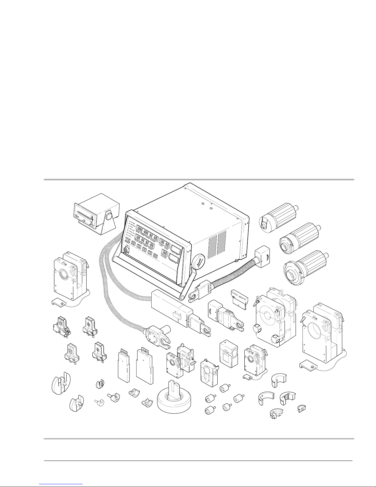
The Swagelok Welding System (SWS) is a versatile, portable and easy to use
orbital welding system. This section includes
D gas tungsten arc welding
D system components
D overview of SWS operation
D specifications.
2005 Swagelok Company, all rights reserved
September 2005
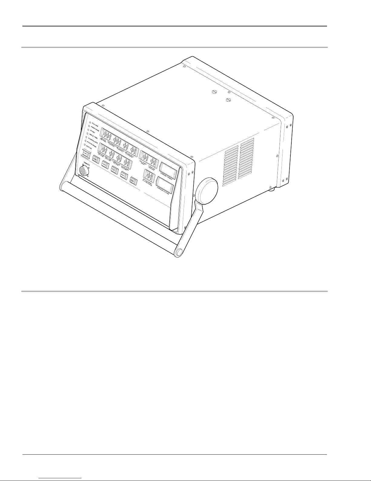
Figure 1-1 Swagelok Welding System
1-1

Introduction
CWS−D100−B Welding System
The purpose of this manual is to familiarize you with the SWS and to provide the
reference information needed to produce high-quality, repeatable welds.
While reading, you may encounter unfamiliar terminology. Some terms are common to
the welding industry and others particular to the SWS. Refer to Appendix A, Glossary,
if necessary.
Gas Tungsten Arc Welding
Principles of the GTAW Process
Gas Tungsten Arc Welding (GTAW) is a welding process that creates an arc between a
nonconsumable tungsten (or tungsten alloy) electrode and the work. The electrode is held
in a torch, rotor, or other device. GTAW uses a shielding gas, most commonly Argon, that
is delivered to the weld area. The shielding gas envelops the weld joint and electrode,
protecting both from contamination by the atmosphere.
The electric arc which creates the weld is produced by the passage of current through the
conductive ionized shielding gas. The arc is established between the tip of the electrode
and the work. Heat generated by the arc melts the base metal. Once the arc and weld
puddle are established, the electrode moves along the joint and the arc progressively melts
the joint surface. Filler wire, if used, is added to the leading edge of the weld puddle to
fill the joint.
GTAW provides precise control of heat input to the weld joint. For this reason, it is
preferred for joining thin gage metals and for making welds close to heat sensitive
components. The process offers advantages to many industries, ranging from the high
purity required in the semiconductor industry to autogenous manual welds of the
process industry.
The process can be used to weld almost all metals. GTAW can be used to weld all types of
joint geometries in tubing, pipe, or other structural shapes. It is particularly appropriate for
welding wall sections less than 3/8 in. (9,5 mm) thick.
GTAW Process Advantages
The GTAW process has the following advantages:
D produces superior quality welds
D allows excellent control of weld penetration
D welds almost all metals
D produces autogenous welds at high speeds
D allows precise control of the welding variables
D welds with or without filler metal
D eliminates spatter
1-2
2005 Swagelok Company, all rights reserved
September 2005

CWS−D100−B Welding System
Process Variables
The major process variables in GTAW are arc current, arc voltage, and travel speed.
D Arc Current − The current measured between the tungsten electrode and the work.
Generally stated, arc current controls the weld penetration.
Direct Current Electrode Negative (DCEN) is common for GTAW. It offers the
advantages of deep penetration and fast welding speeds because most of the heat
generated in the welding process is transferred to the work.
D Arc Voltage − The voltage measured between the tungsten electrode and the work.
Arc voltage is affected by the following:
D arc current
D shape of the tungsten electrode tip
D type and purity of shielding gas
Introduction
D arc length (distance between the electrode and the work)
Arc length is important with this process because it affects the width of the weld
puddle; puddle width is proportional to arc length. The desired arc length is as short
as possible.
D Travel Speed − The speed that the electrode moves over the work while welding.
Travel speed affects both the width and weld penetration of GTAW. Its effect on
width is more pronounced than on penetration. Increasing travel speed decreases the
width of the weld.
Travel speed generally is fixed in mechanized welding. Other variables such as
current or voltage are varied to maintain control of the weld.
2005 Swagelok Company, all rights reserved
September 2005
1-3
Introduction
CWS−D100−B Welding System
System Components
The SWS D100 Power Supply
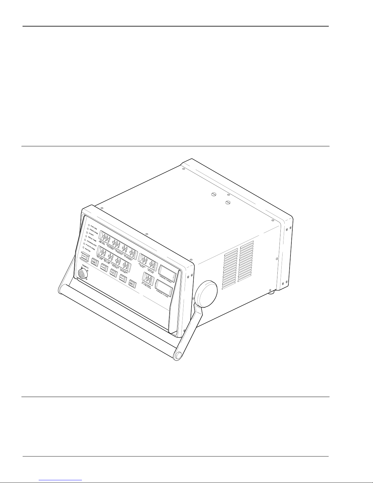
The power supply features microcontroller electronics and closed-loop circuitry to
precisely control output current. Simplified controls and displays provide efficient
programming and monitoring of the welding process.
See Table 1-1 on page 1-9 for the power supply specifications.
Figure 1-2 SWS D100 Power Supply
1-4
2005 Swagelok Company, all rights reserved
September 2005
CWS−D100−B Welding System
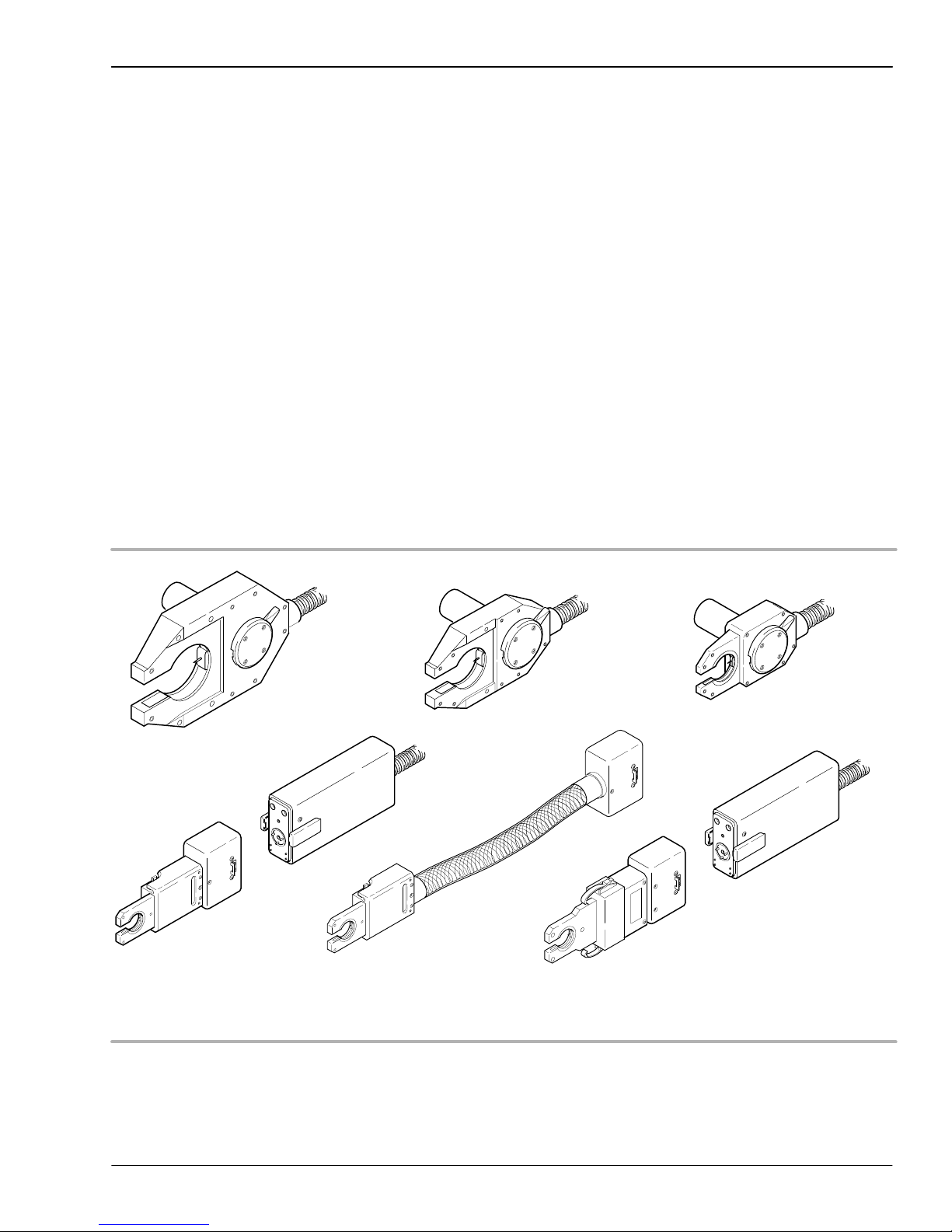
The Weld Head
The SWS weld heads deliver consistent, precise welds for outside diameters from 1/16 in.
to 2 in. (3 mm to 52 mm). There are six weld heads to choose from, depending on the size
of the work pieces. See Figure 1-3.
A dc motor in the weld head drives a rotor which carries the tungsten electrode around the
weld joint. Optical circuitry in the weld head sends precise feedback to the power supply
to control the speed of the rotor.
All moving parts in the weld head mount in low-friction devices to provide smooth,
consistent operation.
A spring-loaded, floating brush continuously contacts approximately one-third of the
circumference of the rotor at all times. This configuration ensures consistent, uniform
electrical conductance to the rotor and electrode.
Introduction
See Table 1-5 on page 1-10 for the weld head specifications.
Series Micro
Motor Module
Series 4 Micro
(Rigid)
Series 4 Micro
(Flexible)
Series 5Series 20 Series 10
Series Micro
Motor Module
Series 8 Micro
2005 Swagelok Company, all rights reserved
September 2005
Figure 1-3 Weld Heads
1-5
Introduction
CWS−D100−B Welding System
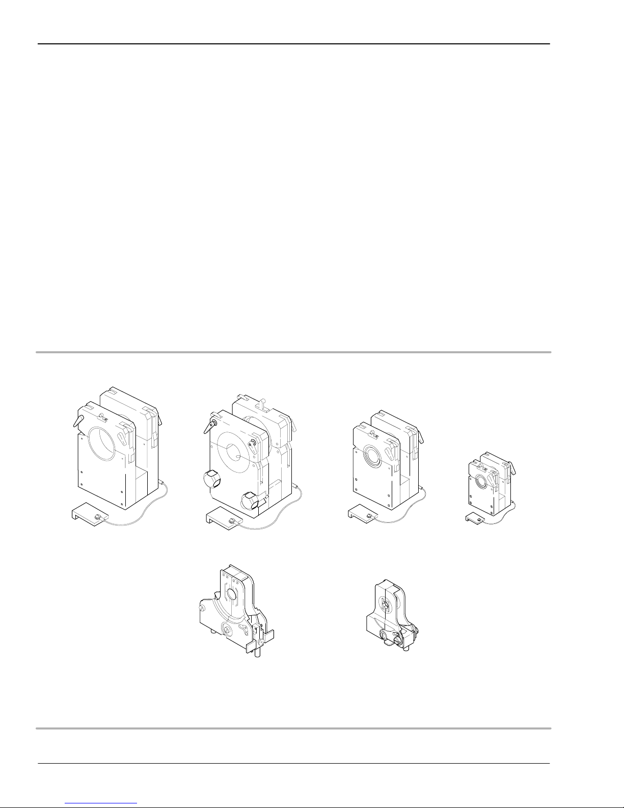
Fixture Blocks
The SWS fixture blocks accurately align and hold tubing, fittings, and valve bodies. The
modular design allows you to select different side plates and create the configuration
needed for the job.
The fixture block is separate from the weld head, allowing work pieces to be easily
aligned and fixtured before welding. The use of multiple fixture blocks offers
increased productivity.
Each fixture block is designed to accommodate a range of work piece sizes. A unique and
patented Universal Collet Insert (UCI) fits into the fixture block to match the diameter of
the work piece. The collet design firmly holds tubing and fittings that vary ± 0.005 in.
(0,13 mm) from nominal outside diameter. Collets are also available for thin wall pipe.
The collets exchange quickly, making the fixture block very adaptable to changing
work requirements. Tables 1-6, 1-7, and 1-8 list the available fixtures and collets.
Series 20-A Series 10
Series 20-B
Series 8
Series 4
Series 5
1-6
Figure 1-4 Standard Fixtures
2005 Swagelok Company, all rights reserved
September 2005

CWS−D100−B Welding System
Overview of SWS Operation
GTAW Orbital welding is a proven method for welding cylindrical shapes such as
tubes, fittings, and pipe. The SWS design makes the orbital welding process efficient
and effective.
The SWS provides an advanced method of autogenous GTAW. The system uses a fixture
block and associated weld head to provide precise fixturing of the work pieces. The
welding parameters are controlled by the SWS power supply and are programmed by
the operator.
Operating the SWS is uncomplicated. The work piece sizes define the fixture block
configuration, collets, and weld head to be used.
The fixture block quickly clamps onto the work pieces. The weld joint is centered in the
fixture block using a centering gage. Since the fixture block is not part of the weld head,
multiple fixture blocks can be used to maximize weld setup efficiency.
Introduction
The weld head cable assembly attaches quickly to the power supply. Setup of the weld
head is limited to the selection of an electrode and setting the arc gap. The arc gap setting
depends on the characteristics of the work pieces. A gage is provided with the weld head
to assist in setting the arc gap. After the arc gap is set, the weld head attaches to the fixture
block and is secured with a locking ring.
The power supply uses rotary switches for weld parameter control. See Figure 1-5. The
appropriate switch settings are generally defined by the work pieces to be welded and are
refined using test welds. The correct settings used for a specific job are developed into a
weld procedure guideline. The guideline is used to maintain repeatability and quality
control for subsequent jobs of the same type.
2005 Swagelok Company, all rights reserved
September 2005
1-7
Introduction
CWS−D100−B Welding System
Figure 1-5 SWS D100 Front Panel Controls
1-8
2005 Swagelok Company, all rights reserved
September 2005

CWS−D100−B Welding System
Specifications
Table 1-1 Power Supply
Model Supply Voltage* Service Amps Output Current (dc)
CWS-D100-1B 115 V (ac) 20 A 2 to 100 A
CWS-D100-1B 115 V (ac) 15 A 2 to 70 A
CWS-D100-2B 230 V (ac) 15 A 2 to 100 A
* 10% input voltage tolerance, frequency range 50 Hz to 60 Hz
Table 1-2 Duty Cycle
Model 6.25 % 60 % 100 %
CWS-D100-1B 100 Amps
14 Volts
CWS-D100-2B 100 Amps
14 Volts
32.3 Amps
11.3 Volts
32.3 Amps
11.3 Volts
25 Amps
11 Volts
25 Amps
11 Volts
Introduction
Duty cycle is the ratio of time the power supply can weld to the time the power supply
must remain idle to cool. The 10 minute cycle is a recognized welding industry standard.
It represents the maximum weld time allowed, with the balance of the 10 minute cycle
required for cooling.
Table 1-3 10 Minute Cycle Times
Maximum Weld TIme
Duty Cycle Rating
30 % 3 7
60 % 6 4
100 % 10 0
(Minutes)
Required Idle Time
(Minutes)
Continually exceeding the duty cycle may activate an internal thermal protector that will
disable the power supply and display message code 50. Refer to pages 3-13 and 3-15.
Table 1-4 Power Supply Dimensions and Weight
Model Dimensions (overall) Weight
CWS-D100-1B 15 1/2 in. (39 cm) wide
20 in. (51 cm) deep
9 in. (23 cm) high (without handle)
CWS-D100-2B 15 1/2 in. (39 cm) wide
20 in. (51 cm) deep
9 in. (23 cm) high (without handle)
42 lbs (19 kg)
45 lbs (20.4 kg)
2005 Swagelok Company, all rights reserved
September 2005
1-9

Introduction
CWS−D100−B Welding System
Table 1-5 Weld Heads
Series Model OD Capacity
4 Micro* CWS-4MRH-A
CWS-4MFH-A
8 Micro* CWS-8MRH 1/4 to 1/2 in.
5 CWS-5H-B 1/8 to 5/8 in.
10 CWS-10H-A 1/4 to 1 in.
20 SWS-20H-B** 1/2 to 2 in.
* Requires CWS-M-MTR-A motor module
** Requires SWS-20TFB-A
1/16 to 1/4 in.
(3 to 6 mm)
(6 to 12 mm)
(3 to 16 mm)
(6 to 25 mm)
(12 to 52 mm)
Table 1-6 Standard Fixture Blocks
Minimum Weld
Model OD Capacity
CWS-4MFA-** 1/16 to 1/4 in.
(3 to 6 mm)
SWS-8MFA-** 1/4 to 1/2 in.
(6 to 12 mm)
CWS-5TFB 1/8 to 5/8 in.
(3 to 16 mm)
CWS-10TFB 1/4 to 1 in.
(6 to 25 mm)
CWS-20TFB 1/2 to 2 in.
(12 to 52 mm)
SWS-20TFB-A 1/2 to 2 in.
(12 to 52 mm)
** Designates size in 1/16ths or mm; 4MFA- includes sizes 01, 02, 04, 3
mm, and 6 mm. 8MF- includes sizes 04, 06, 08, 6 mm, 8 mm, 10 mm,
and 12 mm
Extension Length
1/4 in. (6 mm)
1/4 in. (6 mm)
3/4 in. (19 mm)
3/4 in. (19 mm)
(recessed)
15/16 in. (24 mm)
(no recess)
1 3/8 in. (35 mm)
1.45 in. (37 mm)
1-10
2005 Swagelok Company, all rights reserved
September 2005

CWS−D100−B Welding System
Table 1-7 Special Purpose Fixture Side Plates
Model Used for Comments
CWS-5FSP1
CWS-5FSP2
CWS-5HBDA-BW4
CWS-5HBDA-BW6
CWS-5HBDA-BW6MM
SWS-20FSP1L tubular weld fittings
SWS-20FSP1R tubular weld fittings
* DA − manual actuator only
VCR
, S Type
, VCO
,
VCR
B Type VCO fittings,
and tubing
Micro-Fit fittings
and tubing
BN, DL, DS,
HD, HB, DA* style
valve bodies
and tubing
and tubing
Introduction
weld extension length must be
less than 0.75 in. (19 mm)
requires adapter inserts
requires Micro-Fit fitting collets
1/4 in., 3/8 in., or 6 mm
tubular weld fittings and tubing butt
weld ends
0.80 in. (20 mm) weld
extension length
requires SWS-20UCI-XXTN collets
0.80 in. (20 mm) weld
extension length
requires SWS-20UCI-XXTN collets
Table 1-8 Collets
Model OD Capacity Comments
CWS-5UCI-** 1/8 in. to 5/8 in.
(3 mm to 16 mm)
CWS-5UFCI-.95 n/a fixture collets to hold adapter inserts for
CWS-5UFCI-** 1/8 in. to 5/8 in.
(3 mm to 16 mm)
CWS-5MWCI-04 1/8 in., 1/4 in., 6 mm for Micro-Fit fittings
CWS-5MWCI-06 3/8 in., 8 mm, 10 mm for Micro-Fit fittings
CWS-5MWCI-08 1/2 in., 12 mm for Micro-Fit fittings
CWS-10UCI-** 1/4 in. to 1 in.
(6 mm to 25 mm)
CWS-20UCI-** 1/2 in. to 2 in.
(12 mm to 52 mm)
CWS-20UCI-**P 1/4 in. to 1 1/2 in.
(10.2 mm to 48.3 mm)
SWS-20UCI-**TN 1/2 in. to 2 in.
(12 mm to 52 mm)
SWS-20UCI-MC n/a collet to hold ferrule mandrels for
** − Identifies the collet size in 1/16ths or metric (MM suffix)
tubing
add “mm” suffix for metric sizes.
CWS-5FSP1 side plate
tube collet for special purpose side plates
tubing
tubing
pipe
add J suffix for JIS pipe (-**PJ)
add MMP suffix for metric pipe (-**MMP)
tubular weld fitting collet for
SWS-20FSP1L and SWS-20FSP1R
add MM (MMTN) suffix for metric sizes
SWS-20TFB-A fixture block
2005 Swagelok Company, all rights reserved
September 2005
1-11

Introduction
CWS−D100−B Welding System
Table 1-9 Adapter Inserts for CWS-5FSP1
Model Used for Comments
CWS-5MBVCO-04 316L-4-BVCO-1
316L-4-VCO-1-4TB2
1/4 in. VCR
weld glands
CWS-5FVCR-04 1/4 in. VCR
weld glands
CWS-5FBVCO-04 316L-4-BVCO-3
1/4 in. VCR
weld glands
CWS-5MSVCR-04 6LV-4-SVCR-3 with captured male
CWS-5FSVCR-04 6LV-4-SVCR-3S
6LV-4-SVCR-3
glands must have
overall length of
1.12 in. (28 mm)
or less with
captured male
nut SS-4-SVCR-4
glands must have
overall length of
0.72 in. (18 mm)
or less with
captured female
nut SS-4-VCR-1
glands must have
overall length of
0.77 in. (20 mm)
or less with
captured female
nut SS-4-VCR-1
nut SS-4-SVCR-4
with captured female
nut SS-4-SVCR-1
WARNING!
DO NOT USE EXTENSION
CORDS THAT ARE IN POOR
PHYSICAL CONDITION OR
HAVE INSUFFICIENT
CURRENT CAPACITY.
FAILURE TO DO SO
CAN POSE FIRE AND
SHOCK HAZARDS.
Table 1-10 Extension Cords
Wire gauge
0 ft to 50 ft
Model Supply Voltage
CWS-D100-1B 115 V (ac) #12 AWG
CWS-D100-2B 230 V (ac) #12 AWG
Some power loss will occur, depending on the length of the extension
cord. See Table 1-10 to determine the minimum wire size to use.
(0 m to 15 m)
(2,5 mm)
(2,5 mm)
Wire gauge
50 ft to 100 ft
(15 m to 30 m)
#10 AWG
(4,0 mm)
#10 AWG
(4,0 mm)
1-12
2005 Swagelok Company, all rights reserved
September 2005

Section 2
Installation
Introduction
This section describes the procedures necessary for
installing the Swagelok Welding System (SWS). This
section includes:
D tools and accessory requirements
D electrical requirements
D unpacking and inspecting system components
D installing the SWS
D installing the gas delivery system
D preliminary check.
2005 Swagelok Company, All rights reserved
September 2005
2-1

Installation
CWS−D100−B Welding System
Tools and Accessory
Requirements
You need the following tools and accessories to install and
operate your SWS.
Tool/Accessory Included? Provided With
Hex Wrenches (0.050 in. to 5/32 in.) Yes Weld Head
Electrode Package Yes Weld Head
Arc Gap Gage Yes Weld Head
Flat Blade Screw Driver Yes Weld Head
Centering Gage Yes Fixture Block
Quick−Connect Stem Yes Power Supply
Secondary Solenoid Bypass Plug Yes Power Supply
Dial/Digital Calipers or Micrometer No −
Purge Connector(s) No −
(3)
(1)
(2)
No −
No −
No −
Shielding/Purge gas lines
Shielding/Purge Gas Source
Pressure Regulator
Internal Purge Gas Flow Meter No −
Shielding Gas Flow Meter No −
(1)
All lines used for shielding/purge gas should be the low moisture
absorption type.
(2)
A compressed gas bottle or liquid Dewar source can be used.
Argon is the gas most frequently used.
(3)
A two-stage gas regulator is suggested. The regulator should
reduce the source pressure to 25 psig to 50 psig (1.9 bar to
3.5 bar) for the arc shielding and internal (backing) purge
flow meters.
2-2
2005 Swagelok Company, All right reserved
September 2005

CWS−D100−B Welding System
Electrical Requirements
Input Voltage
Table 2-1 lists the electrical requirements for the
power supply.
Table 2-1 Power Supply Electrical Requirements
Installation
Power Supply
Model
CWS-D100-1B 115 V* (ac) 20 A
CWS-D100-2B 230 V (ac) 15 A
* If the input voltage is 100 V or less, the output power
capabilities may be reduced.
Voltage
Requirement
Service Current
Ensure that the following guidelines are adhered to
when considering the electrical requirements for the
power supply:
D All wiring and related components must
be installed according to local and
National Electrical Codes.
D The power supply must be grounded.
D A dedicated electrical circuit must be used.
Using an Extension Cord
WARNING!
THE POWER SUPPLY MUST
BE GROUNDED. IF IT IS NOT
GROUNDED, ELECTRIC
SHOCK CAN OCCUR.
If it is necessary to use an extension cord, follow
these guidelines:
D The wire size must meet the specifications
indicated in Table 1-10, located in
Section 1, Introduction.
D If the length of the cord is greater than 100 ft,
call your Swagelok representative for
recommended guidelines.
2005 Swagelok Company, All rights reserved
September 2005
Note: The voltage drop in an
extension cord 100 ft long may
affect the output performance of
the SWS.
2-3

Installation
CWS−D100−B Welding System
Unpacking and Inspecting
System Components
Unpacking the Power Supply
The SWS power supply is packaged in a wooden shipping
container. See Figure 2-1. The power supply part number
and serial number are located on a label on the outside of
the container.
Note: Keep the shipping container
and the foam inserts for storing
and/or shipping.
Table 2-2 lists the contents of the shipping container.
Table 2-2 Shipping Container Contents
Part Description Part No. Qty.
Welder Power Supply CWS-D100-*B 1
Power Cord CWS-CORD-* 1
1/4 in. Male QC SS-QC4-S-400 1
Secondary Solenoid Bypass Plug − 1
Swagelok Welding System
User’s Manual
* Denotes Model ** Denotes Language
CWS-MANUAL-D100B-** 1
Remove the contents of the shipping container by
performing the following steps:
1. Remove the following items:
D Swagelok Welding System User’s Manual
D Swagelok Quick-Connect stem
D secondary solenoid bypass plug
D power cord
Figure 2-1 Shipping Container
2-4
2. Remove the power supply by lifting it by the handle.
Remove the side foam inserts. Place the power supply
on a stable cart, platform, or table.
3. Check the power supply and accessories for damage.
4. Check that the serial number on the rear panel of the
power supply matches the serial number on the
shipping container label.
5. Record the model and serial numbers, and the
delivery dates on page i of the Forward section of
this user’s manual.
2005 Swagelok Company, All right reserved
September 2005

CWS−D100−B Welding System
Unpacking the Weld Head Cable
Assembly and Related Components
The following weld head components are packaged in a
foam-lined shipping container:
D weld head assembly
D arc gap gage
D electrode package
D tool package
1. Inspect the container for damage.
2. Remove the components from the container.
Installation
3. Check the items for any damage.
4. Verify that the weld head serial number matches the
serial number on the shipping container.
5. Record the model and serial numbers, and the
delivery dates on page i of the Forward section of
this user’s manual.
2005 Swagelok Company, All rights reserved
September 2005
2-5

Installation
CWS−D100−B Welding System
Installing the SWS
To get the maximum performance and reliability from your
SWS, it must be set up and installed properly.
Figure 2-2 Power Cord Receptacle
This section describes how to
D install the power supply
D install the weld head.
Installing the Power Supply
To install the power supply, follow these steps:
1. Place the power supply in a position such that the front
and rear panel controls are easily accessible.
2. Locate the power cord. Insert the cord into the polarized
receptacle on the rear of the power supply. See
Figure 2-2.
3. Tighten the connector lock at the base of the receptacle
to secure the cord in the receptacle.
Figure 2-3 Power Supply Circuit
Breaker in the OFF Position
4. Ensure that the power cord reaches an electrical outlet.
Do not connect the power cord to the outlet at this time.
5. Turn off the circuit breaker. Refer to Figure 2-3.
2-6
2005 Swagelok Company, All right reserved
September 2005

CWS−D100−B Welding System
Installation
Installing the Weld Head
The weld head assembly has four connectors that plug into
the power supply. See Figure 2-4.
The four connectors on the cable are
D fixture
D electrode (red)
D work (green)
D weld head shielding gas.
Connect the four connectors to the rear panel of the power
supply by performing the following steps (see Figure 2-5):
1. Locate the weld head assembly.
Fixture
Electrode
Work
Weld Head
Shielding Gas
Figure 2-4 Weld Head Assembly
2005 Swagelok Company, All rights reserved
September 2005
Figure 2-5 Weld Head Connectors
2-7

Installation
CWS−D100−B Welding System
Caution!
Ensure that the fixture
connector is fully seated in
the mating socket and the
threaded sleeve is tight.
Note: The weld head shielding
gas connector must be a
single-end shut-off (SESO)
Swagelok Quick-Connect
stem (SS-QC4-S-400).
2. Align the notch on the multi-pin connector with the
small tab in the mating socket on the rear panel labelled
FIXTURE. Insert the connector in the socket. Turn the
connector sleeve clockwise by hand until it is tight.
This connection provides the control signals to drive
the weld head.
3. Insert and fully seat the red connector into the socket
on the rear panel labelled
ELECTRODE. Twist the
connector 1/4-turn clockwise to lock it into place. This
connection is the negative (−) output terminal of the
weld head.
4. Insert the green connector into the socket on the rear
panel labelled
WORK. Twist the connector 1/4-turn
clockwise to lock it into place. This connection is the
positive (+) output terminal of the weld head.
5. Insert the weld head shielding gas connector
into the Swagelok Quick-Connect stem labelled
TO WELD HEAD. Ensure that the connector is firmly
attached. This connection provides shielding gas to the
weld head through a solenoid valve in the power supply.
2-8
2005 Swagelok Company, All right reserved
September 2005

CWS−D100−B Welding System
Installing the Gas
Delivery System
Introduction
The Gas Delivery System reduces oxidation or
contamination to the weld puddle, tungsten electrode,
and Heat Affected Zone (HAZ).
There are two types of gas delivery systems
commonly used:
D typical Gas Delivery System
Refer to the installation procedure beginning on
page 2-10.
Installation
D gas delivery system using a secondary shielding
gas solenoid valve
Refer to the installation procedure beginning on
page 2-12.
2005 Swagelok Company, All rights reserved
September 2005
2-9

Installation
CWS−D100−B Welding System
Installing the Typical Shielding/Purge
Gas Delivery System
Install the Shielding/Purge Gas Delivery System. Figure 2-6
shows a typical system. Be sure to adhere to the
following precautions:
D Ensure that the gas storage container(s) are secured
before using them.
D Ensure all connections are tight and do not leak.
D Use only a Swagelok single-ended shut-off
Quick-Connect stem on the shield/purge line
for the shielding gas connector.
D Adjust the low-pressure regulator gage to reduce
the gas storage container source pressure to 25 psig
to 50 psig.
When complete, continue to the Preliminary Check
procedure beginning on page 2-14.
2-10
2005 Swagelok Company, All right reserved
September 2005

CWS−D100−B Welding System
Installation
High Pressure Gage
(0 psig to 3000 psig)
Inert
Gas Cylinder
Purge Fitting
(Swagelok Union or
Reducing Union with Nylon
Ferrules or Ultra-Torr
2-stage Regulator
Tubing to be Welded
Low Pressure Gage
(0 psig to 150 psig)
Internal Purge
Gas Shut-Off Valve
)
SWS Fixture Block
Flow Meter for Internal
Purge Gas (Range
3
0 std ft
/h to 30 std ft3/h)
Supply
Manifold
Purge Fitting
(Swagelok Union or Reducing Union
with Nylon Ferrules or Ultra-Torr
for Purge Gas Restriction)
Flow Meter for Shielding Gas
(Range 0 std ft
3
/h to 50 std ft3/h)
Shielding Gas
Supply Inlet
SWS Power Supply
Figure 2-6 Typical Gas Delivery System
2005 Swagelok Company, All rights reserved
September 2005
2-11

Installation
CWS−D100−B Welding System
Installing the Optional Gas
Delivery System
The optional gas delivery system is generally used in
Ultra High Purity (UHP) gas systems where quick connects
are not permitted. This type of system uses an external
12 V (dc) secondary solenoid valve instead of using the
solenoid valve located inside the power supply. If necessary,
the secondary solenoid valve may be the high purity type.
Caution!
Do not insert the secondary
solenoid bypass plug into
the connector unless you are
using a secondary solenoid.
Inserting the plug disables
the power supply solenoid.
A secondary solenoid bypass plug is inserted in the
EXT GAS CONTROL connector on the rear panel to disable
the solenoid inside the power supply and provide +12 V to
control the secondary solenoid.
For the gas delivery system using a secondary shielding gas
solenoid valve, locate the:
D secondary solenoid bypass plug
D secondary shielding gas solenoid valve
D 1/4-turn internal purge gas shut-off valve.
Refer to Figure 2-7. Install the optional gas delivery system.
Be sure to adhere to the following precautions:
D Ensure that the gas storage container(s) are secured
before using them.
D Ensure all connections are tight and do not leak.
2-12
D Observe correct polarity on the secondary solenoid
bypass plug.
D Adjust the low pressure regulator gage to reduce
the gas storage container source pressure to
25 psig to 50 psig.
2005 Swagelok Company, All right reserved
September 2005

CWS−D100−B Welding System
Installation
SWS Fixture Block
SWS Power
Supply
Weld Head
Internal Purge Gas
Shut-Off Valve
Shielding Gas
Flow Meter
Secondary
Solenoid
Valve
Secondary Solenoid
Bypass Plug
2-stage Regulator
Supply
Manifold
Inert Gas
Cylinder
Internal
Purge Gas
Flow Meter
Figure 2-7 Optional Gas Delivery System
Secondary Solenoid
Bypass Plug
2005 Swagelok Company, All rights reserved
September 2005
2-13

Installation
CWS−D100−B Welding System
Preliminary Check
Before placing the SWS into operation, you should check
that the power supply is operating correctly.
To check the system, follow these steps:
1. Connect the power supply power cord to an
electrical outlet.
2. Turn on the power supply circuit breaker. After a
2 second to 4 second delay, the following is displayed:
D Blinking decimal point followed by a zero in
the Average Current and Average Voltage
displays on the power supply front panel.
See Figure 2-8.
Figure 2-8 Average Current and
Voltage Displays
D The amber-colored Fixture indicator light is
on indicating that the fixture block is not
attached to the weld head. See Figure 2-9.
If the power supply does not come on, refer to Section 7,
Troubleshooting, for a list of possible causes and
corrective actions.
Figure 2-9 Weld Status
Indicator Lights
2-14
2005 Swagelok Company, All right reserved
September 2005

CWS−D100−B Welding System
3. Position the weld head such that the rotor can be easily
seen. See Figure 2-10.
Installation
4. Press
STOP/RESET on the front panel.
D For series 5, 10, and 20 Weld Heads, the
rotor should make one-half of a rotation
(180° position) in the head. See Figure 2-11.
D For the micro head, the rotor should make one
complete rotation in the head.
5. Press
STOP/RESET on the front panel to return the rotor
to its home position.
6. Turn off the power supply.
If problems occur, refer to Section 7, Troubleshooting, for a
list of possible causes and corrective actions.
Rotor
Figure 2-10 Positioning the Weld
Head to View the Rotor Rotation
Note: The rotor must be returned to
its home position before welding.
2005 Swagelok Company, All rights reserved
September 2005
Figure 2-11 Checking the
Rotor Rotation
2-15

Installation
CWS−D100−B Welding System
2-16
2005 Swagelok Company, All right reserved
September 2005

Section 3
Operation
Introduction
This section describes the basic operation of the Swagelok
Welding System (SWS). This section includes
D front panel controls
D SWS modes of operation
D installing the electrode in the
Series 5/10/20 Weld Head
D setting the arc gap
D preparing the work
D fixturing the work
D connecting the weld head
to the fixture block
D entering the weld parameters
D setting the shield gas flow
D starting and completing the weld.
The description of the welding process in this section
uses a weld procedure guideline based on tubing with a
1/2 in. OD and 0.049 in. wall thickness. Remember that a
weld procedure guideline is a list of weld parameter settings
that have been determined for a particular job. Keep in mind
that the weld parameters listed in this section may not
produce an optimum weld since the purpose of this section
is to demonstrate the operation of the SWS. Section 5,
Weld Parameter Adjustment, describes how to optimize
welding parameters.
2005 Swagelok Company, all rights reserved
September 2005
3-1

Operation
CWS−D100−B Welding System
Front Panel Controls
20
7
8
21
1. Impulse rotary switch
2. Maintenance rotary switch
3. Impulse Rate rotary switch
4. Impulse Width rotary switch
5. Arc Start rotary switch
6. Duration rotary switch
7. Prepurge rotary switch
1 2 3 4 5 6
16 17 18 1914
15
8. Weld Time rotary switch
9. Downslope rotary switch
10. Postpurge rotary switch
11. Rotor Speed rotary switch
12. Average Current display
13. Average Voltage display
14. Start pushbutton
12
13
10
9
11
15. Downslope pushbutton
16. Purge pushbutton
17. Rotor Jog pushbutton
18. Print pushbutton
19. Stop/Reset pushbutton
20. Status indicator lights
21. Remote Pendant connector
3-2
Figure 3-1 Front Panel Controls
You operate the SWS by using pushbuttons and rotary
switches on the front panel of the power supply. The values
you program into the rotary switches are determined by the
weld procedure guidelines.
The front panel digital displays monitor the welding process
and show message code information. Message codes are
numbers that indicate weld parameter setup errors, power
supply status, etc.
The status indicator lights on the front panel show the
welding process sequence or flash a warning if the power
supply detects that a weld parameter is set incorrectly.
2005 Swagelok Company, All rights reserved
September 2005

CWS−D100−B Welding System
Current Control Switches
The current control switch group determines the
characteristics of the current output of the power supply
during a weld cycle. See Figure 3-2. The controls
function as follows:
D IMPULSE (High Amps) sets the maximum current output
used during the weld cycle. The impulse setting affects
the depth of penetration of the weld profile.
D MAINTENANCE (Low Amps) sets the minimum current
output used during the weld cycle. This is the current
level required to
D maintain the arc
D provide enough background heat to maintain the
weld puddle.
Operation
D IMPULSE RATE (Pulses/Sec) sets the number of changes
per second between the Impulse and Maintenance
current levels during the weld cycle.
D IMPULSE WIDTH (% of Impulse) sets the percentage of
time the current is at the Impulse current level for each
Impulse/Maintenance cycle.
D ARC START (Amps) sets the output current during the
duration period. This current level
D helps stabilize the initiated arc
D develops the weld puddle.
Figure 3-2 Current Controls
2005 Swagelok Company, all rights reserved
September 2005
3-3

Operation
CWS−D100−B Welding System
Timing Control Switches
The timing control switch group determines the weld cycle
timing. See Figure 3-3. The controls function as follows:
D PREPURGE (Seconds) is the time in which shielding gas
flows through the weld head and around the weld joint
before the arc is initiated.
D DURATION (Seconds) is the length of time between
the arc start period and the beginning of the weld
time cycle.
D The current specified on the arc start rotary switch
is maintained during this time.
D The rotor does not move during this time.
D WELD TIME (Seconds) is the actual welding time at the
average current. During the weld time, the output
current cycles between the impulse and maintenance
levels at the impulse rate and impulse width entered.
Figure 3-3 Timing Controls
D During this time, the rotor moves at the speed
specified by the rotor speed rotary switch.
D The weld time cycle forms the main body of
the weld.
D DOWNSLOPE (Seconds) is the time during which the
average weld current uniformly decreases until the arc
is extinguished.
D During this time, the rotor continues to move at the
speed specified by the rotor speed rotary switch.
D The downslope cycle reduces the chance of
weld cracking.
3-4
2005 Swagelok Company, All rights reserved
September 2005

CWS−D100−B Welding System
D POSTPURGE (Seconds) is the amount of time the
shielding gas continues to flow through the weld head
and around the weld joint after the arc is extinguished.
This gas flow prevents oxidation and contamination of
the weld bead and electrode while the work is cooling.
D ROTOR SPEED (% of Max Speed) is expressed as a
percentage of the maximum RPM that the rotor can
attain. A rotor speed setting of 99 gives the maximum
RPM for the weld head. See Table 3-1.
Table 3-1 Maximum Rotor Speed by
Weld Head Model
Maximum
Rotor Speed
Weld Head Model
Micro Weld Head 24 2.5
Series 5/10 Weld Head 12 5
Series 20 Weld Head 6 10
(RPM)
Seconds/
Revolution
Operation
Note: A minimum of 10 seconds
PREPURGE is recommended for all
SWS Weld Head models. If Weld
Head extension cables are used,
add one second for each foot of
cable added.
2005 Swagelok Company, all rights reserved
September 2005
3-5

Operation
CWS−D100−B Welding System
Pushbuttons
The front panel pushbuttons control the welding operation
and provide some manual control functions for the weld
head. See Figure 3-4. The pushbutton functions are
as follows:
D START initiates the welding sequence.
D DOWNSLOPE initiates the downslope cycle when pressed
during the weld time cycle. The downslope cycle
reduces the output current levels from the weld time
levels to zero during the time specified.
D STOP/RESET aborts the weld and halts the rotor if
pressed during the weld cycle. Push
to return the rotor to its home position as shown in
Figure 3-5 on page 3-7. The rotor will move at
maximum speed when traveling to the home position,
regardless of the programmed rotor speed. When not
welding, pushing
STOP/RESET causes the rotor to rotate
as shown in Table 3-2.
STOP/RESET again
Figure 3-4 Pushbuttons
Note: The external gas solenoid
referenced here may be used in
place of the internal solenoid
at the user’s option.
See Section 2, Installation, for
installation information.
Table 3-2 Stop/Reset Rotor Travel
Weld Head Model Rotor Travel
Micro Weld Head 1 Revolution
Series 5, 10, 20 1/2 Revolution
(no Fixture Block connected)
1 Revolution
(with Fixture Block connected)
D PURGE activates the internal solenoid valve or the
optional external gas solenoid valve and starts the flow
of shielding gas to the weld head. See Note. When
PURGE is depressed, shielding gas flows to the weld
head until you press the pushbutton again. The
pushbutton overrides the prepurge and postpurge timers
and allows shielding gas to continuously flow through
the weld head.
3-6
2005 Swagelok Company, All rights reserved
September 2005

CWS−D100−B Welding System
D ROTOR JOG advances the rotor manually. Press
and hold the pushbutton to move the rotor. Release
the pushbutton to stop the rotor.
ROTOR JOG can be
used to position the rotor for electrode replacement or
adjustment. The rotor will move at the speed defined
by the
D PRINT causes the power supply controller to transmit
ROTOR SPEED rotary switches.
weld data to the printer port on the rear of the unit. The
optional CWS-DRP printer accepts the data and prints
the record.
Operation
Figure 3-5 Rotor Home Position
2005 Swagelok Company, all rights reserved
September 2005
3-7

Operation
Figure 3-6 Status Indicator Lights
CWS−D100−B Welding System
Status Indicator Lights
The status indicator lights monitor certain elements of the
power supply operation. See Figure 3-6.
The conditions monitored by some of the indicators are
independent of the welding process. Most of the indicators
light during the welding process to show the control
sequence executed by the power supply. The control
sequence is affected by the values entered into the timing
control switches.
The lights also notify you if any weld parameter settings
exceed pre-defined limits. See Figure 3-8 for an example.
D Fixture indicates whether or not the weld head is
properly attached to the fixture block. If it is not
connected, the indicator light is on. The power supply
will not start a weld cycle when this indicator light
is on.
Caution!
DO NOT try to remove the
fixture block from the weld
head until all status indicator
lights are off.
D Prepurge indicates the prepurge cycle is active. The
Prepurge cycle occurs prior to arc start. This light
indicates that the shielding gas solenoid valve in the
power supply is energized, allowing the shielding gas to
flow to the weld head prior to starting the
welding cycle.
D Start indicates the power supply is in the arc start
portion of the weld cycle.
D Weld time indicates the weld cycle is in progress.
D Downslope indicates the downslope cycle is
in progress.
D Postpurge indicates the postpurge cycle is in progress.
The shielding gas continues to flow to the weld head,
and the rotor moves to the home position.
D Rotor indicates the rotor is in motion.
3-8
2005 Swagelok Company, All rights reserved
September 2005

CWS−D100−B Welding System
Digital Displays
The digital displays monitor system operation during
welding and provide message code information. See
Figure 3-7. The display functions are as follows:
D Average Current indicates the average arc current
measured during the weld sequence.
D Average Voltage indicates the average arc voltage
measured during the weld sequence.
The average voltage displayed during a weld cycle
varies with the arc gap, type of shielding gas, current
output, etc., but typically is in the 5 V to 15 V range.
The Average Current and Average Voltage displays are
also used for programming and displaying message codes.
See SWS Modes of Operation.
Operation
SWS Modes of Operation
The front panel controls serve two purposes. In addition to
controlling the weld parameters and weld sequences, the
controls are used to access the modes of the power supply.
The power supply has three modes of operation:
D operational
D program
D test
Each mode uses message codes to perform a variety of
functions. Generally, the message codes are grouped by
mode. Operational mode uses codes 1 to 11, 41, 42, 50,
and 51. Program mode uses 20 to 23, 30 to 35, 60 to 63,
and 99. Test mode uses 97 and 98.
The message codes are explained in detail later in
this section.
Figure 3-7 Digital Displays
Table 3-3 shows all the message codes used by the power
supply. Note that certain code ranges are marked Factory
Use. These codes, except for 64 to 96, are normally not
used, which is noted in the table.
2005 Swagelok Company, all rights reserved
September 2005
3-9

Operation
CWS−D100−B Welding System
Table 3-3 SWS Message Codes
Code No. Name
Normal
Operating
Range
Mode or
Setting to
Activate
Code Type
01 Impulse 2 A to 99.9 A < 2 Disable*
02 Maintenance 2 A to 99.9 A < 2 Disable*
03 Impulse Rate 1 Hz to 99 Hz < 1 Caution
04 Impulse Width 5 % to 95 % < 5 or > 95 Disable*
05 Arc Start 2 A to 99 A < 2 Disable*
06 Duration 0.0 to 5.0 > 5.0 Disable*
07 Prepurge 1 s to 99 s < 1 Caution
08 Weld Time 1 s to 99 s < 1 Disable*
09 Downslope 1 s to 99 s < 1 Disable*
10 Postpurge 1 s to 99 s < 1 Caution
11 Rotor Speed 5 % to 99 %
≥ 1 or < 5
Caution
< 1 Disable*
12 to 19 Factory use Not used
20 Resettable weld
counter
21 Automatic print
counter
0 to 9999 Program
mode
0 to 99 Program
mode
Programmable
Programmable
22 Enable signal
polarity
23 Arc Start power 0=low
0=low
1=high
1=normal
Program
mode
Program
mode
Programmable
Programmable
24 to 29 Factory use Not used
30 Time - hours 0 to 24 Program
Programmable
mode
31 Time - minutes 0 to 59 Program
Programmable
mode
32 Date - month 1 to 12 Program
Programmable
mode
33 Date - day 1 to 31 Program
Programmable
mode
34 Date - year 2 digit
00=2000
35 Date printing
format
0=mm/dd/yy
1=dd/mm/yy
Program
mode
Program
mode
Programmable
Programmable
36 to 40 Factory use Not used
41 Paper out No paper
Caution
installed with
printer
power on
3-10
2005 Swagelok Company, All rights reserved
September 2005

CWS−D100−B Welding System
Operation
Normal
Operating
Code No. Name
Range
42 Printing Data is
Mode or
Setting to
Activate
Code Type
Information only
transferred
to printer
port
43 to 49 Factory use Not used
50 Hi-temp Excessive
Disable*
internal
power
supply
temperature
51 Old head type No weld
Disable*
head or
non-safety
interlocked
weld head
connected
52 Rotor jam Rotor motion
impeded
Disable*
See Note (A)
53 to 59 Factory use Not used
60 Non-resettable
weld counter
61 Arc start
attempts
62 System serial
number
63 System
software
Program
mode
Program
mode
Program
mode
Program
mode
Information only
Information only
Information only
Information only
version
64 to 96 Factory use See Note (B)
97 Test switches/
Test mode
pushbuttons
98 Test indicator
Test mode
lights/displays
99 Print user
parameters
Program
mode
* The Prepurge, Start, Weld Time, Downslope, and Postpurge status
indicator lights are flashing.
Note (A): Press
again unless
STOP/RESET to clear the error. Rotor will not move
STOP/RESET is pressed a second time.
Note (B): Service may be necessary. Call your
Swagelok representative.
2005 Swagelok Company, all rights reserved
September 2005
3-11

Operation
CWS−D100−B Welding System
Operational Mode
When the power supply is turned on it enters the operational
mode. The Average Current and Average Voltage displays
show a blinking decimal point and a zero. If the weld head
is not attached to a fixture block, Fixture is on. The power
supply is ready to be used.
Weld Parameter Limits (Message codes 1 to 11)
Each front panel rotary switch controls a part of the welding
process. The power supply operates normally as long as
each switch setting is within certain limits. If the limits are
exceeded, the power supply reacts to the condition and
shows a message code on the front panel displays. If the
code display is accompanied by flashing status indicator
lights, a “disable” condition exists. If not, the code display
indicates a “caution” condition.
Message codes 1 to 11 refer to the front panel rotary
switches by number. See Table 3-4. See Figure 3-1 to
cross reference the switch position numbers.
Table 3-4 Weld Parameter Limit Message Codes
Normal
Operating
Code No. Name
01 Impulse 2 A to 99.9 A < 2 Disable*
02 Maintenance 2 A to 99.9 A < 2 Disable*
03 Impulse Rate 1 Hz to 99 Hz < 1 Caution
04 Impulse Width 5 % to 95 % < 5 or > 95 Disable*
05 Arc Start 2 A to 99 A < 2 Disable*
06 Duration 0.0 to 5.0 > 5 Disable*
07 Prepurge 1 s to 99 s < 1 Caution
08 Weld Time 1 s to 99 s < 1 Disable*
09 Downslope 1 s to 99 s < 1 Disable*
10 Postpurge 1 s to 99 s < 1 Caution
11 Rotor Speed 5 % to 99 %
Range
Mode or
Setting to
Activate
≥ 1 or < 5
< 1 Disable*
Code Type
Caution
3-12
* The Prepurge, Start, Weld Time, Downslope, and Postpurge status
indicator lights are flashing.
2005 Swagelok Company, All rights reserved
September 2005

CWS−D100−B Welding System
Disable Condition
The power supply enters a “disable” condition when a
serious fault exists or a front panel control is set to a value
that could damage the system. The power supply will not
start in a “disable” condition. The rotor can still be moved
while the “disable” condition exists, using
ROTOR JOG. The power supply shows the “disable”
STOP/RESET or
condition by flashing the status indicator lights shown in
Figure 3-8 and flashing a message code on the Average
Current and Average Voltage displays. The code shows
you what rotary switch is misprogrammed.
Caution Condition
A “caution” condition indicates that a front panel parameter
setting is questionable. The power supply is not disabled
and can weld if a “caution” exists. The front panel indicates
a “caution” condition by flashing a message code on the
Average Current and Average Voltage displays. The code
shows you which rotary switch has the questionable value.
Interpreting the Message Codes
Operation
Figure 3-8 Disable Condition
The power supply shows the switch setting problem by
displaying the switch code on the Average Voltage display.
Codes 1 to 11 use the Average Current display to show the
limit for the switch identified by the Average Voltage
display. Code numbers 41 and above in the Average
Voltage display are system status information or errors
detected by the power supply.
See Figure 3-9. The Average Voltage display shows that
rotary switch position 04 has an incorrect value. Refer to
Figure 3-1 and note that the switch labeled 04 is the
switch. The position of the dash indicates which limit
WIDTH
IMPULSE
is exceeded, minimum or maximum. Figure 3-9(A) shows
the dash on the left, indicating that the setting is too low.
Figure 3-9(B) shows the dash on the right, indicating the
setting is too high.
The Average Current display shows the limit for the
parameter. Whether the limit displayed is a minimum or
maximum depends on the position of the dash in the other
display. Figure 3-9(A) shows the low limit for
is 5. Figure 3-9(B) shows the high limit for IMPULSE
WIDTH
is 95.
WIDTH
IMPULSE
2005 Swagelok Company, all rights reserved
September 2005
3-13

Operation
CWS−D100−B Welding System
A
Dash on left indicates below minimum
Figure 3-9 Digital Display Examples for the Operator/Machine Interface
B
Dash on right indicates above maximum
Multiple Disable or Caution Conditions
The power supply displays multiple errors on the digital
displays one after another. Each message code is displayed
for a moment, followed by the next, until all are shown. The
sequence repeats continuously until the errors are cleared.
If the message code is caused by a “disable” condition, the
status indicator lights blink as the code is displayed.
3-14
2005 Swagelok Company, All rights reserved
September 2005

CWS−D100−B Welding System
System Status/Faults (Message codes 41 to 52)
41 Paper out
Code 41 indicates that the optional printer is out of paper.
See Appendix B, Optional Equipment, for information on
the printer.
42 Printing
Code 42 appears when a print cycle is started. The power
supply outputs data to the optional printer. This code only
shows that the data is being sent to the printer. The power
supply does not monitor the printer operation.
50 Hi-temp
Operation
Code 50 is a “disable” condition that is not resettable. The
condition occurs when a temperature sensor inside the
power supply detects a buildup of heat that exceeds a
predefined limit. The power supply is disabled until the
internal temperature drops to a safe level. Allow the power
supply to cool. After the condition clears, welding
can resume.
51 Old head type
Code 51 is a “disable” condition. The code is displayed if
the power supply does not detect a safety interlocked weld
head. The code is displayed if no weld head is connected or
if a nonsafety interlocked weld head is connected.
52 Rotor jam
Code 52 is a “disable” condition. The condition occurs if the
power supply senses that the rotor motion is impeded. The
power supply monitors the rotor when a move command is
given. If no motion is detected, the code is displayed, and
the system is disabled.
2005 Swagelok Company, all rights reserved
September 2005
3-15

Operation
Figure 3-10 Display Readout for
Example 1
CWS−D100−B Welding System
Let’s look at two examples:
EXAMPLE 1 − Disable Condition
Suppose a weld procedure guideline is keyed in and
IMPULSE is set to 1 A. The minimum allowable Impulse
setting (message code 01) is 2 A, so the power supply is
disabled and the status indicator lights begin to flash.
Pressing
moved with
ST ART has no effect. The rotor can still be
ROTOR JOG or STOP/RESET.
The digital displays read as shown in Figure 3-10.
The Average Voltage display shows that switch one
(Impulse) is below its minimum allowable setting
(dash on left). The Average Current display shows
the minimum limit is 2 A.
By changing the value of the Impulse switch to 2 A
or greater, the condition is corrected and the
operation can proceed. The correct Impulse value can
only be determined by developing a proper weld
procedure guideline.
Figure 3-11 Display Readout for
Example 2
EXAMPLE 2 − Caution Condition
A weld procedure guideline is keyed in and Prepurge
is set to zero seconds. You may wish to use a
continuous purge, so the prepurge timer is not needed.
The minimum prepurge setting (message code 07) is
one second. According to Table 3-3, code 07 will not
disable the power supply, so entering zero creates a
“caution” condition.
The digital displays read as shown in Figure 3-11.
The Average Voltage display shows that switch 7
(Prepurge) is below its normal limit (dash on left).
The Average Current display shows the minimum
limit is one.
The unit is still functional. This condition only serves to
show that there is a questionable setting. If
ST ART is
pushed, the system begins welding, and the weld
current and voltage are displayed. After completing the
weld, the digital displays again indicate the caution
condition. When Prepurge is changed to one second or
greater, the displays return to normal.
3-16
2005 Swagelok Company, All rights reserved
September 2005

CWS−D100−B Welding System
Program Mode
The program mode accesses setup parameters for the power
supply and the optional printer. The program mode also
serves as an access path for the test mode. See “Test Mode”
on page 3-22.
Entering Program Mode
Refer to Figure 3-12. Do the following to enter
program mode:
Operation
1. Press and hold
2. Press and hold
DOWNSLOPE.
ROTOR JOG.
3. Release both pushbuttons at the same time.
The status indicator lights begin to sequence up and
down, indicating that the program mode has been
successfully entered.
Selecting Program Items
In program mode, the
ROTOR SPEED rotary switch is the
code number selector. Enter a number into the switch, and
the code number is shown on the Average Voltage display.
Data associated with the code number will be displayed on
the Average Current display.
Figure 3-12 Entering Program Mode
2005 Swagelok Company, all rights reserved
September 2005
3-17

Operation
CWS−D100−B Welding System
Codes selected by the ROTOR SPEED switch may be able to
be programmed, such as time and date information, or be a
read-only parameter, such as the system serial number. See
Table 3-5 for a list of all code numbers.
Table 3-5 Program Mode Code Numbers
Code No. Description Programmable
20 Resettable weld counter Yes
21 Automatic print counter Yes
22 Enable signal polarity Yes
23 Arc Start power Yes
30 Time − hours Yes
31 Time − minutes Yes
32 Date − month Yes
33 Date − day Yes
34 Date − year Yes
35 Date printing format Yes
60 Nonresettable weld counter No
61 Arc start attempts No
62 System serial number No
63 System software version No
99 Print user parameters No
Code Number Descriptions
20 Resettable weld counter
The resettable weld counter counts the number of valid weld
cycles completed. The counter can be preset to any number
from 0 to 9999. The controller increments the counter each
time a valid weld cycle occurs. A weld cycle must last
longer than 1.5 seconds to be considered valid. The counter
number will be printed on the weld data record. See
the description of the optional printer in Appendix B,
Optional Equipment.
3-18
2005 Swagelok Company, All rights reserved
September 2005

CWS−D100−B Welding System
21 Automatic print counter
The print counter allows the power supply to automatically
print a weld data record at regular intervals. The interval is
set by the value entered in the counter. Entering a value of
ten, for example, causes the power supply to print a weld
data record for weld cycle 10, 20, 30, and so on. The power
supply stores the weld count in memory. The weld count
will be reset if a new print count value is entered. The weld
count is also reset when the power supply is turned off.
The default print counter value is zero. Zero in the counter
disables the feature.
A weld data record printout can be accomplished at any
time by pushing
PRINT on the front panel. See the printer
description in Appendix B, Optional Equipment, for an
example of the printout.
Operation
22 Enable signal polarity
The Enable signal, one of the BNC data recording outputs
described in Appendix B, Optional Equipment, has a
selectable polarity. Set item 22 to a value of 1 to make the
signal active HIGH. A value of 0 in item 22 causes the
signal to be active LOW. See Appendix B, Optional
Equipment, for more information on data recording.
23 Arc Start power
The Arc Start power setting changes the Arc Start
power level.
The default setting for Arc Start power is one (normal
power). This setting is recommended for all tubing with
an OD greater than 1/16 in. (1,5 mm) or a wall thickness
greater than 0.020 in. (0,5 mm).
Set the Arc Start power to zero (low power) for tubing
with a 1/16 in. (1,5 mm) OD or wall thickness under
0.020 in. (0,5 mm). Using the normal power setting for
work of this size can affect the integrity of the weld. The
ARC START and DURATION rotary switch settings may have
to be increased when Arc Start power is set to zero.
2005 Swagelok Company, all rights reserved
September 2005
3-19

Operation
CWS−D100−B Welding System
30-35 Time and date
The controller in the power supply keeps track of the time
and date. Display or change the current settings using
items 30 through 35.
Code 30 is the hour, using the 24-hour format. Code 31 is
the minutes, 32 is the month, 33 is the day, and 34 is the
year. Each item is a two-digit value. A 00 entered for the
year indicates the year 2000.
Code 35 sets the date format for a printout. A value of zero,
which is the default, sets the date to the mm/dd/yy format. A
value of one sets the format to dd/mm/yy.
60-63 Weld system information
Note: The controller does not
check the state of the printer during
execution of a print cycle. The user
parameters are sent to the printer
port when
ROTOR JOG is pressed.
Code 60 is a non-resettable weld counter. This counter
tracks any weld cycle lasting longer than 1.5 seconds. Its
maximum value is 999 999.
Code 61 is a counter tracking arc start attempts. Any
attempt to start an arc will increment the counter. This
counter is also not resettable. The value will be greater than
or equal to the weld count in item 60.
Code 62 displays the serial number of the power supply.
The value is set at the factory and cannot be changed.
Code 63 displays the version of the controller software. A
value of 400 means version 4.00.
99 Print user parameters
Code 99 causes the system to output all user parameters to
the optional printer. See the description in Appendix B,
Optional Equipment, for an example of the printout. After
entry, press
ROTOR JOG to start the print cycle. Average
Voltage will show the number 42 while data is being sent
to the printer.
3-20
2005 Swagelok Company, All rights reserved
September 2005

CWS−D100−B Welding System
Changing Program Mode Items
ARC START and DURATION switches are used for
The
programming values into the power supply. If a code
number requires a two-digit value, only the
DURATION
switch is used to input values. If a data value has more than
two digits,
digits and
ARC START is used to set the most-significant two
DURATION sets the least-significant two digits.
See Figure 3-13.
The Average Current display shows the current value of
the item. After a new value is entered, the display changes
to reflect the new value.
The following example uses the resettable weld counter,
code 20, to illustrate how a code value is changed. The
example shows how to set the weld counter to a value of
1000. Do the following to modify the value:
Operation
1. Press and hold
2. Press and hold
DOWNSLOPE.
ROTOR JOG.
3. Release both pushbuttons at the same time.
The SWS is now in program mode.
4. Enter 20 into
5. Enter 10 into
6. Press and hold
ROTOR SPEED.
ARC START. Enter 00 into DURATION.
ROTOR JOG for 2 seconds to 3 seconds to
enter the new value. When the status indicator lights
begin to flash, release the pushbutton.
When
ROTOR JOG is pressed, all the status indicator
lights will turn on. After a small delay, the lights start to
flash, indicating the change has been completed. The
Average Current display now shows the new value.
Since the Average Current display is limited to three
digits, values greater than 999 must be displayed in two
parts. First, the most-significant digits are displayed. After a
moment, the three least-significant digits are displayed, with
a decimal point by the last digit. For this example, 1 would
be displayed first, followed by 000., to show the value of
1000. See Figure 3-14.
Figure 3-13 Data Entry Switches
Figure 3-14 Data Display for Values
Above 999
2005 Swagelok Company, all rights reserved
September 2005
3-21

Operation
CWS−D100−B Welding System
Exiting Program Mode
Caution!
Return the rotary switch
settings to normal welding
values after exiting
program mode.
Exit the program mode by pressing
STOP/RESET.
The system returns to operational mode. See Caution.
Test Mode
The power supply can be switched from the program mode
to the test mode. When selected, the test mode is used to test
the front panel controls, displays, and the optional remote
operator pendant.
Table 3-6 Test Mode Code Numbers
Code No. Description Programmable
97 Test switches/pushbuttons n/a
98 Test indicator lights/displays n/a
Test Descriptions
97 to 98 Front panel tests
Code 97 is the front panel switch test code. Use this test to
verify the operation of all front panel rotary switches
and pushbuttons.
Code 98 is the front panel light test. Use this test to verify
all front panel status indicator lights and LED displays.
3-22
2005 Swagelok Company, All rights reserved
September 2005

CWS−D100−B Welding System
Entering Test Mode
Refer to Figure 3-15. Enter the test mode using the
following steps:
Operation
1. Press and hold
2. Press
ROTOR JOG and then release both buttons at the
DOWNSLOPE.
same time.
The SWS is now in program mode.
3. Enter 97 into
ROTOR SPEED.
Code 97 tests front panel switches and pushbuttons.
4. Press
ROTOR JOG.
The controller changes from the program mode to the
test mode.
Testing Rotary Switches
Review the rotary switch numbers. See Figure 3-1 on
page 3-2. Switch one is Impulse, and switch two is
Maintenance, etc.
Test code 97 displays the first switch that has a non-zero
value. When the power supply is switched to the test mode,
the digital displays indicate the value keyed into
IMPULSE.
Figure 3-15 Entering Test Mode
For example, if
IMPULSE is set to 45.0, the display appears as
shown in Figure 3-16. Average Voltage shows that switch
one (Impulse) is being tested and Average Current shows
its present setting of 45.0.
At this point
IMPULSE can be rotated, and the numerical
values of each switch position are displayed in Average
Current. This exercise shows that the switches are
working properly.
Once the operation of
IMPULSE is verified, the switch
must be set to zero to allow the diagnostic to look to the
next switch.
IMPULSE set to 0, the unit displays the values in switch
With
MAINTENANCE. Use the same method described earlier
two,
to verify the operation of this switch.
2005 Swagelok Company, all rights reserved
September 2005
Figure 3-16 LED Test Display
3-23

Operation
CWS−D100−B Welding System
After verification of MAINTENANCE, set its value to zero and
move to switch three, and so on.
If a switch displays an incorrect value, it may be damaged
or defective. Contact your Swagelok representative
for service.
Testing Pushbuttons and Status Indicator Lights
Note: The remote pendant is
an optional feature. See
Appendix B, Optional Equipment,
for more information.
In Test code 97, the pushbuttons and status indicator lights
can also be functionally tested on both the front panel of the
power supply and on the remote pendant.
When the pushbuttons are pressed, a specific status
indicator light turns on. Pressing a pushbutton and seeing an
indicator light turn on checks both for proper operation. The
pushbuttons and corresponding status indicator lights are
shown in Table 3-7.
Table 3-7 Pushbutton Test Reference
Pushbutton Lights Illuminated
Start Fixture and Rotor
Downslope Prepurge
Purge Start
Rotor Jog Weld Time
Print Downslope
Stop/Reset Postpurge
Note: The postpurge and rotor
indicator lights are not tested on the
remote pendant.
3-24
The remote pendant pushbuttons and status indicator lights
can also be tested. Plug in the remote pendant and follow
the same procedure as before. Note that the
PRINT
pushbutton is not on the remote pendant. When testing the
remote pendant pushbuttons, the status indicator light that
turns on may not be adjacent to the pushbutton. The order is
established by the button positions on the power supply
front panel. See Table 3-7 for all pushbutton/indicator
light pairings.
2005 Swagelok Company, All rights reserved
September 2005

CWS−D100−B Welding System
Testing Front Panel Lights/Displays
The tests executed in Test code 97 assume that the front
panel status indicator lights and LED displays are
functional. If you are in doubt, Test code 98 tests the lights
and displays.
Operation
1. Exit Test code 97 by pressing
DOWNSLOPE
and STOP/RESET simultaneously, then release
both pushbuttons.
2. Enter 98 into
ROTOR SPEED.
Test code 98 verifies the front panel lights and displays.
All front panel status indicator lights and all segments
of the LED displays are turned on.
Exiting Test Mode
1. To return to the program mode, press
STOP/RESET simultaneously.
DOWNSLOPE and
After releasing the pushbuttons, the system will return
to program mode.
2. Press
STOP/RESET to exit program mode and return to
operational mode.
2005 Swagelok Company, all rights reserved
September 2005
3-25

Operation
CWS−D100−B Welding System
Installing the Electrode in the
Series 5/10/20 Weld Head
Each Swagelok weld head comes with a selection of
electrodes. The following instructions show how to
properly install the electrode in the Series 5/10/20 weld
head. See Section 4, Micro Weld Head, for the micro weld
head instructions.
Selecting the Proper Electrode
Electrode length and diameter depend on your weld head
model and the outside diameter of the work piece being
welded. To select the correct electrode, use the Electrode
Selection Table in Appendix C, Electrode Selection Tables
and Geometry, of this manual, or the appropriate weld
procedure guideline.
Electrode
Clamping Screws
Figure 3-17 Electrode Installation
WARNING!
TURN THE CIRCUIT
BREAKER OFF
WHILE INSTALLING
THE ELECTRODE.
Caution!
Do not jog or move the rotor
unless the electrode is
clamped in place.
Inserting the Electrode into a Rotor
1. Press STOP/RESET.
The rotor makes one half of a revolution (180°) for the
Series 5, 10, and 20 weld head, assuming that the weld
head is not attached to a fixture block.
2. Verify that the rotor is in the correct position to install
the electrode. See Figure 3-17. If the rotor position is
not as shown, press
The micro weld head setup is different. The procedures
are covered in Section 4, Micro Weld Head.
3. On the rear panel, turn off the circuit breaker.
4. Loosen the two electrode clamping screws. If you are
replacing the electrode, remove the electrode.
5. Insert the new electrode with the sharp tip pointing
out. Tighten the electrode clamping screws slightly to
temporarily hold in place.
STOP/RESET again.
3-26
2005 Swagelok Company, All rights reserved
September 2005

CWS−D100−B Welding System
Operation
Setting the Arc Gap
The proper arc gap setting facilitates control of the weld and
improves consistency. The following steps cover how to set
the arc gap.
The arc gap is set by using the arc gap gage provided
with the weld head. The gage is adjusted for the desired
arc gap and then installed in the rotor aperture. With the
gage in place, the electrode can be positioned with
reasonable accuracy.
Setting the Arc Gap Gage
1. Measure the outside diameters of the work pieces
being welded using a caliper or micrometer.
See Figure 3-18(A).
2. Refer to the tables for your weld head model in
Appendix E, Arc Gap Gage Setting Tables. Find the
“actual” outside diameter nearest to your measurement.
A
B
Figure 3-18 Setting the Arc Gap gage
3. Adjust the arc gap gage to match the setting from the
table or weld procedure guideline. See Figure 3-18(B).
4. To calculate arc gap gage settings for other arc gaps, see
the arc gap gage setting formula in Appendix E, Arc
Gap Gage Setting Tables.
5. Gage settings for Swagelok ATW fittings are in the
tables in Appendix E, Arc Gap Gage Setting Tables.
Setting the Arc Gap
1. Insert the arc gap gage into the rotor.
See Figure 3-19(A).
2. Tilt the weld head upward. Loosen the electrode screw
allowing the electrode to drop onto the gage surface.
See Figure 3-19(B).
3. Tighten the electrode clamping screws just enough to
secure the electrode. Remove the arc gap gage.
A B
Figure 3-19 Setting the Arc Gap
Caution!
Do not jog or move the rotor
unless the electrode is
clamped in place.
2005 Swagelok Company, all rights reserved
September 2005
3-27

Operation
CWS−D100−B Welding System
4. Restore power to the SWS by turning the
circuit breaker on.
Hack Saw Cut
Method
End Roller in by Cutter
Blade and Roller
5. Press
STOP/RESET to return the rotor to the
home position and visually inspect the
rotor smooth rotation.
Preparing the Work
Refer to Figure 3-20. Prepare the tube pieces to be welded.
Result
Burrs
Irregular Wall
Thickness
Burrs in
Flow Path
Gap
Tube Cutter
Tube Facing Tool
Burrs Reduced Flow Area
Face Perpendicular
Square Corners
Figure 3-20 Tube Preparation
Smooth Transition
at Wall Facesto Axis
No Gaps
Tubing must be square and burr-free to ensure
repeatable, high-quality autogenous fusion welds. Cut
the tubing to length with a hacksaw or tube cutter. Face
the tube ends with a lathe or a portable facing tool.
Deburr the ends, making sure that both the inside and
outside diameters are square and burr-free. Clean the
tube ends using an appropriate solvent.
3-28
2005 Swagelok Company, All rights reserved
September 2005

CWS−D100−B Welding System
Minimize the chance of a poor quality weld by following
these guidelines:
D Tube ends must be square.
D Tube ends must be burr-free.
D Tube ends must not have a wall thickness variation
exceeding ±15 % of nominal.
D Tube ends must be free of any rust, grease, oil,
paint, or other surface contaminates.
Fixturing the Work
Select or configure the appropriate fixture block. Select the
collets to match the work outside diameter.
Operation
Figure 3-21 Opening the Fixture Block
A
Selecting the Fixture Block and Collets
1. Select the fixture block that accepts the outside
diameter of the tube to be welded. See Table 1-6 in
Section 1, Introduction.
2. Select the proper collets for the diameter of the parts
being welded. See Table 1-8 in Section 1, Introduction.
Installing the Collets in a Tube
Fixture Block
1. Release both levers and open the tube fixture block.
See Figure 3-21.
2. Install the collet halves in both the top and bottom side
plates and tighten the collet screws. Make sure the
collet shoulder is flush against the fixture side plate.
See Figure 3-22.
B
Fixture
Side Plate
2005 Swagelok Company, all rights reserved
September 2005
Collet Shoulder
Figure 3-22 Installing Collets
3-29

Operation
Figure 3-23 Place the Centering Gage
CWS−D100−B Welding System
Aligning the Work Pieces in the Tube
Fixture Block
1. Place the centering gage in one side of the tube fixture
block. The centering gage must span the width of the
collet. See Figure 3-23.
2. Butt one work piece against the centering gage.
See Figure 3-24(A).
3. Lock down the top side plate. See Figure 3-24(B).
4. Remove the centering gage.
Note: When welding a Swagelok
ATW fitting to tubing, butt the tubing
against the centering gage first.
A
Figure 3-24 Placing First Work Piece in the Fixture Block
B
3-30
2005 Swagelok Company, All rights reserved
September 2005

CWS−D100−B Welding System
5. Butt the second work piece against the first work piece,
and lock down the top side plate. See Figure 3-25.
6. Inspect 360° around the weld joint for fit and
alignment. If the alignment is not correct, proceed
to the Appendix H, Fixture Block Alignment.
Operation
Figure 3-25 Placing Second
Work Piece
2005 Swagelok Company, all rights reserved
September 2005
3-31

Operation
CWS−D100−B Welding System
Connecting the Purge Gas Line
Refer to Figure 2-6 in Section 2, Installation. Connect the
internal purge gas line to the work pieces.
1. Set the internal purge gas flow meter depending on the
inside diameter of the work pieces. See Appendix G,
Gas Flow Rate Tables.
2. Open the shut-off valve in the purge gas line.
The length of time for internal purge before welding
depends on the internal volume and length of the work
piece to be welded.
3-32
2005 Swagelok Company, All rights reserved
September 2005

CWS−D100−B Welding System
Connecting the Weld Head to the
Fixture Block
The instructions that follow refer to a Series 5/10/20 style
weld head. See Section 4, Micro Weld Head, for instructions
for using a micro weld head.
Safety Interlock
Operation
This feature disables the power supply when the weld
head is not attached to the fixture block. On the front panel,
Fixture remains on until the weld head is properly attached.
A sensor in the weld head signals the power supply when
the fixture block is connected. Fixture turns off and the
power supply is ready to weld.
The safety interlock feature is not included on all weld
heads. Table 3-8 lists the first serial number of each weld
head model that includes the safety interlock feature.
Table 3-8 Weld Heads with Safety Interlock
Model No. Serial No.
CWS-M-MTR-A 10212 or higher
CWS-4MRH-A 20090 or higher
CWS-4MFH-A 30045 or higher
CWS-8MRH all
CWS-5H-B 60100 or higher
CWS-10H-A 70033 or higher
CWS-20H-A 80015 or higher
SWS-20H-B all
Note: Use only safety interlock weld
heads with the D100 power supply.
2005 Swagelok Company, all rights reserved
September 2005
3-33

Operation
A
CWS−D100−B Welding System
Mating the Weld Head to the
Fixture Block
1. Rotate the locking lever on the weld head
counter-clockwise until it stops. See Figure 3-26.
2. Insert the weld head into the fixture block. See
Figure 3-27(A).
3. Rotate the locking lever clockwise to secure the weld
head. See Figure 3-27(B).
4. Examine the Fixture light. Verify that it is off.
Figure 3-26 Releasing the
Locking Lever
B
Figure 3-27 Mating the Weld Head to
the Fixture Block
3-34
2005 Swagelok Company, All rights reserved
September 2005

CWS−D100−B Welding System
Entering the Weld Parameters
The following describes the parameters that are set on the
SWS front panel as well as briefly discussing how the
parameters are determined.
Using a Weld Procedure Guideline
There are several reference weld procedure guidelines
included in Appendix I, Weld Procedure Guidelines, of
this manual. If assistance is needed in obtaining more
Weld Procedure Guidelines, please provide your Swagelok
representative with your specific requirements.
The weld procedure guideline listed in Table 3-9 is based on
1/2 in. tubing with a 0.049 in. wall thickness.
Operation
Table 3-9 Sample Weld Procedure Guideline
Weld Parameter Setting
Impulse 58.8
Maintenance 17.6
Impulse Rate 10
Impulse Width 35
Arc Start 32
Duration 0.5
Prepurge 10
Weld Time (2 revolutions) 36
Downslope 18
Postpurge 20
Rotor Speed 26
Using the weld procedure guideline in Table 3-9, enter the
listed values on the front panel rotary switches. Once this is
done, the digital display windows should read a zero with a
flashing decimal point. The unit is ready for operation.
Note: If the displays do not read
zero, please refer to “Operational
Mode” on page 3-12.
2005 Swagelok Company, all rights reserved
September 2005
3-35

Operation
CWS−D100−B Welding System
Effects of Weld Parameters
The following text briefly discusses how the weld
parameters relate to the current waveform and the
effects of any parameter changes.
Weld Parameters Affect the Output Waveform
WELD CURRENT PARAMETERS
58.8
60
50
40
30
20
10
MaintenanceImpulse Pulse Rate % Impulse
17.6 10 35
Weld Time
35 %
1 s
65 %
32 A (Avg)
Downslope
Time
Figure 3-28 Weld Current Waveform
The shape and duration of the output current waveform
created during the weld cycle is determined by the weld
parameter settings entered on the SWS front panel. The
values from the weld procedure guideline in Table 3-9
create a current waveform as shown in Figure 3-28.
During a typical weld, the power supply pulses between
high amp current and low amp current. In the example
shown at the right, the current control settings are:
D IMPULSE 58.8 A
D MAINTENANCE 17.6 A
D IMPULSE RATE 10 pulses per second
D IMPULSE WIDTH 35 %
In this case, the current pulses between the high and the low
levels 10 times per second. The current is at the high level
35 % of the time and at the low level 65 % of the time.
3-36
Effects of Weld Parameter Changes
Impulse and Rotor Speed affect the depth of penetration of
the weld.
Impulse Width also affects weld penetration. The control
allows fine tuning of the weld penetration level.
Pulse rate is typically set so that each weld spot overlaps
the previous one by at least 60 %.
2005 Swagelok Company, All rights reserved
September 2005

CWS−D100−B Welding System
Setting the Shield Gas Flow
1. Verify the shielding and purge gas connections to the
work pieces.
Operation
2. Set the shielding gas flow meter to the proper setting.
Refer to Table 3-10.
3. Press
PURGE to operate the shielding gas solenoid valve
and to start the shielding gas flow. Allow the system to
purge for several minutes on initial setup to clear the
shielding gas system of oxygen.
4. Press
PURGE again to close the shield gas
solenoid valve.
Table 3-10 Shield Gas Flow Rates (Argon)
Weld Head Series std ft3/h (L/min)
5 10 to 15 (4.7 to 7.1)
10 10 to 20 (4.7 to 9.4) *
20-A 10 to 20 (4.7 to 9.4) *
20-B 20 to 40 (9.4 to 18.8) *
*Set the flow to the higher rates when welding at high
current levels.
Caution!
Excessive or insufficient
flow rates may affect arc
start and arc stability.
Starting and Completing the Weld
1. Check the following before starting the weld:
D All rear panel connections are complete.
D Shielding and purge gas lines are
properly connected.
D The inert gas source is on.
D Correct gas flow rates are set.
D Weld pieces are properly aligned and clamped in
the fixture block.
D The proper arc gap is set.
D The weld head is connected to the fixture block.
D The proper weld procedure guideline settings have
been entered.
D All status indicator lights are off.
D The internal purge gas is flowing.
Note: Although the power supply
welds in any orientation, it is
recommended that it be placed in
the upright position before welding.
2005 Swagelok Company, all rights reserved
September 2005
3-37

Operation
CWS−D100−B Welding System
WARNING!
Do not touch the cable
connectors during arc start.
If the cables have been
damaged, a potential for
electric shock exists.
Note: If the arc fails to start, the
power supply enters the idle state.
See Section 7, Troubleshooting,
for possible causes and
corrective actions.
2. Press START.
Total time for the process is the sum of the
following times:
D prepurge
D duration (negligible)
D weld time
D downslope
D postpurge
In the example given in Table 3-9, the total process
would be 84.5 seconds.
Display Indications During Welding
During welding, the status indicator lights on the front panel
light in the following sequence:
D Prepurge
D Start
D Weld Time and Rotor*
D Downslope
D Postpurge
*Rotor remains on during Weld Time and
Downslope, and until the rotor returns to the
home position after welding.
Average Current LED Display
Compare the value shown on the display with the average
current value listed under Arc Start on the weld procedure
guideline. The Arc Start value is calculated during
the development of the guideline. The value displayed
during welding is generally within 10 % of the
calculated value.
3-38
2005 Swagelok Company, All rights reserved
September 2005

CWS−D100−B Welding System
Average Voltage LED Display
The value displayed during weld time is typically between
5 V and 15 V. The display may be used to monitor voltage
fluctuations that can result from
D electrode wear
D out-of-round tubing
D contamination of shielding gas.
After the Weld is Complete
Operation
1. Wait for all status indicator lights to go off.
2. Check if the fixture block has cooled enough to be
safely handled. Allow additional cooling time if
necessary before handling. If necessary, increase
postpurge time to aid cooling.
3. Release the locking lever on the weld head housing.
4. Remove the weld head from the fixture block.
If it is difficult to remove the weld head, release one of
the side plate lever cams.
5. Remove the internal purge gas lines from the
welded assembly.
6. Release the levers on the fixture block.
7. Open the side plates of the fixture block.
8. Remove the welded assembly.
WARNING!
USE GLOVES OR OTHER
PROTECTIVE DEVICES IF
YOU MUST HANDLE PARTS
IMMEDIATELY AFTER
WELDING. THE PARTS CAN
BE EXTREMELY HOT AND
MAY CAUSE BURNS.
Caution!
Do not immerse the hot
fixture block in water after
welding. If using only one
fixture block, allow it to cool
before performing the next
weld. More than one fixture
block can be used for
repetitive welding.
Note: Inspect and clean the
electrode after each weld. Look for
oxidation, wear, or weld material on
the tip.
2005 Swagelok Company, all rights reserved
September 2005
3-39

Operation
CWS−D100−B Welding System
Operation Summary
1. Install the electrode.
2. Set the arc gap using the arc gap gage.
3. Prepare the work pieces.
4. Select the correct fixture block and collets.
5. Install the collets in the fixture block.
6. Align the work pieces in the fixture block.
7. Connect the internal purge gas line to the work piece to
be welded, and set the flow meter.
8. Press
9. Press
PURGE, and set the shield gas flow.
PURGE to stop the shielding gas flow prior to
starting the weld.
10. Connect the weld head to the fixture block.
11. Program the welder.
12. Press
ST ART and complete the weld.
13. Remove the weld head from the tube fixture block.
14. Remove the welded assembly from the tube
fixture block.
3-40
2005 Swagelok Company, All rights reserved
September 2005

Section 4
Micro Weld Heads
CWS-4MRH-A, CWS-4MFH-A, CWS-8MRH
Introduction
The micro weld heads are used to weld work pieces from 1/16 in. to 1/2 in.
(3 mm to 12 mm) OD. The Series 4 Micro Weld Head can weld work pieces
from 1/16 in. to 1/4 in. (3 mm to 6 mm) OD and is available in both
rigid-drive and flexible-drive configurations. The Series 8 Micro Weld Head
can weld work pieces from 1/4 in. to 1/2 in. (6 mm to 12 mm) OD and is
available in a rigid-drive configuration. All micro weld heads operate with a
detachable motor module. See Figure 4-1.
Series 4
Flexible-Drive
Figure 4-1 Rigid-Drive and Flexible-Drive Micro Weld Heads
2005 Swagelok Company, All rights reserved
September 2005
Series 8
Rigid-Drive
Motor
Module
Series 4
Rigid-Drive
4-1

Micro Weld Heads
CWS−D100−B Welding System
This section presents information that is specific to the
micro weld head assembly. Additional handling is necessary
because the motor module and weld head are separate units.
The micro weld head fixtures do not use separate collets, so
fixture setup differs slightly from the Series 5/10/20 fixture
block procedures.
The procedures, unless noted, are the same for all micro
weld heads. Most figures in this section show the Series 4
Rigid-Drive Micro Weld Head.
Topics common to all weld heads are not covered in this
section. See Sections 2, 3, and 5 for information on power
supply setup and weld procedure guidelines.
The section includes
D micro fixture tool
D installing the motor module
D installing the micro weld head
D installing/replacing the electrode
D setting the arc gap
D fixturing the work
D connecting the micro weld head to the fixture
D considerations during welding
D using the optional bench mounting bracket.
4-2
2005 Swagelok Company, All rights reserved
September 2005

CWS−D100−B Welding System
Using the Micro Fixture Tool
Each micro weld head includes a micro fixture tool. See
Figure 4-2. The primary purpose of the tool is to latch and
unlatch the fixtures. In addition, the tool can be used for
the following:
D aligning the micro weld head rotor
Micro Weld Heads
Tabs to Engage the
Rotor Drive Gear
Wrench Opening for
Bench Mount Bracket
Adapter Screws
D attaching the optional bench mount bracket
(Series 8 only)
The micro fixture tool has a hole that allows the tool to be
secured by a key chain.
Installing the Motor Module
Connect the motor module to the power supply the same
way as a Series 5/10/20 Weld Head.
1. Turn off the power supply circuit breaker on the rear
panel. See Figure 4-3.
2. Connect the motor module to the power supply. See
page 2-7 in Section 2, Installation, for instructions.
Key Chain
Hole
Slots Used to Open
and Close Fixtures
Figure 4-2 Micro Fixture Tool
3. Turn on the power supply.
4. Press
STOP/RESET.
The motor moves the rotor drive gear to its
home position.
2005 Swagelok Company, All rights reserved
September 2005
Figure 4-3 Power Supply
Circuit Breaker
4-3

Micro Weld Heads
CWS−D100−B Welding System
B
A
Correct
Wrong
Micro
Fixture
Tool
Drive Gear
Figure 4-4 Rotor Manual Adjustment
Installing the Micro Weld Head
1. Using the micro fixture tool, turn the drive gear on the
base of the micro weld head to align the rotor opening
to the weld head housing opening. See Figure 4-4(A)
and Figure 4-4(B), showing views of the rotor
misaligned and in proper alignment.
The drive gear on the base of the micro weld head must
be aligned so that it meshes with the drive pins on the
motor module housing.
2. Locate the shielding gas port on the micro weld head
and verify that the O-ring is in place. See Figure 4-5.
The O-ring seals the gas port. A valve in the port opens
the gas flow through the motor module. The valve
opens when the micro weld head is properly connected
to the motor module.
3. Align the connecting surfaces of the micro weld head
and motor module. See Figure 4-5.
Valve
Figure 4-5 O-ring and Mating Connections
4-4
Mating Connections
O-ring
2005 Swagelok Company, All rights reserved
September 2005

CWS−D100−B Welding System
Micro Weld Heads
4. Push the micro weld head onto the motor module until
it is firmly seated, then lock the assembly together with
the two side latches. See Figure 4-6(A) and (B).
5. Press
STOP/RESET.
The rotor turns one revolution and stops at the home
position. The opening in the rotor aligns to the opening
in the micro weld head housing. If not, disconnect the
weld head and repeat the procedure.
A
Caution!
Do not force the micro weld
head and motor module
together. The drive gears of
the micro weld head and
motor module must be
aligned for the pieces to
mate correctly. If you have
problems mating the
components, rotate the
micro weld head drive gear a
small amount and try again.
Refer to step 1. on page 4-4.
B
Figure 4-6 Connecting Weld Head and Motor Module
2005 Swagelok Company, All rights reserved
September 2005
4-5

Micro Weld Heads
CWS−D100−B Welding System
Installing/Replacing the Electrode
WARNING!
TURN OFF THE POWER
SUPPLY BEFORE
INSTALLING AN
ELECTRODE!
Note: Experience suggests
replacement of the electrode when
it shows signs of deterioration.
The micro weld head accessory package includes a
screwdriver, tweezers, and an electrode cleaning tool. Use
these tools for installing or replacing the electrode.
1. Select the proper electrode for the job to be
performed. See Appendix C, Electrode Selection
Tables and Geometry.
2. Turn off the power supply circuit breaker on the rear
panel. See Figure 4-3.
3. Disconnect the micro weld head from the
motor module.
4. Manually turn the rotor drive gear, shown in
Figure 4-4, until the electrode clamping screw is
exposed. See Figure 4-7.
Electrode
Clamping Screw
Figure 4-7 Electrode Clamping
Screw Location
Caution!
Do not rotate the rotor with
the electrode clamping
screw loose. Damage to the
micro weld head housing
may result.
4-6
2005 Swagelok Company, All rights reserved
September 2005

CWS−D100−B Welding System
5. Loosen the electrode clamping screw holding the micro
weld head as shown in Figure 4-8(A).
This orientation helps to prevent the electrode from
falling out during installation.
6. Install a new electrode with the tweezers to avoid
contamination. Insert the electrode through the ceramic
insulator and into the rotor to its full insertion depth.
Make sure the sharp tip of the electrode is pointing out.
See Figure 4-8(B).
7. Tighten the clamping screw sufficiently to prevent the
electrode from falling out of the rotor. Do not
overtighten the clamping screw.
Micro Weld Heads
8. Clean the electrode with the provided electrode
cleaning tool.
Push the electrode into the electrode cleaning tool and
rotate back and forth two to three times.
A
Note: Clean the electrode
before every weld to ensure
optimum performance.
B
2005 Swagelok Company, All rights reserved
September 2005
Figure 4-8 Installing the Electrode
4-7

Micro Weld Heads
CWS−D100−B Welding System
A
B
Figure 4-9 Setting Arc Gap Gage
Setting the Arc Gap
The micro weld head accessory package also includes an arc
gap gage. The gage is required to set the arc gap. The gage
fits the rotor aperture and adjusts for the desired arc gap.
1. Measure the OD of the work to be welded with a caliper
or micrometer and record the value. See Figure 4-9(A).
2. Refer to the CWS-4MRH-A/CWS-4MFH-A or
CWS-8MRH tables in Appendix E, Arc Gap Gage
Setting Tables. Find the “Actual OD” column.
3. Locate the OD value in the table that matches the OD
of the work. Find the arc gap gage setting listed for that
OD and record it.
4. Set the arc gap gage to the value from the table using
the provided 3/32 in. hex wrench. Measure from the
bottom of the arc gap gage to the top of the adjustment
screw. See Figure 4-9(B).
Figure 4-10 Setting the Arc Gap
Caution!
Make sure the electrode
is secure, but do not
overtighten. The
electrode could be
damaged as a result.
5. Insert the arc gap gage into the micro weld head
rotor opening.
6. Hold the micro weld head so that the electrode tip is
pointing down. Loosen the electrode clamping screw to
allow the electrode to fall against the arc gap gage.
See Figure 4-10.
7. Tighten the electrode clamping screw to hold the
electrode in place. Do not overtighten. Remove the arc
gap gage.
The rotor may move due to the torque of tightening
the clamping screw. Use your finger to hold the rotor
in place.
8. If the micro weld head is disconnected from the motor
module, attach it to the motor module. Complete the
steps in Installing the Micro Weld Head, beginning on
page 4-4. When complete, return here.
9. Turn on the power supply.
10. Press
STOP/RESET.
4-8
The rotor starts moving and stops at the home position.
2005 Swagelok Company, All rights reserved
September 2005

CWS−D100−B Welding System
Fixturing the Work
The work pieces must be properly prepared before fixturing.
See page 3-28 in Section 3, Operation, for information.
1. Locate the centering gage. Turn the gage so the
labeled side is face up. Insert the gage into the fixture.
See Figure 4-11.
The orientation of the fixture does not matter.
2. Open the fixture side facing the labeled side of
the centering gage by rotating the latch 90°.
See Figure 4-12.
The fixture opens with a scissors type action.
Figure 4-12 shows how to use the micro fixture
tool on both the Series 4 and Series 8 fixtures.
Micro Weld Heads
Figure 4-11 Inserting Centering Gage
Opening the
Fixture
2005 Swagelok Company, All rights reserved
September 2005
Note: Use the micro fixture tool for
Series 4 and Series 8 fixtures
Figure 4-12 Insert First Work Piece
4-9

Micro Weld Heads
CWS−D100−B Welding System
Caution!
When closing the fixture,
be sure the moving side
of the fixture engages
into the small groove on
the stationary side of
the fixture.
3. Insert the first work piece, butting the weld end against
the gage surface. Close and latch that side of the fixture.
Make sure that the latch is fully closed against the body
of the fixture. See Figure 4-13.
4. Remove the centering gage.
5. Open the other side of the fixture and insert the second
work piece. Butt the weld ends together. Close and latch
that side.
6. Check the weld joint for proper fit and alignment. See
Figure 4-13. Verify that the latches are fully closed. See
Figure 4-13 (Series 4) or Figure 4-14 (Series 8).
7. Connect the purge gas line to the work pieces. See
Figure 2-6 in Section 2, Installation.
8. Open the shut-off valve in the purge gas line.
Correct Wrong
Figure 4-13 Checking the Weld Joint
(Series 4 Fixture)
Correct
9. Set the flow meters according to the weld procedure
guideline for both the shielding and internal purge gas.
Table 4-1 Shield Gas Flow Rates (Argon)
Weld Head Series std ft3/h (L/min)
4MH 8 to 10 (4 to 4.7)
8MH 15 to 20 (7.1 to 9.4)
The length of time for internal purge before welding
depends on the internal volume and length of the work
piece to be welded. See Appendix G, Gas Flow
Rate Tables.
Wrong
Figure 4-14 Proper Latch Position
(Series 8 Fixture)
4-10
2005 Swagelok Company, All rights reserved
September 2005

CWS−D100−B Welding System
Connecting the Micro Weld Head
to the Fixture
1. Place the fixture on the micro weld head.
D On the Series 4 Micro Weld Head, make sure the
fixture is firmly seated. Rotate the locking lever
90° to secure the fixture to the micro weld head.
See Figure 4-15(A).
D On the Series 8 Micro Weld Head, engage the two
latch springs over the button keepers on the sides of
the fixture and close the latch levers. See
Figure 4-15(B).
The micro weld head assembly and the work are ready
for welding.
2. Press
PURGE to begin the shielding gas flow. The
shielding gas should remain on at all times when using
the micro weld head.
Micro Weld Heads
Caution!
Make sure the fixture latches
are closed before attaching
the fixture to the micro weld
head. The electrode can be
damaged if the latches are
left open during welding.
Caution!
Make sure that the purge line
or a heavy work piece does
not exert a side load force
on the fixture. This may
cause an unacceptable
weld, damage to the micro
weld head, or both.
3. Program the power supply and perform the weld using
the procedures established in Section 3, Operation.
2005 Swagelok Company, All rights reserved
September 2005
4-11

Micro Weld Heads
CWS−D100−B Welding System
A
Locking
Lever
B
Latch Spring Captures
Button Keepers
Latch Springs (2)
Figure 4-15 Placing the Fixture on the Micro Weld Head
4-12
2005 Swagelok Company, All rights reserved
September 2005
 Loading...