

Swagelok CWS-D100-1B, CWS-D100-2B User Manual

www.swagelok.com
WELDING SYSTEM
USER’S MANUAL
CWS-D100-1B
CWS-D100-2B

The Swagelok Limited
Lifetime Warranty
Swagelok hereby warrants to the purchaser of this Product that the
non-electrical components of the Product shall be free from defects in
material and workmanship for the life of the Product. All electrical
components installed in or on the Product are warranted to be free
from defects in material and workmanship for twelve months from the
date of purchase.
The purchaser’s remedies shall be limited to replacement and installation
of any parts that fail through a defect in material or workmanship.
MANUFACTURER SPECIFICALLY DISAVOWS ANY OTHER
REPRESENTATION, EXPRESS OR IMPLIED, WARRANTY, OR
LIABILITY RELATING TO THE CONDITION OF USE OF THE
PRODUCT, AND IN NO EVENT SHALL SWAGELOK BE LIABLE TO
PURCHASER, OR ANY THIRD PARTY, FOR ANY DIRECT OR
INDIRECT CONSEQUENTIAL OR INCIDENTAL DAMAGES.

Table of Contents
Foreword
Registration Information i. . . . . . . . . . . . . . . . . . . . . . . .
Safety Summary iii. . . . . . . . . . . . . . . . . . . . . . . . . . . . . . .
Statements iii. . . . . . . . . . . . . . . . . . . . . . . . . . . . . . . .
Symbols iii. . . . . . . . . . . . . . . . . . . . . . . . . . . . . . . . . .
Safe Practices and Safety Precautions vii. . . . . . . .
User Precautions ix. . . . . . . . . . . . . . . . . . . . . . . . . .
Power Supply Warning Label x . . . . . . . . . . . . . . . .
Referenced Specifications xi. . . . . . . . . . . . . . . . . . .
Section 1 Introduction SWS D100
Gas Tungsten Arc Welding 1-2. . . . . . . . . . . . . . . . . . . . . .
Principles of the GTAW Process 1-2. . . . . . . . . . . . .
GTAW Process Advantages 1-2. . . . . . . . . . . . . . . . .
Process Variables 1-3. . . . . . . . . . . . . . . . . . . . . . . . . .
System Components 1-4. . . . . . . . . . . . . . . . . . . . . . . . . . .
The SWS D100 Power Supply 1-4. . . . . . . . . . . . . . .
The Weld Head 1-5. . . . . . . . . . . . . . . . . . . . . . . . . . . .
Fixture Blocks 1-6. . . . . . . . . . . . . . . . . . . . . . . . . . . . .
Overview of SWS Operation 1-7. . . . . . . . . . . . . . . . . . . .
Specifications 1-9. . . . . . . . . . . . . . . . . . . . . . . . . . . . . . . . .
Section 2 Installation
Introduction 2-1. . . . . . . . . . . . . . . . . . . . . . . . . . . . . . . . . . .
Tools and Accessory Requirements 2-2. . . . . . . . . . . . . .
Electrical Requirements 2-3. . . . . . . . . . . . . . . . . . . . . . . .
Input Voltage 2-3. . . . . . . . . . . . . . . . . . . . . . . . . . . . . .
Using an Extension Cord 2-3. . . . . . . . . . . . . . . . . . . .
Unpacking and Inspecting System Components 2-4. . .
Unpacking the Power Supply 2-4. . . . . . . . . . . . . . . .
Unpacking the Weld Head Cable Assembly
and Related Components 2-5. . . . . . . . . . . . . . . . . . .
2005 Swagelok Company, all rights reserved
September 2005
TOC−1

Table of Contents
CWS−D100−B Welding System
Installing the SWS 2-6. . . . . . . . . . . . . . . . . . . . . . . . . . . . .
Installing the Power Supply 2-6. . . . . . . . . . . . . . . . . .
Installing the Weld Head 2-7. . . . . . . . . . . . . . . . . . . .
Installing the Gas Delivery System 2-9. . . . . . . . . . . . . . .
Introduction 2-9. . . . . . . . . . . . . . . . . . . . . . . . . . . . . . .
Installing the Typical Shielding/Purge Gas
Delivery System 2-10. . . . . . . . . . . . . . . . . . . . . . . . . . .
Installing the Optional Gas Delivery System 2-12. . .
Preliminary Check 2-14. . . . . . . . . . . . . . . . . . . . . . . . . . . . .
Section 3 Operation
Introduction 3-1. . . . . . . . . . . . . . . . . . . . . . . . . . . . . . . . . . .
Front Panel Controls 3-2. . . . . . . . . . . . . . . . . . . . . . . . . . .
Current Control Switches 3-3. . . . . . . . . . . . . . . . . . . .
Timing Control Switches 3-4. . . . . . . . . . . . . . . . . . . .
Pushbuttons 3-6. . . . . . . . . . . . . . . . . . . . . . . . . . . . . . .
Status Indicator Lights 3-8. . . . . . . . . . . . . . . . . . . . . .
Digital Displays 3-9. . . . . . . . . . . . . . . . . . . . . . . . . . . .
SWS Modes of Operation 3-9. . . . . . . . . . . . . . . . . . . . . . .
Operational Mode 3-12. . . . . . . . . . . . . . . . . . . . . . . . . .
Program Mode 3-17. . . . . . . . . . . . . . . . . . . . . . . . . . . . .
Test Mode 3-22. . . . . . . . . . . . . . . . . . . . . . . . . . . . . . . . .
Installing the Electrode in the Series 5/10/20
Weld Head 3-26. . . . . . . . . . . . . . . . . . . . . . . . . . . . . . . . . . . .
Selecting the Proper Electrode 3-26. . . . . . . . . . . . . . .
Inserting the Electrode into a Rotor 3-26. . . . . . . . . . .
Setting the Arc Gap 3-27. . . . . . . . . . . . . . . . . . . . . . . . . . . .
Setting the Arc Gap Gage 3-27. . . . . . . . . . . . . . . . . . .
Setting the Arc Gap 3-27. . . . . . . . . . . . . . . . . . . . . . . .
Preparing the Work 3-28. . . . . . . . . . . . . . . . . . . . . . . . . . . .
Fixturing the Work 3-29. . . . . . . . . . . . . . . . . . . . . . . . . . . . .
Selecting the Fixture Block and Collets 3-29. . . . . . . .
Installing the Collets in a Tube Fixture Block 3-29. . .
Aligning the Work Pieces in the Tube
Fixture Block 3-30. . . . . . . . . . . . . . . . . . . . . . . . . . . . . .
Connecting the Purge Gas Line 3-32. . . . . . . . . . . . . .
Connecting the Weld Head to the Fixture Block 3-33. . . .
Safety Interlock 3-33. . . . . . . . . . . . . . . . . . . . . . . . . . . .
Mating the Weld Head to the Fixture Block 3-34. . . .
TOC−2
2005 Swagelok Company, all rights reserved
September 2005

CWS−D100−B Welding System
Entering the Weld Parameters 3-35. . . . . . . . . . . . . . . . . . .
Using a Weld Procedure Guideline 3-35. . . . . . . . . . .
Effects of Weld Parameters 3-36. . . . . . . . . . . . . . . . .
Setting the Shield Gas Flow 3-37. . . . . . . . . . . . . . . . . . . . .
Starting and Completing the Weld 3-37. . . . . . . . . . . . . . .
Display Indications During Welding 3-38. . . . . . . . . . .
After the Weld is Complete 3-39. . . . . . . . . . . . . . . . . .
Operation Summary 3-40. . . . . . . . . . . . . . . . . . . . . . . . . . .
Section 4 Micro Weld Heads CWS-4MRH-A,
CWS-4MFH-A, CWS-8MRH
Introduction 4-1. . . . . . . . . . . . . . . . . . . . . . . . . . . . . . . . . . .
Using the Micro Fixture Tool 4-3. . . . . . . . . . . . . . . . . . . . .
Installing the Motor Module 4-3. . . . . . . . . . . . . . . . . . . . .
Installing the Micro Weld Head 4-4. . . . . . . . . . . . . . . . . .
Installing/Replacing the Electrode 4-6. . . . . . . . . . . . . . . .
Setting the Arc Gap 4-8. . . . . . . . . . . . . . . . . . . . . . . . . . . .
Fixturing the Work 4-9. . . . . . . . . . . . . . . . . . . . . . . . . . . . .
Connecting the Micro Weld Head to the Fixture 4-11. . . .
Considerations During Welding 4-13. . . . . . . . . . . . . . . . . .
Using the Optional Bench Mounting Bracket 4-14. . . . . . .
Series 4 Bench Mount Bracket 4-14. . . . . . . . . . . . . . .
Series 8 Bench Mount Bracket 4-15. . . . . . . . . . . . . . .
Table of Contents
Section 5 Weld Parameter Adjustment
Introduction 5-1. . . . . . . . . . . . . . . . . . . . . . . . . . . . . . . . . . .
Developing a Weld Procedure Guideline 5-1. . . . . . . . . .
Determining the Work Specifications 5-2. . . . . . . . . .
Setting the Front Panel Switches 5-3. . . . . . . . . . . . .
Example Weld Procedure Guideline Worksheet 5-9
Weld Procedure Guideline Worksheet 5-10. . . . . . . .
Evaluating the Weld 5-16. . . . . . . . . . . . . . . . . . . . . . . . . . . .
Identifying Typical Weld Discontinuities 5-16. . . . . . .
Identifying Proper Welds 5-17. . . . . . . . . . . . . . . . . . . .
Adjusting Controls for Weld Quality 5-22. . . . . . . . . . . . . .
Section 6 Maintenance
Introduction 6-1. . . . . . . . . . . . . . . . . . . . . . . . . . . . . . . . . . .
Series 5/10/20 Fixture Blocks 6-2. . . . . . . . . . . . . . . . . . .
Daily Maintenance 6-2. . . . . . . . . . . . . . . . . . . . . . . . .
Forty-Hour Maintenance 6-2. . . . . . . . . . . . . . . . . . . .
Micro Weld Head Fixture Blocks 6-3. . . . . . . . . . . . . . . . .
Daily Maintenance 6-3. . . . . . . . . . . . . . . . . . . . . . . . .
2005 Swagelok Company, all rights reserved
September 2005
TOC−3

Table of Contents
CWS−D100−B Welding System
Series 5/10/20 Weld Head 6-4. . . . . . . . . . . . . . . . . . . . . .
Daily Maintenance 6-4. . . . . . . . . . . . . . . . . . . . . . . . .
Forty-Hour Maintenance 6-4. . . . . . . . . . . . . . . . . . . .
Series 5/10/20 Weld Head Disassembly
and Cleaning 6-5. . . . . . . . . . . . . . . . . . . . . . . . . . . . . .
Series 5/10/20 Weld Head Assembly 6-9. . . . . . . . .
Micro Weld Heads 6-10. . . . . . . . . . . . . . . . . . . . . . . . . . . . .
Daily Maintenance 6-10. . . . . . . . . . . . . . . . . . . . . . . . .
Eight-Hour Maintenance 6-11. . . . . . . . . . . . . . . . . . . .
Micro Weld Head Assembly 6-15. . . . . . . . . . . . . . . . .
Power Supply 6-15. . . . . . . . . . . . . . . . . . . . . . . . . . . . . . . . .
Fuse Inspection and Replacement 6-15. . . . . . . . . . .
Section 7 Troubleshooting
Introduction 7-1. . . . . . . . . . . . . . . . . . . . . . . . . . . . . . . . . . .
Swagelok Welding System (SWS) Repair Procedure 7-1
Repair/Replacement Instructions 7-2. . . . . . . . . . . . .
Appendix A Glossary
Appendix B Optional Equipment
SWS Remote Pendant B-2. . . . . . . . . . . . . . . . . . . . . . . . .
Weld Head Extension Cables B-3. . . . . . . . . . . . . . . . . . .
Data Logging/Monitoring B-4. . . . . . . . . . . . . . . . . . . . . . . .
Data Recording Printer B-6. . . . . . . . . . . . . . . . . . . . . . . . .
Introduction B-6. . . . . . . . . . . . . . . . . . . . . . . . . . . . . . .
Unpacking and Inspection B-6. . . . . . . . . . . . . . . . . . .
Installation B-6. . . . . . . . . . . . . . . . . . . . . . . . . . . . . . . .
Operating the Printer B-9. . . . . . . . . . . . . . . . . . . . . . .
Maintenance B-15. . . . . . . . . . . . . . . . . . . . . . . . . . . . . .
Using a Standard RS-232 Printer B-16. . . . . . . . . . . . .
Appendix C Electrode Selection Tables
and Geometry
CWS-4MRH-A, CWS-4MFH-A
Micro Weld Heads C-1. . . . . . . . . . . . . . . . . . . . . . . . . . . . .
CWS-8MRH Micro Weld Head C-1. . . . . . . . . . . . . . . . . . .
CWS-5H-B Weld Head C-2. . . . . . . . . . . . . . . . . . . . . . . . .
CWS-10H-A Weld Head C-2. . . . . . . . . . . . . . . . . . . . . . . .
CWS-20H-A/B Weld Head C-3. . . . . . . . . . . . . . . . . . . . . .
Electrode Geometry C-3. . . . . . . . . . . . . . . . . . . . . . . . . . . .
TOC−4
2005 Swagelok Company, all rights reserved
September 2005

CWS−D100−B Welding System
Appendix D Weld Head Information
MICRO WELD HEAD − TUBE WELDING D-2 . . . . . . . . .
SERIES 5 WELD HEAD − TUBE WELDING D-2 . . . . . . .
SERIES 10 WELD HEAD − TUBE WELDING D-3 . . . . .
SERIES 20 WELD HEAD − TUBE WELDING D-3 . . . . .
SERIES 20 WELD HEAD − PIPE WELDING D-4 . . . . . .
MICRO WELD HEAD − TUBE WELDING D-4 . . . . . . . . .
SERIES 5 WELD HEAD − TUBE WELDING D-5 . . . . . . .
SERIES 10 WELD HEAD − TUBE WELDING D-5. . . . .
SERIES 20 WELD HEAD − TUBE WELDING D-6. . . . .
Appendix E Arc Gap Gage Setting Tables
Wall Thickness and Arc Gap E-1. . . . . . . . . . . . . . . . . . . .
Weld Head Arc Gap Gage Setting Tables E-2. . . . . . . . .
Arc Gap Gage Setting Tables
for Swagelok ATW Fittings E-11. . . . . . . . . . . . . . . . . . . . . .
Arc Gap Gage Setting Formula E-12. . . . . . . . . . . . . . . . . .
Table of Contents
Appendix F Parts Drawings
Appendix G Gas Flow Rate Tables
Purge Rate and Pressure Tables G-1. . . . . . . . . . . . . . . .
Purge Rate and Pressure Tables Continued G-2. . . . . . .
General Suggested Shielding
Gas Flow Rates (Argon) G-2. . . . . . . . . . . . . . . . . . . . . . . .
Appendix H Fixture Block Alignment
Series 5 Fixture Block H-1. . . . . . . . . . . . . . . . . . . . . .
Series 20H-B Fixture Block H-5. . . . . . . . . . . . . . . . . .
Series 8 Micro Weld Head Fixture H-6. . . . . . . . . . . .
Appendix I Weld Procedure Guidelines
Index
2005 Swagelok Company, all rights reserved
September 2005
TOC−5

Table of Contents
CWS−D100−B Welding System
TOC−6
2005 Swagelok Company, all rights reserved
September 2005

Foreword
Registration Information
Your Swagelok representative can provide support and
service of your Swagelok Welding System (SWS) as well
as local stock of precision fittings and valves.
Please take a moment to fill out the warranty information
form as well as the information listed below. Keep this
information available in case you need to contact your
Swagelok representative.
Power Supply:
Model Number*:
Serial Number*:
Delivery Date:
* See rating label on the rear of the unit, shown in Figure 1.
Weld Head(s):
Weld Head:
Model Number:
Serial Number:
Delivery Date:
Model Number:
Serial Number:
Delivery Date:
Model Number:
Figure 1 Rating Label
Serial Number:
Delivery Date:
2005 Swagelok Company, all rights reserved
September 2005
i

Foreword
CWS−D100−B Welding System
ii
2005 Swagelok Company, all rights reserved
September 2005

CWS−D100−B Welding System
Safety Summary
The safety information presented here pertains to both
R
the Swagelok
Gas Tungsten Arc Welding (GTAW).
Read Operating Instructions
Read all of the instructions in this manual prior to operating
the SWS.
Statements
Welding System (SWS) and the process of
Foreword
Caution!
Statements identify conditions or
practices that could result in damage to
the equipment or other property.
WARNING!
Statements identify conditions or
practices that could result in personal
injuries or loss of life.
Symbols
The following symbols are used in this manual and on
the equipment to visually identify where warning or
caution information is found. Consult symbols and
related instructions below for necessary actions to avoid
the hazards.
WARNING or Caution
This symbol identifies the location of all other
types of warning or caution information which
don’t have specific symbols. Accompanying
text will identify the specific nature of the
condition and if the condition is a warning
or caution.
2005 Swagelok Company, all rights reserved
September 2005
iii

Foreword
CWS−D100−B Welding System
ELECTRIC SHOCK can kill.
Touching live electrical parts can cause fatal
shocks and severe burns. Incorrectly installed or
improperly grounded equipment is a hazard.
D Do not touch live electrical parts
D No user serviceable parts in the power supply other
than a fuse. Refer all other power supply servicing
to your Authorized Swagelok representative.
D Keep all panels and covers securely in place. Do
not touch electrode connector, electrode, or rotor
after pressing start. The electrode is live during the
weld cycle.
D Verify that the power supply is properly grounded
before use. Make sure the power cord is plugged
into a properly wired and grounded receptacle.
D Follow local electrical codes and the guidelines in
the manual when installing the SWS. Failure to do
so may create an electrical shock hazard. Shock
hazards can exist even when equipment is properly
installed, so it is important that the operator be
trained in the proper use of the equipment and
follow established safety practices.
D Frequently inspect input power cord for damage or
bare wiring – replace immediately if damaged.
D Properly unplug the power cord. Grasp the plug to
remove it from the receptacle.
D Do not use extension cords that are in poor physical
condition or have insufficient current capacity.
Failure to do so can pose fire and shock hazards.
iv
2005 Swagelok Company, all rights reserved
September 2005

CWS−D100−B Welding System
FUMES AND GASES can be hazardous.
Welding produces fumes and gases. Breathing
these fumes and gases can be hazardous to your
health. Build−up of gases can displace oxygen
and cause injury or death.
D Do not breathe fumes or gases.
D If inside, ventilate the area and/or use exhaust at the
arc to remove welding fumes and gases.
D If ventilation is poor, use an approved air-supplied
respirator.
D Read the Material Safety Data Sheets (MSDSs) and
the manufacturer’s instructions for metals,
consumables, coatings, cleaners, and degreasers.
D Work in a confined space only if it is well
ventilated or while wearing an air−supplied
respirator. Always have a trained watch−person
nearby. Welding fumes and gases can displace air
and lower the oxygen level causing injury or death.
Be sure the breathing air is safe.
Foreword
D Do not weld in locations near degreasing, cleaning,
or spraying operations. The heat and rays of the arc
can react with vapors to form highly toxic and
irritating gases.
D Do not weld on coated metals, such as galvanized,
lead, or cadmium plated steel, unless the coating is
removed from the weld area, the area is well
ventilated, and if necessary, while wearing an
air−supplied respirator. The coatings and any
metals containing these elements can give off toxic
fumes if welded.
D The ultraviolet light emitted by the welding arc acts
on the oxygen in the surrounding atmosphere to
produce ozone. Test results1 , based upon present
sampling methods, indicate the average
concentration of ozone generated in GTAW process
does not constitute a hazard under conditions of
good ventilation and welding practice.
1 WELDING HANDBOOK, VOLUME 2, 8TH EDITION,
AMERICAN WELDING SOCIETY.
D Shut off shielding gas supply when not in use.
2005 Swagelok Company, all rights reserved
September 2005
v

Foreword
CWS−D100−B Welding System
ARC RAYS can burn eyes.
NOISE can damage hearing.
Arc rays from the welding process produce
intense visible and invisible (ultraviolet and
infrared) rays that can burn eyes. The SWS is
meant for use only with enclosed weld heads
which minimize exposure to these harmful rays.
D Do not look at welding arc.
D Use protective screens or barriers to protect
others from flash and glare; warn others not to
watch the arc.
D Wear approved ear protection if noise level
is high.
WELDING can cause fire or explosion.
Welding on closed containers, such as tanks,
drums, or pipes, can cause them to blow up.
The hot work piece and hot equipment can
cause fires and burns. Check and be sure the
area is safe before doing any welding.
D Protect yourself and others from the
hot work piece.
D Watch for fire, and keep a fire
extinguisher nearby.
D Do not weld on closed containers such as tanks,
drums, or pipes, unless they are
properly prepared according to AWS F4.1.
D Do not use welder to thaw frozen pipes.
D Do not use extension cords that are in poor physical
condition or have insufficient current capacity.
Failure to do so can pose fire and shock hazards.
vi
2005 Swagelok Company, all rights reserved
September 2005

CWS−D100−B Welding System
Safe Practices and Safety Precautions
READ ANSI Z49.1
Safety and safe practices in welding, cutting and
allied processes are covered in ANSI Z49.1,
SAFETY IN WELDING AND CUTTING. When
using the SWS, follow all basic safety practices.
CYLINDERS can explode if damaged.
Shielding gas cylinders contain gas under high
pressure. If damaged, a cylinder can explode. Since
gas cylinders are normally part of the welding
process, be sure to treat them carefully.
D Protect compressed gas cylinders from excessive
heat, mechanical shocks, slag, open flames, sparks,
and arcs.
Foreword
WARNING!
SHIELDING GAS CYLINDERS
CAN EXPLODE IF DAMAGED
OR IMPROPERLY TREATED.
D Install cylinders in an upright position by securing
to a stationary support or cylinder rack to prevent
falling or tipping.
D Keep cylinders away from any welding or other
electrical circuits.
D Never weld on a pressurized cylinder − explosion
will result.
D Use only correct shielding gas cylinders, regulators,
hoses, and fittings designed for the specific
application; maintain them and associated parts in
good condition.
D Turn face away from valve outlet when opening
cylinder valve.
D Keep protective cap in place over valve except
when cylinder is in use or connected for use.
D Read and follow instructions on compressed gas
cylinders, associated equipment, and CGA
publication P−1 listed in Safety Standards.
2005 Swagelok Company, all rights reserved
September 2005
vii

Foreword
CWS−D100−B Welding System
WARNING!
SHIELDING GAS CYLINDERS
CAN EXPLODE IF DAMAGED
OR IMPROPERLY TREATED.
WARNING!
PACEMAKER WEARERS
KEEP AWAY.
HOT PARTS can cause severe burns.
After welding, the work piece, weld head,
and electrode can be extremely hot and may
cause burns.
MAGNETIC FIELDS can affect pacemakers.
D Pacemaker wearers keep away.
D Wearers should consult their doctor before going
near welding operations.
viii
2005 Swagelok Company, all rights reserved
September 2005

CWS−D100−B Welding System
User Precautions
Foreword
D Power Supply Grounding
The power supply is grounded through the ground
connector of the power cord. Avoid electrical shock
by making sure the power cord is plugged into a
properly wired and grounded receptacle before
turning the unit on.
D Water and Moisture
System components are not waterproof. Do not
expose the SWS equipment to water.
D Proper Use and Storage
Do not store or use near hazardous materials. Store
indoors and cover the system when not in use.
D Weld Heads
Disconnect the weld head completely from the
power supply prior to servicing.
WARNING!
VERIFY THAT THE SYSTEM
IS PROPERLY GROUNDED
BEFORE USE.
User service, including cleaning or component
replacement, is limited to those operations
identified in this manual.
D Fixture Blocks
Disconnect the fixture block from the weld head
prior to servicing. User service, including cleaning
or component replacement, is limited to those
operations identified in this manual.
D Power Supply Service
There are no user serviceable parts in the power
supply other than a fuse. Refer all other servicing
to your Authorized Swagelok sales and
service representative.
WARNING!
USERS SHOULD NOT
SERVICE THE
POWER SUPPLY.
2005 Swagelok Company, all rights reserved
September 2005
ix

Foreword
CWS−D100−B Welding System
Power Supply Warning Label
This warning label is affixed to the power supply.
x
2005 Swagelok Company, all rights reserved
September 2005

CWS−D100−B Welding System
Referenced Specifications
1. AWS F4.1, Recommended Safe Practices for the Preparation
for Welding and Cutting of Containers and Piping.
American Welding Society, 550 N.W. LeJeune Rd, Miami, FL
33126 (www.aws.org
2. ANSI Z49.1, Safety in Welding Cutting, and Allied Processes.
American Welding Society, 550 N.W. LeJeune Rd, Miami, FL
33126 (www.aws.org
3. CGA Publication P−1, Safe Handling of Compressed Gases
in Cylinders.
Compressed Gas Association, 4221 Walney Road, 5th Floor,
Chantilly VA 20151−2923, ( www.cganet.com
).
).
).
Foreword
4. OSHA 29CFR 1910 Subpart Q, Welding Cutting, and Brazing.
Acquire from U.S. Government Printing Office, Superintendent
of Documents, P.O. Box 371954, Pittsburgh, PA 15250
(www.osha.gov
).
5. OSHA 29CFR 1926 Subpart J, Welding and Cutting.
Acquire from U.S. Government Printing Office,
Superintendent of Documents, P.O. Box 371954,
Pittsburgh, PA 15250 (www.osha.gov
).
2005 Swagelok Company, all rights reserved
September 2005
xi

Foreword
CWS−D100−B Welding System
xii
2005 Swagelok Company, all rights reserved
September 2005
Section 1
Introduction
SWS D100
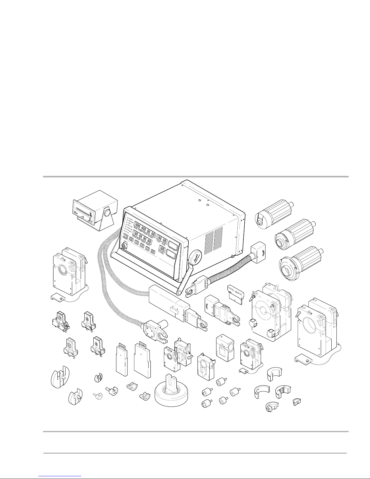
The Swagelok Welding System (SWS) is a versatile, portable and easy to use
orbital welding system. This section includes
D gas tungsten arc welding
D system components
D overview of SWS operation
D specifications.
2005 Swagelok Company, all rights reserved
September 2005
Figure 1-1 Swagelok Welding System
1-1

Introduction
CWS−D100−B Welding System
The purpose of this manual is to familiarize you with the SWS and to provide the
reference information needed to produce high-quality, repeatable welds.
While reading, you may encounter unfamiliar terminology. Some terms are common to
the welding industry and others particular to the SWS. Refer to Appendix A, Glossary,
if necessary.
Gas Tungsten Arc Welding
Principles of the GTAW Process
Gas Tungsten Arc Welding (GTAW) is a welding process that creates an arc between a
nonconsumable tungsten (or tungsten alloy) electrode and the work. The electrode is held
in a torch, rotor, or other device. GTAW uses a shielding gas, most commonly Argon, that
is delivered to the weld area. The shielding gas envelops the weld joint and electrode,
protecting both from contamination by the atmosphere.
The electric arc which creates the weld is produced by the passage of current through the
conductive ionized shielding gas. The arc is established between the tip of the electrode
and the work. Heat generated by the arc melts the base metal. Once the arc and weld
puddle are established, the electrode moves along the joint and the arc progressively melts
the joint surface. Filler wire, if used, is added to the leading edge of the weld puddle to
fill the joint.
GTAW provides precise control of heat input to the weld joint. For this reason, it is
preferred for joining thin gage metals and for making welds close to heat sensitive
components. The process offers advantages to many industries, ranging from the high
purity required in the semiconductor industry to autogenous manual welds of the
process industry.
The process can be used to weld almost all metals. GTAW can be used to weld all types of
joint geometries in tubing, pipe, or other structural shapes. It is particularly appropriate for
welding wall sections less than 3/8 in. (9,5 mm) thick.
GTAW Process Advantages
The GTAW process has the following advantages:
D produces superior quality welds
D allows excellent control of weld penetration
D welds almost all metals
D produces autogenous welds at high speeds
D allows precise control of the welding variables
D welds with or without filler metal
D eliminates spatter
1-2
2005 Swagelok Company, all rights reserved
September 2005

CWS−D100−B Welding System
Process Variables
The major process variables in GTAW are arc current, arc voltage, and travel speed.
D Arc Current − The current measured between the tungsten electrode and the work.
Generally stated, arc current controls the weld penetration.
Direct Current Electrode Negative (DCEN) is common for GTAW. It offers the
advantages of deep penetration and fast welding speeds because most of the heat
generated in the welding process is transferred to the work.
D Arc Voltage − The voltage measured between the tungsten electrode and the work.
Arc voltage is affected by the following:
D arc current
D shape of the tungsten electrode tip
D type and purity of shielding gas
Introduction
D arc length (distance between the electrode and the work)
Arc length is important with this process because it affects the width of the weld
puddle; puddle width is proportional to arc length. The desired arc length is as short
as possible.
D Travel Speed − The speed that the electrode moves over the work while welding.
Travel speed affects both the width and weld penetration of GTAW. Its effect on
width is more pronounced than on penetration. Increasing travel speed decreases the
width of the weld.
Travel speed generally is fixed in mechanized welding. Other variables such as
current or voltage are varied to maintain control of the weld.
2005 Swagelok Company, all rights reserved
September 2005
1-3
Introduction
CWS−D100−B Welding System
System Components
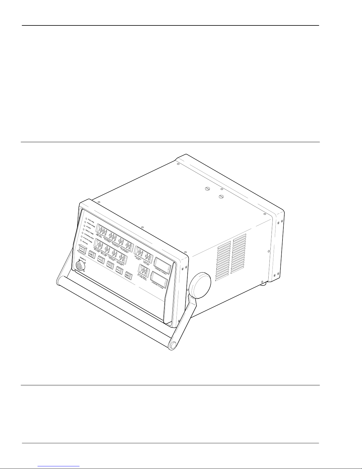
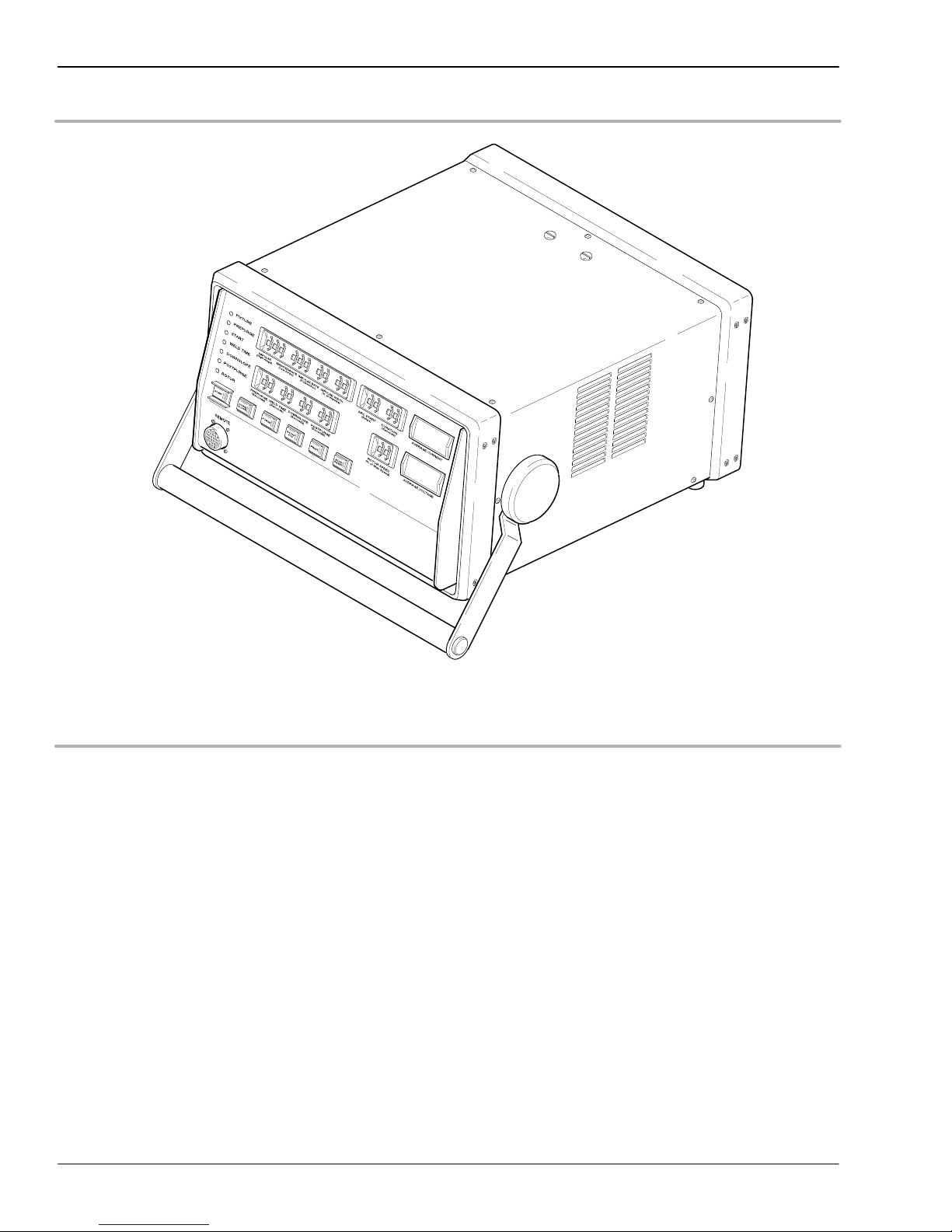
The SWS D100 Power Supply
The power supply features microcontroller electronics and closed-loop circuitry to
precisely control output current. Simplified controls and displays provide efficient
programming and monitoring of the welding process.
See Table 1-1 on page 1-9 for the power supply specifications.
Figure 1-2 SWS D100 Power Supply
1-4
2005 Swagelok Company, all rights reserved
September 2005
CWS−D100−B Welding System
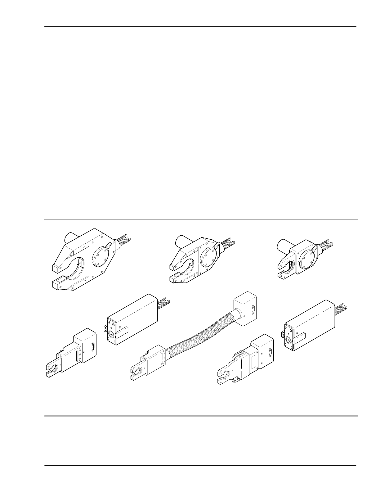
The Weld Head
The SWS weld heads deliver consistent, precise welds for outside diameters from 1/16 in.
to 2 in. (3 mm to 52 mm). There are six weld heads to choose from, depending on the size
of the work pieces. See Figure 1-3.
A dc motor in the weld head drives a rotor which carries the tungsten electrode around the
weld joint. Optical circuitry in the weld head sends precise feedback to the power supply
to control the speed of the rotor.
All moving parts in the weld head mount in low-friction devices to provide smooth,
consistent operation.
A spring-loaded, floating brush continuously contacts approximately one-third of the
circumference of the rotor at all times. This configuration ensures consistent, uniform
electrical conductance to the rotor and electrode.
Introduction
See Table 1-5 on page 1-10 for the weld head specifications.
Series Micro
Motor Module
Series 4 Micro
(Rigid)
Series 4 Micro
(Flexible)
Series 5Series 20 Series 10
Series Micro
Motor Module
Series 8 Micro
2005 Swagelok Company, all rights reserved
September 2005
Figure 1-3 Weld Heads
1-5
Introduction
CWS−D100−B Welding System
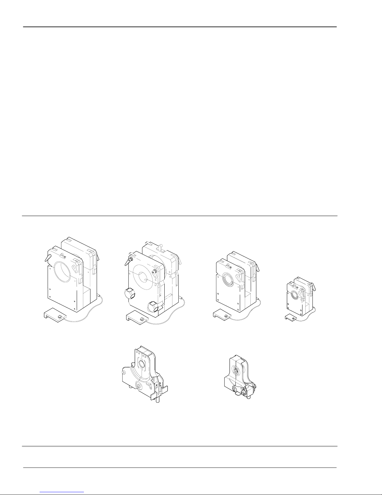
Fixture Blocks
The SWS fixture blocks accurately align and hold tubing, fittings, and valve bodies. The
modular design allows you to select different side plates and create the configuration
needed for the job.
The fixture block is separate from the weld head, allowing work pieces to be easily
aligned and fixtured before welding. The use of multiple fixture blocks offers
increased productivity.
Each fixture block is designed to accommodate a range of work piece sizes. A unique and
patented Universal Collet Insert (UCI) fits into the fixture block to match the diameter of
the work piece. The collet design firmly holds tubing and fittings that vary ± 0.005 in.
(0,13 mm) from nominal outside diameter. Collets are also available for thin wall pipe.
The collets exchange quickly, making the fixture block very adaptable to changing
work requirements. Tables 1-6, 1-7, and 1-8 list the available fixtures and collets.
Series 20-A Series 10
Series 20-B
Series 8
Series 4
Series 5
1-6
Figure 1-4 Standard Fixtures
2005 Swagelok Company, all rights reserved
September 2005

CWS−D100−B Welding System
Overview of SWS Operation
GTAW Orbital welding is a proven method for welding cylindrical shapes such as
tubes, fittings, and pipe. The SWS design makes the orbital welding process efficient
and effective.
The SWS provides an advanced method of autogenous GTAW. The system uses a fixture
block and associated weld head to provide precise fixturing of the work pieces. The
welding parameters are controlled by the SWS power supply and are programmed by
the operator.
Operating the SWS is uncomplicated. The work piece sizes define the fixture block
configuration, collets, and weld head to be used.
The fixture block quickly clamps onto the work pieces. The weld joint is centered in the
fixture block using a centering gage. Since the fixture block is not part of the weld head,
multiple fixture blocks can be used to maximize weld setup efficiency.
Introduction
The weld head cable assembly attaches quickly to the power supply. Setup of the weld
head is limited to the selection of an electrode and setting the arc gap. The arc gap setting
depends on the characteristics of the work pieces. A gage is provided with the weld head
to assist in setting the arc gap. After the arc gap is set, the weld head attaches to the fixture
block and is secured with a locking ring.
The power supply uses rotary switches for weld parameter control. See Figure 1-5. The
appropriate switch settings are generally defined by the work pieces to be welded and are
refined using test welds. The correct settings used for a specific job are developed into a
weld procedure guideline. The guideline is used to maintain repeatability and quality
control for subsequent jobs of the same type.
2005 Swagelok Company, all rights reserved
September 2005
1-7
Introduction
CWS−D100−B Welding System
Figure 1-5 SWS D100 Front Panel Controls
1-8
2005 Swagelok Company, all rights reserved
September 2005

CWS−D100−B Welding System
Specifications
Table 1-1 Power Supply
Model Supply Voltage* Service Amps Output Current (dc)
CWS-D100-1B 115 V (ac) 20 A 2 to 100 A
CWS-D100-1B 115 V (ac) 15 A 2 to 70 A
CWS-D100-2B 230 V (ac) 15 A 2 to 100 A
* 10% input voltage tolerance, frequency range 50 Hz to 60 Hz
Table 1-2 Duty Cycle
Model 6.25 % 60 % 100 %
CWS-D100-1B 100 Amps
14 Volts
CWS-D100-2B 100 Amps
14 Volts
32.3 Amps
11.3 Volts
32.3 Amps
11.3 Volts
25 Amps
11 Volts
25 Amps
11 Volts
Introduction
Duty cycle is the ratio of time the power supply can weld to the time the power supply
must remain idle to cool. The 10 minute cycle is a recognized welding industry standard.
It represents the maximum weld time allowed, with the balance of the 10 minute cycle
required for cooling.
Table 1-3 10 Minute Cycle Times
Maximum Weld TIme
Duty Cycle Rating
30 % 3 7
60 % 6 4
100 % 10 0
(Minutes)
Required Idle Time
(Minutes)
Continually exceeding the duty cycle may activate an internal thermal protector that will
disable the power supply and display message code 50. Refer to pages 3-13 and 3-15.
Table 1-4 Power Supply Dimensions and Weight
Model Dimensions (overall) Weight
CWS-D100-1B 15 1/2 in. (39 cm) wide
20 in. (51 cm) deep
9 in. (23 cm) high (without handle)
CWS-D100-2B 15 1/2 in. (39 cm) wide
20 in. (51 cm) deep
9 in. (23 cm) high (without handle)
42 lbs (19 kg)
45 lbs (20.4 kg)
2005 Swagelok Company, all rights reserved
September 2005
1-9

Introduction
CWS−D100−B Welding System
Table 1-5 Weld Heads
Series Model OD Capacity
4 Micro* CWS-4MRH-A
CWS-4MFH-A
8 Micro* CWS-8MRH 1/4 to 1/2 in.
5 CWS-5H-B 1/8 to 5/8 in.
10 CWS-10H-A 1/4 to 1 in.
20 SWS-20H-B** 1/2 to 2 in.
* Requires CWS-M-MTR-A motor module
** Requires SWS-20TFB-A
1/16 to 1/4 in.
(3 to 6 mm)
(6 to 12 mm)
(3 to 16 mm)
(6 to 25 mm)
(12 to 52 mm)
Table 1-6 Standard Fixture Blocks
Minimum Weld
Model OD Capacity
CWS-4MFA-** 1/16 to 1/4 in.
(3 to 6 mm)
SWS-8MFA-** 1/4 to 1/2 in.
(6 to 12 mm)
CWS-5TFB 1/8 to 5/8 in.
(3 to 16 mm)
CWS-10TFB 1/4 to 1 in.
(6 to 25 mm)
CWS-20TFB 1/2 to 2 in.
(12 to 52 mm)
SWS-20TFB-A 1/2 to 2 in.
(12 to 52 mm)
** Designates size in 1/16ths or mm; 4MFA- includes sizes 01, 02, 04, 3
mm, and 6 mm. 8MF- includes sizes 04, 06, 08, 6 mm, 8 mm, 10 mm,
and 12 mm
Extension Length
1/4 in. (6 mm)
1/4 in. (6 mm)
3/4 in. (19 mm)
3/4 in. (19 mm)
(recessed)
15/16 in. (24 mm)
(no recess)
1 3/8 in. (35 mm)
1.45 in. (37 mm)
1-10
2005 Swagelok Company, all rights reserved
September 2005
 Loading...