

Page 1
Air-Actuated Hydraulic
Swaging Unit (AHSU)
Setup and Operating Instructions
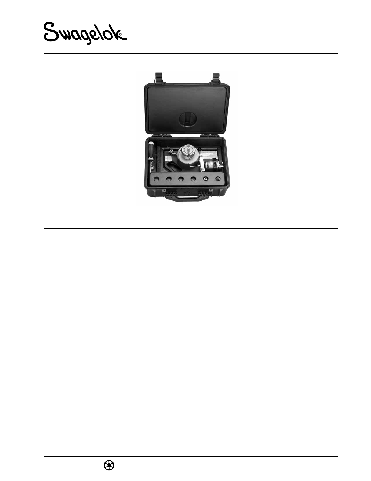
AHSU with base
Definitions
Statements and symbols are used in this document
to identify safety concerns. Read the definitions
below before setting up and operating the AHSU.
Caution: Statements that identify conditions or
practices that could result in damage
to the equipment or other property.
CAUTION!
Indicates cautionary information.
Warning: Statements that identify conditions or
practices that could result in personal
injury or loss of life.
WARNING!
EYE PROTECTION
Eye protection must be worn while
operating or working near the AHSU.
READ AND UNDERSTAND THESE INSTRUCTIONS BEFORE USING THE AHSU.
MS-12-38
Revision 2 10-03-CP
Page 2
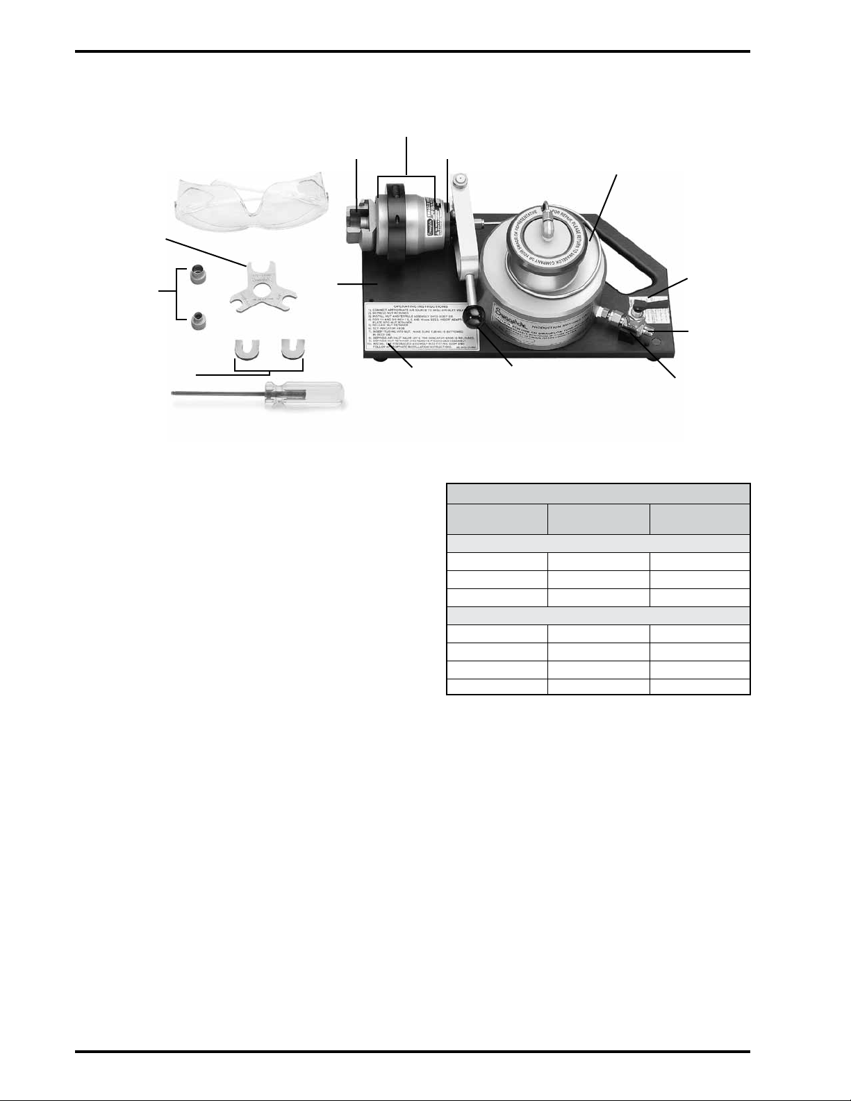
Components (Unit with Die Heads and Base)
Hydraulic housing
Nut retainer
Safety glasses
Gap
inspection
gauge
Die heads
Adapter plates
Hex key
Base
Safety Precautions
Use safety glasses when setting up and
operating the AHSU.
Do not tamper with or alter any
components of the AHSU.
Return the AHSU to your independent
Swagelok sales and service representative
if any signs of hydraulic fluid leakage or
malfunction occur.
Indicator knob
Air pump
Air input
decal
Air input
Operating
instructions
3. Select the proper size die head (reference the
size marked on each die head).
Indicator knob
set lever
Required Air Inlet Working Pressure, psig (bar)
Size
400 40 (2.8) 35 (2.4)
600 60 (4.2) 35 (2.4)
810 70 (4.9) 45 (3.1)
6M0 40 (2.8) 35 (2.4)
8M0 50 (3.5) 35 (2.4)
10M0 60 (4.2) 40 (2.8)
12M0 70 (4.9) 45 (3.1)
Stainless Steel or
Steel Tubing
Fractional Series
Metric Series
Air inlet
valve
Brass or Soft
Copper Tubing
Setup
1. Connect the appropriate air source to the AHSU
air inlet valve.
2. Adjust the source pressure to the value shown in
the table or on the air input decal for the tubing
material and size.
Air inlet pressure should be limited to less
than 90 psig (6.2 bar). If the inlet pressure
exceeds 90 psig, there is a pressure relief
valve in the unit that will activate.
2
4. Remove the screw located in the bore of the
die head previously installed in the hydraulic
housing by turning counter clockwise with the
hex key.
5. Depress the nut retainer to remove the die head.
6. Depress the nut retainer and install the selected
die head. Tighten the shaft screw sufficiently to
keep the die tight, being careful not to break the
screw by overtightening it.
7. For 1/4 and 3/8 in. and 6, 8, and 10 mm sizes,
insert the appropriate adapter plate into the nut
retainer. Refer to the mark on the plate for size
information.
MS-12-38
Revision 2 10-03-CP
Page 3

Operation
1. Install Swagelok nut and ferrules onto the die
head in order and orientation shown.
Note: The front edge of the nut should line up
with the groove on the outside of the die head.
Gauging Instructions
Use of the Swagelok AHSU gap inspection gauge
assures the installer or inspector that the fitting has
been sufficiently tightened.
Position the Swagelok gap inspection gauge
adjacent to the gap between the nut and body hex:
■ If the gauge will not enter the gap, the fitting is
sufficiently tightened.
■ If the gauge will enter the gap, additional
tightening is required.
Nut
2. Set the indicator knob by pivoting the indicator
knob set lever until the knob snaps into position
and is flush with the hydraulic housing.
3. Insert the tubing into the nut, make sure that
the tubing rests firmly on the shoulder of the die
head.
4. Hold the tubing firmly in the die head and
depress the air inlet valve handle for 3 seconds
after the indicator knob is released. The ferrules
have now been preswaged onto the tubing.
5. Release the air inlet valve handle.
6. Depress the nut retainer to remove the
preswaged assembly.
7. Install the preswaged assembly into the fitting
body. Turn the nut onto the fitting body until it
is finger-tight. Hold the fitting body stable and
tighten the nut 1/2 turn with a wrench.
Back
ferrule
Front
ferrule
Die
head
MS-12-38
Revision 2 10-03-CP
3
Page 4

Troubleshooting
Tubing is difficult to remove
from the AHSU after
preswaging.
Symptom Causes Corrections
Gently rock the tubing back
and forth to remove it.
Tubing wall may be below
recommended minimum wall
thickness.
Use tubing that is thicker than
the minimum recommended
wall thickness.
Do not rotate tubing.
The indicator knob does not
release.
Oil is leaking from unit.
The front edge of the
Swagelok nut does not line
up with the groove on the
outside of die head.
The unit fails to swage
sufficiently as indicated by
the gap inspection gauge
after assembly.
Improper inlet pressure being
used for tubing material and
size.
Improper die head being
used.
The ferrules are not oriented
properly.
The working pressure is too
low.
Adjust inlet pressure to the
correct value for the tubing
size and material.
Return the unit to your
independent Swagelok sales
and service representative.
Use the proper die head.
Place the ferrules in proper
orientation.
Verify the working air pressure
is set to the appropriate
pressure recommended on
the air input decal.
Do not swage a tube
more than once.
www.swagelok.com
4
Warranty Information
Swagelok products are backed by The Swagelok Limited
Lifetime Warranty. For a copy, visit swagelok.com or contact
your authorized Swagelok representative.
Swagelok—TM Swagelok Company
© 2002 Swagelok Company
Printed in U.S.A
Revision 2 10-03-CP
MS-12-38
 Loading...