

Page 1
Swadling Brassware, Churchward Road, Yate, Bristol, BS37 5PL
Telephone: 02392 255536 Email: [email protected]
SB0309 04/18
Invincible Double controlled outlet concealed valve
Installation manual
7209
7200
720
0
7209
Before disposing of the carton and commencing installation, please check all parts against the parts list on
back cover. Please contact us immediately if any parts are missing or damaged.
Page 2

IMPORTANT
Condition of use for type 2 valve High Pressure Low Pressure
Maximum static pressure 10 Bar 10 Bar
Flow pressure Hot and Cold 0.5 to 5.0 Bar 0.1 to 1 Bar
Hot Supply Temperature 55 to 65 °C 55 to 65 °C
Cold Supply Temperature Equal to or less than 25 °C Equal to or less than 25 °C
Valves operating outside these conditions cannot be guaranteed by the Scheme to operate as Type 2 valves.
For Dynamic ow pressures above 5 bar t pressure reducers.
Maximum Dynamic ow pressure ratio between hot & cold inlet supplies = 5:1
Optimum performance is achieved when hot and cold inlet pressures are nominally balanced to within 10% of each
other.
e shower mixer can accept temporary elevated temperatures to 85°C without damage.
Hot water storage temperatures should be maintained between 60-65°C.
Recommended outlet temperatures
44°C for bath ll see notes below
41°C for showers
41°C for washbasins
38°C for bidets
Mixed water temperatures must never exceed 46°C. e maximum mixed water temperature can be 2°C above
the recommended maximum set outlet temperatures.
Please read complete installation instructions before tting.
Specication. TMV2 valve for use with High and Low Pressure
Note:
46°C is the maximum mixed water for a bath tap. e maximum temperature takes account of the allowable
temperature tolerances inherent in thermostatic mixing valves and temperature losses in metal baths. It is not a
safe bathing temperature for adults or children.
e British Burns Association recommends 37 to 37.5°C as a comfortable bathing temperature for children. In
premises covered by Care Standards Act 2000, the maximum mixed water outlet temperature is 43°C.
e thermostatic mixing valve must be installed in such a position that maintenance of the TMV and its valves
and the commissioning and testing of the TMV can be undertaken.
SEE SETTING TEMPERATURE - Commissioning notes.
e valve is suitable for all water systems including Gravity fed, Pumped Systems, Combination Boilers,
Condensing Boilers, Mains Pressure fed Systems. However if used in low pressure gravity fed installations to
maximize ow rates use 22mm pipework reducing to 15mm close to the inlets for the HOT and COLD supplies.
Fit isolation valves as close as is practicable to both the HOT and COLD inlet supplies.
Page 3
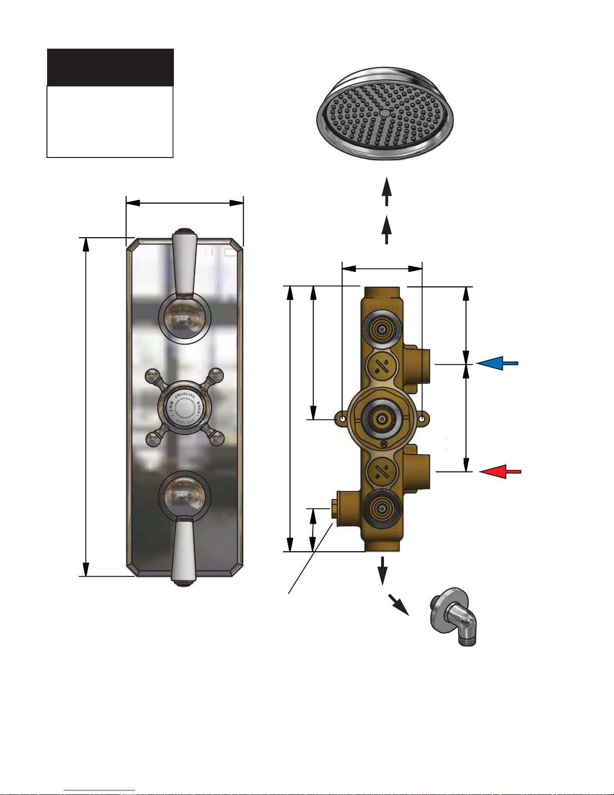
DIMENSIONS
CONFIGURATION
MAX Pressure =
5.0 BAR
Fit Pressure reducing
Valves above 5.0 BAR
Dimensions are approximate due to nature of materials used
2
3
5
80
80
250
7
5
1
0
0
1
2
5
2
2
0
75
BLANKING PLUG
OPTIONAL AUXILIARY
OUTLET FOR ON/OFF VALVE
220
125
100
75
75
40
Page 4
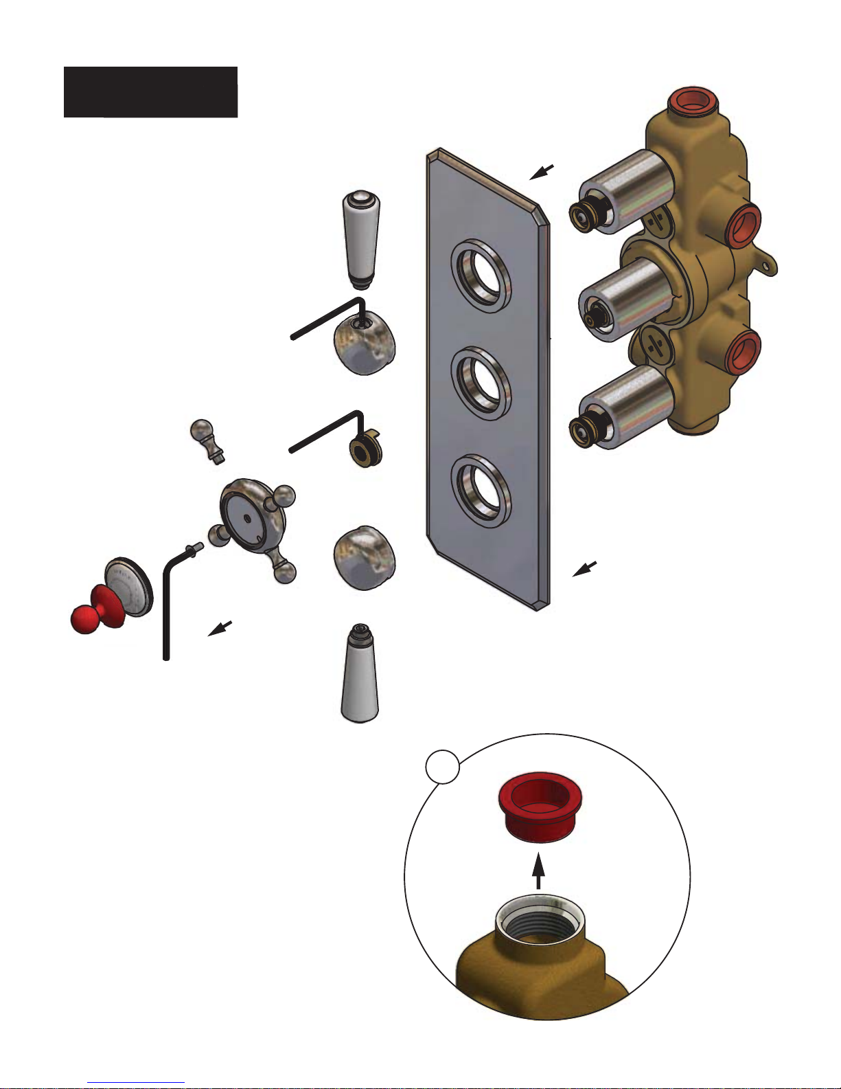
PREPARATION
x 4
1
REPARATIO
N
2mm
2.5mm
2mm
Page 5
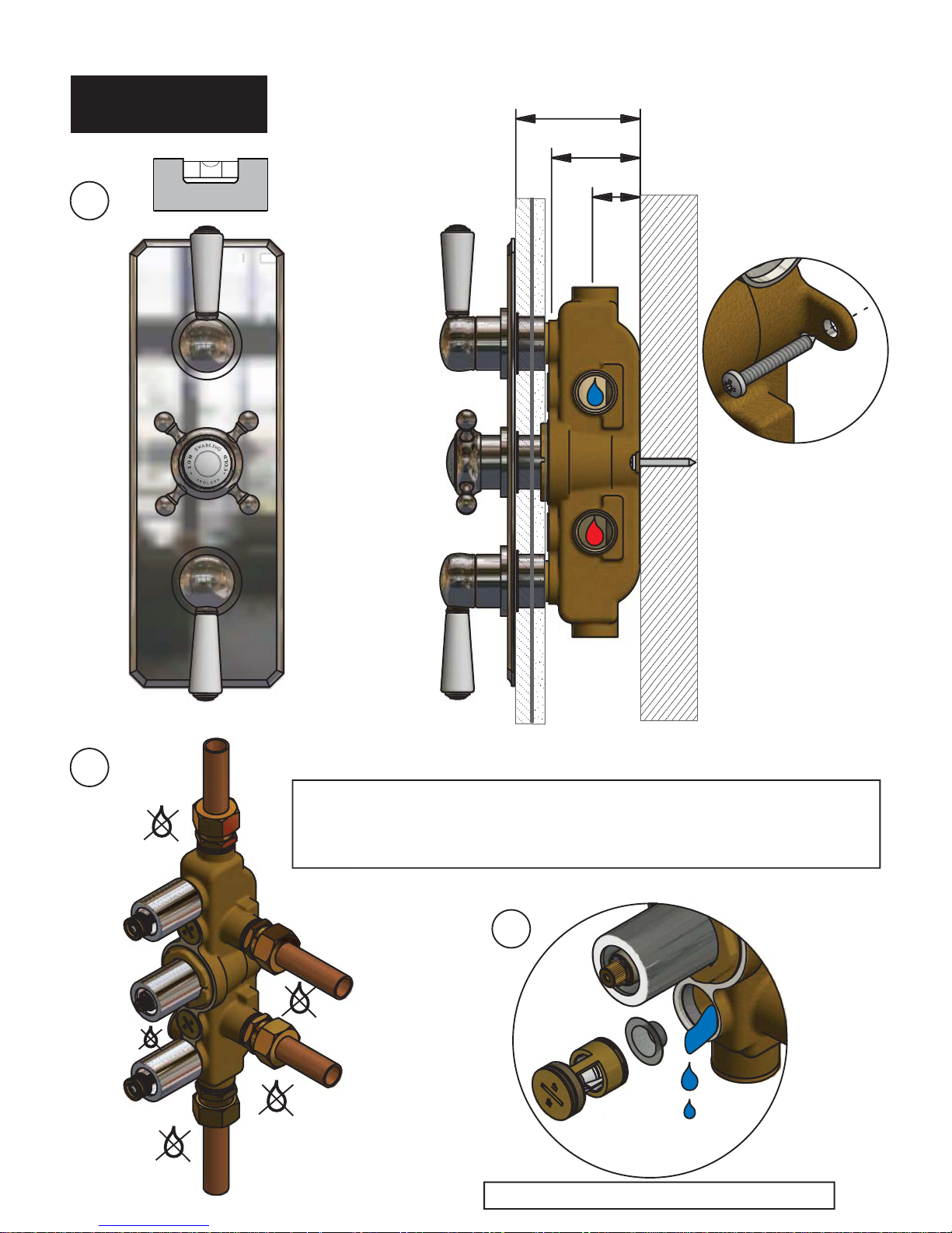
Remove hot and cold return valves and ush out
6
5
32
MIN 75 - MAX 105
2
+/- 0mm
e Inlets and outlets are 3/4” BSP (Parallel) reads. DO NOT USE TAPER
THREADED ADAPTERS OR OVERTIGHTEN ADAPTERS
Use appropriate thread sealer. Oil-based non-setting jointing compounds should not be
used!
MOUNTING &
PLUMBING
3
4
x 2x
2
x 2x
2
Page 6
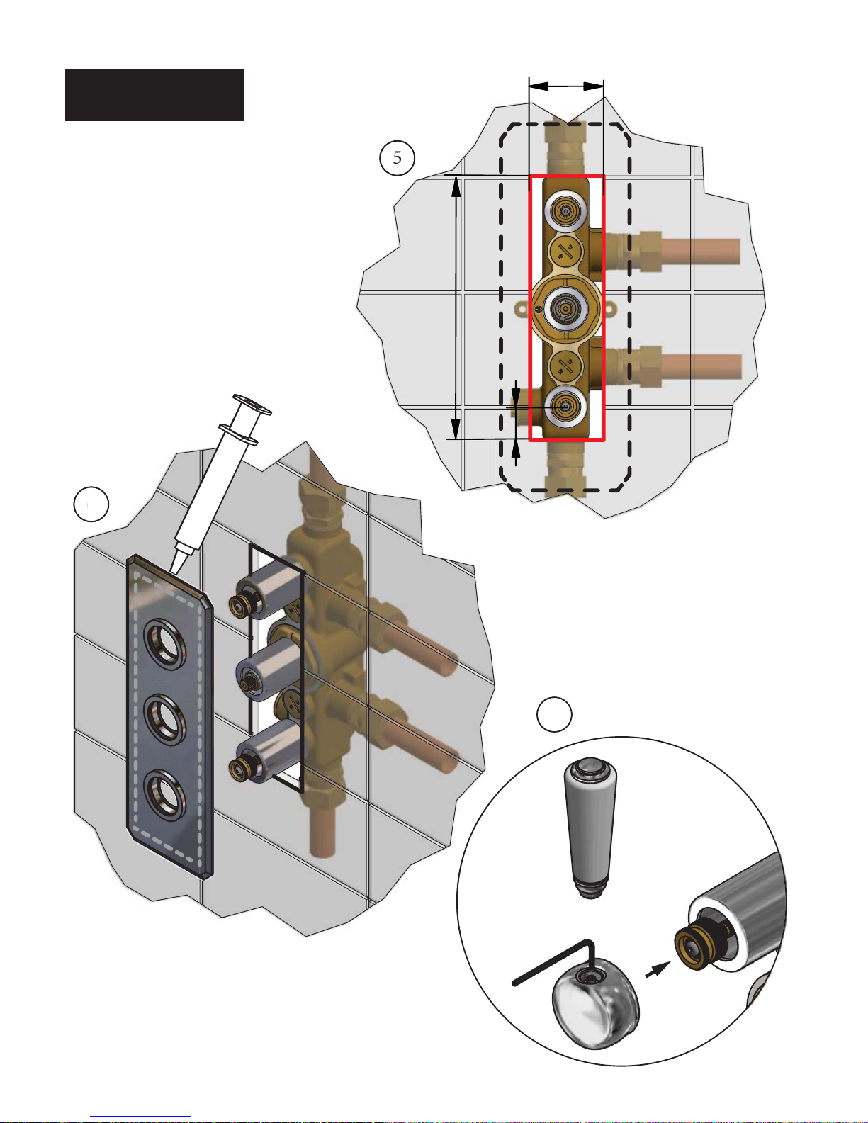
TILING
5
6
7
2mm
62
230
30
SILICONE
Page 7
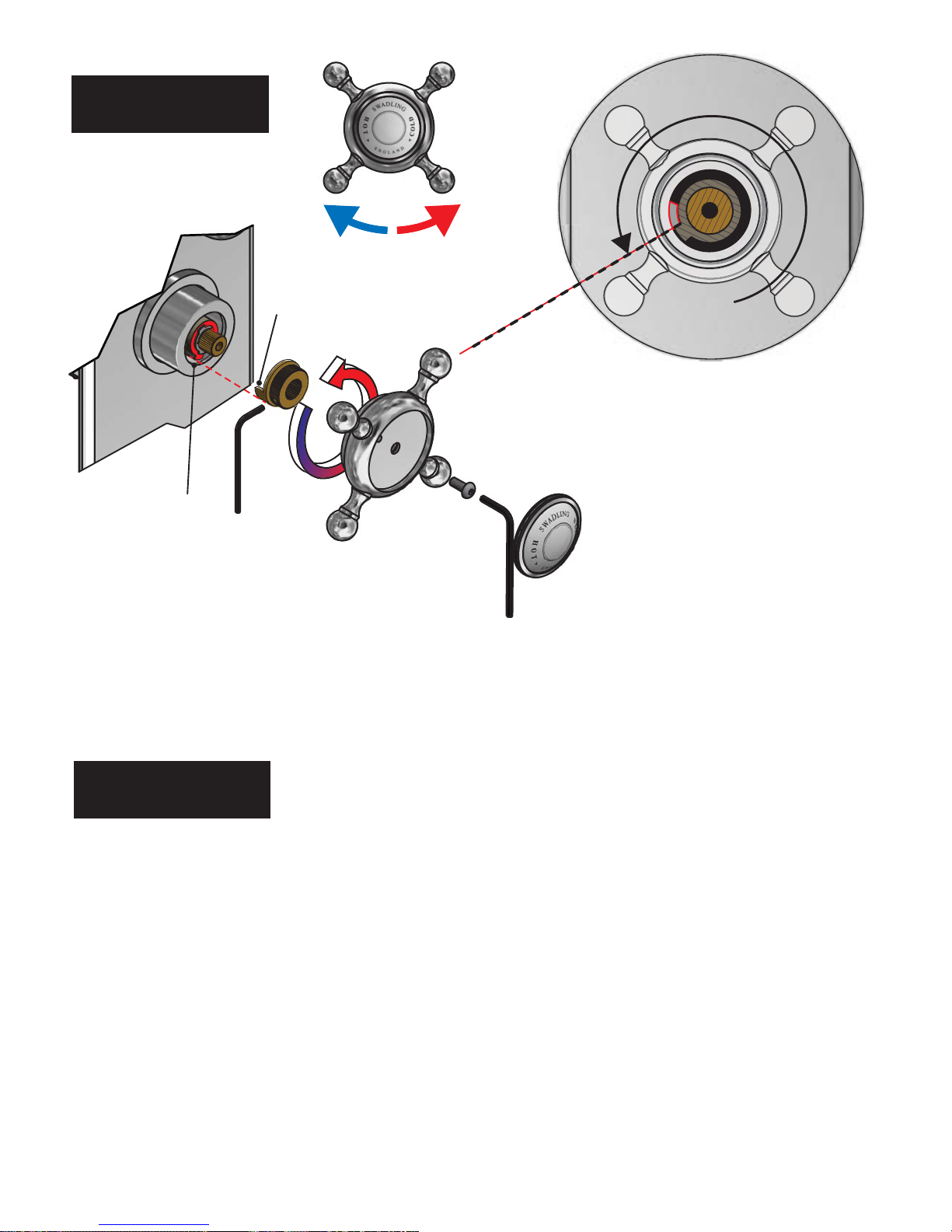
1. Assemble the Temperature handle to the ermostatic cartridge.
2. Using the handle rotate anti-clockwise until the Handle temperature stop meets the Cartridge temperature stop and will
not turn anymore anti-clockwise. is is the maximum hot water temperature - e maximum temperature should not
exceed 41°c.
3. To adjust the maximum temperature - Remove handle, re-position the Handle temperature stop by rotating the handle,
re-t handle and turn to stop position, re-test.
If using for a Bath ller see IMPORTANT page for advised maximum temperatures.
Commissioning notes for ermostatic Mixing Valves, please check the following
(a) e designation of the ermostatic Mixing Valve matches the application. (b) e supply pressures are within the valve
operating range.(c) e supply temperatures are within the valve operating range. (d) Isolating valves are tted.
If all these conditions are met set the temperature as per installation instructions.
It is a requirement that all TMV2 approved valves shall be veried against the original set temperature results once a
year. When commissioning/testing is due the following performance checks should be done.
Measure the mixed water temperature at the outlet. Carry out the cold water supply isolation test by isolating the cold
water supply to the TMV, wait for ve seconds if water is still owing check that the temperature is below 46°C. If there
is no signicant change to the set outlet temperature (+/- 2°C or less change from the original settings) and the fail-safe
shut o is functioning, then the valve is working correctly and no further service work is required.
Notes; If there is a residual ow during the commissioning or the annual verication (cold water supply isolation test)
then this is acceptable providing the temperature of the water seeping from the valve is no more than 2°C above the
designated maximum mixed water outlet temperature setting of the valve. Temperature should be taken at normal ow
rate aer allowing for the system to stabilise. e sensing part of the readings thermometer probe must be fully
submerged in the water that is to be tested. Any TMV that has been adjusted or serviced must be re-commissioned and
re-tested in accordance with the installation instructions. e installation of the thermostatic mixing valve must
comply with the requirements of the Water Supply (Water Fittings) Regulations 1999.
SETTING THE
TEMPERATURE
HANDLE
TEMPERATURE
STOP
CARTRIDGE
TEMPERATURE
STOP
HOT STOP
COMMISSIONING
& MAINTENANCE
Page 8
.
.
IMPORTANT. Before commencing maintenance on the shower isolate the hot and cold supplies.
When maintenance is complete ensure the shower valve is checked and fully commissioned before use.
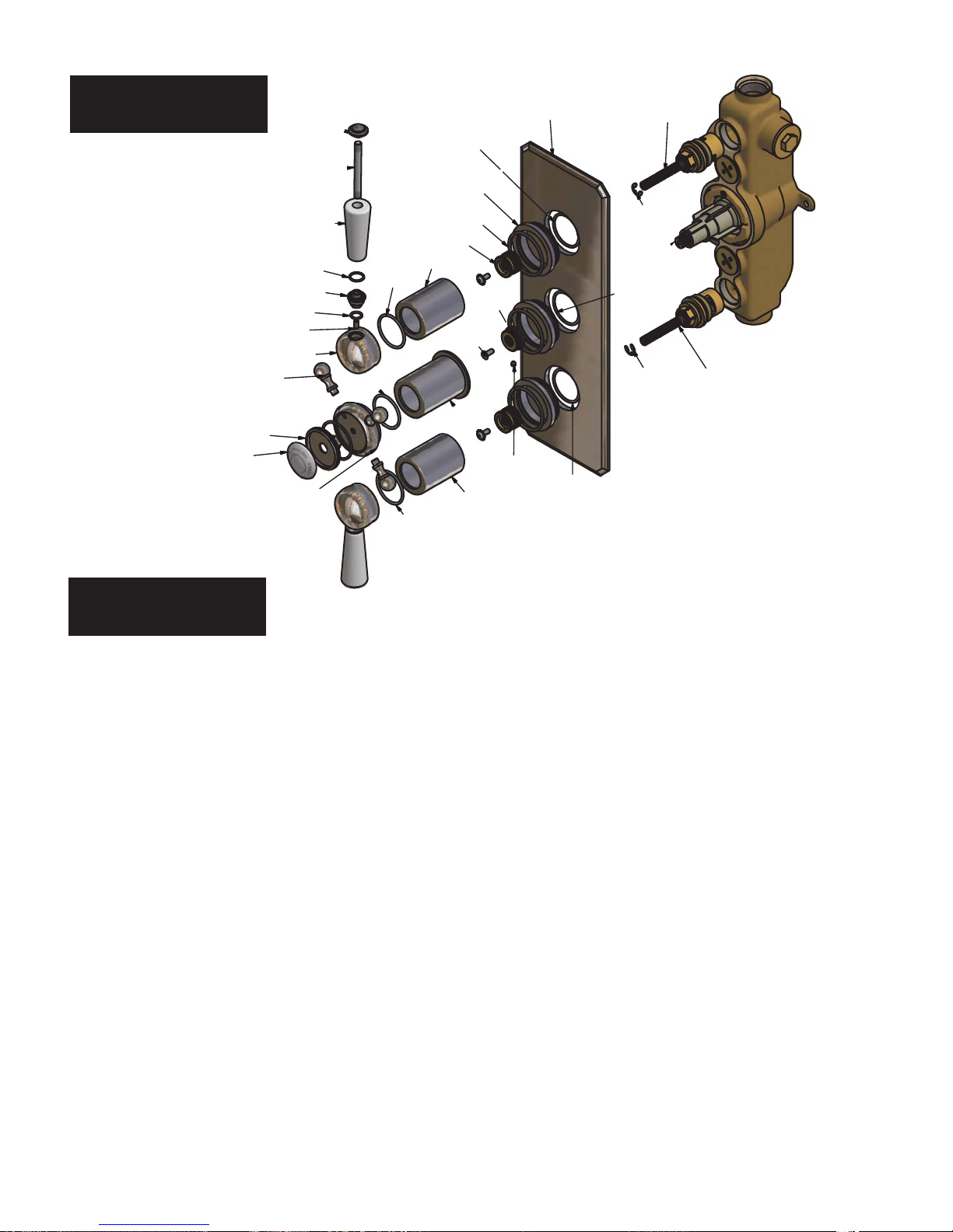
PARTS LIST
1. Fault, Aer installation shower only runs Hot or Cold and will not mix.
Hot & Cold supplies are plumbed the wrong way around. Remove the thermostatic cartridge, undo the 52mm AF clamp nut
and pull the cartridge out (use the temperature knob to aid removal) reinstall the thermostatic cartridge with the lug pointing
away from the hot and cold inlets.
2. Fault, Shower will not run hot enough when rst installed.
Maximum temperature needs adjusting, see SETTING THE TEMPERATURE
3. Fault, Cold water tracking through the valve into the hot water system. Check and clean the non return valve cartridges
and gauze lters located under the non return valves. (See illustration on Mounting and plumbing stage).
4. Fault, Shower will not run hot when rst installed. See SETTING THE TEMPERATURE. Check hot water supply from
boiler is at specied temperature. See IMPORTANT.
5. Fault, Shower only runs cold or lukewarm when rst installed. ermostatic cartridge may have debris trapped in the
cold side. Clean thermostatic cartridge.
6. Fault, Very low ow or no ow (gravity). Check Hot & Cold feeds (the valve will shut down if either Hot or Cold supply
fails). Ensure the correct operation of any ow switches (in pumped applications).
7. Fault, No ow or very low ow (gravity fed installations). Very low pressure or blocked lters or pipe work.
8. Fault, No ow or very low ow (pump fed installations). Flow rate may be insucient to activate booster pump ow
switches, check pump requirements.
9. Fault, Vibration or hammering. Dynamic water pressure ratio between hot and cold inlets greater than 5:1 maximum. For
optimum performance the inlet pressures should be balanced to within 10% of each other. Check for loose pipe work.
10. Fault, Shower will not turn o, turning ow control has no eect. Shower may be plumbed to wrong outlet.
TROUBLE SHOOTING
SB0070
SB0070
SB0082
1178 AF
1178 AF
1595 AF
1595 AF
1595 AF
SB1031
1912
SB0035
SB0103
1298 A SILVER
1397 A SILVER
SB0111
SB0073
SB0112
SB0111
SB1035
SB0048
SB1422
1604 AF
SB0086
SB1936
1360 A SILVER
SB0036
SB1029
SB0234
SB0087
SB0169
SB0073
SB0073
SB1401
 Loading...