

Page 1
RF Distribution
Amplifiers
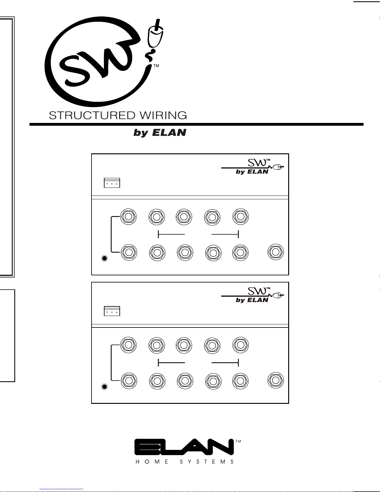
VDA38B
VDA38H
ir out
gnd
+15vdc
B
(pwr)
Mod input
A
ir out
gnd
+15vdc
B
(pwr)
Mod input
3 X 8 Bi-Directional Video Distribution Amplifier
TV output
3 X 8 High Headroom Video Distribution Amplifier
TV output
VDA38B
CATV
VDA38H
CATV
A
Page 2
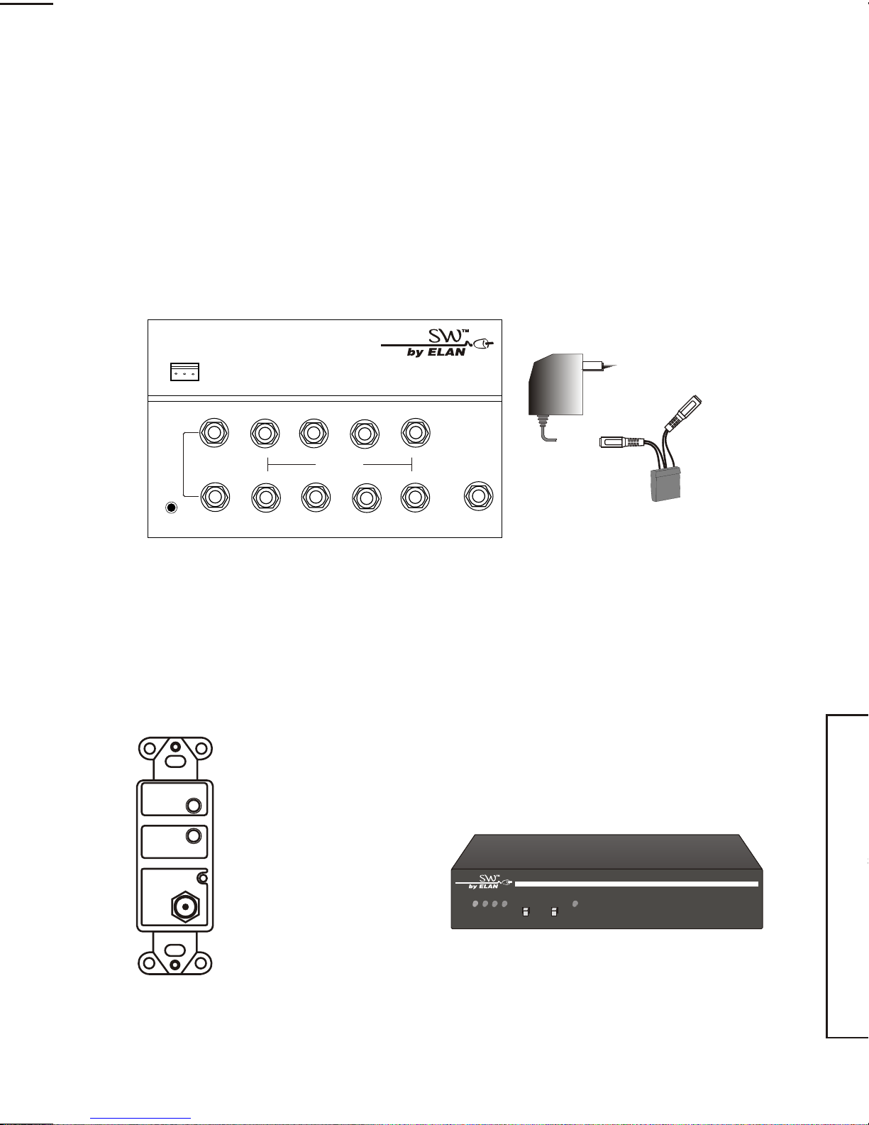
Models VDA38B & VDA38H Video Distribution Amplifiers
Things To Watch For:
The VDA38B or VDA38H is the heart of any RF distribution system. Each is a 3–IN
by 8–OUT RF distribution amplifier that connects as many as 8 televisions to cable
or antenna while maintaining optimum signal strength to all TVs. Each also has the
capability of sending IR down each coax run for control of local TVs or video source
components.
Contents:
VDA38
Power Supply (15VDC @ 300mA)
Power/IR adaptor
ir out
gnd
+15vdc
VDA38B
CATV
B
(pwr)
Mod input
A
3 X 8 Bi-Directional Video Distribution Amplifier
TV output
Herringbone interference on modulator channel (diagonal lines): You may have
chosen a channel number that is not completely vacant. Distant UHF stations may
not be watchable, but will cause interference if you try to create a new channel at
the same frequency. Also, cable companies often have extra signals where there
should be none. Try moving the modulator channel to another number. You may
have to add a low pass filter to remove the cable company noise. If the filter does
not work, try adding a DC-block to remove common mode interference.
Herringbone interference on many channels, including modulator channels
(disappears when you remove the CATV/antenna feed): The RF amplifier can be
overloaded by abnormally strong signals. Often, you can cure the problem with a
simple attenuator. Use a variable attenuator and try to find a signal level where the
interference just disappears. Sometimes, the problem is one station is far stronger
than the rest. In this case, attenuating all of the signals with a simple attenuator
will cause the desired stations to be weak (snowy). You must reduce the strength
of the only offending station. A common FM trap will help if the problem is a nearby
FM tower. If the problem is a nearby TV station, often the station management can
provide suitable filters.
We recommend using only RG-6 coax when wiring a house for RF distribution.
Why? Although good RG-59 has only slightly more loss than RG-6, it is harder to
find a good RG-59 with wide bandwidth. RG-6 is a little more expensive and a little
harder to run (it is thicker). But you will avoid surprises if you stick to RG-6.
Model Differences:
The VDA38H is for antenna or uni-directional cable systems and has the highest
headroom of any coax panel available in the market.
PRINTER'S INSTRUCTIONS:
The VDA38B is for bi-directional cable systems providing a 5-42MHz back channel
for cable modems or interactive set-top boxes.
Accessories:
Specifications:
Gain:
CATV/Antenna port to output
TARGET
LED
EMITTER
TO
TV
POWER
CXIRWP
COAX/IR wall plate
breaks out the IR signal
from the coax cable.
Emitter jack for source
control. Power supply
included.
Powers the VDA38
remotely and has a builtin IR wall plate.
(fits standard Decora)
MOD4000 4-Channel Digital Modulator
4-Channel Digital Modulator
A B C D
select program
IR
pll frequency control
MOD4000
Modulator input to output
Output to CATV (reverse)
Isolation:
Modulator input to CATV/Ant
Max CATV/Antenna input:
Power Supply: (included)
General:
Width x height x depth (in)
Shipping weight
INSTR,INSTL,VDA38B_H,OEM - LINEAR P/N: 222759 X2 - INK: BLACK - MATERIAL: 113 GSM WHITE PAPER COATED 2-SIDES (C2S) - SIZE: 8.500" X 11.000" - FOLDING: ALBUM FOLD, BINDING: SADDLE-STITCH - SCALE: 1-1 - IMAGE 2 OF 4
2
Page 3
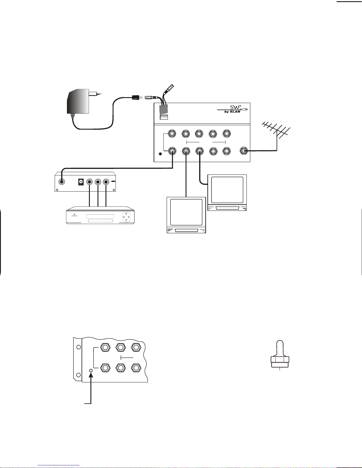
Typical Installation:
The VDA38 works like a zero-loss splitter. The signals you put on the
antenna/CATV input will appear on the outputs with about 3dB of gain.
ir out
gnd
Modulator may be
connected to A or B input.
+15vdc
B
(pwr)
A
Mod input
3 X 8 Bi-Directional Video Distribution Amplifier
TV output
VDA38B
CATV
CATV or
Antenna
POWER
OUTPUT
LOOP
AUDIOAUDIO
VIDEO
recommended
for all runs
Up to 8 TVs
DVD, VCR
or Satellite
Circuit Breaker:
The VDA38 has a built-in circuit breaker. If the power LED is not lit, reset the circuit
breaker by disconnecting and reconnecting the power supply. If the system does
not reset, look for an installation error.
VDA38
RG-6 coax
B
(pwr)
Mod input
A
TV out
Note: Connecting a 75ohm
terminator directly to an
output of a VDA38 will
cause the circuit breaker to
trip.
Power LED
3
Page 4

IR Repeating System:
IR Troubleshooting (continued)
With VDA38 you can also control your video components from any room in the
house.
Any or all 8 outputs of a VDA38 may be connected to a CXIRWP wall plate. The
CXIRWP breaks out the IR signal from the coaxial cable and features an input jack
for an IR receiver and an output jack for an IR emitter (see the CXIRWP installation
manual for further details).
If the VDA38 happens to be located in the media center, an IR emitter may be
connected directly to the VDA38 as shown below.
IR signals are
repeated at media
center controlling a
video product.
ELAN
IR emitter
CXIRWP
wall plate
Media
Center
ELAN IR emitter
VDA38B
Bedroom
CATV
B
(pwr)
Mod input
A
3 X 8 Bi-Directional Video Distribution Amplifier
TV output
2) First disconnect the coax cables from all of the television output jacks. Find the
source of the noise by re-connecting cables one at a time until the IR light glows.
This identifies that coax as a noise source. Connect this noisy coax only for the next
steps. Remember that there could be more than one source of noise, so you may
need to repeat the following steps for each coax. Now step 3 will determine which
type of noise problem you have.
Shade the target
Move the target
If the system trips the circuit breakers (IR systems only)
Using DC blocks. All output ports must be connected to a CXIRWP wall plate OR a
DC block. If DC blocks are not used, the internal circuit breaker may trip to protect
the system. (An output port that is not used will not trip the system and requires no
DC block.)
PRINTER'S INSTRUCTIONS:
ELAN
IR receiver
TV with IR receiver connected to a
CXIRWP wall plate.
DC Block
IR Troubleshooting
1) If IR light glows steadily, there is
noise entering the system.
4-Channel Digital Modulator
pll frequency control
A B C D
select program
IR
ir out
gnd
+15vdc
3 X 8 Bi-Directional Video Distribution Amplifier
B
(pwr)
Mod input
A
MOD4000
MOD4000
modulator
TV output
VDA38B
CATV
TARGET
LED
EMITTER
POWERPOWER
TO
TV
TV set
is ON
1) Hook from the top
2) Swing into place
3) Push button to lock
INSTR,INSTL,VDA38B_H,OEM - LINEAR P/N: 222759 X2 - INK: BLACK - MATERIAL: 113 GSM WHITE PAPER COATED 2-SIDES (C2S) - SIZE: 8.500" X 11.000" - FOLDING: ALBUM FOLD, BINDING: SADDLE-STITCH - SCALE: 1-1 - IMAGE 4 OF 4
4
Page 5

IR Troubleshooting (continued)
2) First disconnect the coax cables from all of the television output jacks. Find the
source of the noise by re-connecting cables one at a time until the IR light glows.
This identifies that coax as a noise source. Connect this noisy coax only for the next
steps. Remember that there could be more than one source of noise, so you may
need to repeat the following steps for each coax. Now step 3 will determine which
type of noise problem you have.
3a) Optical noise. Cover the target with a towel. If the IR
lights stops blinking, you have optical noise. The target
may be pointed at a window, a fluorescent light or a
Shade the target
TV set
is ON
plasma TV. Reposition the target so it can’t “see” the
source of IR light. If the IR light still glows, proceed to the
next step.
3b) EMI noise: TV sets are sources of EMI, electromagnetic
interference. Move the target away from the TV and try to
reposition the target so the IR light stays off.
Move the target
TV set
is ON
If the system trips the circuit breakers (IR systems only)
Using DC blocks. All output ports must be connected to a CXIRWP wall plate OR a
DC block. If DC blocks are not used, the internal circuit breaker may trip to protect
the system. (An output port that is not used will not trip the system and requires no
DC block.)
ir out
gnd
+15vdc
(pwr)
A
3 X 8 Bi-Directional Video Distribution Amplifier
B
Mod input
TV output
VDA38B
CATV
Use a DC block on all
output ports that do not
connect to a CXIRWP wall
plate. (IR systems only)
DC Block
ELAN modules attach from the top
1) Hook from the top
2) Swing into place
3) Push button to lock
All ELAN modules are
grid compatible.
TM
TM
1
Ports
Telephone Expansion Hub (4 lines x 8 phones)
TelephonesExpansion
R
4
T
R
3
T
R
2
T
R
1
T
3
2
In
Out
5
Page 6

Expanding the VDA38:
Typical Installation:
You may connect up to 8 more VDA38s to the outputs of a master VDA38, for a total
of 64 TV outlets. The longest recommended coax run should not exceed 150’. That
is a total of the coax from master to slave and slave to TV.
Master VDA38
ir out
gnd
+15vdc
VDA38B
CATV
CATV or
B
(pwr)
Mod input
A
3 X 8 Bi-Directional Video Distribution Amplifier
TV output
Antenna
ir out
gnd
+15vdc
VDA38B
CATV
ir out
gnd
+15vdc
3 X 8 Bi-Directional Video Distribution Amplifier
VDA38B
B
(pwr)
Mod input
A
3 X 8 Bi-Directional Video Distribution Amplifier
TV output
The VDA38 works like a zero-loss splitter. The signals you put on the
antenna/CATV input will appear on the outputs with about 3dB of gain.
connected to A or B input.
OUTPUT
B
PRINTER'S INSTRUCTIONS:
Slave VDA38s
(pwr)
Mod input
A
TV output
CATV
Circuit Breaker:
The VDA38 has a built-in circuit breaker. If the power LED is not lit, reset the circuit
breaker by disconnecting and reconnecting the power supply. If the system does
not reset, look for an installation error.
Each VDA38 must be powered individually. Each slave VDA38 can have local
modulators and a zoned IR system for TVs connected to the eight outputs. Any
modulator signals injected into a slave VDA38 will be viewable only on the eight
TVs connected to it. Modulators connected to the master VDA38 will be viewable
on all TV outputs including slave VDA38s.
Power LED
INSTR,INSTL,VDA38B_H,OEM - LINEAR P/N: 222759 X2 - INK: BLACK - MATERIAL: 113 GSM WHITE PAPER COATED 2-SIDES (C2S) - SIZE: 8.500" X 11.000" - FOLDING: ALBUM FOLD, BINDING: SADDLE-STITCH - SCALE: 1-1 - IMAGE 3 OF 4
6
Page 7

Things To Watch For:
Herringbone interference on modulator channel (diagonal lines): You may have
chosen a channel number that is not completely vacant. Distant UHF stations may
not be watchable, but will cause interference if you try to create a new channel at
the same frequency. Also, cable companies often have extra signals where there
should be none. Try moving the modulator channel to another number. You may
have to add a low pass filter to remove the cable company noise. If the filter does
not work, try adding a DC-block to remove common mode interference.
Herringbone interference on many channels, including modulator channels
(disappears when you remove the CATV/antenna feed): The RF amplifier can be
overloaded by abnormally strong signals. Often, you can cure the problem with a
simple attenuator. Use a variable attenuator and try to find a signal level where the
interference just disappears. Sometimes, the problem is one station is far stronger
than the rest. In this case, attenuating all of the signals with a simple attenuator
will cause the desired stations to be weak (snowy). You must reduce the strength
of the only offending station. A common FM trap will help if the problem is a nearby
FM tower. If the problem is a nearby TV station, often the station management can
provide suitable filters.
We recommend using only RG-6 coax when wiring a house for RF distribution.
Why? Although good RG-59 has only slightly more loss than RG-6, it is harder to
find a good RG-59 with wide bandwidth. RG-6 is a little more expensive and a little
harder to run (it is thicker). But you will avoid surprises if you stick to RG-6.
MOD4000
10dB
5dB
0dB
min
Inexpensive variable
attenuator
15dB
20dB
max
Specifications:
Gain:
CATV/Antenna port to output
Modulator input to output
Output to CATV (reverse)
(5-42 MHz)
Isolation:
Modulator input to CATV/Ant
Max CATV/Antenna input:
Power Supply: (included)
General:
Width x height x depth (in)
Shipping weight
Inexpensive DC block
VDA38H
3 dB
-10 dB
n/a
>80 dB
5-1000 MHz
20 dBmV (+80 dBµV)
15 VDC @ 300 mA
6.5” x 1.25” x 4.5”
for RF
VDA38B
3 dB
-10 dB
-15 dB
>35 dB
54-1000 MHz fwd
5-42 MHz reverse
20 dB mV (+80 dBµV)
15 VDC @ 300 mA
4 lbs.
7
Page 8

Limited Warranty
ELAN HOME SYSTEMS, L.L.C. ("ELAN") warrants the VDA38B and VDA38H to be
free from defects in materials and workmanship for a period of 5 years from the
date of purchase. If within the applicable warranty period above purchaser
discovers such item was not as warranted above and promptly notifies ELAN in
writing, ELAN shall repair or replace the items at the company's option. This
warranty shall not apply (a) to equipment not manufactured by ELAN, (b) to
equipment which shall have been installed by other than an authorized ELAN
installer , (c) to installed equipment which is not installed to ELAN's specifications,
(d) to equipment which shall have been repaired or altered by other s than ELAN, (e)
to equipment which shall have been subjected to negligence, accident, or damage
by circumstances beyond ELAN's control, including, but not limited to, lightning,
flood, electrical surge, tornado, earthquake, or any other catastrophic events
beyond ELAN's control, or to improper operation, maintenance or storage, or to
other than normal use of service. With respect to equipment sold by, but not
manufactured by ELAN, the warranty obligations of ELAN shall in all respects
conform and be limited to the warranty actually extended to ELAN b y its supplier.
The foregoing warranties do not cover reimbursement for labor, transportation,
removal, installation, or other e xpenses which may be incurred in connection with
repair or replacement.
Except as may be expressly provided and authorized in writing by ELAN, ELAN
shall not be subject to any other obligations or liabilities whatsoever with respect
to equipment manufactured by ELAN or services rendered by ELAN.
THE FOREGOING WARRANTIES ARE EXCLUSIVE AND IN LIEU OF ALL OTHER
PRINTER'S INSTRUCTIONS:
FCC Requirements:
THIS PRODUCTS COMPLIES WITH FCC REQUIREMENTS. A SYSTEM USING
THIS DEVICE WILL COMPLY WITH FCC REQUIREMENTS. USE ONLY VIDEO
MODULATORS THAT COMPLY WITH PART 15 OF THE FCC RULES AND HAVE
A 25dBmV MAX OUTPUT LEVEL. FAILURE TO DO SO MAY VOID THE USER’S
AUTHORITY TO OPERATE THIS EQUIPMENT.
THE VDA38H IS SUITABLE FOR USE WITH AN ANTENNA OR WITH CATV
SYSTEMS.
THE VDA38B IS SUITABLE FOR USE WITH CATV SYSTEMS.
ELAN Home Systems
INSTR,INSTL,VDA38B_H,OEM - LINEAR P/N: 222759 X2 - INK: BLACK - MATERIAL: 113 GSM WHITE PAPER COATED 2-SIDES (C2S) - SIZE: 8.500" X 11.000" - FOLDING: ALBUM FOLD, BINDING: SADDLE-STITCH - SCALE: 1-1 - IMAGE 1 OF 4
222759 X2
 Loading...