


SVT-MF4 Outdoor Station G
User Manual
Please read this user manual prior to installing the system, and keep it well for future use.

CONTENTS
1.
Parts and Functions.............................................................................................. 1
2.
Terminal Descriptions .......................................................................................... 2
3.
Specifications....................................................................................................... 3
4.
Mounting ............................................................................................................... 3
5.
System Wiring and Connections ......................................................................... 5
5.1 SVT-4 System with one entrance .................................................................... 5
5.2 SVT-4 System with two entrances .................................................................. 6
6.
Cable Requirements ........................................................................................... 10
7. User Instructions . ............................................................................................... 11
5.3 SVT-4 Wiring Connection .............................................................................. 7
7.1 Visitor calls .................................................................................................... 11
7.2 Monitor .......................................................................................................... 12
7.3 Intercom ........................................................................................................ 13
4.1 Mounting without the Rain Guard..................................................................... 3
4.2 Mounting with the Rain Guard..........................................................................4
4.3 Mounting the Indoor Monitor............................................................................ 4
5.3.1 Indoor Station........................................................................................... 7
5.3.2
Outdoor Station........................................................................................ 7-8
8.
How to set up User Codes ................................................................................. 14-15
5.3.3 Electric door lock connection ................................................................... 9

-1-
1.Parts and Functions
3
# Description
1
2
LED lights
3
High resolution camera
4
Built-in speaker
5
Call button
Built-in microphone
# Description
1 Built-in microphone
2 Monitor button
3 Intercom button
4 Door unlock button
5 Talk button
6 TFT 7” color display
7 Built-in speaker
8 Talking/Ring volume
9 Brightness
10 Contrast
Status light.
Calling in: red light
Monitoring/Talking: blue light
6
Name plate
7
Fingerprint Scanner

-2-
2.Terminal Descriptions

-3-
160-165 cm
1 2
4.
Mounting
Hatch
Install into the wall
Screw hole
Screws
(fix with button
case)
3.Specifications
OUTDOOR STATION
Voltage: DC 14.5V
NO/NC/COM: Max. 14.5V 200mA
Lock Power Supply: Must be used according to lock.
Unlocking time: 01 - 99 seconds
Communication duration: 120s.
Communication
transmission: 2-way comm
unication
Working temperature: -4°F to 131°F / -20°C to +55°C
INDOOR MONITOR
Voltage
: DC 14.5V
Communication duration: 120s.
Communication
transmission
: 2-way comm
unication
Working temperature: 14°F to 131°F / -10°C to 55°C
4.1. MOUNTING WITHOUT THE RAIN GUARD

-4-
Screw
anchors
Screws
Screws
(fix with rain cover)
Rain
cover
Wall
hole
4.2. MOUNTING WITH THE RAIN GUARD
4.3. MOUNTING THE INDOOR MONITOR

-5-
5.1. SVT-MF4 SYSTEM WITH ONE ENTRANCE
System Wiring and Connections5.
-6-
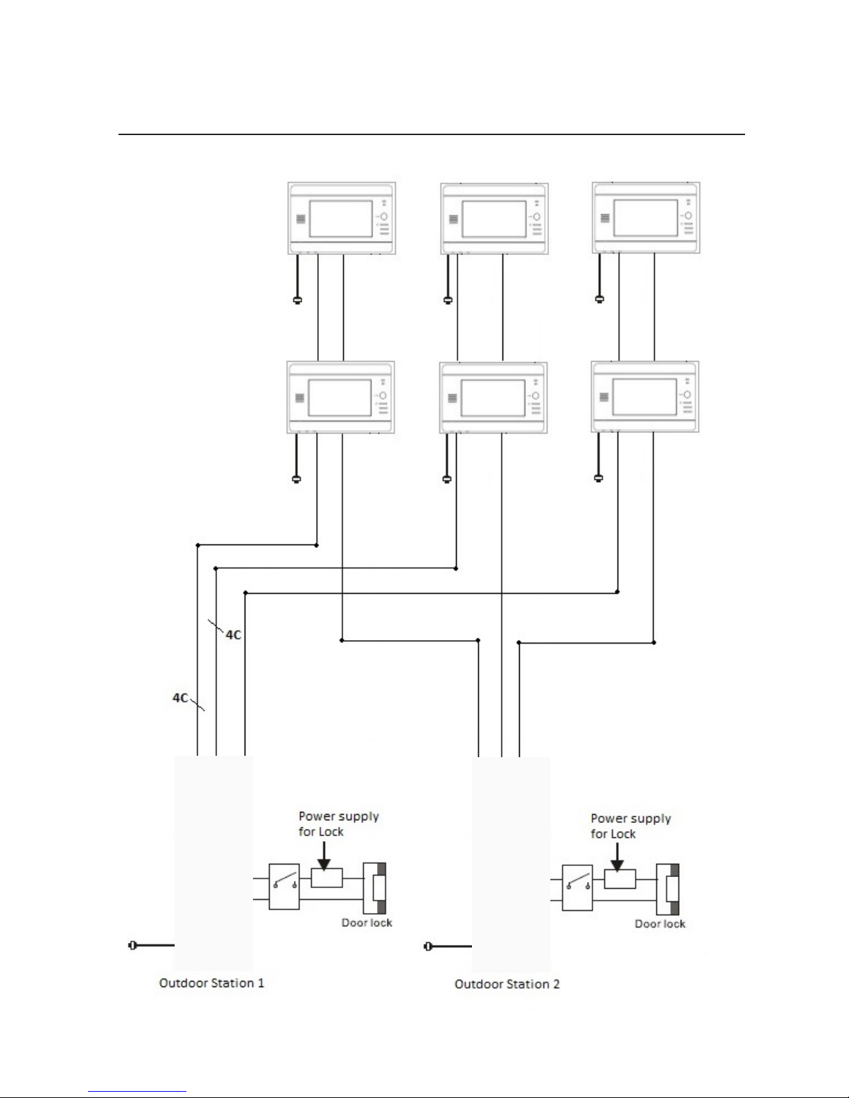
5.2. SVT-MF4 SYSTEM WITH TWO ENTRANCES

-7-
5.3. SVT-4 WIRING CONNECTION
1.
Red 2. Blue 3. Yellow 4. White
4-Vide
o
1-Audio 2-GND 3-V+
5.3.1 Indoor Monitor
1. Red
2. Blue
3. Yellow
4. White
1. Red
2. Blue
3. Yellow
4. White
NOTE: Do not remove any of the jumpers from the back of the indoor
monitors.
By removing a jumper or changing its position, some of the features may
not work properly.
5.3.2 Outdoor Station
Upper module:
CN1: Must remain connected to CN10 port on the lower module.
Lower module:
PWR: Connect a SVT-MF4 PS17 Power supply.
J3: Use this port to connect a door lock. The door lock is limited to 14.5V, 200mA.
Must use an additional power supply for the door lock. Ensure the power supply is
compatible with the door lock specifications. The J3 output is also DRY contact (NO/COM/NC).
CN10: Must remain connected to J1 port on the upper module.
CN22: Reserved port.
JP1: Remove the black jumper if a access control unit is connected to the outdoor station
(SVT-3100 / SVT-4100 / SVT-5100 Access Control System only).
J1: Connect the access control unit (SVT-3100 / SVT-4100 / SVT-5100 Access Control
System only).
CN3: Connect to the indoor monitor (Upper call button)
CN2: Connect to the indoor monitor (Middle call button)
CN1: Connect to the indoor monitor (Lower call button)
CN1: Connect to the first Outdoor Station
CN2: Connect to the second Outdoor Station
Middle module:
PWR: Reserved port.
J4: Use this port to connect an exit button (Use red/black wire with 2 connections).
J1:
Must remain connected to J1 port on lower module.
J3: Reserved port.

-8-

-9-
5.3.3 Electric Door Lock Connection
1. Use the port J3 of the lower module to connect a door lock.
2. The door lock is limited to 14.5V, 120mA.
3. Must use an additional power supply for the door lock. Ensure the power supply is
compatible with the door lock specifications.

6.Cable Requirements
B
A
Cable Usage A B
CAT5 cable (must solder the wires together to ensure a good connection).
Using different cables may affect the maximum distance the system can reach.
230 feet
70 meters
30 feet
10 meters
NOTE:
1. The system expands to a maximum of 2 outdoor stations and 4 indoor monitors.
2. Each indoor monitor requires its own power supply(14.5V, 1.3A)
3. We recommend soldering the wires together to ensure a good connection (Do not use
wire nuts).
-10-
4
.
For long runs typically longer then 90ft, we recommend using coax cable for the video function.

-11
-
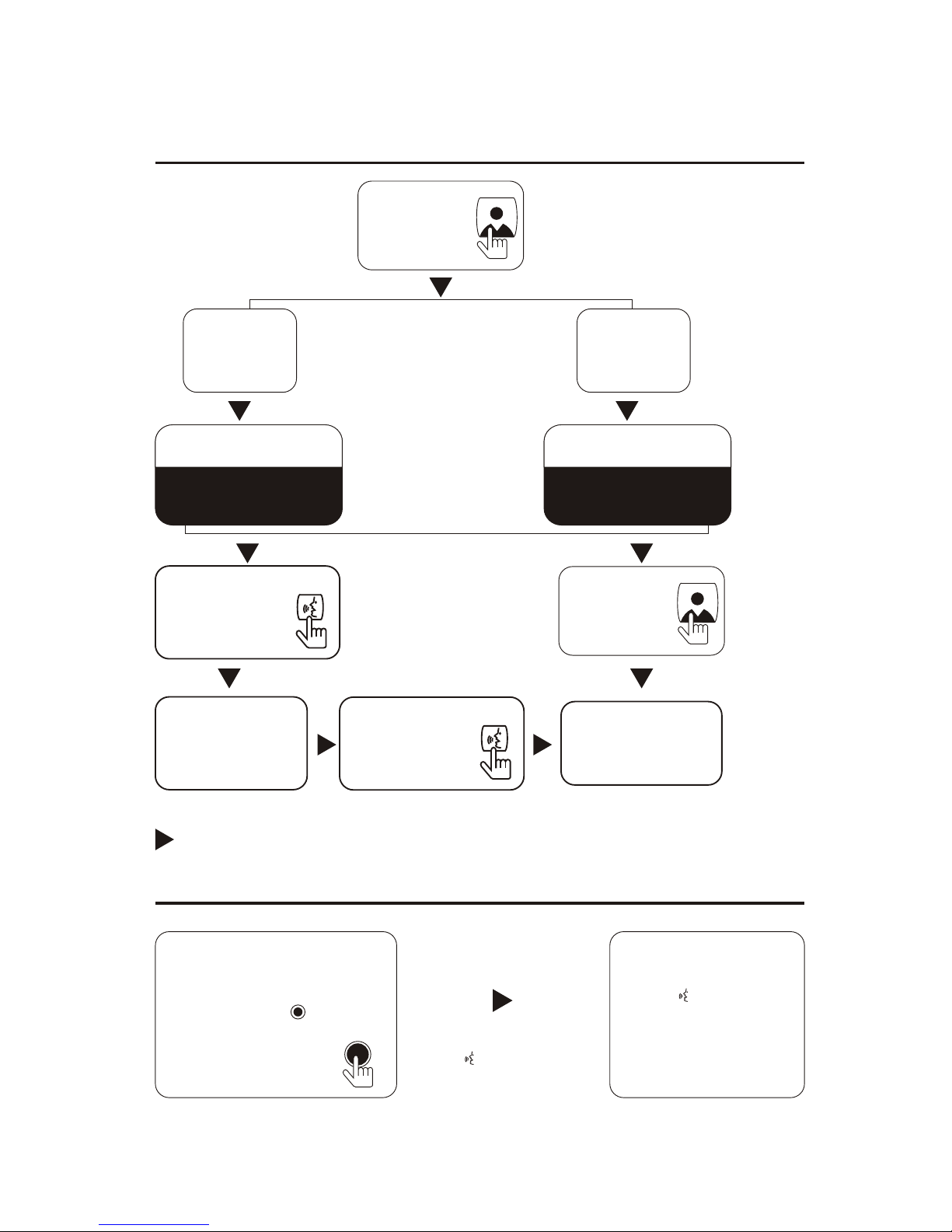
Press the call button at anytime,
the
indoor
monitor
will
show the view
from the front door camera
automatically. Press talking
button to have communication
with the visitor by the front door.
The visitor image shown on
the monitor
7.1 Visitor calls
Check
After pressing the unlocked button,
the indoor monitor still displays
the image from the front door
camera.
End the call
Talk begins
Open the lock
The talk time is
up to 2 minutes
Press the TALK
button
or
hang-up
the
handset
The visitor presses
the call button
on outdoor
station-1
Ring Ring
The visitor presses
the call button
on outdoor
station-2
7.
User instructions
-12-
All indoor monitors
ring
During the conversation
between
the outdoor
station and the indoor
monitor, press button on
the main indoor monitor.
The indoor monitor press
button again
to end the
conversation.
Call transferring from main indoor monitor to extension indoor
monitor
Any indoor
monitor
press button or pick
up the handset to talk
with the outdoor station.
Press twicePress once
The indicator light of
Door 1 is
on.
The indicator light of
Door 2 is
on.
End the monitor
Press the
monitor
button
Monitor outdoor
station 1
Monitor outdoor
station 2
Press the
talk button
Press the
talk button
Monitor the
outdoor station
Press the
monitor
button
7.2 Monitor

-13-
End the call
All indoor monitors
ring
Press the TALKPress the
TALKING button or
hang-upbutton or hangup the handsetthe handset
Talk begins
Any indoor
monitor
presses button or pick up
the handset to talk.
7.3 Intercom
In the standby mode,
press intercom
button in any
indoor monitor
During the talking, any indoor
monitor presses the intercom
button

-14-
8.
How to set up the user codes
SVT-MF4 Outdoor Station G
r
equires the SVT Remote
control for programming.
SVT REMOTE CONTROL works as a remote access
control. It is required to program the SVT-4 Outdoor
Station G settings as registering and deleting
fingerprints, unlocking time and fingerprint security level.
SVT REMOTE CONTROL
Use two AAA alkaline batteries
Sensor working distance: +/- 20cm
Modify administrator code
Enter the setting mode
Input the admin default code twice (1234+1234), the yellow LED will
be on. It is in the setting mode.
The default code is: 1234
In the setting mode:
Press * 3 (Yellow light blinks), and then enter a new administrator
code(XXXX) twice. If Bi- is heard, it means the operation is
successful.
Press # to exit the setting mode.
Notice: In case forget the admin code, power on first, then press #
within 3 seconds. If Bi is heard, it means admin code is
restored as default setting successfully.

-15-
Set the unlocking time
In the setting mode:
Press * 1 (Yellow light blinks), and then enter 2-digit number
from 01 to 99 (Bi- is heard, and yellow light stops blinking). This
2-digit number is the unlocking time. For example, enter 05
means the unlocking time is 5 seconds.
Press # to exit the setting mode.
Add fingerprint
Delete the fingerprint
In the setting mode:
Delete one fingerprint: press 000-899, then press * twice to delete
the fingerprint in 000-899. If light turns green means the deletion
is successful.
Delete all fingerprint: press * 8 (Yellow light blinks), and then enter
8 twice (A continuous Bi - will be heard). The deletion is successful.
Press # to exit the setting mode.
In the setting mode:
Press 000-899 (Yellow light blinks. If red light is on, it indicates the
position is occupied. Press * twice to delete the information in this
position and then add the fingerprint. If green light is on, it indicates
the position is vacant. Fingerprint can be added. ) + put the finger
on the scanner until a Bi sound is heard. Then another Bi and Bi-
will be heard. It indicates the addition is successful. If BiBiBi are
heard, it indicates the addition fails. If BiBiBiBi are heard, it indicates
the fingerprint exists.
Press # to exit the setting mode.
Note: Maximum 900 fingerprints can be registered.
Restore factory default
In the setting mode:
Press * 8 (Yellow light blinks), and then enter 9 twice (A continuous
Bi - will be heard). The factory default is restored.
Press # to exit the setting mode.

Set security level
In the setting mode:
Press * 5 (Yellow light blinks), and then enter security level number
twice(Parameter range is 1, 2, 3, 4, 5. The higher number indicates
the higher accuracy of fingerprint recognition). If Bi- is heard, it
indicates the setting is successful. If Bi Bi Bi are heard, it indicates
the setting fails.
Press # to exit the setting mode.


The design and specifications of this user manual can be changed without any notification to the user.
All copyright and interpretation rights are reserved to SVT Innovations Inc.
 Loading...