

Page 1

SVS MINI 4 LIFT
INSTALLATION MANUAL
SVS, INC. Lifting Your Image
2513 Jenks Avenue Tel: 850-522-4747 Int'l Sales:
Panama City, FL 32405 Fax: 850-522-4739 Tel: 001-303-794-4446
www.svslifts.com
Page 2

SVS MINI 4 LIFT
INSTALLATION INSTRUCTIONS
SECTIONS:
1: Preliminary Installation Checks ----------------------------------------Pg. 4
2: Considerations for placement of the lift ------------------------------Pg. 5
3: Lift's supporting Structure ---------------------------------------------Pg. 5, 6 & 7
4: Lift Installation ----------------------------------------------------------Pg. 8
5: Ceiling Closure Installation ---------------------------------------------Pg. 8
6: Electrical Wiring and Lift Control ------------------------------------ Pg. 9 & 10
7: Mounting the Projector ------------------------------------------------Pg 11
8: Cable Management -----------------------------------------------------Pg 11
9: Setting the Show Position ----------------------------------------------Pg 12
10: Maintenance and Adjustment
SVS Mini 4 Lift Warranty ------------------------------------------------Pg. 13
s ------------------------------------- Pg 12
Page 3
SVS MINI 4 LIFT
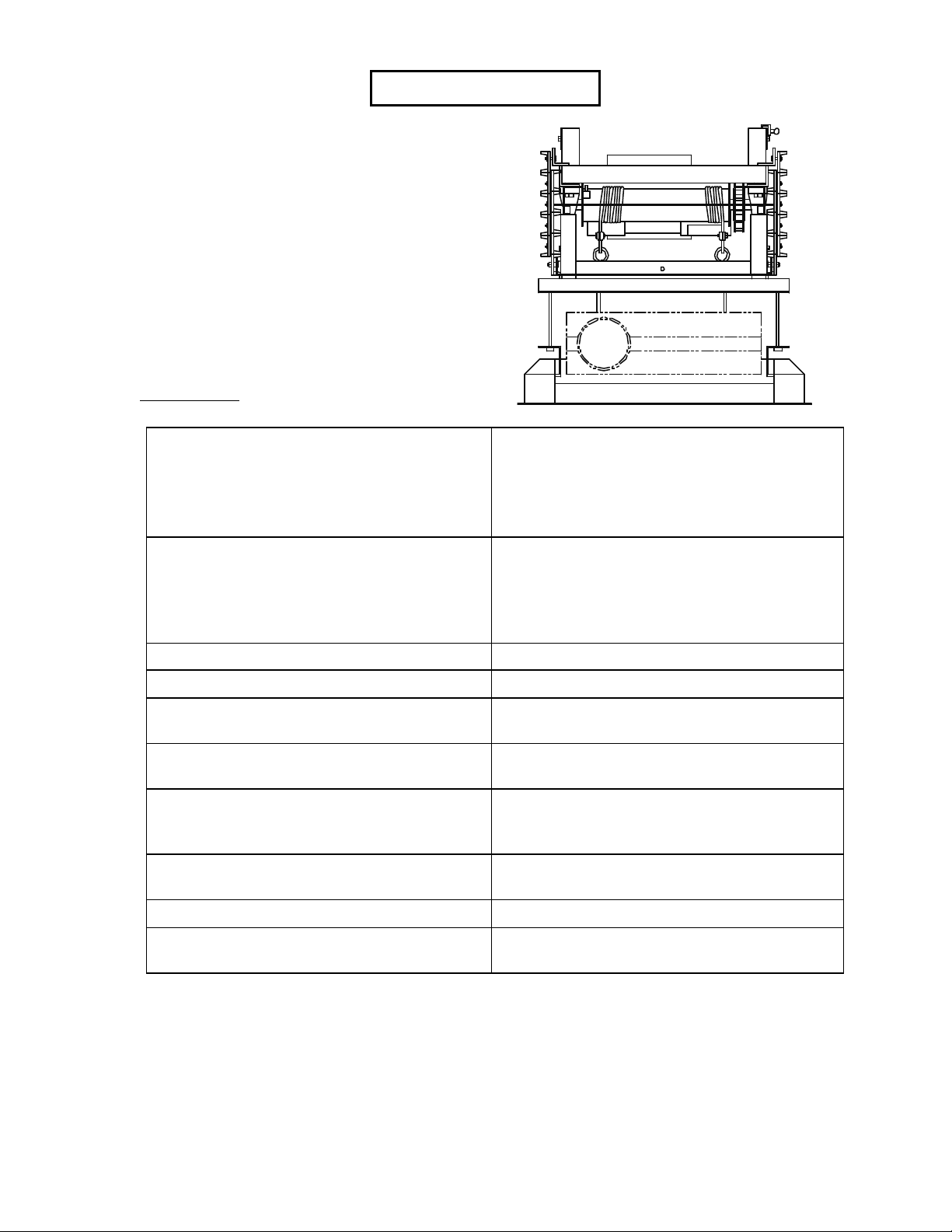
GENERAL DESCRIPTION:
The SVS Mini 4 Lift is one of SVS, Inc.'s smallest
footprint. It is designed to support small
LCD/DLP projectors. This model has been
designed with the safety issue in mind: it features
redundant limit switches in up and down
positions, a grooved cable drum for leveled and
accurate image tracking and a patented drum lock
system. The SVS Mini 4 Series lift can be used in
commercial and residential applications.
FEATURES:
MAXIMUM LOWERING DISTANCES:
SVS MINI 4-3: 3'6" (1.07 m)
SVS MINI 4-5: 4'9" (1.45 m)
SVS MINI 4-6: 6' (1.83 m)
STORAGE, SHOW, SERVICE POSITIONS
LIFTING CAPACITY
LIFT'S WEIGHT
LOW VOLTAGE CONTROLLER
PRECISION GROOVED DRUM
PATENTED FAIL SAFE DRUM LOCK SYSTEM
QUIET AND STRONG MOTORS
REDUNDANT LIMIT SWITCHES (UP AND DOWN)
LIFT'S HEIGHT IN CLOSED POSITION:
12" (30.5 cm)
15" (38.1 cm)
18" (45.7 cm)
(Note: Height of the lift only. Projector's height is additional)
Projector can easily be:
- Aesthetically stored above the ceiling when not
in use
- Automatically positioned for show/operation
- Easily lowered to floor level for service
400 Lbs (181.44 Kg.)
From 100 Lbs (45.5 Kg.)
Supplied with 75' (22.86 m) of cable (22
gauge/9conductor).
Accurate, level tracking for consistent screen
image
Insures safety in the event of mechanical
failure. 100% safety record after 14+ years of
manufacturing
Extra quiet for meetings and presentations or
simply for home use.
For secure and safe motor shutdown.
CABLE MANAGEMENT SYSTEM
SVS MINI 4 LIFT INSTALLATION Page 3 of 13
Keep cables and cords out of the way during
operation.
Page 4

PLEASE READ THROUGH ALL INSTRUCTIONS (INCLUDING ACCESSORY
INSTRUCTIONS) BEFORE PROCEEDING.
This lift is designed to be used with a remote control unit, either automatically or manually
controlled and will function without any special training in the "show position". The lift is
supplied with a key switch and can be left in the "show", "auto" or "off" position for normal
operation. The "service" position must be used only by trained technical personnel when the
lift is lowered to floor level for service/access. Normal safety requirements of handling heavy
equipment must be followed.
1. PRELIMINARY INSTALLATION CHECKS:
• The support structure should hold at least four (4) times the weight of the lift and projector combined.
Always follow the building codes.
• Required space, lift support, and necessary cabling (i.e. low voltage control lines, audio/video control
and power supplies) should be considered or installed prior to the lift installation.
• Do not install the projector on the lift until the lift, hardware and any other accessories have been
properly installed and operational.
• This lift has been adjusted at factory with cables tightly packed on the drum and leveled for precise
tracking, prior to being shipped from SVS Factory. Do not remove the lift's shipping blocks until
instructed to do so (see Section 4-6). SVS scissor lifts are shipped in a slightly open position to
eliminate stress on the limit switches and to maintain a tight cable pack on the drum. If physical height
measurements are taken before the blocks are removed from the lift, they may not accurately reflect
the actual measurement of the lift in a closed position.
• All weight attached to the lift must be centered between the lift's cables. The balance point of the
projector (also called center of gravity or lens face to base box center) should be placed in line with the
cables (+ /- 1").
• For ease of installation, lift can be hoisted into ceiling location with blocks and tackle or by using a
ratchet puller.
• As a reminder, clear all persons and obstructions from the lift's path during its operation. Keep fingers
and other objects away from the scissors and other moving parts. Technical Personnel should always
be present whenever the lift is in a service mode.
SVS MINI 4 LIFT INSTALLATION Page 4 of 13
Page 5
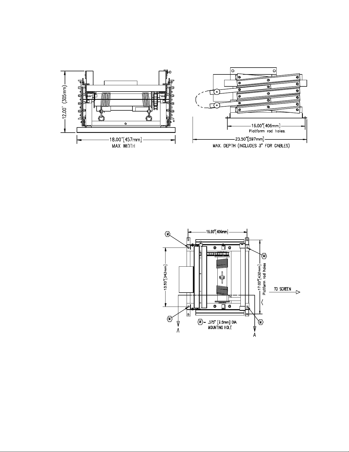
2. CONSIDERATIONS FOR THE PLACEMENT OF THE LIFT:
• Before beginning the installation, check the dimensions of the projector to be mounted against the
available space within the lift. Be sure to include the lens or any accessories which may add to the
overall dimensions of the projector- see figure 1 & 2.
Figure 1 (Mini 4-3 shown) Figure 2.
• Preliminary measurements should also be made to layout the orientation of the projector to the screen
and projector to lift. If the projector lens if offset, the lift position must be offset accordingly to align
the lift and the projector with the center of the screen.
3. LIFT SUPPORTING STRUCTURE:
The Mini 4 Lift can be mounted
from four .375" threaded rods
spaced at 13.5" Wide (34.3 cm) x
16" Deep (40.6 cm) -as shown in
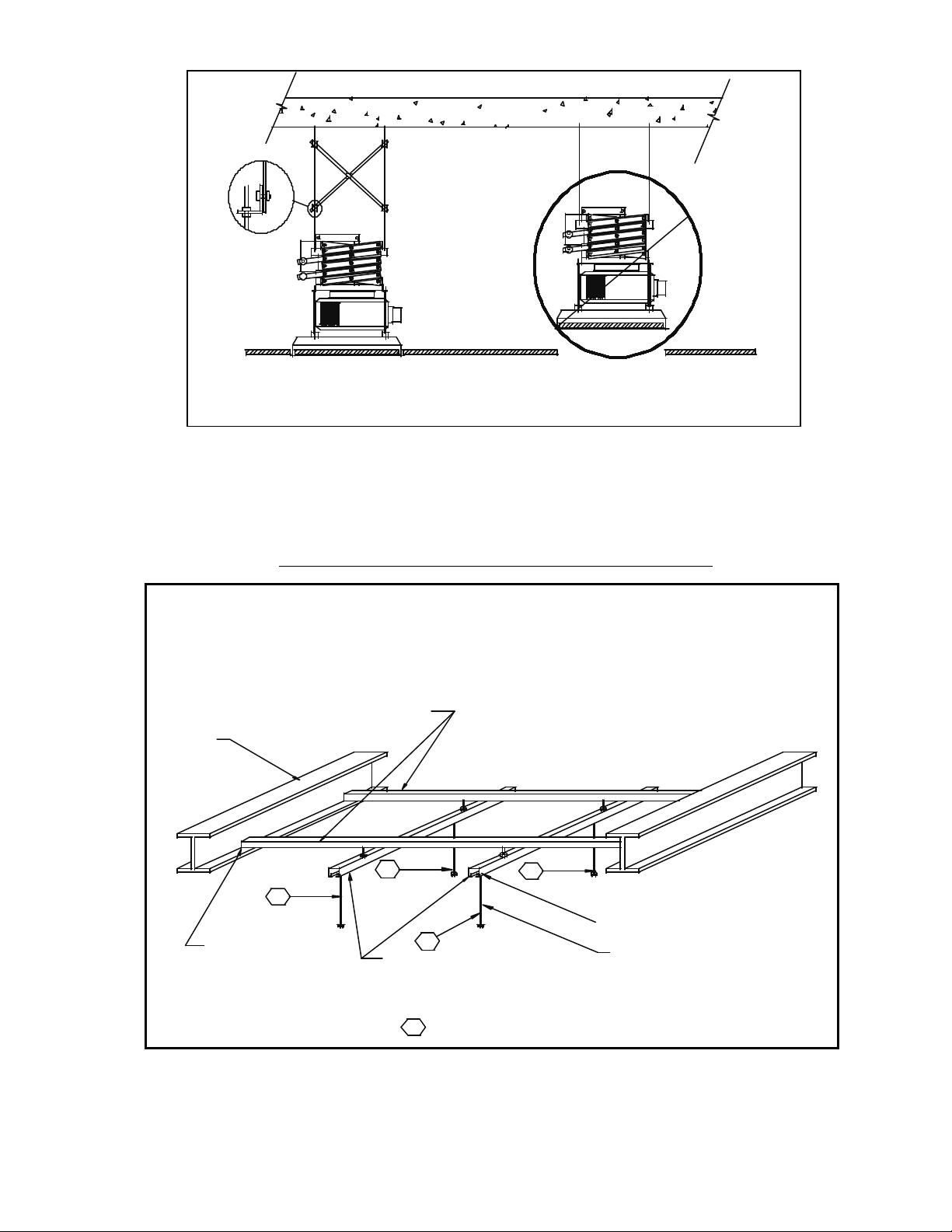
figure 3. The threaded rods must
be supported by a rigid structure
and should not extend more than
2' (0.6m). If the length of the rods
exceed 2' (from the support
structure to the lift's top mounting
holes), cross bracing should be
installed between the rods to
increase the stability of the
installation -see figure 4.
Figure 3.
SVS MINI 4 LIFT INSTALLATION Page 5 of 13
Page 6
MAIN CEILING
TO ACHIEVE PROPER HEIGHT.
CROSS BRACING
FALSE CEILING
CORRECT HEIGHT FOR FALSE CEILING
ADJUST THREADED ROD LENGTH
INCORRECT HEIGHT
Figure 4.
If ceiling clearance allows, an "X-Y" or a cross-supporting structure is strongly suggested (as shownin two
following suggested supporting structures). This will allow front-to-back or side-to-side adjustments if the
lift is found to still be slightly offset with the screen once it has been installed.
SVS MINI 4 LIFT MOUNTING ON EXISTING BEAMS
ALWAYS FOLLOW THE LOCAL BUILDING
CODES. SVS RECOMMENDS THAT ALL MOUNTING
HARDWARE IS RATED TO HANDLE 4 TIMES
THE WEIGHT OF THE PROJECTOR
AND LIFT OR WHICH EVER NUMBER
IS HIGHER.
DO NOT EXCEED RATING OF
UNISTRUT BY SPANNING TOO GREAT
OF A DISTANCE.
1/2" THREADED
RODS 4 PLCS.
EXISTING
BEAMS
2 PLCS.
X - UNISTRUT P1000 T
2 PLCS.
SVS MINI 4 LIFT INSTALLATION Page 6 of 13
M
M
BEAM CLAMP
UNISTRUT P2824
4 PLCS.
* MOUNTING MATERIALS NOT SUPPLIED BY SVS, INC.
M
Y - UNISTRUT P1000 T
2 PLCS.
M
M
= MOUNTING HOLES
Figure 5a.
UNSTRUT CHANNEL NUT
P3010 WITH WASHER
AND RETAINING NUT.
8 PLCS.
THREADED ROD, 4 PLCS.
.375" FOR MINI 4 AND
LCD LIFTS
.5" FOR ALL OTHER
LIFTS
Page 7
SVS MINI 4 LIFT MOUNTING ON A FLAT CEILING
= MOUNTING HOLES
ALWAYS FOLLOW THE LOCAL BUILDING
CODES. SVS RECOMMENDS ALL MOUNTING
HARDWARE BE RATED TO HANDLE 4 TIMES
USE NO LESS THAN EIGHT 1/2"
MACHINE THREAD SHIELDS AND
BOLTS TO SECURE TO CEILING.
M
M
USE 10'LENGTH WHEN
POSSIBLE ON EACH X AXIS
MOUNTING MATERIALS NOT SUPPLIED BY SVS, INC.
Y - UNISTRUT P1000 T
2 PLCS.
X - UNISTRUT
P1000T 2 PLCS.
M
THE WEIGHT OF THE PROJECTOR
AND LIFT OR WHICH EVER NUMBER
IS HIGHER.
M
UNSTRUT CHANNEL NUT
P3010 WITH WASHER
AND RETAINING NUT.
8 PLCS.
THREADED ROD, 4 PLCS
.375" FOR MINI 4
AND LCD LIFTS
M
.50" ALL OTHER LIFTS
1/2" THREADED
RODS 4 PLCS.
Figure 5b.
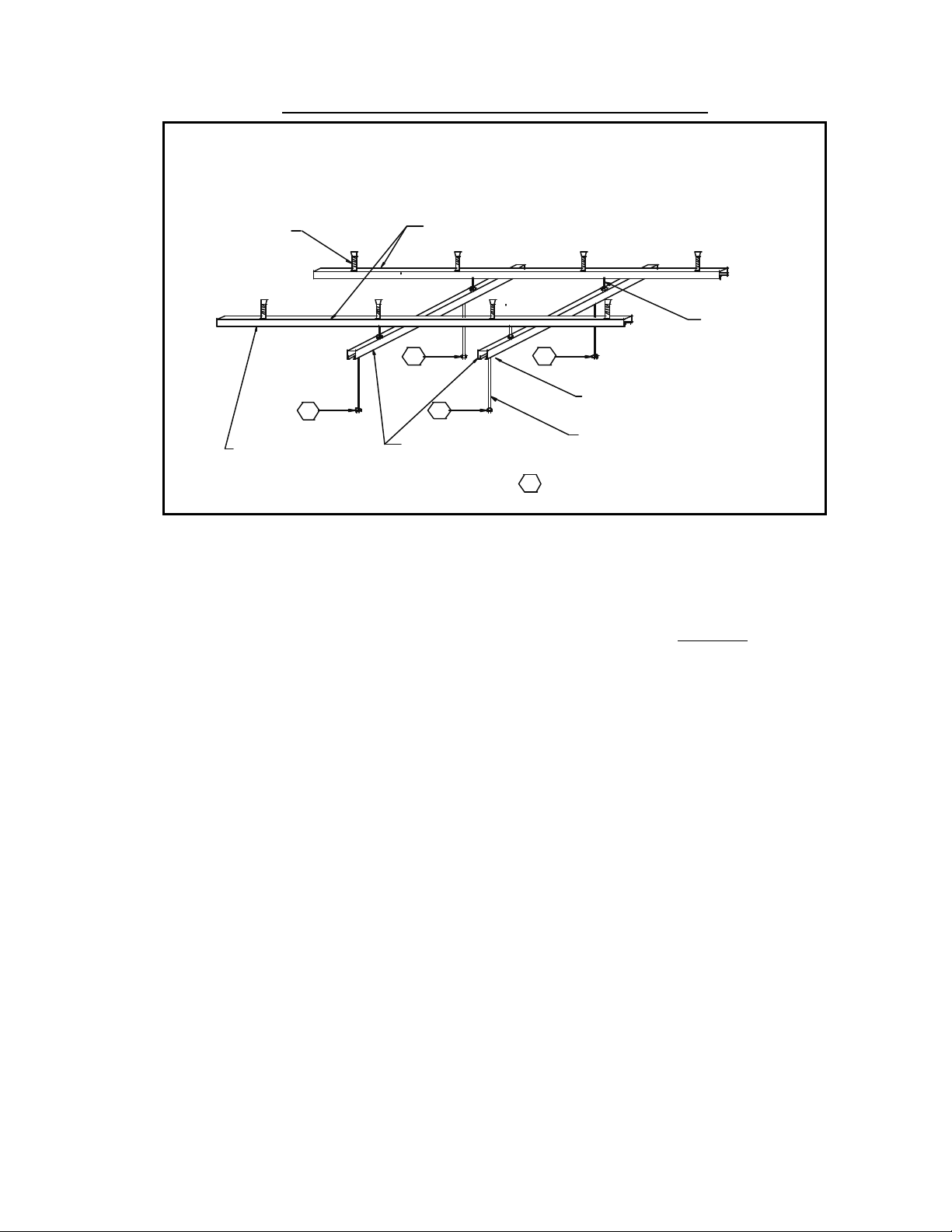
Important note for concrete ceiling installations: when attaching the lift to a flat ceiling, SVS suggests
two (2) pieces of #P1000T Unistrut (approx. 10' long -3.04 m), to be installed on the ceiling first. Proper
spacing between the 2 pieces will be based on the distance between the top four (4) mounting holes of the
lift (as shown in Figure 1) .
You should use at least four (4) ½" bolts and anchors evenly spaced our on each piece of Unistrut to
distribute the weight of the supporting structure. Attach ½" threaded rods to the Unistrut, using Unistrut
#P3010- ½" channel nuts in the channel, along with a locking washer and nut below channel to lock into
place.
SVS MINI 4 LIFT INSTALLATION Page 7 of 13
Page 8
IMPORTANT: IF A #2 PLENUM SHROUD OR A #12 DECORATIVE COVER ARE TO BE INSTALLED
WITH THE MINI 4 LIFT. PLEASE READ THEIR INSTALLATION INSTRUCTION BEFORE
PROCEEDING. THE SUPPORTING STRUCTURE SHOULD ALSO ALLOW ENOUGH SPACE TO
INSTALL THE MOUNTING HARDWARE OF THE DECORATIVE COVER AND THE PLENUM
SHROUD.
4. LIFT INSTALLATION:
a. Preparation:
1. The lift is shipped in a wood crate. Remove the Philips screws from the top lid.
2. Unbolt the lift from the bottom panel of the crate to remove the lift out of the crate.
3. The warranty information and the low voltage controller are located in the white box.
b. Installing the lift in the ceiling:
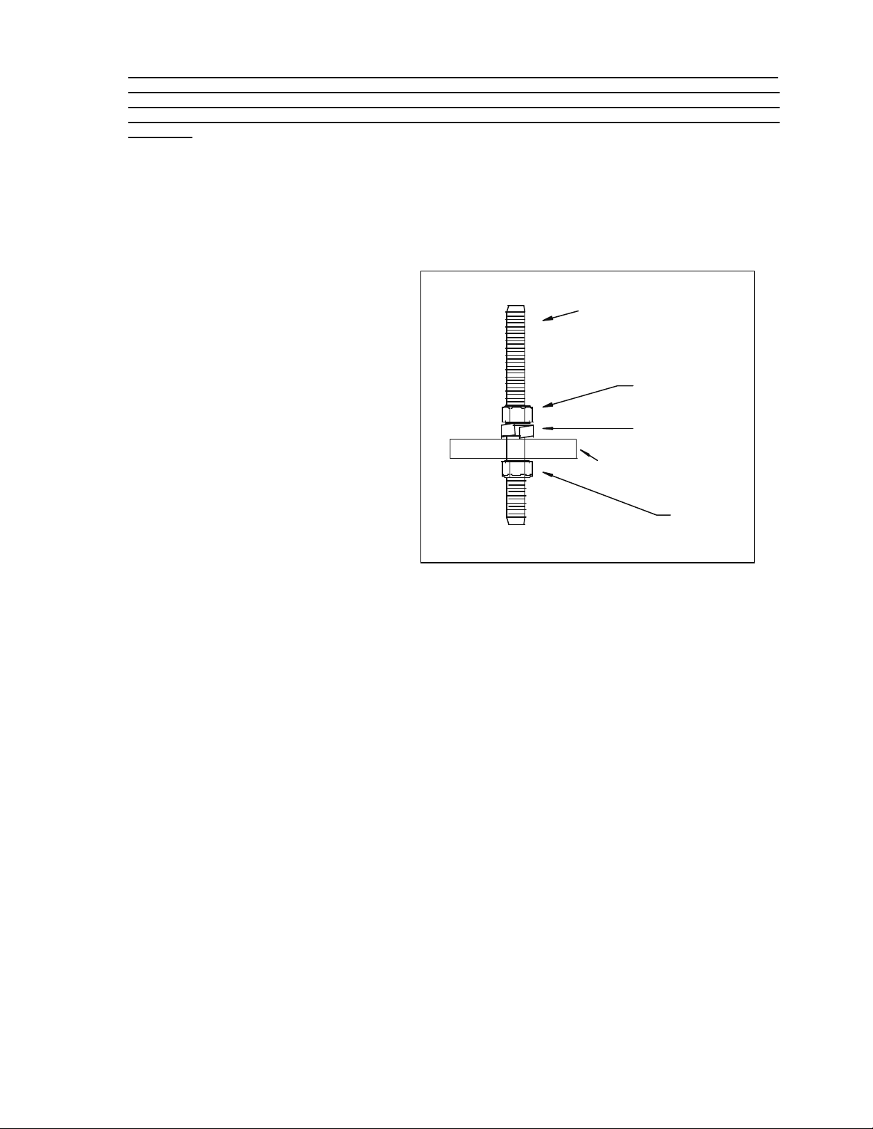
1. Raise the lift, insert it into the ceiling
.375" THREADED ROD
and line up the four (4) mounting holes
of the top frame to the .375" threaded
rods of the supporting structure. Make
sure that there is a top nut and a flat
washer before the lift is mounted -see
HEXNUT
figure 6. Once the lift's top frame has
been inserted, add an hexnut to each
LOCK WASHER
threaded rod. Always leave top nut loose
to allow adjustments until the lift is
TOP FRAME OF LIFT
leveled.
2. Secure the lift to the threaded rods.
HEXNUT
3. Check that the top frame of the lift is
leveled from front-to-back
and side-to-side.
Figure 6.
4. Secure the top nuts. Do not over tighten the fasteners before the lift is leveled as it could distort the top
frame.
5. If Power Sensor is used, please refer to the power sensor instructions, otherwise, plug in the 12 pin
connector of the low voltage controller (the Key Switch Control Box) into the 12 pin receptor of the grey
electrical box, which is supplied with the lift and shipped in the white box located underneath the lid of the
shipping crate.
6. Remove the four (4) shipping Blocks from the lift. Never remove the blocks until the lift is properly
installed in the ceiling.
7. Make sure that cables are out of the way of operation.
8. Before lowering the lift, you should have some weight attached to the bottom of the lift in order to
keep the cables tight until the projector is mounted. Both cables are placed on the drum so that they start
unwinding from the inside to the outside of the drum. They are vertical to the eye bolts in the closed
position and slightly angled toward the outside of the drum to avoid friction/rubbing with the previous
cable loop.
To avoid cable spill:
- Do not push the bottom frame upward once the lift has been installed.
- Make sure that there is no obstructions in the lift's path. If the bottom frame lowers onto a chair,
table or any other object, this will cause the cables to slack and spill over the drum.
5. CEILING CLOSURE INSTALLATION – Please refer to installation instructions included with
the #1 Ceiling Closure. It is the self-aligning closure system installed underneath the projector and used to
conceal the ceiling hole when the lift and projector are raised in the ceiling. It is attached to the four (4)
mounting holes of the lift's bottom frame with threaded rods.
SVS MINI 4 LIFT INSTALLATION Page 8 of 13
Page 9
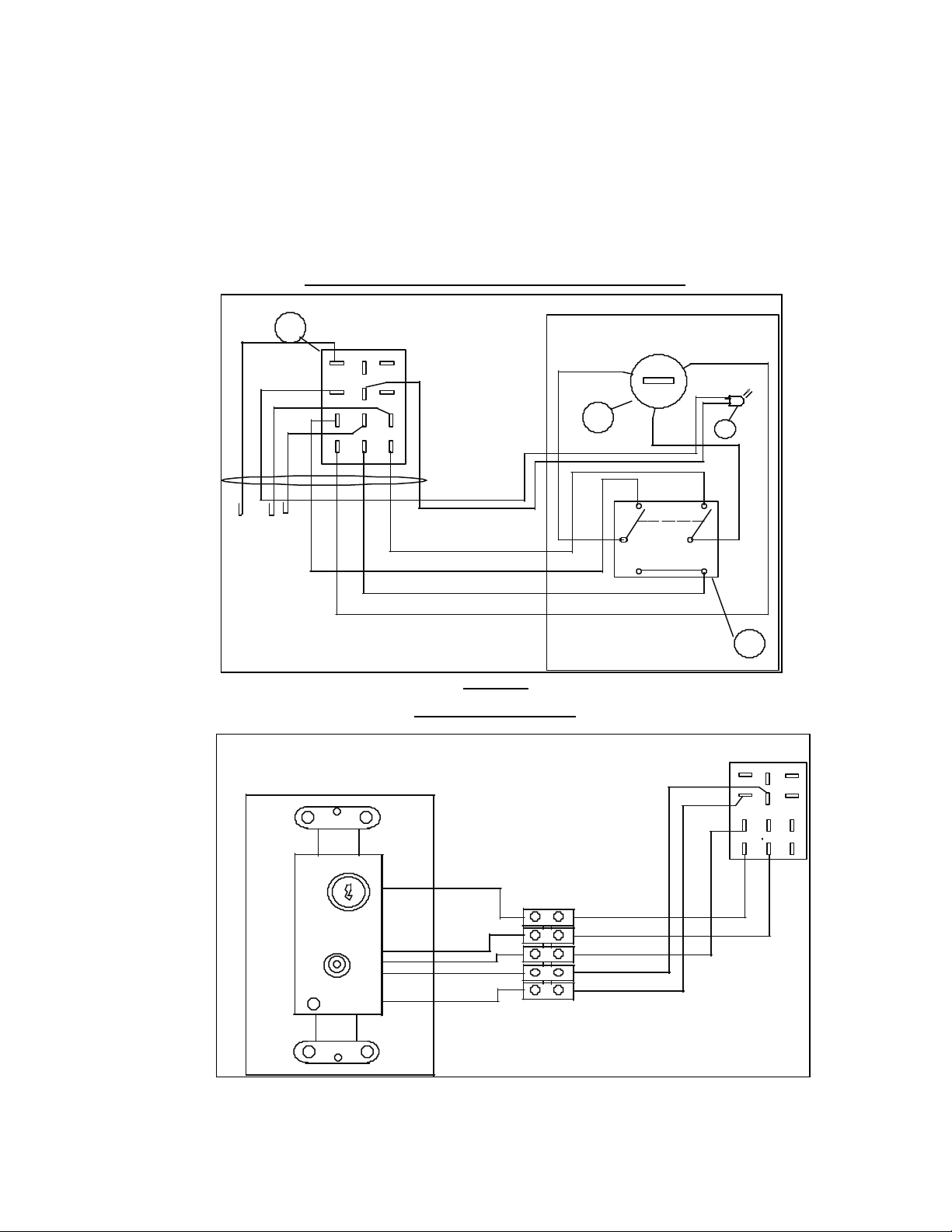
6. ELECTRICAL WIRING AND LIFT CONTROL:
Electrical Connections should be made at this time. The Mini 4 lift is controlled with a low voltage
24v/AC controller called the Key Switch Control Box. This controller can be easily connected to
external controllers like Crestron, AMX etc. Depending on the application, the controller exists in two
versions:
• The SVS Standard Key Switch Control box supplied with 75' of cable -as shown figure 7a.
• The SVS Wall Plate -which is practically the same as the key box but designed to fit in a single gauge
wall plate. It also features a terminal strip for easier wiring connections -see figure 7b.
STANDARD KEY SWITCH CONTROL BOX
RP2
77
YEL
BLK
PUR
BLU
10
7
12
11
8
9
4 5 6
321
ORN
BRN
GRN
RED
WHT
SVS WALL PLATE
SVS Wall Plate
SHOW
OFF
SERVICE
UP
DOWN
PWR
BLK
Figure 7a.
Wht
Red
Grn
Orn
Blk
(SERVICE)
WHT
Terminal Strip
SHOW-OFF-SERVICE
(24vac)
C
1
80
GRN
Wht
Red
2
(SHOW)
DOWN
UP
Grn
Orn
Blk
MOTOR
POWER ON
+
93
BRN
WHT
51
RP2
10
7
4 5
1
11
8
2 3
12
9
6
Figure 7b.
SVS MINI 4 LIFT INSTALLATION Page 9 of 13
Page 10
How to use the low voltage controller:
a. To lower the lift to the show position, turn the keyswitch to the "show" position and press the toggle
down. The lift will stop once the roller compresses the show microswitch. The service mode is used to
bypass the adjusted show position and to set the lift in a service mode, turn the keyswitch to the "service"
position and press the toggle switch down. When the lift reaches its down limits, the lift will stop.
b. To raise the lift back to a storage position, turn the keyswitch to "service" and press the toggle switch
up. The lift will stop once its top frame compresses the up limit switches.
Note: The "up" switch works in both "service" and "show" position on the key switch.
Important:
when the lift is set in a service mode, the lift will lower until it has reached its down limit
switches. The toggle switch on the control plate needs to be pressed at all times to activate the lift. It is
designed as a safety feature (the lift can be stopped at any time). The key is an extra precaution as well:
when removed, the lift is secured. If an external controller is use, please make sure that no object is
standing in the lift path as it lowers to a service position.
LIFT SPECIFICATIONS
USA INTERNATIONAL
VOLTAGE
LOW VOLTAGE CONTROLLER 24v/ac 24v/ac.
CURRENT DRAW 2.3 amps 2.3 amps/1.2 amps
MATERIAL Steel/Aluminum Steel/Aluminum
110V/60HZ 220V/50HZ
Power Requirements: 110v/50-60hz -220v/50-60hz
Low Voltage Controller: Supplied with the lift. 12 pin connector plug. 75' of
Cable (22 gauge/9 conductor).
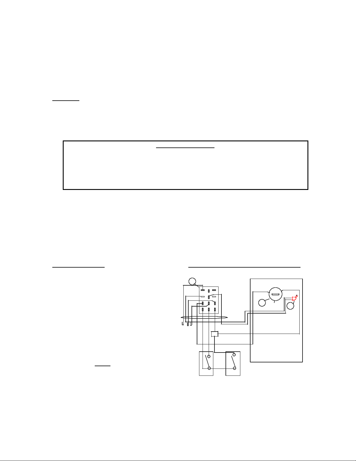
WHEN USING A TOUCH SCREEN CONTROLLER:
If an external controller is to be used (AMX, Crestron), please refer to the following wiring instructions
-see figure 8.
INSTRUCTIONS:
Program a release of relays to stop on up and
down positions.
Program a time out after the normal run
time, 1 or 2 seconds max.
Wiring using Touch Screen Controller
77
BLK
PUR
BLU
10
7
4 5 6
RP2
11
8
12
9
321
SHOW-OFF-SERVICE
(SERVICE)
GRN
80
C
1
POWER ON
2
(SHOW)
MOTOR
+
93
1. Program an exclusive lockout on up and
BRN
GRN
ORN
BLK
BRN
down so both positions cannot be activated
at the same time.
2. Hold relays on to move the lift and
release relays to stop the lift -always time out
RED
3
WHT
or release relay after normal use.
IMPORTANT: Never
up and down. Always release voltage
immediately after the travel time has been
achieved.
IF USING ANY OTHER SYSTEMS, PLEASE CONTACT SVS FOR PROPER WIRING TO AVOID
UNSAFE OPERATIONS.
leave voltage on the
UP DOWN
24VAC
TOUCH SCREEN
RELAY ONE
TOUCH SCREEN
RELAY TWO
Figure 8
VIEW FROM BACK
SVS MINI 4 LIFT INSTALLATION Page 10 of 13
Page 11
7. MOUNTING THE PROJECTOR:
WIRE TIE AROUND POWER CORD, AND VIDEO LINE
After checking the lift operation and all clearances, the projector can be installed. The projector can be
mounted in two ways: inverted or platform mounted.
– The projector can be attached to the lift
by using a #9 Mounting Bracket, which is
the actual connecting hardware between
the projector and the lift. The base box
of the #9 mounting bracket will need to
be bolted to the lift. The mount base
should be centered side to side with the
MOUNT
lift frame.
PROJECTOR
Figure 9.
– If the projector is non-invertible, it can be placed on a SVS #13 platform (metal shelf used to support
projector).
Note: All weight attached to the lift must be centered between the cables. Balance point of the projector
should be placed in line with cables with +/- 1" of difference.
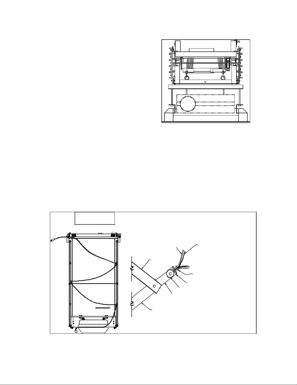
8. CABLE MANAGEMENT:
The SVS Mini 4 Series lifts all feature cable retainers installed on the scissor extensions in the rear of the lift.
These retainers are used to keep cables and other cords securely out of the way during operation. It is not
suggested to attach the cables to the scissors of the lift as they could get repeatedly pinched when the lift
raises and lowers. To keep projector cords away from scissors, please attach cords as demonstrated in
figure 10.
VIEW FROM BACK
OF PROJECTOR LIFT
VIDEO CABLE
WIRE TIE AROUND EXTENSION, POWER CORD,
AND VIDEO LINE
VIEW - A
(ENLARGED TO SHOW DETAIL)
VIEW - A
BACK OF
VIDEO PROJECTOR
POWER CORD
SCISSOR
WASHER
EXTENSION
SCISSOR
SVS MINI 4 LIFT INSTALLATION Page 11 of 13
Figure 10.
Page 12
9. SETTING THE SHOW POSITION:
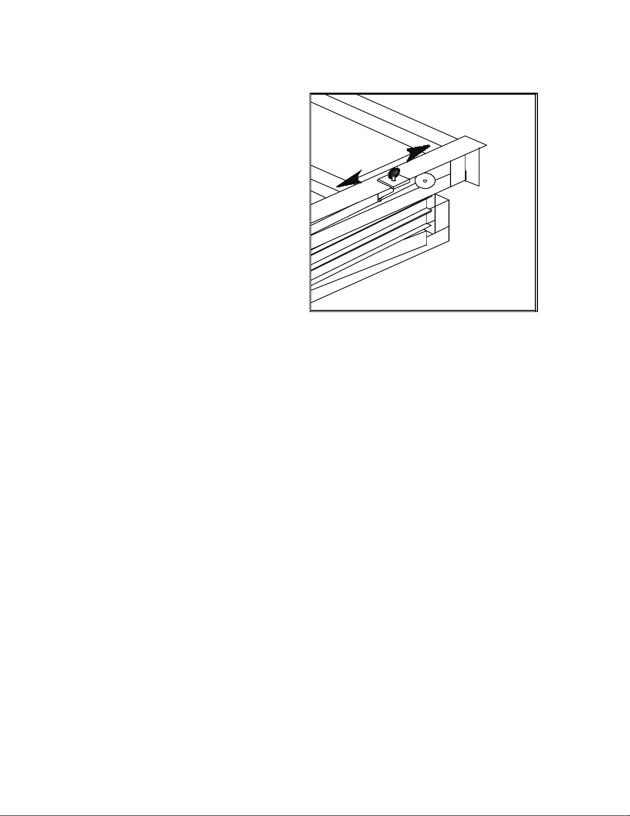
The show position is adjusted by loosening the thumb screw on the show microswitch bracket, located on
the upper motor frame -as seen in figure 11:
a. Operate the lift in a service mode and
lower the lift to the desired show
REAR OF LIFT
position.
b. Loosen the thumb screw and slide the
show microswitch along the roller guide
ADJUSTABLE SWITCH
until it touches the larger retainer washer
(as you position the switch over the roller,
you should hear a slight click when the
microswitch is compressed). Make sure
that the microswitch is not positioned too
close to the washer because it must pass
over it when the lift lowers to a service
position.
c. The show position is now set. Raise the
lift back to a closed position, turn the key
switch to the "show" position and press
the toggle down. The show
position is adjustable with an accuracy of
+/-1/8" (0.32 cm). Figure 11.
10. MAINTENANCE AND ADJUSTEMENTS
• Inspect the lift occasionally for any looseness of bolts, check cables and clamps. Pillow block bearings
are pre-lubricated and motor does not need attention. If magnetic brake does not hold properly, it
must be replaced immediately.
• Level corrections are to be made (with projector mounted) after confirming that the cable is packed
tightly and is straight on the drum.
• Position a level across the front of the projector. Fine alignment is done by adjusting nuts on the
bottom of the eye bolts. Track up and down until satisfactory alignment is achieved.
• For projectors mounted within the ceiling and lowered to a viewing position, level adjustments must
be made at the viewing level.
• After adjustments are completed, check all bolts and clamps for tightness.
• Check drum lock solenoid occasionally – see if arm raises during downtravel – all other times it stays
in a locked position. If the solenoid does not pull up, the microswitch will not start motor in the
down position. Check the centrifugal cam located on the drum stop block. It should be able to
move freely and will drop when it reaches the top of the drum, this avoiding contacting the arm of
the drum lock. If drum rotates fast, the cam will lock the arm after the first rotation.
• All scissor bolts are adjusted for no slack, but must not be too tight. To adjust, tighten to
approximately 151 Lbs Torque, then back of 1/8". These bolts have nylon locking nuts and should
stay at this position.
SVS MINI 4 LIFT INSTALLATION Page 12 of 13
Page 13

SVS MINI 4 LIFT Warranty
SVS provides a limited warranty on all products to cover failures due to defects in materials or
workmanship which occur during normal use. This limited warranty does not cover failures
which result from accident, misuse, abuse, neglect, mishandling, misapplication, alteration,
faulty installation, modification or service by anyone other than a factory authorized person or
company. Specific product warranties are as follows:
A 5 year parts and 90 day factory labor warranty applies to the following SVS products:
• All scissor style lift models (does not include LCD-1 and Plasma One Lifts)
• Acc. #4 Power Sensor
• Acc. #5 Power Sensor with Screen Control
• Acc. #7 Cable Retractor
• Acc. #11 Extra Show Position
• Acc. #14 Floor Access Motor Control
• Acc. #15 12 Volt trigger
A 1 year parts and 90 day factory warranty applies to the following SVS products:
• SVS LCD-1 Lifts (S and L models) and Plasma One (4 & 7 models)
• All motors
• Acc. #1 Ceiling Closure
• Acc. #2 Plenum Shroud
• Acc. #9 Mount
• Acc. #10 Dual Stack Mount
• Acc. #13 and 13R platforms
A 60 day factory labor warranty applies to:
• Acc. #12 Decorative Cover
A Return Material Authorization (RMA) number must be received from SVS prior to the return
of any product. Products returned from SVS must be shipped adequately insured with freight
prepaid and the RMA number clearly noted on the shipping label. Items received freight collect
or without RMA numbers clearly noted will be refused. Lift model, serial number and proof of
original purchase date may be required before warrant performance is rendered.
_____________________ ______Cut-Here __________________________
WARRANTY CARD
CUSTOMER NAME ___________________ SERIAL #___________________
ADDRESS ___________________________ MODEL # SVS MINI 4-
CITY____________ ST______ ZIP _______ DATE PURCHASED __________
PHONE _____________________________ DATE INSTALLED ___________
PURCHASED FROM __________________ SEND TO: SVS, INC
DEALER NAME ______________________ 2513 Jenks Avenue
ADDRESS ___________________________ Panama City, FL 32405
CITY ___________ ST ______ ZIP _______ PHONE: 850-522-4747
PHONE _____________________________ FAX: 850-522-4739
CARD MUST BE SENT IN WITHIN 10 DAYS FROM DATE OF INVOICE
SVS MINI 4 LIFT INSTALLATION Page 13 of 13
 Loading...