

Page 1
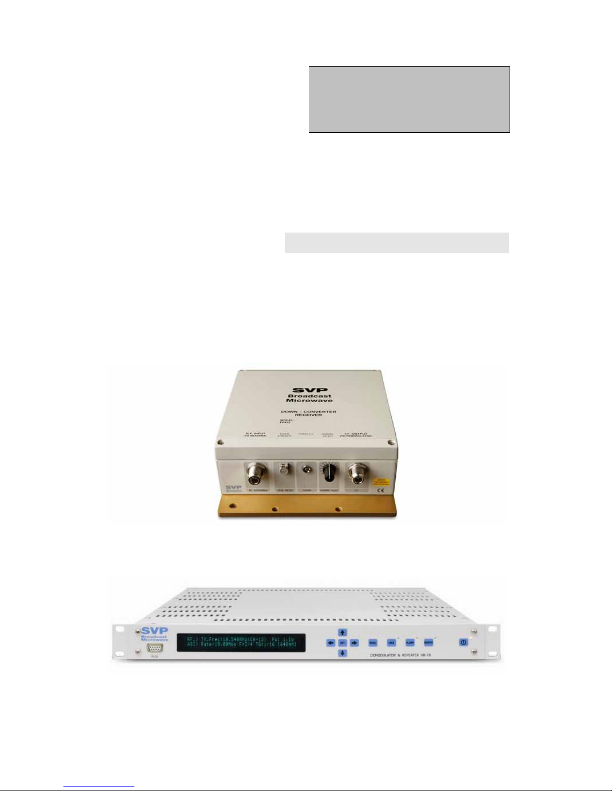
SVP
Broadcast
Microwave
VR-70 & DCM-1070
User’s Manual
V 1.1
10GHz Receiver
Page 2

Preliminary pages
VR-70 and DCM User’s Manual Page 2
Contents
Chapter 1: VR-70 Demodulator and Repeater
The objective of this first part is to provide a detailed description of the DR100 series receivers. First of all, there is a theoretical explanation of how
the equipment works. Secondly, a description of its main characteristics
and options is given. Finally, information of how to operate the equipment
is provided.
Chapter 2: DCM-1070 Multi-frequency Down-Converter
This second chapter describes the operation mode, options and main
characteristics of the DCM-1070 multi-frequency down-converter.
Chapter 3: Parabolic antenna Installation
The target of this third section is to describe how to do the installation of
the parabolic antenna for a point to point link.
Firstly, a general description of the assembly is given. Next, there is a more
extensive description offered by the manufacturer himself.
Chapter 4: MD-70 Signal External Meter
This last part, aims to give a general explanation of the options and
characteristics of the signal external meter.
Page 3
Preliminary pages
VR-70 and DCM User’s Manual Page 3
Page 4
Preliminary pages
VR-70 and DCM User’s Manual Page 4
Page 5

Preliminary pages
VR-70 and DCM User’s Manual Page 5
DEAR CUSTOMER
We would like to thank you for selecting this equipment, and welcome you
to the SVP’s growing family products.
We are sure that the addition of this equipment to your existing installation
will cause you nothing but satisfaction.
Please read these instructions carefully, and keep them in hand in case you
have to refer to them.
Page 6

Preliminary pages
VR-70 and DCM User’s Manual Page 6
IMPORTANT NOTES
1. While installing the VR-70 Demodulator, the DCM Down-converters
and/or the UCM Up-converters, the power supply of the down-converters
and the up-converter should be disabled in the Setup configuration menu
(line no.6 and 13 respectively) of the rack-mount modulator, to avoid
short-circuit risk.
2. Audio subcarriers of frequencies lower than 7,02MHz are not compatible
with 6MHz PAL-D system.
3. The VR-70 repeater and demodulator is able to transmit 6MHz PAL-D
signal.
4. There is an incompatibility in the Audio1 subcarrier frequency between
PAL-BG and PAL-D standards equipment.
5. High performance levels, in terms of audio, video and radio frequency,
that this equipment is capable of providing, can only be guaranteed if high
quality cables and connectors are used.
6. To prevent unwanted manipulation of the VR-70 Demodulator rack-
equipment, a Torx TX20 screwdriver has to be used to remove the upper
cover. An example of such a screwdriver is the Wera brand 367 BO model.
7. SVP Broadcast Microwave has approved Rosenberg and Suhner video
and RF connectors. If these brands are not used, select another high quality
brand.
8. SVP Broadcast Microwave has approved Suhner and Draka intermediate
frequency, radio frequency, video and audio cables. If these brands are not
used, select another high quality brand.
9. Signal level in the down-converter is more precisely measured with the
MD-70 signal meter than with the demodulator.
10.Performance figures of this equipment should be measured after it has
been in continuous operation for 2 hours.
Page 7
Chapter 1
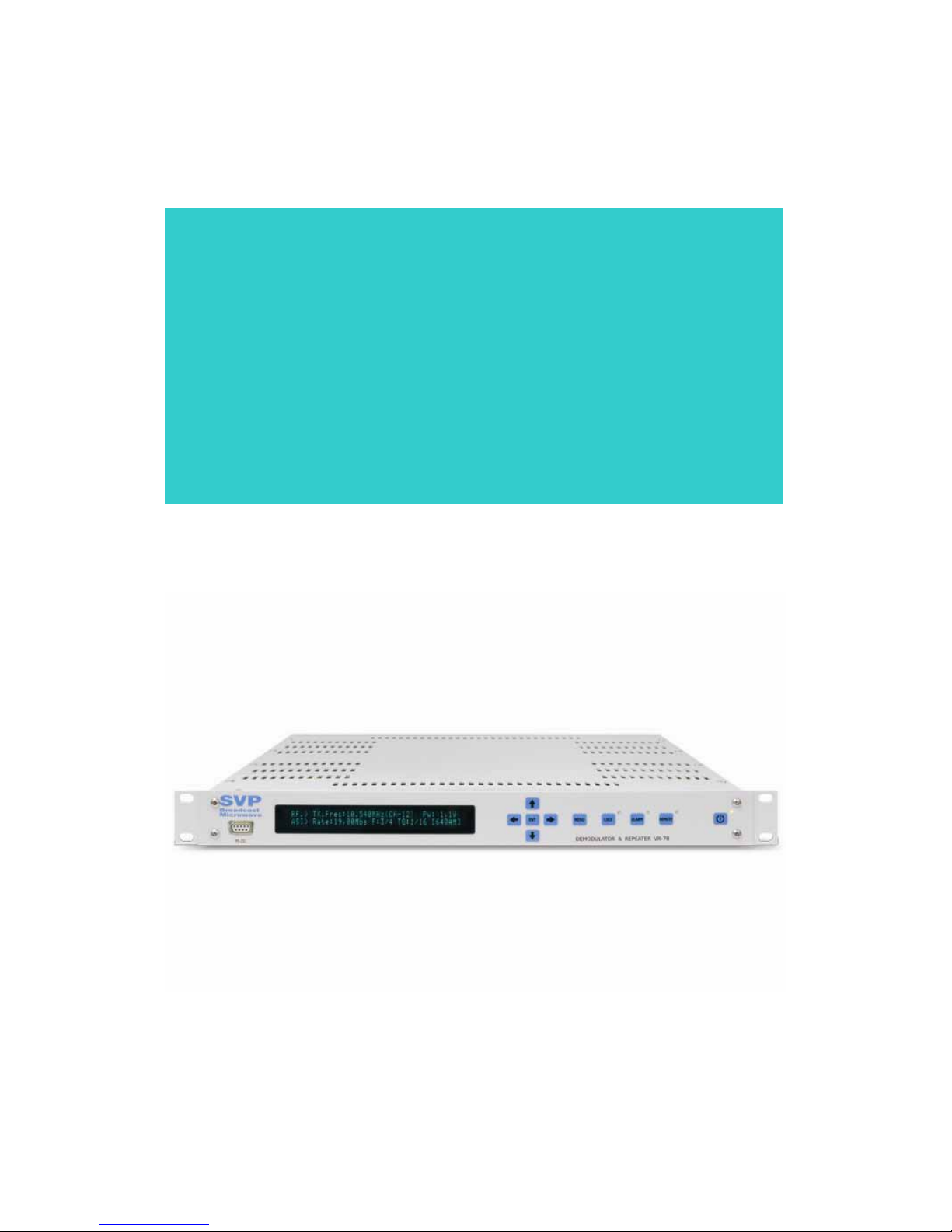
VR-70
Demodulator & Repeater
Page 8

Chapter 1: VT-70 Modulator
VR-70 and DCM User’s Manual Page 8
Contents
1. Theoretical Operation .................................................................... 10
2. Connections ................................................................................. 13
2.1 Power Supply .......................................................................... 13
2.2 Video ...................................................................................... 14
2.3 Audio ..................................................................................... 15
2.4 Up-Converter and Down-Converter ............................................. 15
3. Technical features ......................................................................... 17
3.1 I.F.(Intermediate Frequency) ..................................................... 17
3.2 Video ...................................................................................... 17
3.3 Audio ..................................................................................... 18
3.4 Power Supply .......................................................................... 18
3.5 Consumption ........................................................................... 18
3.6 Physical characteristics ............................................................. 18
3.7 Environmental Conditions .......................................................... 19
4. Front panel control ........................................................................ 20
4.1 Turning on the equipment (POWER ON / OFF) .............................. 20
4.2 Locking the keypad (LOCK) ........................................................ 20
4.3 Remote control (REMOTE) ......................................................... 21
4.3. Alarms (ALARM) ...................................................................... 21
4.4 Menu ...................................................................................... 21
4.5 UP, DOWN, LEFT, RIGHT, ENTER ................................................ 22
5. Rear panel connectors and fuses ..................................................... 23
5.1 AC power supply (POWER AC) .................................................... 23
5.2 AC Fuse (FUSE A.C.) ................................................................. 23
5.3 DC Power input (POWER D.C.) ................................................... 23
5.4 Remote control connector (ETHERNET) ........................................ 23
5.5 Audio 1 output connector (AUDIO 1) ........................................... 23
5.6 Audio 2 output connector (AUDIO 2) ........................................... 24
5.7 Audio3 output connector (AUDIO 3) ............................................ 24
5.8 Audio 4 output connector (AUDIO 4) ........................................... 24
5.9 Video output 1 (VIDEO 1) .......................................................... 24
5.10 Video output 2 (VIDEO 2) ........................................................ 24
5.11 Up-Converter output (UP-CONVERTER) ...................................... 24
5.12 Down-Converter input (DOWN-CONVERTER) .............................. 25
6. Local control of the equipment ........................................................ 26
6.1 Introduction ............................................................................ 26
6.2 Using equipment’s menu ........................................................... 27
6.3 “Monitor Status” Menu .............................................................. 28
6.4 “Setup configuration” menu ....................................................... 30
6.5 Alarms and/or warnings menu ................................................... 35
Page 9

Chapter 1: VT-70 Modulator
VR-70 and DCM User’s Manual Page 9
List of figures
Figure 1.1 VR-70 Receiver’s block diagram ........................................... 12
Figure 2.1 VR-70 demodulator and DCM Down-converter connections ...... 13
Figure 4.1 VR-70 Demodulators ON/OFF button .................................... 20
Figure 4.2 Lock button ...................................................................... 20
Figure 4.3 Remote control button ....................................................... 21
Figure 4.4 ALARM button ................................................................... 21
Figure 4.5 MENU button .................................................................... 21
Figure 4.6 Menu navigation controls .................................................... 22
Figure 5.1 Back view of the rack-mount VR-70 demodulator ................... 25
Figure 6.1 Equipment local control configuration ................................... 26
List of tables
Table 3.1 I.F Input/Output features .................................................... 17
Table 3.2 Video features .................................................................... 17
Table 3.3 Audio Features ................................................................... 18
Table 3.4 Power Supply features ......................................................... 18
Table 3.5 Consumption ..................................................................... 18
Table 3.6 Physical characteristics ........................................................ 18
Table 3.7 Environmental Conditions .................................................... 19
Table 6.1 “Monitor Status” menu ........................................................ 28
Table 6.2 “Setup Configuration” menu ................................................. 31
Page 10

Chapter 1: VT-70 Modulator
VR-70 and DCM User’s Manual Page 10
1. Theoretical Operation
The VR-70 demodulates an Intermediate Frequency (I.F.) signal into a
video and two audio signals. This equipment also allows re-sending the
signal acting as a repeater.
A 70MHz I.F. signal coming from an external down-converter or an external
standard FI signal from another link system is fed into the VR-70. This
equipment demodulates the I.F signal. Besides, connecting an up-converter
is also possible. The VR-70 can re-send the I.F. signal to another node and
there is no need to demodulate it.
Every type SVP up-converters and down-converters, in terms of output
power and frequency, can be used with the VR-70 demodulator and
repeater.
Once fed the IF signal into the VR-70, the signal is filtered by a band-pass
active filter and then, amplified by a logarithmic amplifier. The output
signal obtained after this process has a 0dBm constant level.
The logarithmic amplifiers used provide a linear DC voltage depending on
the signal input level. This signal is visualized in the frontal panel display;
the display is calibrated to show the signal level in dBm.
Afterwards, the amplified signal is fed into a FM demodulator, which the
delivers the base-band signal.
On one hand, the base band signal is inserted into a two subcarrier audio
demodulator, and on the other hand to the video processor.
The audio demodulator has two parts one for each audio channel. On each
audio input, before the demodulator, there are a high-pass filter, and a
colour video band-stop filter, in 4,43MHz.
Then, the audio signal is converted to 10,7MHz. As a local oscillator a
quartz crystal is used. If we want to change the signal’s frequency, the
crystal has to be changed.
Quartz crystal’s frequency has to be:
Quartz crystal’s frequency = Received frequency + 10,7MHz
Afterwards, the signal is FM demodulated and the audio signal is obtained.
Now, the audio signals can be adjusted from the keypad and display in the
front panel.
The output audio signal is balanced and line level. The maximum output
level is +16dBm on 600Ω. The equipment is adjusted to deliver +12dBm
audio signals with a 200 KHz peak to peak deviation.
Page 11

Chapter 1: VT-70 Modulator
VR-70 and DCM User’s Manual Page 11
On the other hand, the demodulated video signal is amplified and filtered
by a 6MHz width low-pass filter, obtaining the video signal that will be
present on the rear panel.
The demodulator has to independent video signal outputs, which will be
useful either to monitor the signal or to connect and fed it to two different
equipments.
In the front panel is displayed whether the received video signal is
synchronized or not. If video signal is not synchronized, the LED next to the
ALARM button lights. From the front panel keypad and display video level
can also be changed.
Besides, the external input signal meter displays the input signal level
which can be very useful while installing and aligning the link antennas. It
also has a video signal detector.
The VR-70 demodulator and repeater can be fed can be fed either by and
AC source between 100 and 240V and 50 to 60Hz frequency or by a 12V
DC source (battery).
The receiver internally generates +10V, -10V and +5V supply voltages
required to fed the different boards of the equipment.
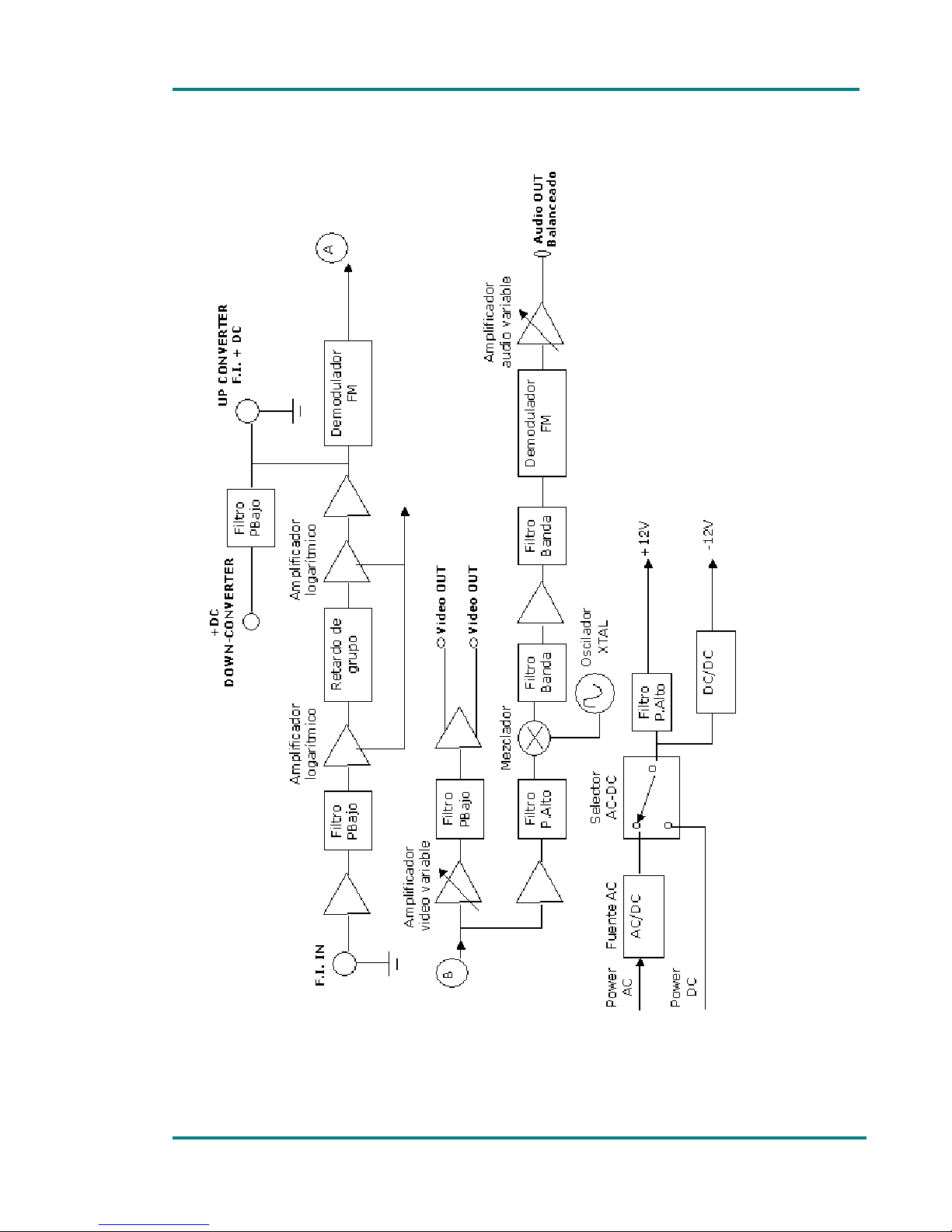
The figure below shows VR-70 receiver’s block diagram:
Page 12
Chapter 1: VT-70 Modulator
VR-70 and DCM User’s Manual Page 12
Figure 1.1 VR-70 Receiver’s block diagram
Page 13
Chapter 1: VT-70 Modulator
VR-70 and DCM User’s Manual Page 13
2. Connections
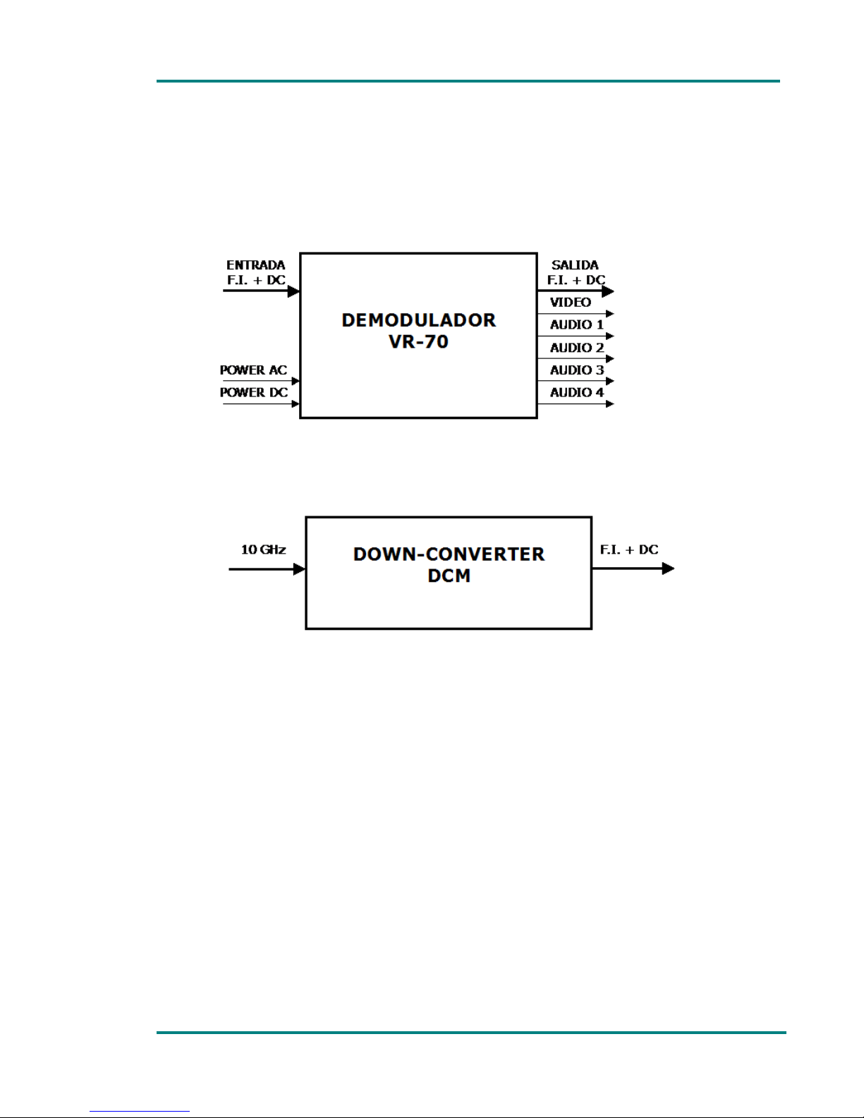
The figure below shows every connection of both, VR-70 demodulator and
DCM up-converter.
Figure 2.1 VR-70 demodulator and DCM Down-converter connections
2.1 Power Supply
The VR-70 modulator can be feed by and AC source between 100 and 240V
or by a DC source of 12 to 14V. The -48V power supply is optional; range
from -36 to -72V.
When the equipment is fed by an AC source, this is connected to a switched
power supply that gives a 12V/4,2A output.
The power-supply board receives either the 12V supply from that power
source or a DC voltage between 12 and 14V from the DC power input.
Then, converts the input to the supply voltages required by the equipment:
+5V, +10V, +12V, -12V and +24V. In this way, the equipment can be fed
by a 12V voltage signal coming from a battery.
The equipment has a power supply that operates when the equipment is
fed with 220V AC to feed all the receiver’s modules. The output current of
Page 14

Chapter 1: VT-70 Modulator
VR-70 and DCM User’s Manual Page 14
this power supply is 4,2Amp to be able to feed any up-converter type
including the most powerful ones, when working as a repeater.
The mains frequency should be between 50 and 60Hz.
The maximum input consumption in 220V is 0,8A.
In the AC input, the equipment has 2 fuses, one external of 2A on the rear
panel and other inside of 3A located in the power supply.
When the equipment is 12V DC input feed, this supply voltage directly
reaches receiver’s every module and it has a 4A fuse in the rear panel.
AC mains input uses a MLC Neutrik connector. The cable required to
connect to the AC main is supplied with the equipment. AC power connector
used in this equipment is designed to prevent accidental disconnection. To
extract the connector, pull back the locking and rotate the connector, as
indicated in the connector itself
The DC power supply is connected via a Neutrik 4-pin male XLR connector
with a safety clip to prevent accidental disconnect.
XLR-4 male connector pinout to connect it to DC power supply
PIN-1: negative
PIN-2: free
PIN-3: -48V (optional)
PIN-4: from +12 to +14V
The equipment is protected from reverse polarity and 15V overvoltage.
It is not advisable to use a power lead with a cross-section smaller than
that of the lead supplied, since this would cause a drop in the supply
voltage and deficient operation of the equipment.
2.2 Video
To connect video signal a 75Ω BNC connectors are used. These connectors
are located on the rear panel and they are labelled as VIDEO OUTPUT 1 and
VIDEO OUTPUT 2. The transmitter input impedance is 75Ω. Both outputs
are equal and independent. If one output is loaded or in short-circuit that
does not have any effect on the other output. Maximum output level is
1Vpp over 75Ω, Standard level.
SVP Broadcast Microwave recommends the use of RG-59 video cable. If this
type is not used, we recommend that the cable used does not attenuate the
high frequencies of the video signal. Once the video cable has been
selected, it is important to determine the length required. For cables longer
than 50m, it is advisable to check the cable and the losses that occur in it
Page 15

Chapter 1: VT-70 Modulator
VR-70 and DCM User’s Manual Page 15
It is important that 75Ω connectors are used. This is because the female
output connector of the VR-70 demodulator unit may be damaged and
because an impedance mismatch will occur.
If the received RF signal does not carry a video signal, the display in the
demodulator unit will display VIDEO: OFF and the led next to the ALARM
button flashes red. This way the user knows that video signal is not been
inserted in the transmitted signal or that there might be a failure in the
video source and/or the connection cables. When input video signal is
detected, the led next to alarm button is switched off (if there are no more
alarms) and in the display appears VIDEO: ON.
2.3 Audio
The equipment is delivered with the output configuration below:
Maximum line level +12dBm, balanced output on 600Ω.
Because the audio signal is balanced, its level is measured between 2
nd
and 3
rd
pins.
The VR-70 has two audio outputs, available on 3-pin male XLR
connectors on the rear panel.
XLR-3 pinout is:
PIN-1: ground
PIN-2: hot (+)
PIN-3: cold (-)
The equipment has an audio meter. To visualize the measurement, the
following option in the menu has to be selected: Monitor Status: Peak Level
Meter. The operation of this audio meter is similar to the operation mode of
a picometer, since it has different integration times for ascendant (fast) and
descendent (slow) slopes. This facility is useful to measure signal peaks,
not the signal level.
2.4 Up-Converter and Down-Converter
To connect the rack-mount VR-70 demodulator unit and the DCM downconverter a low loss 50Ω coaxial cable should be used.
If a RG-214 coaxial cable is used the maximum cable length is 100m. Cable
length can be doubled if celflex cable of ½” is used.
High quality 50Ω N connectors are recommended in cable ends.
Page 16

Chapter 1: VT-70 Modulator
VR-70 and DCM User’s Manual Page 16
The cable delivers a 70MHz signal and the DC supply voltage to feed the
down-converters.
Page 17

Chapter 1: VT-70 Modulator
VR-70 and DCM User’s Manual Page 17
3. Technical features
3.1 I.F.(Intermediate Frequency)
Table 3.1 I.F Input/Output features
Item Feature
Input frequency 70MHz
Input I.F. Level from –60 to +5dBm
Output frequency 70MHz
Output I.F. level +5dBm
Frequency deviation 8MHz pp
Input/output I.F. impedance 50Ω (75Ω optional)
Input/Output I.F. connectors N
Demodulation FM
3.2 Video
Table 3.2 Video features
Item Feature
Video output nº 2
Video connectors BNC
Impedance 75Ω
Video level 1 Vpp on 75Ω
System PAL (NTSC optional)
Video polarity Internally selectable
Signal to Noise ratio >65dB (-40dBm de RF)
Differential gain <1%
Differential phase <1º
Luminance-chrominance delay <10ns
Luminance linearity <1%
Video response 25Hz to 6MHz
Page 18

Chapter 1: VT-70 Modulator
VR-70 and DCM User’s Manual Page 18
3.3 Audio
Table 3.3 Audio Features
Item Feature
Audio channel number 2 (4 optional)
Audio connector XLR-3 macho
Audio output level +13 dBm maximum
Impedance 600Ω balanced
Subcarrier frequency from 5,5 to 9MHz
De-emphasis 50µs
Frequency response +/-1dB from 30 Hz to 15 KHz
Typical distortion <0,4%@1KHz@+12dBm
Signal to noise ratio >70dB
Video Crosstalk >65dB
Demodulation FM
Attenuation in 15,625KHz >15dB
3.4 Power Supply
Table 3.4 Power Supply features
Item Feature
AC power supply voltage 100-240 V. (50/60Hz)
DC power supply voltage 12-14 V. Negative to ground
(-48V. optional, from -36 to -72V)
AC connector Neutrik MLC
DC connector XLR-4 male
3.5 Consumption
Table 3.5 Consumption
Item Feature
AC consumption Depends on the up-converters used.
DC consumption Depends on the up-converters used.
3.6 Physical characteristics
Table 3.6 Physical characteristics
Item Feature
Dimensions 1U rack 19” depth: 360 mm
F.I. cable maximum length RG-214 = 100m
Page 19

Chapter 1: VT-70 Modulator
VR-70 and DCM User’s Manual Page 19
3.7 Environmental Conditions
Table 3.7 Environmental Conditions
Item Feature
Operating temperature range -10ºC to +55ºC
Page 20

Chapter 1: VT-70 Modulator
VR-70 and DCM User’s Manual Page 20
4. Front panel control
4.1 Turning on the equipment (POWER ON / OFF)
To turn the equipment on and off, keep this button pressed for several
seconds. When the equipment is turned on, the display will show the startup message (model and version of the equipment) for a few seconds, and
then it will display the status of the equipment (reception frequency and
reception level and transmission frequency and transmission power). This
on/off button works regardless of whether DC or AC power is used.
If the power fails while the equipment is operating, it will restart
automatically when the power returns, without being necessary to press the
on/off button again.
Figure 4.1 VR-70 Demodulators ON/OFF button
The LED next to this button indicates when the equipment is turned on.
The LED lights up in green when the equipment is turned on.
The LED flashes red when there is power into the equipment but it is
turned off.
4.2 Locking the keypad (LOCK)
This button is used to lock and unlock the keypad. When the keypad is
locked, the LED next to this button lights up in green, and stays lit until this
button is pressed again to unlock the keypad.
The purpose of this button is to prevent unwanted manipulation of the
equipment (unwanted changes to the configuration, etc).
Figure 4.2 Lock button
Page 21
Chapter 1: VT-70 Modulator
VR-70 and DCM User’s Manual Page 21
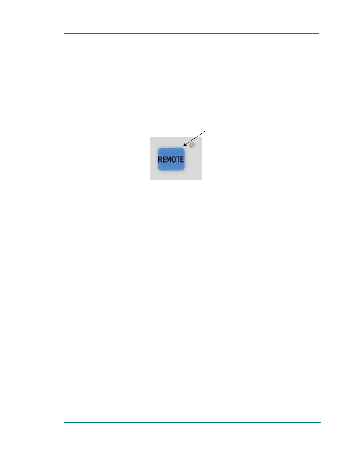
4.3 Remote control (REMOTE)
This button is used to activate the remote control mode. When the LED
next to this button is lit green, the equipment is ready for being controlled
remotely via the Ethernet link. To activate or defuse the remote control,
simply press this button. If the equipment is configured to be controlled
remotely, the keypad orders are rejected.
Figure 4.3 Remote control button
4.3. Alarms (ALARM)
When the equipment detects the existence of one or more alarms, the
corresponding LED lights in red, and when one or more warnings are
detected, de LED lights in orange. When the ALARM button is pressed, the
equipment displays the alarms and/or warnings it has detected. To exit the
alarm menu and return to the main menu, simply press the ALARM button
again.
Figure 4.4 ALARM button
4.4 Menu
This button is used to enter and exit the equipment control menu and
submenus.
Figure 4.5 MENU button
Page 22

Chapter 1: VT-70 Modulator
VR-70 and DCM User’s Manual Page 22
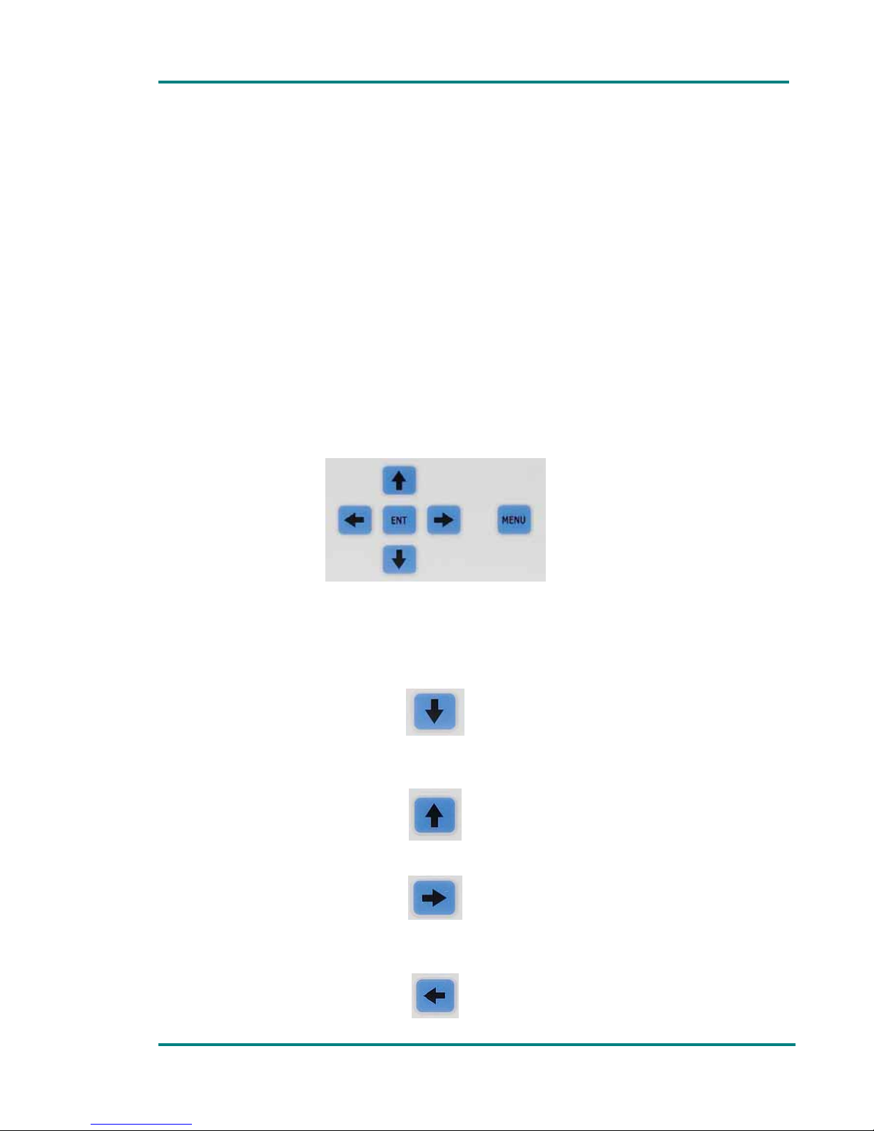
4.5 UP, DOWN, LEFT, RIGHT, ENTER
The arrow buttons and the ENT (Enter) button are used to navigate through
the menus.
Figure 4.6 Menu navigation controls
For more details regarding local control of the equipment, see section 6.1 of
this manual.
Page 23

Chapter 1: VT-70 Modulator
VR-70 and DCM User’s Manual Page 23
5. Rear panel connectors and fuses
5.1 AC power supply (POWER AC)
To connect the equipment to AC main an MCL Neutrik connector is used. It
is recommended to use the cable supplied with the equipment.
The AC power connector used in this equipment is designed to prevent
accidental disconnection. To extract the connector, pull back the locking clip
and rotate the connector, as indicated on the connector itself.
5.2 AC Fuse (FUSE A.C.)
The AC input safety fuse is used as high surge voltage and short-circuit
protection.
5.3 DC Power input (POWER D.C.)
The DC power supply is connected via a Neutrik 4-pin male XLR connector
with a safety clip to prevent accidental disconnection.
The pinout is:
Pin 1= ground
Pin 3= -48V (optional)
Pin 4 = +12 to +14V
5.4 Remote control connector (ETHERNET)
This connector is use to connect the equipment to an Ethernet local area
network, so that the equipment can be controlled remotely.
5.5 Audio 1 output connector (AUDIO 1)
Balanced audio output connector is an XLR-3 male.
The pinout of the audio connector is:
Pin 1: ground
Pins 2 and 3: signals
Page 24

Chapter 1: VT-70 Modulator
VR-70 and DCM User’s Manual Page 24
5.6 Audio 2 output connector (AUDIO 2)
Balanced audio output connector is an XLR-3 male.
The pinout of the audio connector is:
Pin 1: ground
Pins 2 and 3: signals
5.7 Audio3 output connector (AUDIO 3)
Balanced audio output connector is an XLR-3 male.
The pinout of the audio connector is:
Pin 1: ground
Pins 2 and 3: signals
5.8 Audio 4 output connector (AUDIO 4)
Balanced audio output connector is an XLR-3 male.
The pinout of the audio connector is:
Pin 1: ground
Pins 2 and 3: signals
5.9 Video output 1 (VIDEO 1)
The output video connector is 75Ω BNC type. The output signal standard
level is 1Vpp.
5.10 Video output 2 (VIDEO 2)
The output video connector is 75Ω BNC type. The output signal standard
level is 1Vpp.
5.11 Up-Converter output (UP-CONVERTER)
N type connector is used to connect an up-converter so that the VR-70
works as a repeater, no demodulating the signal.
Page 25
Chapter 1: VT-70 Modulator
VR-70 and DCM User’s Manual Page 25
5.12 Down-Converter input (DOWN-CONVERTER)
N type connectors are used to connect the down-converter.
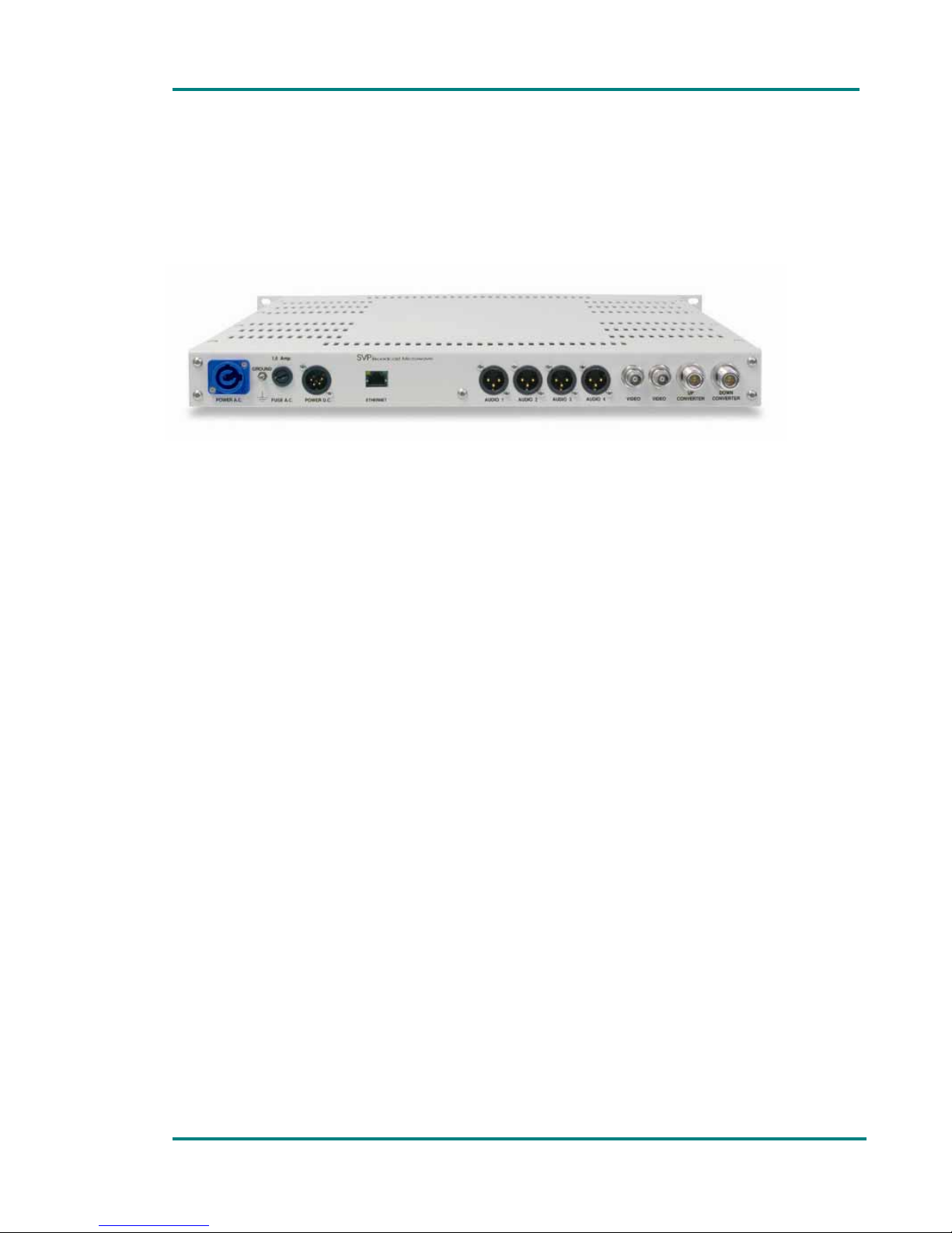
In the figure below the rear panel of the VR-70 demodulator is shown.
Figure 5.1 Back view of the rack-mount VR-70 demodulator
Page 26
Chapter 1: VT-70 Modulator
VR-70 and DCM User’s Manual Page 26
6. Local control of the equipment
6.1 Introduction
The VR-70 demodulator can be configured, controlled and monitored either
locally or remotely (via an Ethernet LAN connection).
To enable the user to control the equipment locally (using the keypad and
the display in the front panel), the LED next to REMOTE button has to be
out; otherwise the equipment can only be controlled in a remote way.
Figure 6.1 Equipment local control configuration
The display in the front panel visualizes the following parameters:
Reception frequency (MHz)
Received signal level in the antenna (dBm)
Transmission frequency (MHz)
Transmission power in the antenna (Watt)
Those are the parameters displayed when the equipment is not being
operated by the user to configure or monitor the received signal.
When the VR-70 equipment does not detect the down-converter connected
to it the display will show Down-Converter:<<Not present>> and neither
frequency nor received signal level will be displayed in the main screen.
This can happen in the following situations:
The down-converter is not correctly connected to the demodulator.
The I.F. cable that matches the down-converter and the demodulator is
not in good condition.
The power supply to the down-converter is disabled in the demodulator.
The power supply to the down-converter is not enough to feed it.
The same happens when the VR-70 equipment does no detect the upconverter. The display in the VR-70 will show: Up-converter: <<Not
present>>.
LED out
Page 27
Chapter 1: VT-70 Modulator
VR-70 and DCM User’s Manual Page 27
This can happen because:
The up-converter is not correctly connected to the demodulator.
The I.F. cable that matches the up-converter and the demodulator is not
in good condition.
The power supply to the up-converter is disabled in the VR-70.
The power supply of the VR-70 to feed the up-converter is not enough.
When the user stops manipulating the equipment (when several seconds
have passed since the last order), the display’s luminosity is reduced to
save energy.
6.2 Using equipment’s menu
To enter the menu, press the MENU button on the front panel. Once in the
menu, the user can navigate through it with the arrow buttons and the ENT
button. To exit the menu and return to the main screen, simply press the
MENU button again.
Figure 6.2 Equipments Keypad
The function of each button in figure 6.2 is explained below in detail.
DOWN: moves to the next option in the current menu, and also has
other specific functions.
• UP: moves to the previous option in the current menu, and also has
other specific functions.
• RIGHT: used for specific functions.
• LEFT: used for specific functions.
Page 28

Chapter 1: VT-70 Modulator
VR-70 and DCM User’s Manual Page 28
• ENT: This button has several functions. It is used to enter submenus
1
,
to select an option when there are several choices and for other specific
functions.
6.3 “Monitor Status” Menu
The monitor status menu is used to monitor the status of different
parameters of the VR-70 modulator, the DCM down-converter and UCM upconverter. It can not be used to configure these parameters.
This section contains a detailed description of all the parameters that can
be monitored or displayed with the MONITOR STATUS menu of the VR-70
demodulator.
To enter this menu, press the MENU button, use the UP and DOWN buttons
to select the MONITOR STATUS menu, and then press the ENT button.
In the first line of the MONITOR STATUS menu the equipment model (VR70 in this case), the serial number and the software version are displayed.
The UP and DOWN buttons are used to navigate through the menu options.
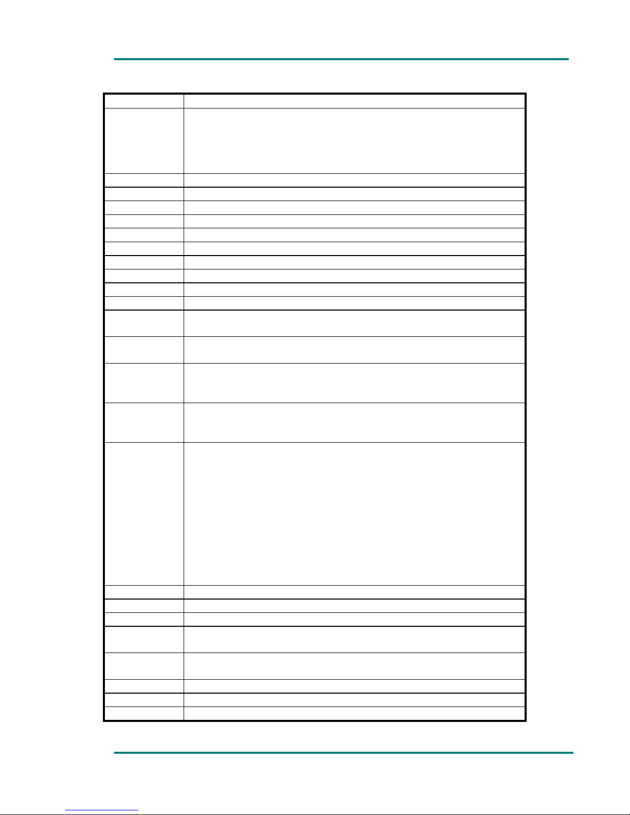
The table below shows the different options in the MONITOR STATUS
menu:
Table 6.1 “Monitor Status” menu
Line no. Function
1 Model, serial no. and software version.
2
The location of the equipment and source and destination
nodes of the link. Press ENT key to enter a submenu that
displays the location of the equipment and the locations of
the source and destination nodes of the communication
link.
3
Reception frequency in MHz.
When the frequency is configured manually, using the
channel selector in the up converter, the VR-70 displays
the channel number and the reception frequency preceded
by blinking MN characters.
If the frequency is configured from the SETUP
CONFIGURATION menu (channel selector set to 0 in the
down-converter), the equipment displays the reception
frequency and the label slave in brackets. Consequently the
down-converter is configured from the VR-70 demodulator.
1
The existence of a submenu is indicated on the display with the ENTER symbol
Page 29
Chapter 1: VT-70 Modulator
VR-70 and DCM User’s Manual Page 29
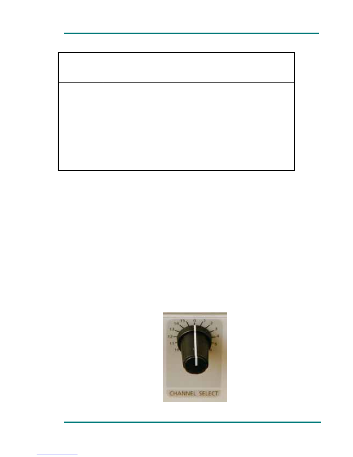
Line no. Function
4
Received signal level (dBm) on the antenna. Besides, if ENT
button is pressed to enter the menu, a graphic bar is
displayed, which shows the current signal level and the
maximum signal level received. This can be very useful to
position the receiver antenna.
5 SAW filter ENABLED/DISABLED
6 Video polarity (positive or negative).
7 Video level (%)
8 Audio 1 level (dBm)
9 Audio 2 level (dBm)
10 Audio 3 level (dBm)
11 Audio 4 level (dBm)
12 Temperature of the DCM Down-converter
13 DC supply voltage in the down-converter
14 Video signal presence/absence
15
DC power supply to the down-converter enabled or
disabled (ENABLE or DISABLE).
16
Status of the PLL in the down-converter, LOCKed or
UNLOCKed.
17
Mute ENABLED/DISABLED. If the received signal level is
lower than the level in the 18th line of this menu the
equipments triggers the Mute.
18
Mute level (dBm). For values of received signal level lower
than his the Mute is triggered. This value can be defined in
the “Setup Configuration” menu.
19
Transmission frequency in MHz.
When the frequency is manually configured by the channel
selector in the UCM up converter, the VR-70 displays the
channel number and the transmission frequency preceded
by blinking MN characters.
If the frequency is configured from the SETUP
CONFIGURATION menu (channel selector set to 0 in the
up-converter), the equipment displays the transmission
frequency in MHz and the label slave in brackets.
Consequently the up-converter is configured from the VR-
70 demodulator.
20 Signal transmission power set in the antenna (Watt)
21 Temperature in the UCM up-converter
22 Power supply voltage in the UCM up-converter
23
DC power supply to the up-converter enabled or disabled
(ENABLE or DISABLE).
24
Status of the PLL in the up-converter, LOCKed or
UNLOCKed
25 Temperature in the VR-70 demodulator
26 VR-70 power supply voltage
27 VR-70 power source (AC or DC)
Page 30
Chapter 1: VT-70 Modulator
VR-70 and DCM User’s Manual Page 30
28
Ethernet configuration parameters. (port, local and remote
IP addressed)
29
Date and time. The demodulator always shows current date
and time.
30
List of alarms and/or warnings that have been detected.
When the equipment indicates the existence of an alarm
(the LED lights in red) or of a warning (the LED lights in
orange), the user can view the alarms/warnings by simply
pressing the ALARM button or using the MONITOR STATUS
menu. To view the alarms/warnings move to the line 30
using UP and DOWN buttons, then press the ENT button to
enter the “Alarms and Warnings List” submenu. If there are
no alarms or warnings, the LED next to alarm button will be
out, and if the user presses the ALARM button or accesses
the “Alarms and Warnings List” submenu, the unit displays
“No alarms” and “No warnings”.
To exit any submenu, press the MENU button.
If the user does no press any button during several minutes, the VR-70
demodulator will automatically exit the menu or submenu it was left in and
displays the main screen (in one hand reception power and frequency and
on the other hand, transmission power and frequency).
6.4 “Setup configuration” menu
Several parameters of the VR-70 demodulator, DCM down-converter and
UCM up-converter can be configured from the VR-70 demodulators SETUP
CONFIGURATION menu.
To be able to change parameters in the down-converter and the upconverter via the demodulator, the channel selector in both equipments has
to be in 0 position.
Figure 6.3 Channel selectors in 0 position to control the down-converter
and up-converter parameters from the VR-70 demodulator.
Page 31
Chapter 1: VT-70 Modulator
VR-70 and DCM User’s Manual Page 31
This section contains a detailed description of each of the parameters that
can be configured in the VR-70 demodulator and repeater.
To enter the SETUP CONFIGURATION menu, press the MENU button, use
UP and DOWN buttons to select the SETUP CONFIGURATION menu, then
press ENT button again.
To navigate through the menu and configure the different parameters, use
the UP, DOWN, LEFT, RIGHT and ENT buttons.
The table below shows the different lines/options in the SETUP
CONFIGURATION menu.
Table 6.2 “Setup Configuration” menu
Line no. Function
1 Reception frequency in the down-converter. This
parameter is only configurable from the VR-70 when the
channel selector in the DCM down-converter is set to 0.
Otherwise, reception frequency is set by the channel
selector in the up-converter.
2 SAW filter enable or disable (ON/OFF)
3 Video polarity (positive or negative)
4 Mute enable or disable. (ENABLE/DISABLE)
5 Mute level. If the received signal level is lower than the
one set here, the mute is triggered
6 Enable/disable power supply through I.F. cable to the
down-converter.
7 Up-converter transmission frequency. It can only be
configured from the VR-70 modulator when the channel
selector is set to 0 in the UCM up-converter. Otherwise,
transmission frequency is set by the channel selector in
the up-converter.
8 Video level (%)
9 Audio 1 level (dBm)
10 Audio 2 level (dBm)
11 Audio 3 level (dBm)
12 Audio 4 level (dBm)
13 Enable/disable power supply through I.F. cable to the up-
converter
14 Location of the equipment and source and destination
nodes of the link. To configure this press ENT button and
a submenu in which equipment location, source and
destination nodes can be configured displayed.
15 Ethernet configuration parameters (port, local and
remote addresses)
16 Current date and time configuration
Page 32

Chapter 1: VT-70 Modulator
VR-70 and DCM User’s Manual Page 32
The steps required to configure each of the parameters listed in this table
will be explained in detail below.
Reception frequency
To configure reception frequency in the DCM down-converter via VR-70
demodulator, the channel selector in the DCM down-converter has to be in
0 position. Next, move to line 1 in the SETUP CONFIGURATION menu using
UP and DOWN buttons, then press the ENT button. When this button is
pressed, the cursor will be placed over the first digit, which can be changed
by pressing the UP and DOWN buttons. To change the other digits, press
the LEFT and RIGHT buttons until the cursor is over the digit to be changed.
When the desired frequency has been set, press the ENT button and the
equipment will be locked onto that frequency.
The transmission frequency can be configured with 1 MHz resolution. If the
user tries to set a transmission frequency lower than 10.200MHz the downconverter is locked to the minimum possible frequency, 10.200MHz. The
same happens for the maximum accepted frequency. If the user tries to set
a reception frequency higher than 10.600MHz the down-converter will be
locked to the maximum possible frequency, 10.600MHz.
SAW filter
To enable or disable this filter, SAW filter, move to the line number 2 on the
setup configuration menu using UP and DOWN buttons. Pressing ENT button
the estate of the SAW filter is changed, form enabled (ON) to disabled
(OFF) and the other way around.
Video polarity
To configure video polarity, move to line 3 in the SETUP CONFIGURATION
menu using the UP and DOWN arrows, then press ENT button. By pressing
ENT button video polarity is changed from positive to negative and vice
versa.
Mute enable/disable
To change mute status, move to line 4 using UP and DOWN arrows. . By
pressing ENT button Mute status is changed from enabled (ON) to disabled
(OFF) and vice versa.
Mute level
To set the mute level, from which if the received signal level is lower than
that value, the mute is triggered, move to line 5 using UP and DOWN
buttons and press ENT. Next, using LEFT and RIGHT arrows increase or
decrease the value (in dB).
Page 33

Chapter 1: VT-70 Modulator
VR-70 and DCM User’s Manual Page 33
DCM Down-converter power supply
To enable or disable power supply to the down-converter, move to line 6 in
the SETUP CONFIGURATION menu using the UP and DOWN arrows. Then
press ENT button to enable or disable the power-supply to feed the downconverter through the IF coaxial cable.
Transmission frequency
To configure transmission frequency in the UCM up-converter via VR-70
demodulator, channel selector in the UCM up-converter has to be in 0
position. Next, move to line 7 in the SETUP CONFIGURATION menu using
UP and DOWN buttons, then press the ENT button. When this button is
pressed, the cursor will be placed over the first digit, which can be changed
by pressing the UP and DOWN buttons. To change other digits, press the
LEFT and RIGHT buttons until the cursor is over the digit to be changed.
When the desired frequency has been set, press the ENT button and the
equipment will be locked onto that frequency.
The transmission frequency can be configured with 1 MHz resolution. If the
user tries to set a transmission frequency lower than 10.200MHz the upconverter is locked to the minimum possible frequency, 10.200MHz. The
same happens for the maximum accepted frequency. If the user tries to set
a transmission frequency higher than 10.600MHz the up-converter is locked
to the maximum possible frequency, 10.600MHz.
Video level
To configure video level, move to line 8 in the setup configuration menu
using UP and DOWN arrows. Enter the submenu pressing ENT button and a
graphic bar will appear. Using RIGHT and LEFT arrows video level (%) will
be increased or decreased respectively.
Audio 1 level
To set audio level, move to line 9 using UP and DOWN arrows. Enter the
submenu pressing ENT button and a graphic bar will appear. Using RIGHT
and LEFT arrows audio 1 level will be increased or decreased (in steps of
one dB) respectively.
Audio 2 level
To set audio level, move to line 10 using UP and DOWN arrows. Enter the
submenu pressing ENT button and a graphic bar will appear. Using RIGHT
and LEFT arrows audio 1 level will be increased or decreased (in steps of
one dB) respectively.
Audio 3 level
To set audio level, move to line11 using UP and DOWN arrows. Enter the
submenu pressing ENT button and a graphic bar will appear. Using RIGHT
Page 34

Chapter 1: VT-70 Modulator
VR-70 and DCM User’s Manual Page 34
and LEFT arrows audio 1 level will be increased or decreased (in steps of
one dB) respectively.
Audio 4 level
To set audio level, move to line 12 using UP and DOWN arrows. Enter the
submenu pressing ENT button and a graphic bar will appear. Using RIGHT
and LEFT arrows audio 1 level will be increased or decreased (in steps of
one dB) respectively.
UCM Up-converter power supply
To enable or disable power supply to the up-converter, move to line 13 in
the SETUP CONFIGURATION menu using the UP and DOWN arrows. Then
press ENT button to enable or disable the power-supply to the up-converter
through the IF coaxial cable.
Location of the equipment and source and destination nodes.
To configure the location of the equipment and the source and destination
nodes, move to line 14 in the SETUP CONFIGURATION menu using the UP
and DOWN buttons, then press the ENT button to enter the corresponding
submenu. In this submenu the following locations can be configured:
• Location of the VR-70 demodulator: pressing the ENT button, the
cursor will be placed over the first letter. The UP and DOWN arrows
will change the character in alphabetical order. To change to other
characters, press the LEFT and RIGHT buttons until the cursor is over
the character to be changed.
• Location of the source and destination nodes of the link: to configure
the source and destination nodes of the link, press the ENT button
several times until the cursor is located over the first letter after the
FROM or TO labels. To set locations, follow the same procedure as for
the location of the equipment.
When all of the parameters related to the location, and source and
destination nodes of the equipment have been set, press MENU button to
confirm the settings, then press the MENU button again to exit the
submenu.
Ethernet communication parameters
To configure the communications port and the local and remote IP
addresses, move to line 15 in the SETUP CONFIGURATION menu using the
UP and DOWN buttons, then press the ENT button to enter the
corresponding menu.
The following parameters can be configured in this submenu:
Page 35

Chapter 1: VT-70 Modulator
VR-70 and DCM User’s Manual Page 35
• The communications port to be used for communication between the
transmitter and the remote station. Press ENT button and the cursor
will be placed over the first digit, which can be changed by pressing
UP and DOWN arrows. To change to other digits, press LEFT and
RIGHT buttons until de cursor is over the digit to be changed.
• Local and Remote IP addresses: to set the local and remote IP
addresses press the ENT button several times until de cursor is over
the first digit after IPL or IPR label respectively. To set local and
remote IP addresses, follow the same procedure as to set the
communications port.
When all of the parameters related to the location, and source and
destination nodes of the equipment have been set, press MENU button to
confirm the settings, then press the MENU button again to exit the
submenu.
Date and time
To configure current date and time move to line 16 in the SETUP
CONFIGURATION menu using the UP and DOWN buttons. Once on this line,
simply press the ENT button to place the cursor over the first digit of the
time. Use the UP and DOWN arrows to change the digit. To change to other
digits in the time and the date, select them using the LEFT and RIGHT
arrows, then change them with the UP and DOWN buttons. Once the date
has been set, the equipment will automatically display the first three
characters of the day of the week.
In addition, the equipment automatically changes to summer time and
winter time and includes de 29
th
of February in leap years.
To exit each menu and submenu, press MENU button.
6.5 Alarms and/or warnings menu
The VT-70 modulator constantly indicates the existence of alarms and/or
warnings via the LED next to the ALARM button.
If this LED is out, there are no active alarms and warnings.
If this LED lights in orange, the equipment indicates that there are one
of more warnings.
If this LED lights in red, the equipment has one or more alarms,
although there may also be some warnings.
Page 36

Chapter 1: VT-70 Modulator
VR-70 and DCM User’s Manual Page 36
There are two methods to determine which alarms/warnings have been
activated.
The ALARM button: when this button is pressed, the equipment displays
a list of the active alarms and/or warnings. If there are no active alarms
or warnings, the unit displays “No alarms” and “No warnings”.
The MONITOR STATUS menu: the list of active alarms and warnings can
also be viewed via the MONITOR STATUS menu. To do this move to line
17 in the menu using UP and DOWN buttons, then press ENT button to
enter the “Alarms and Warnings List” submenu. As before, if there are
no active alarms or warnings the unit displays “No alarms” and “No
warnings”.
The parameters that can cause alarms and warnings to be activated are
listed below.
Parameters that can cause alarms
VR-70de modulator temperature: if the temperature inside the rack-
mount unit reaches or exceeds 80ºC, an alarm is triggered and the red
LED next to the ALARM button lights. When the temperature drops to
75ºC, the alarm is cancelled.
Power supply voltage of the equipment: if the power supply voltage to
the modulator unit is below 11V, an alarm is triggered and the led next
to alarm button lights red. When the power supply voltage reaches 12V
the alarm is cancelled.
Mute Enabled: if mute signal is enabled, the equipments shows an
alarm, and the LED next to the alarm button lights red.
Communication failure between VR-70 demodulator and DCM down-
converter: When the VR-70 modulator detects a communication failure
with DCM down-converter, the LED next to ALARM button lights red. If
the down-converter is disabled the VR-70 does not show any alarm.
Down-converter temperature: if the temperature inside the down-
converter reaches or exceeds 75ºC, an alarm is triggered and the red
LED next to the ALARM button lights. When the temperature drops to
70ºC, the alarm is cancelled
Low power supply to the down-converter.
Lock status of the down-converter: if the PLL of the down-converter is
not locked in frequency, the equipment shows an alarm and the LED
next to alarm button lights.
Page 37

Chapter 1: VT-70 Modulator
VR-70 and DCM User’s Manual Page 37
Communication failure between VR-70 demodulator and UCM up-
converter. When the VR-70 demodulator detects a communication
failure with the UCM up-converter, the LED next to ALARM button lights
red. If the up-converter is disabled the VT-70 does not show any alarm.
UCM up-converter transmission power: when the transmission power is
equal to or lower than 50% of the maximum transmission power, the
equipment shows an alarm, the LED next to ALARM button lights red.
When the power reaches 55% of the maximum transmission power the
alarm is cancelled.
Maximum transmission power depends on the up-converter used.
Up-converter temperature: if the temperature inside the up-converter
reaches or exceeds 75ºC, an alarm is triggered and the red LED next to
the ALARM button lights. When the temperature drops to 70ºC, the
alarm is cancelled
Low power supply to the up-converter.
Lock status of the up-converter: if the PLL of the up-converter is not
locked in frequency, the equipment shows an alarm and the LED next to
alarm button lights.
Parameters that can cause warnings
VR-70 modulator using battery power (Rack Battery Working): if the
equipment is only receiving battery power, it displays a warning, and
the LED next to the Alarm button lights in orange
Received signal level. If the received signal level in the RF input is lower
than -70dBm, the TR-70 displays a warning and the LED next to the
Alarm button lights in orange.
Page 38
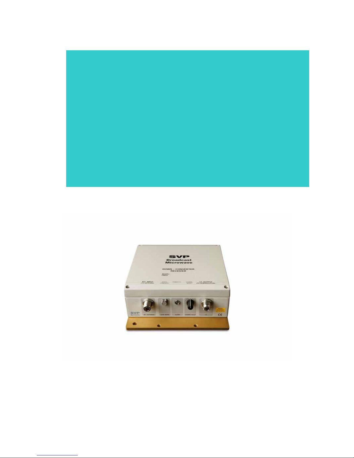
Chapter 2
Multi-frequency
Down-Converter
DCM-1070 series
Page 39

Chapter 2: Multi-frequency Down-Converter DCM-0270, DCM-0770 & DCM-1070 series
VR-70 & DCM User’s Manual Page 39
Contents
1. Theoretical operation..................................................................... 41
2. Technical features ......................................................................... 44
2.1 RF section ............................................................................... 44
2.2 Power supply ........................................................................... 44
2.3 Consumption ........................................................................... 44
2.4 Physical characteristics ............................................................. 44
2.5 Environmental conditions .......................................................... 45
List of figures
Figure 2.1 Down-converter with the external meter .... ¡Error! Marcador no
definido.
List of tables
Table 1.1 Programmed frequency list, 15 channel default frequency
configuration for the UCM 7010 up-converter ....................................... 41
Table 2.1 DCM 1070 RF features ......................................................... 44
Table 2.2 Power supply features ......................................................... 44
Table 2.3 Consumption ..................................................................... 44
Table 2.4 Physical characteristics ........................................................ 44
Table 2.5 Environmental conditions ..................................................... 45
Table 2.1 Technical features ............................................................... 66
Page 40
Chapter 2: Multi-frequency Down-Converter DCM-0270, DCM-0770 & DCM-1070 series
VR-70 & DCM User’s Manual Page 40
IMPORTANT: Input signals higher than -20dBm can damage the equipment.
Page 41
Chapter 2: Multi-frequency Down-Converter DCM-0270, DCM-0770 & DCM-1070 series
VR-70 & DCM User’s Manual Page 41
1. Theoretical operation
The DCM-1070 series multi-frequency down-converter, transform the
received signal within the down-converter band, 10.2 to 10.6GHz to a
70MHz Intermediate frequency
These down-converters are weatherproof, suitable for outdoor work. They
are installed next to the receiving parabolic antenna. The equipment is
watertight and resistant to corrosive and marine environments.
This is a multi-frequency equipment with 15 programmable channels. The
following table shows the default frequency configuration for the DCM-
1070.
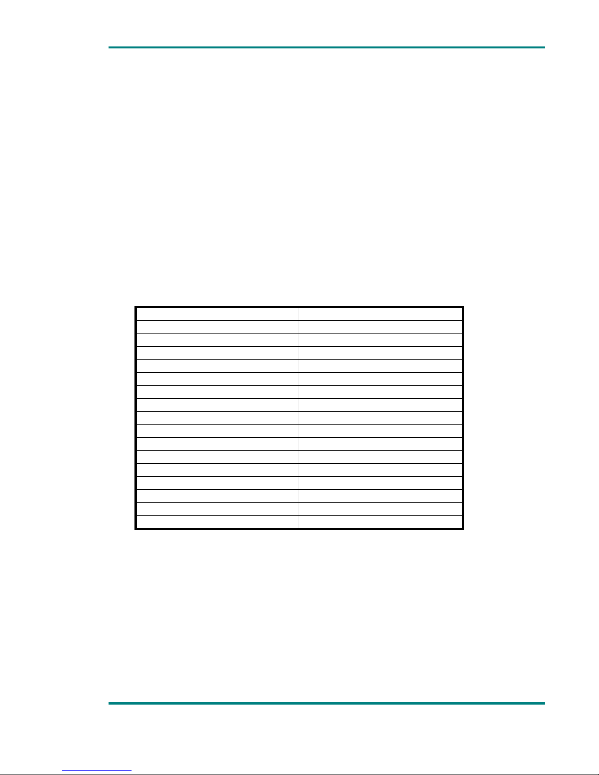
Table 1.1 Programmed frequency list, 15 channel default frequency
configuration for the UCM 7010 up-converter
Channel CH Frequency (MHz)
0 Slave mode
1 10.211
2 10.239
3 10.267
4 10.295
5 10.323
6 10.351
7 10.379
8 10.407
9 10.435
10 10.463
11 10.491
12 10.519
13 10.553
14 10.580
15 10.585
Input frequency can be set manually, using the channel selector in the DCM
down-converter (selecting one of the 15 frequencies previously
programmed) or remotely from VR-70 demodulator and repeater (sending
data to configure the DCM down-converter through the data channel, IF
coaxial cable).
To configure the reception frequency from the VR-70 demodulator’s SETUP
CONFIGURATION menu, the channel selector of the down-converter has to
be in 0 position.
Thanks to the data channel between the up-converter the VR-70
demodulator and repeater, several parameters of the DCM down-converter,
Page 42

Chapter 2: Multi-frequency Down-Converter DCM-0270, DCM-0770 & DCM-1070 series
VR-70 & DCM User’s Manual Page 42
as reception frequency, received signal level in the antenna, the downconverter’s feeding voltage and down-converter’s temperature, can be
visualized in the VR-70 demodulator and repeater display.
Both, the 70MHz FI output of the down-converter (also power supply) and
the RF frequency input connector are N type connectors
The signal is sent from the antenna to the down-converter through a
special low loss cable.
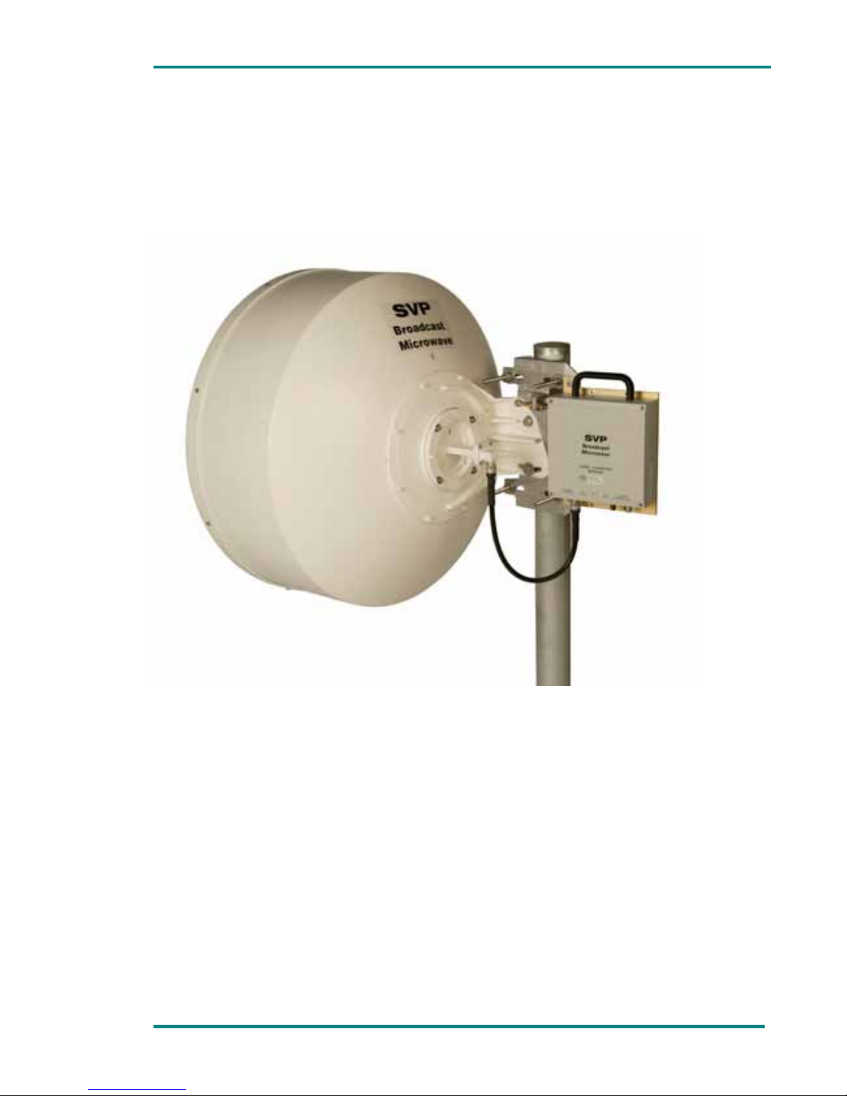
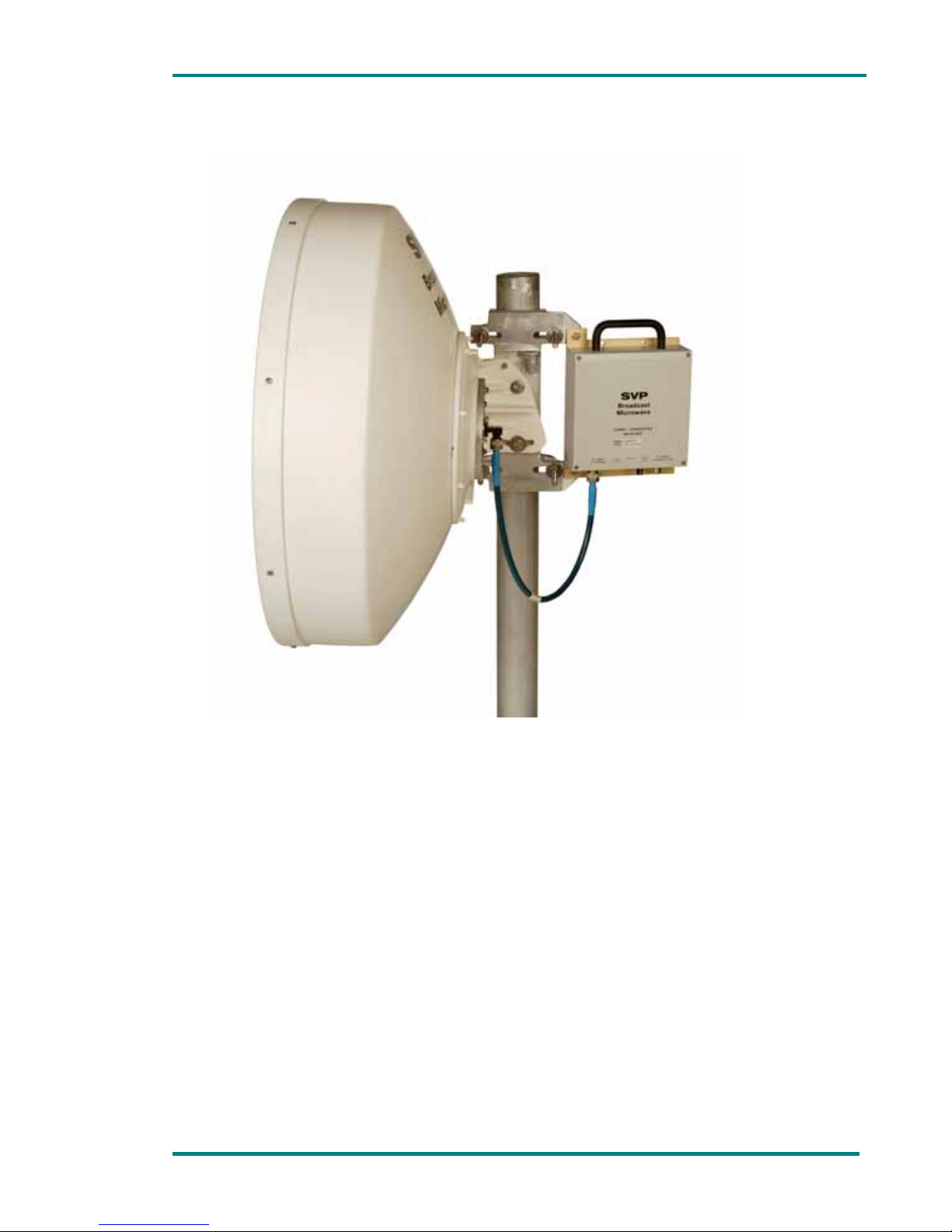
Every down-converter model can be directly installed on the SVP antenna.
This way the complete system, down-converter and antenna, is compact,
robust and easy to install.
DCM down-converters can be used with DR-70 demodulator and repeater
and with RP-70 repeaters
A LED indicates the operation status of the up-converter.
When everything is correct, the LED lights green
When the input signal level is higher than -50dBm the LED blinks green.
If the received signal level is between -50 and -75dBm the led blinks
orange. If the received signal level is lower than -75dBm the LED blinks
red. Besides, the faster the blinking speed the higher the received signal
level. So, just having a look the optimum received signal level can be
detected and it can be useful when pointing the parabolic antenna.
If the LED is out, it can happen that either there is short-circuit or a cut
in the coaxial cable or that the power supply is disabled in the VR-70
demodulator.
If the PLL is unlocked in frequency, the LED blinks red and green
alternatively.
If the down-converter is alarmed because of power supply, temperature
or low received signal level the led blinks red.
The DCM up-converter has a LEMO connector to connect the MD-70
external meter. The user can have exact measurements of the received
signal level, received signal frequency, supply voltage and DCM downconverter’s temperature.
The down-converter operation mode is the following: Firstly, the signal
delivered by the receiver antenna is filtered by a 400MHz width filter.
Afterwards that signal is amplified by three amplifier stages, with a very
low noise figure. Then, the signal is filtered and delivered to a mixer. The
signal is then mixed with another signal coming from a synthesized local
oscillator.
This synthesized local oscillator consists of a low phase noise VCO and is
synthesized by a high performance PLL controlled by a microcontroller. The
signal of the local oscillator (2.3 GHz) is multiplied x4 b to obtain the 9GHz
signal needed for the first conversion.
Page 43

Chapter 2: Multi-frequency Down-Converter DCM-0270, DCM-0770 & DCM-1070 series
VR-70 & DCM User’s Manual Page 43
On the microcontroller 15 channel frequencies are stored. The downconverter has a 16 position watertight channel selector (switch). To change
the 15 frequencies distribution down-converter’s cover has to be removed
and the 16F84 microcontroller model has to be changed.
Next, the signal is filtered and delivered to a second mixer. This second
mixer receives a signal of 704 MHz from local oscillator that consists of a
frequency resonator. The result of this second mix is a 70MHz signal that is
then filtered and put in the 70MHz output I.F. connector.
The power supply voltage from the VR-70 demodulator is removed from the
I.F. output using a choke power coil.
The received signal goes through a logarithmic amplifier and the output
continuous voltage allows us to know the RSSI level. This RSSI makes
possible the control of the signal meter LED.
The equipment has a power supply board that obtains +5, +10and 24V
from the 12DC voltage to feed every part the down-converter. Besides, a
negative -4V voltage is generated to polarize the transistors.
Page 44
Chapter 2: Multi-frequency Down-Converter DCM-0270, DCM-0770 & DCM-1070 series
VR-70 & DCM User’s Manual Page 44
2. Technical features
2.1 RF section
Table 2.1 DCM 1070 RF features
Item Specifications
Input frequency range From 10,2 to 10,6 GHz
Output frequency 70 MHz
Modulation FM or QPSK
Deviation 8 MHz (variable upon request)
Frequency stability >0,005%
Sensitivity -83dBm
Maximum RF input signal -20dBm
Conversion gain Typ. 28dB
RF input connector 50Ω N female
I.F output connector 50Ω N female
2.2 Power supply
Table 2.2 Power supply features
Item Especificación
Operating range 11,5 to 13,5 Volt DC
Connector N female (I.F. output)
2.3 Consumption
Table 2.3 Consumption
Item Specifications
Consumption 400mA
2.4 Physical characteristics
Table 2.4 Physical characteristics
Item Specifications
Dimensions:
Width x Height x depth (mm)
200 x 200 x 70
Page 45

Chapter 2: Multi-frequency Down-Converter DCM-0270, DCM-0770 & DCM-1070 series
VR-70 & DCM User’s Manual Page 45
2.5 Environmental conditions
Table 2.5 Environmental conditions
Item Specifications
Operating temperature range
-10ºC to 60ºC
Page 46
Chapter 3: Parabolic antenna installation
Chapter 3
Parabolic antenna
Installation
Page 47

Chapter 3: Parabolic antenna installation
Page 47 VT-70 and UCM up-converter user’s manual
Contents
1. General installation instructions ...................................................... 48
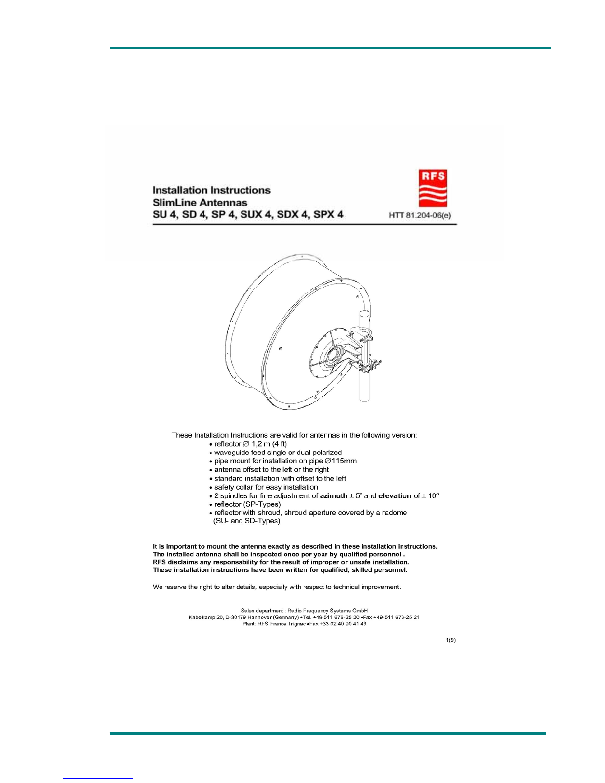
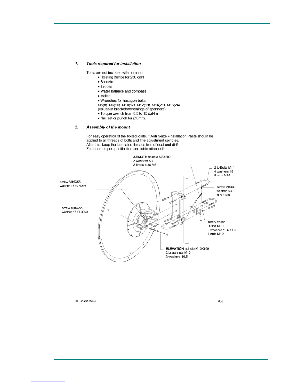
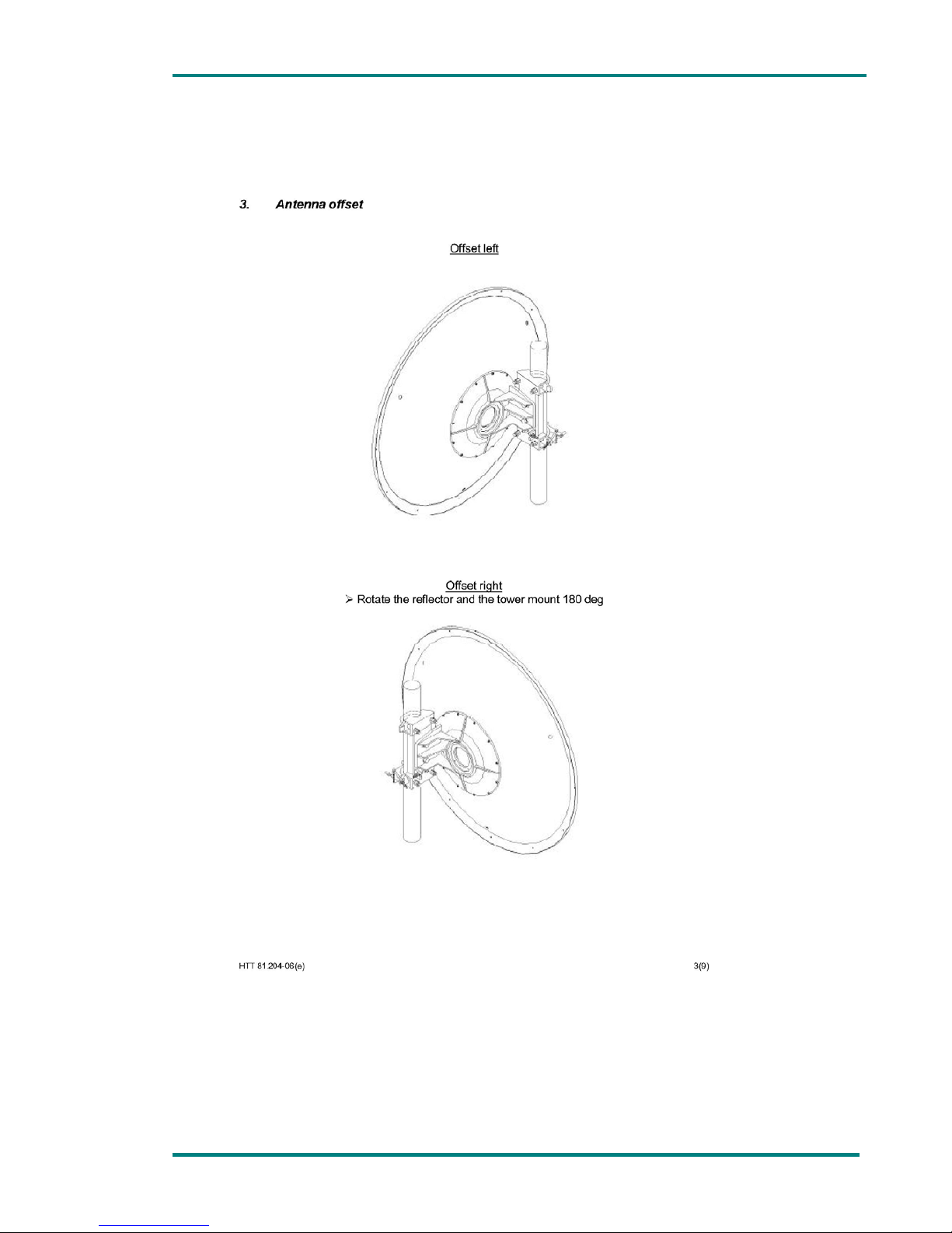
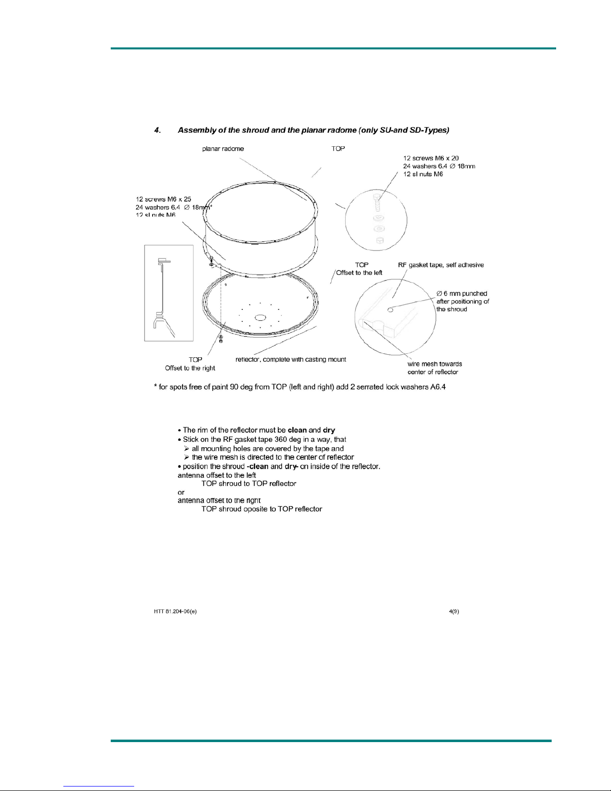
2. Parabolic antenna assembly for a point to point link ........................... 50
List of figures
Figure 1.1 Parabolic antenna and up-converter installation in a mast ....... 48
Figure 1.2 Parabolic antenna and up-converter installation for a point to
point link ......................................................................................... 49
Page 48
Chapter 3: Parabolic antenna installation
Page 48 VT-70 and UCM up-converter user’s manual
1. General installation instructions
Figure 1.1 Parabolic antenna and up-converter installation in a mast
Page 49
Chapter 3: Parabolic antenna installation
Page 49 VT-70 and UCM up-converter user’s manual
Figure 1.2 Parabolic antenna and up-converter installation for a point to
point link
Page 50
Chapter 3: Parabolic antenna installation
Page 50 VT-70 and UCM up-converter user’s manual
2. Parabolic antenna assembly for a point to
point link
Page 51
Chapter 3: Parabolic antenna installation
Page 51 VT-70 and UCM up-converter user’s manual
Page 52
Chapter 3: Parabolic antenna installation
Page 52 VT-70 and UCM up-converter user’s manual
Page 53
Chapter 3: Parabolic antenna installation
Page 53 VT-70 and UCM up-converter user’s manual
Page 54
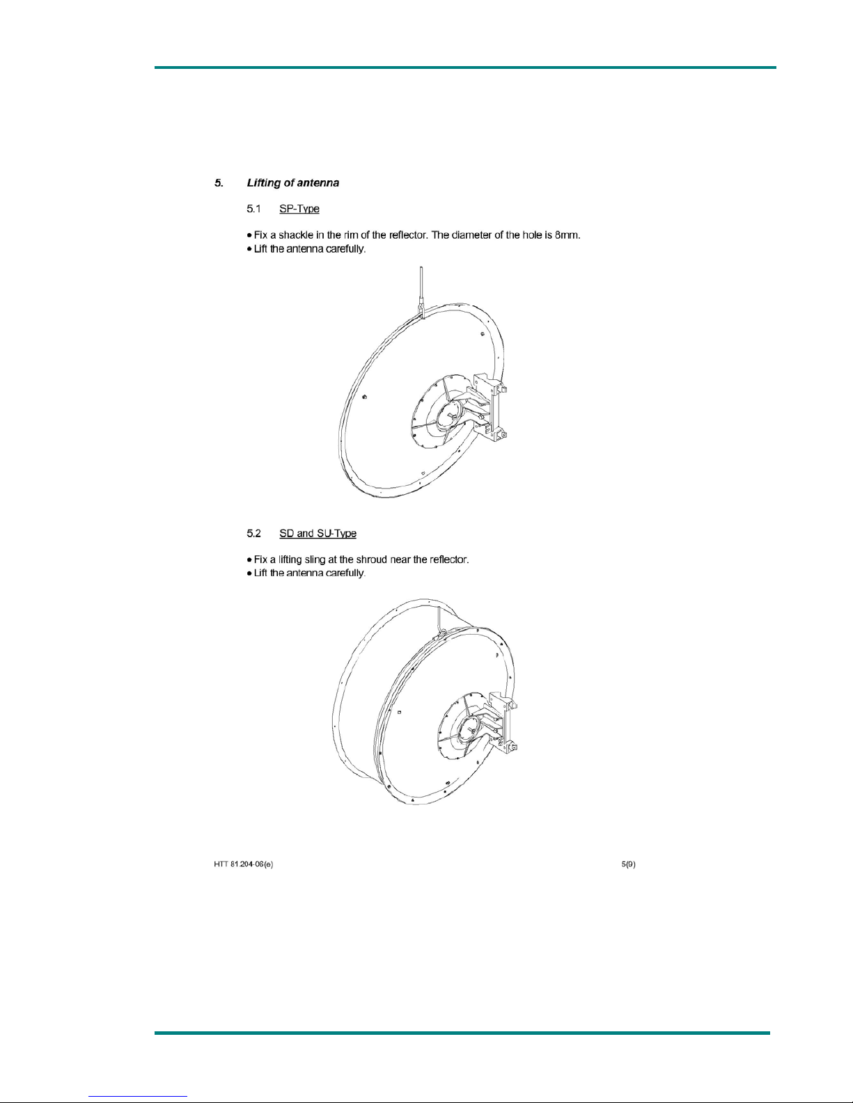
Chapter 3: Parabolic antenna installation
Page 54 VT-70 and UCM up-converter user’s manual
Page 55
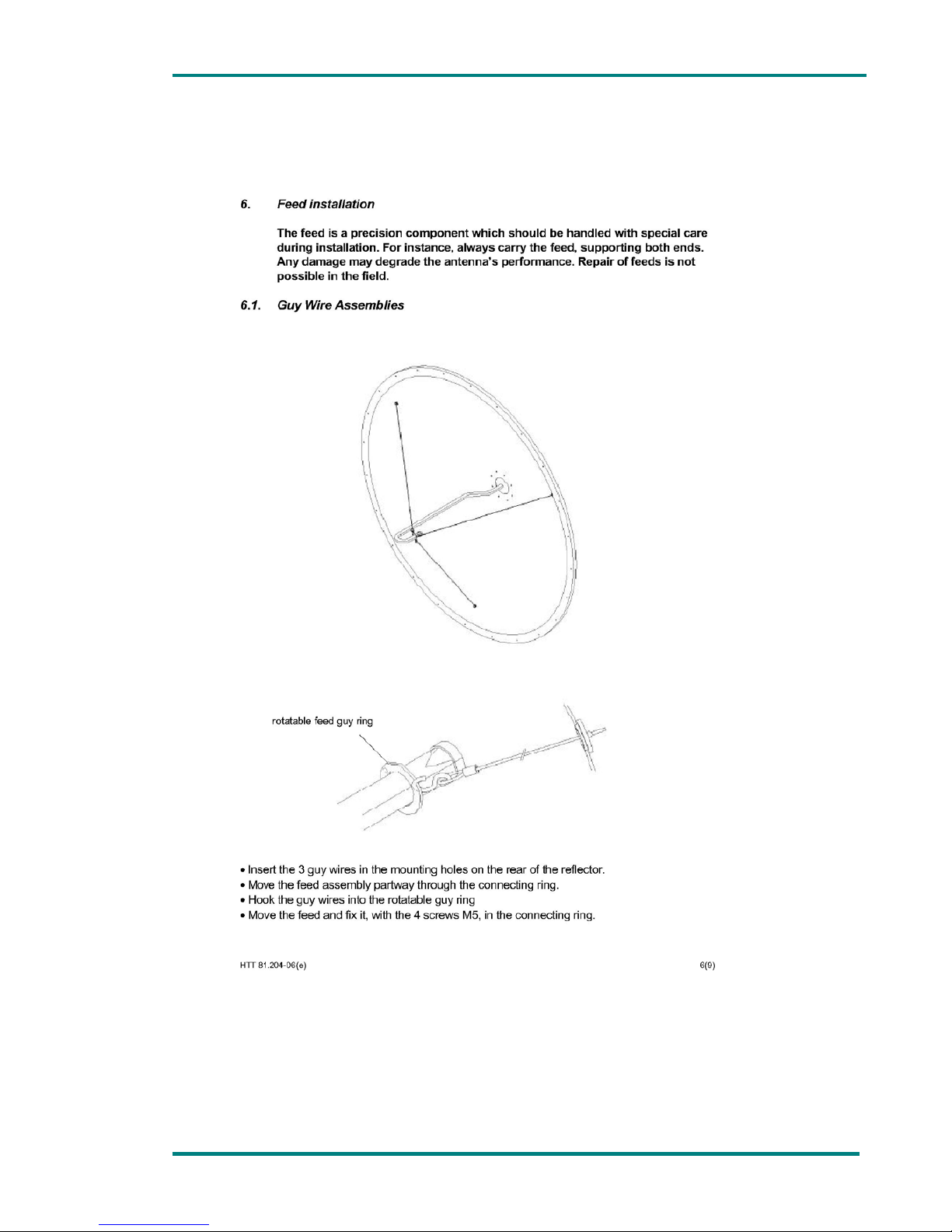
Chapter 3: Parabolic antenna installation
Page 55 VT-70 and UCM up-converter user’s manual
Page 56
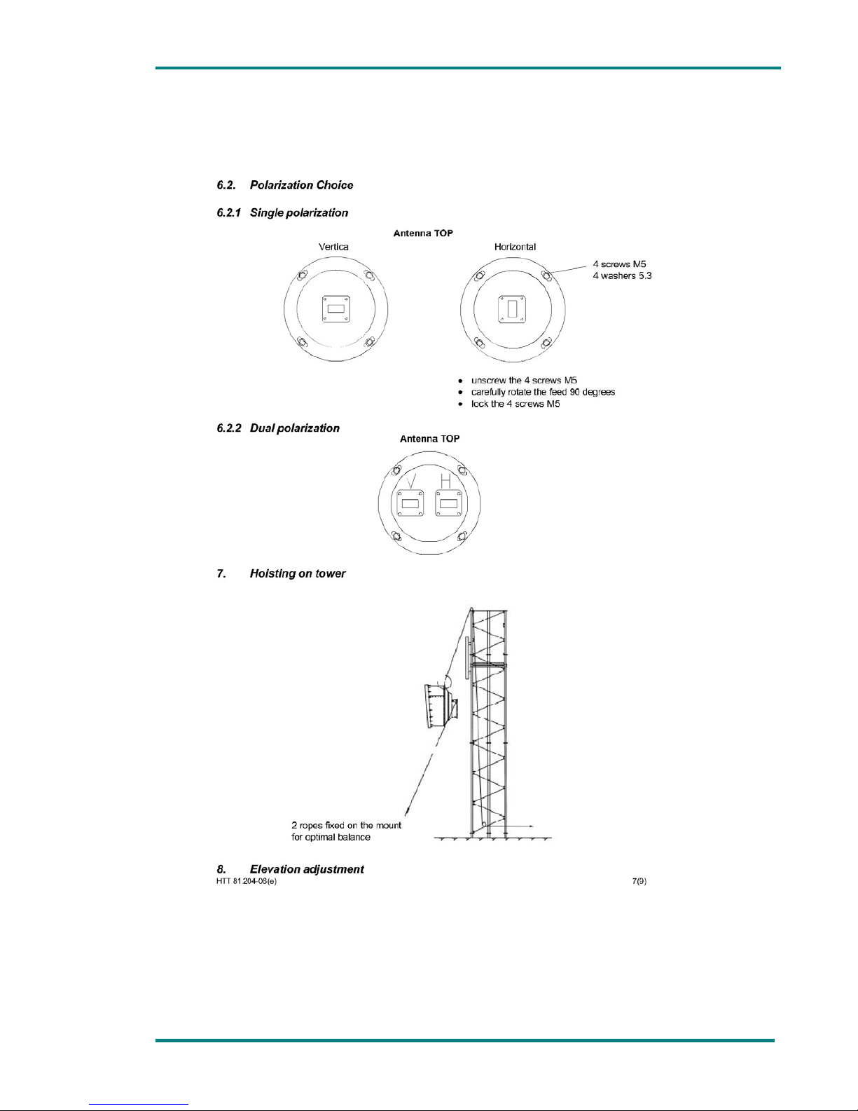
Chapter 3: Parabolic antenna installation
Page 56 VT-70 and UCM up-converter user’s manual
Page 57
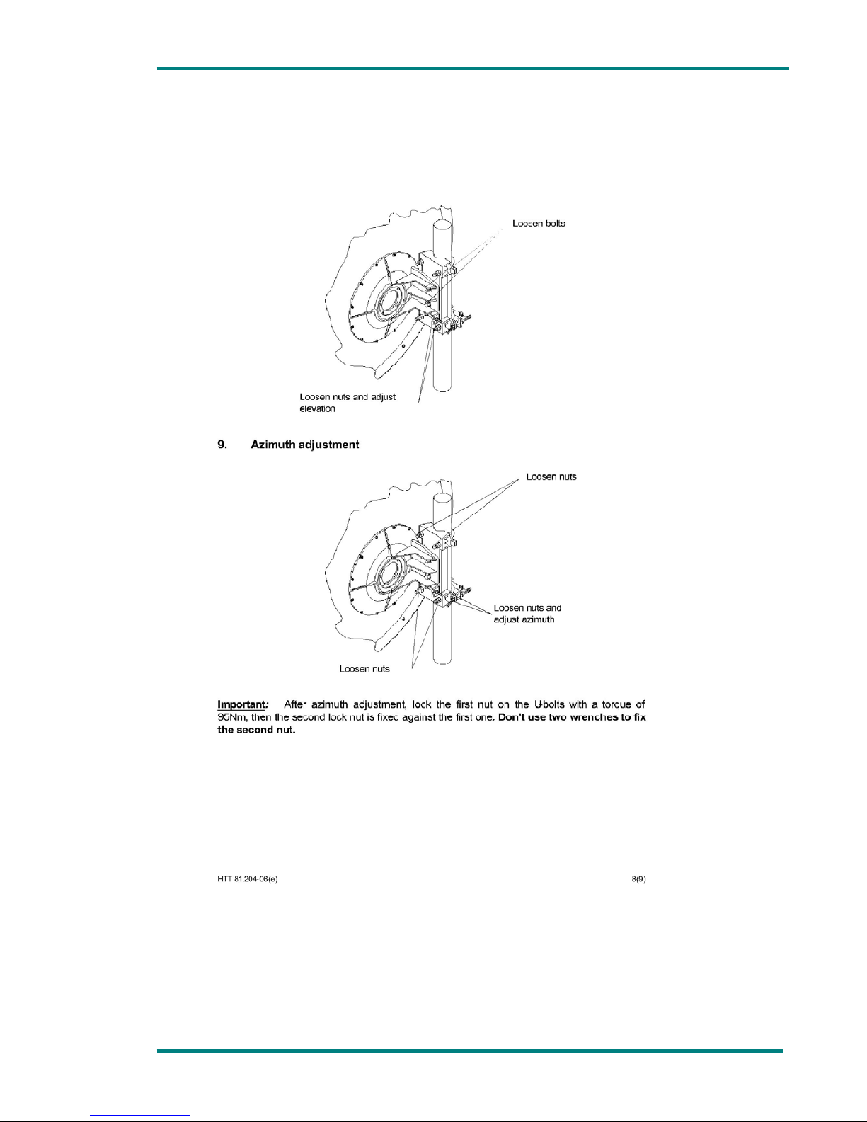
Chapter 3: Parabolic antenna installation
Page 57 VT-70 and UCM up-converter user’s manual
Page 58
Chapter 3: Parabolic antenna installation
Page 58 VT-70 and UCM up-converter user’s manual
Page 59
Chapter 3: Parabolic antenna installation
Page 59 VT-70 and UCM up-converter user’s manual
Page 60
Chapter 3: Parabolic antenna installation
Page 60 VT-70 and UCM up-converter user’s manual
Page 61
Chapter 3: Parabolic antenna installation
Page 61 VT-70 and UCM up-converter user’s manual
Page 62
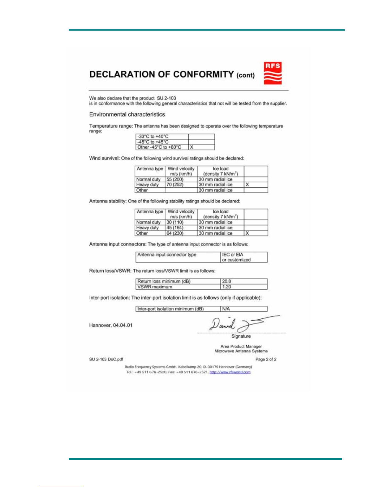
Chapter 3: Parabolic antenna installation
Page 62 VT-70 and UCM up-converter user’s manual
Page 63
Chapter 4
MD-70 External
Signal Meter
Page 64

Chapter 4:MD-70 External Signal Meter
VR-70 & DCM User’s Manual Page 64
Contents
1. MD 70 description ......................................................................... 65
2. Technical features ......................................................................... 66
List of tables
Table 2.1 Technical features ............................................................... 66
Page 65

Chapter 4:MD-70 External Signal Meter
VR-70 & DCM User’s Manual Page 65
1. MD 70 description
This new MD-70 meter is an instrument designed to measure several status
parameters in the UCM series up-converters and DCM series downconverters.
In the up-converters transmission frequency (MHz), transmission power
(Watt), power supply and temperature of them is measured.
In the down-converters the meter measures signal reception frequency
(MHz), received signal level (dBm), power supplied by the demodulator and
the temperature in the down-converter.
When the MD-70 meter is connected either to an up-converter or to a
down-converter, the display will show the start-up message (model and
version of the equipment) for a few seconds.
Afterwards, it will detect and display the model (DCM-1070 if it is a DownConverter UCM-7010 when it is an Up-Converter), software version and
serial number of the equipment the meter is connected to. Then the MD-70
meter displays the transmission frequency and output power if an upconverter has been connected or reception frequency and received signal
level, power supply and equipment temperature. This information is
displayed until the meter is disconnected or the equipment that is
connected to is switched off.
If the equipment is turned off having the MD-70 meter connected, when
turning the equipment on the display of the MD-70 will show the start-up
message (model and version of the meter) for a few seconds.
When in the up-converter or the down-converter the PLL is unlocked in
frequency, the frequency value blinks in the display of the MD-70.The same
happens when there is a power supply failure in the up-converter or in the
down converter, the value in the MD-70 meter blinks. Equally, if the
temperature in the up converter is higher than 60ºC or lower than -10ºC,
the temperature measurement displayed in the meter blinks.
These measurements provide the user with information to know the status
of the up or down converter at all times, and in case a failure occurs
(temperature or power supply) it will be very easy to identify. This meter is
also useful to install the equipments and to position the antenna. This
equipment is designed to use it outdoor in extreme conditions. It is
weatherproof and very robust.
This is an instrument that will help in the installation of the links and will
allow an excellent control of the maintenance parameters.
Page 66

Chapter 4:MD-70 External Signal Meter
VR-70 & DCM User’s Manual Page 66
2. Technical features
Table 2.1 Technical features
Item Specifications
Power supply +8 to 25 V. DC
Connector 4 pin 0B Lemo series
Cable length 1m (other cable lengths upon request
Page 67

VR-70 & DCM User’s Manual Page 67
NOTES:
Page 68

VR-70 & DCM User’s Manual Page 68
Final note
SVP Broadcast Microwave S.L. is constantly striving to improve all of its
products.
Therefore, we ask you to understand that modifications may occur in
designs, equipment and technology. Consequently, no responsibility can be
derived from the information, illustrations or descriptions contained in this
manual.
The texts, illustrations and instructions in the manual are based on the
existing situation when the manual is published.
Reprinting, reproduction and translation, in part or in whole, is
forbidden without written authorisation from SVP Broadcast
Microwave S.L.
SVP Broadcast Microwave reserves all rights regarding intellectual property
rights.
All rights reserved regarding modifications.
Page 69

SVP Broadcast Microwave reserves the right to make changes to this
manual and to the equipment without prior notice.
SVP
Broadcast
Microwave
C/Uralde, 2
48215 Iurreta
Vizcaya – España
Tel: (+34) 94620 3722
www.svpbm.com
 Loading...