

Page 1

HENM-70
H.264 – 4:2:2
Encoder & DVB-S2/S Modulator
USER MANUAL V5.6
Page 2

I
HENM-70 Encoder & DVB-S2/S Modulator
USER’S MANUAL V5.6
Contents
Chapter 1: Introduction
This first chapter provides a general description of the High Definition
HENM-70 encoder and DVB-S2/S modulator.
Chapter 2: Technical features
This second part offers the encoder’s and modulator’s physical and
environmental characteristics.
Chapter 3: HENM-70 operation and Menus
This third part provides the user all the necessary information to control and
operate the equipment properly. It is detailed the function of each button on
the keyboard. It is also explained how the information is shown on the
display, HENM-70 menus, etc.
Chapter 4: GPS Application
In this chapter, the use of the GPS incorporated system and some of its
applications are shown.
Chapter 5: Web Server
This chapter provides a detailed description of the Web Server tool. This
feature allows the control of the HENM-70 encoder and DVB-S2/S modulator
through a website.
Chapter 6: Equipment Installation
This chapter indicates the available connections of the HENM-70, their
characteristics and the installation of the equipment.
Page 3

II
HENM-70 Encoder & DVB-S2/S Modulator
USER’S MANUAL V5.6
Dear customer,
We would like to thank you for selecting this equipment and welcome you to
the SVP’s growing family of products.
We are sure that the addition of this equipment will cause you a complete
satisfaction in your existing installation.
Please read these instructions carefully, and keep them in hand in case you
have to refer to them.
Page 4
III
HENM-70 Encoder & DVB-S2/S Modulator
USER’S MANUAL V5.6
About this manual
This user’s guide provides indications and explanations about how to set up
easily the HENM-70 encoder & modulator for the most common use cases.
This document is intended to help first time users:
- To find their way around the GUI.
- To understand the different possibilities of the HENM-70.
- To configure the HENM-70 for their specific configurations.
Symbols
The symbols that appear in this manual are:
An information message which indicates explanations for the
proper operation of the equipment.
This symbol advises users that if they do not take, avoid or
make specific actions, several damages could appear in the
device.
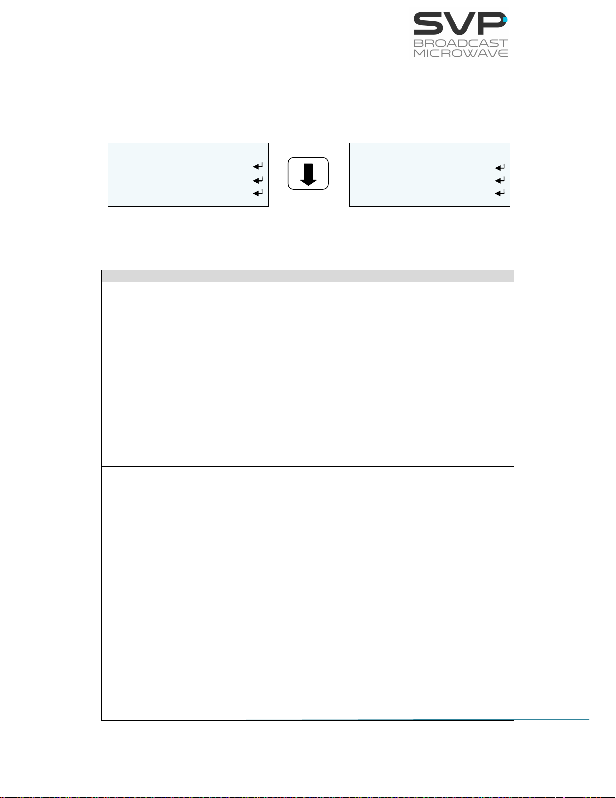
In the places where this symbol appears it means that by
pressing the Down button of the equipment the user can
access to the next screen.
This symbol means that pressing the OK button in the options
where this symbol appear, the user can access to the submenu
related to that option or can change the value of the
parameter.
<> These symbols mean that the parameter can be modified in the
same screen with the right and left keys.
Page 5

IV
HENM-70 Encoder & DVB-S2/S Modulator
USER’S MANUAL V5.6
Important Notes
1. The HENM-70 encoder and DVB-S2/S modulator is completely
compatible with the DVB-S2 Standard, included in the European
Standard ETSI EN302307 (DVB-S2) and ETSI EN300421 (DVB-S).
2. The HENM-70 encoder and DVB-S2/S modulator applies a MPEG-4
compression to either HDMI, composite video or SDI input signals. An
MPEG-1 layer 2 compression is applied to the corresponding 2 analogue
audio channels, the 2 stereo SDI embedded, the HDMI embedded and
the AES digital audio signals. The resulting multiplexed signal is
transmitted using COFDM modulation system.
3. This device has the ASI and IP output available when the input is ASI.
Besides, it has also the ASI output available when the input is IP.
4. The HENM-70 encoder and DVB-S2/S modulator is available for L band.
5. In 1080p Video Format, it can only be performed the Standard Delay,
not the Low Delay, Super Low Delay or Ultra Low Delay.
6. In case it is selected SDI input with 1080p format, the delay will be
automatically Standard.
7. Equipment maximum output power is from -20 to + 5 dBm.
8. Special care should be taken with SDI cables, quality and length, these
are very important, especially when HD-SDI or 3G-SDI signals are
transmitted.
9. If any audio or data channel are not to be used in a transmission, they
should be disabled, in order to assign that bitrate to the video and
achieve a higher quality transmitted video signal.
10.Only authorized personnel should open the product and any repair or
warranty will be invalidated if the seals are broken.
Page 6
V
HENM-70 Encoder & DVB-S2/S Modulator
USER’S MANUAL V5.6
First Aid in Case of Electric Shock
DO NOT TOUCH THE VICTIM WITH YOUR BARE HANDS until the circuit is
broken. SWITCH OFF. If this is not possible, PROTECT YOURSELF with DRY
insulating material and pull the victim clear of the conductor.
If breathing has stopped, indicated by unconsciousness, lack of respiratory
movements and a ‘blue’ look to cheeks, lips, ears and nails, START
RESUSCITATION AT ONCE.
EMERGENCY RESUSCITATION – THE EXPIRED AIR METHOD
(Approved by the Royal Life Saving Society)
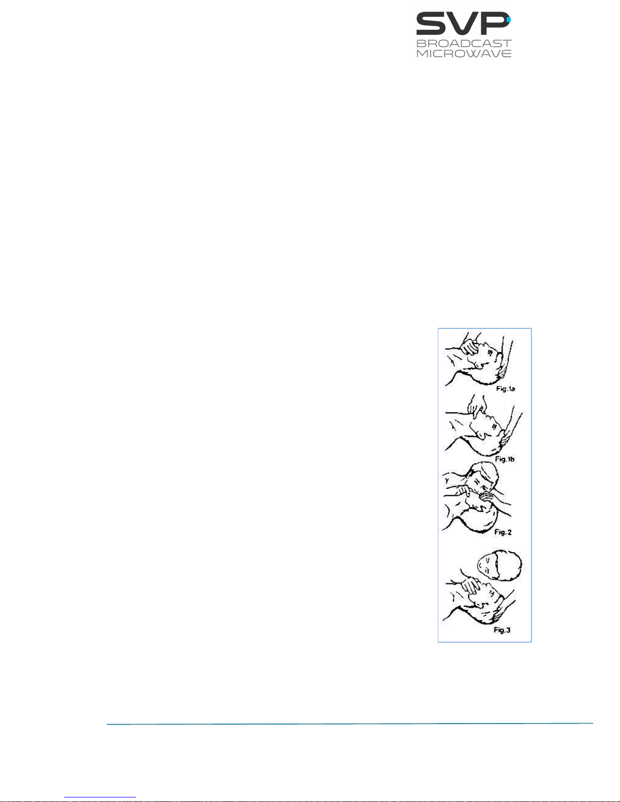
1. If possible, lie the victim on his back with his head slightly higher
than his feet. Clear the mouth and throat of any obvious obstruction.
2. Kneel on one side of the victim, level with his head. LIFT THE JAW
AND TILT THE HEAD BACK AS FAR AS POSSIBLE (Figs. 1a and 1b)
3. One of the following may happen:
a) Breathing may begin and consciousness
returns.
b) Breathing may begin but consciousness NOT
return. Turn the victim on his side and ensure
that the airway is kept clear.
c) Breathing may return but be NOISY which
means that the airway is not fully clear. Try to
clear the airway.
4. IF THERE NO SIGN OF BREATHING:
a) Check that the head is still tilted back.
b) Take a deep breath.
c) Pinch the victim’s nose and blow firmly into his
mouth (Fig. 2). As you do, the chest will RISE.
d) Turn your head away and take another breath,
watching for the chest to FALL (Fig. 3).
5. Start with four quick breaths and then continue with
one breath every five seconds (i.e. 12 times a
minute). This should be continued until the victim
revives or a doctor certifies death.
6. As consciousness returns the victim will start to
breathe on his own, and a ‘pink’ color replaces the
‘blue’ look: this is the time to stop resuscitation.
Continue to hold his chin up and so keep the airway clear.
7. In the case of injuries to the mouth, it may be necessary to use
mouth-to-nose resuscitation. Seal the victim’s mouth with your cheek
and blow firmly into his nose, proceeding as above.
Page 7

VI
HENM-70 Encoder & DVB-S2/S Modulator
USER’S MANUAL V5.6
8. In the case of severe facial injuries it may be necessary to do a
manual method of artificial respiration (Silvester-Brosch or Holger
Nielsen). Briefly, these methods apply compression to ribcage with
the victim lying on his back (S-B) or face down (H.N.) with associated
movement of his arms up and out. The cycle of movement should
take about five seconds, i.e. the normal breathing phase.
9. Whatever the method, it is ESSENTIAL to commence resuscitation
WITHOUT DELAY and to send for medical assistance immediately.
TREATMENT FOR BURNS
If the victim is also suffering from burns, then, without hindrance to
resuscitation, observe the following:
a) DO NOT ATTEMP TO REMOVE CLOTHING ADHERING TO THE BURN.
b) If possible alleviate the pain from the burnt part by immersing in
cold water.
c) If help as available or as soon as resuscitation is no longer required
the wound should be covered with a DRY clean dressing.
d) Oil or grease in any form should not be applied.
e) If severely burnt, get the victim to hospital immediately.
Page 8

1
HENM-70 Encoder & DVB-S2/S Modulator
USER’S MANUAL V5.6
Main Index
Chapter 1: Introduction ....................................................................... 4
Chapter 2: Technical Features .............................................................. 7
Chapter 3: HENM-70 Operation and Menus ........................................... 10
3.1 Display .................................................................................. 10
3.1.1 Main Screen for the DVB-S2 ............................................... 13
3.1.2 Main Screen for the DVB-S ................................................. 15
3.2 Configuration Examples ........................................................... 17
3.3 LEDs ..................................................................................... 20
3.4 Front panel ............................................................................ 21
3.4.1 ON/OFF Button ................................................................. 21
3.4.2 OK Button ........................................................................ 22
3.4.3 Cross Button .................................................................... 22
3.4.4 Left and Right Button ........................................................ 23
3.4.5 Up and Down Button ......................................................... 23
3.5 Menus ................................................................................... 24
3.5.1 Menu Navigation ............................................................... 29
3.5.2 Menu Structure ................................................................. 30
3.5.2.1 Encoder Menu ............................................................. 31
3.5.2.1.1 SDI Input .............................................................. 33
3.5.2.1.2 HDMI Input ........................................................... 35
3.5.2.1.3 CVBS Input ........................................................... 37
3.5.2.1.4 ASI Input .............................................................. 39
3.5.2.1.5 IP Input ................................................................ 40
3.5.2.1.6 Generator Input ..................................................... 44
3.5.2.1.7 Audio1 Embedded .................................................. 45
3.5.2.1.8 Audio1 Analogue .................................................... 46
3.5.2.1.9 Audio1 AES-EBU .................................................... 47
3.5.2.1.10 Audio1 Tone.Gen ................................................... 48
3.5.2.1.11 Audio2 Embedded .................................................. 49
3.5.2.1.12 Audio2 Analogue .................................................... 50
3.5.2.1.13 Audio2 AES-EBU .................................................... 51
3.5.2.1.14 Audio2 Tone.Gen ................................................... 52
3.5.2.1.15 Data ..................................................................... 53
3.5.2.1.16 Encoder Output ..................................................... 56
3.5.2.1.17 TS Parameters ....................................................... 57
3.5.2.2 CA-BISS Menu ............................................................ 59
3.5.2.3 Modulator Menu .......................................................... 60
3.5.2.3.1 DVB-S2 ................................................................ 61
3.5.2.3.2 Symbol Rate calculation .......................................... 64
3.5.2.3.3 DVB-S .................................................................. 65
3.5.2.4 IP Out ........................................................................ 68
3.5.2.5 Unit Menu ................................................................... 70
Page 9

2
HENM-70 Encoder & DVB-S2/S Modulator
USER’S MANUAL V5.6
3.5.2.5.1 Alarms .................................................................. 70
3.5.2.5.2 Monitor ................................................................. 71
3.5.2.5.3 Webserver & SNMP ................................................ 72
3.5.2.5.4 Miscellaneous ........................................................ 74
3.5.2.5.5 Firmware .............................................................. 76
3.5.2.5.6 BUC S/S2 Unit ....................................................... 80
Chapter 4: GPS Application ................................................................. 81
4.1 Introduction ........................................................................... 81
4.2 Main Screen ........................................................................... 81
4.3 GPS transmitter screen ........................................................... 82
4.4 GPS IRD-70 decoder screen ..................................................... 83
4.5 Application example ................................................................ 85
Chapter 5: Web Server ....................................................................... 87
5.1 Introduction ........................................................................... 87
5.2 Web Page Overview ................................................................ 89
5.2.1 ENCODER ......................................................................... 90
5.2.1.1 Video ......................................................................... 90
5.2.1.2 Audio ......................................................................... 91
5.2.1.3 Data .......................................................................... 92
5.2.1.3.1 GPS...................................................................... 93
5.2.1.4 TS Parameters ............................................................ 94
5.2.1.5 Output ....................................................................... 95
5.2.2 MOD_RF .......................................................................... 96
5.2.2.1 DVB-S2 ...................................................................... 97
5.2.2.2 DVB-S ........................................................................ 99
5.2.3 TSoIP ............................................................................ 101
5.2.3.1 IP Output ................................................................. 102
5.2.3.2 IP Input ................................................................... 103
5.2.4 CA-BISS ........................................................................ 106
5.2.5 UNIT ............................................................................. 107
5.2.5.1 LEDs Status (reading parameters) ............................... 108
5.2.5.2 Alarms (reading parameter) ........................................ 108
5.2.5.3 Configuration ............................................................ 109
5.2.5.4 Monitor .................................................................... 110
5.3 Web Page Setup Notes .......................................................... 111
5.4 SNMP .................................................................................. 111
5.4.1 SNMP commands ............................................................ 112
Chapter 6: Equipment Installation ..................................................... 113
6.1 Introduction ......................................................................... 113
6.2 Connections ......................................................................... 113
6.2.1 Power supply .................................................................. 115
AC Power supply ..................................................................... 115
DC Power supply ..................................................................... 116
6.2.2 Intermediate frequency ................................................... 118
DVB-S2 output ........................................................................ 118
Intermediate frequency output IF .............................................. 118
Page 10

3
HENM-70 Encoder & DVB-S2/S Modulator
USER’S MANUAL V5.6
6.2.3 ASI ............................................................................... 119
ASI input ................................................................................ 119
ASI output .............................................................................. 119
6.2.4 CVBS/ SDI/ HDMI ........................................................... 120
6.2.5 Transport Stream over IP ................................................. 121
Transport Stream over IP Input and Output ................................ 121
6.2.6 Audio inputs ................................................................... 122
6.2.7 Data/GPS input ............................................................... 124
6.2.8 USB connection .............................................................. 125
6.2.9 Ethernet ........................................................................ 125
Page 11

4
HENM-70 Encoder & DVB-S2/S Modulator
USER’S MANUAL V5.6
Chapter 1: Introduction
The HENM-70 is the new equipment developed by SVP Broadcast
Microwave, which includes a H.264 – 4:2:2 encoder and a DVB-S2/S
modulator in the same equipment.
Its feature H.264 encodes for 3G, high definition (HD) and standard
definition (SD) signals, being able to detect automatically the video input
format. Based on NTT-NEL encoding technology, the new HENM-70 offers
the highest video quality with the minimum latency, 33 ms.
Leveraging the latest modulation technology, the HENM-70 provides a high
signal quality solution. It has been designed to address the requirements of
the ETSI DVB-S2 forward-link satellite standard (EN302307).
For added security, the transmitted signal can be encrypted using BISS
encryption.
ASI Transport Stream over IP and 2D FEC encoding as defined in SMPTE
2022 allows sending the signals over IP networks.
In its default configuration, the encoder & modulator is able to transmit one
MPEG transport stream in DVB-S2 or DVB-S mode.
At the output of the modulator, the signal is available in IF from 950 to
2150 MHz. A switchable 10 MHz reference signal is multiplexed on the Lband interface, providing a compact and cost effective solution for the upconverters which need external frequency reference.
The HENM-70 has been designed to be used in broadcast and professional
applications.
Page 12

5
HENM-70 Encoder & DVB-S2/S Modulator
USER’S MANUAL V5.6
Features
Input video signals, composite video, 3G –SDI, HD-SDI, SD-SDI or HDMI
are MPEG-4 encoded, together with 4 analogue audios, 2 stereo AES/EBU
channels or 4 digital audios embedded on the SDI signal. The video
formats can be 1080p (only in Standard Delay mode), 1080i, 720p, 576i or
480i. This transmitter also has a test pattern and test tone generator
available.
This device has a data channel available that allows transmitting user data
or GPS data as well as a Transport Stream ASI input so it can be used as a
repeater.
The encoder uses a H.264/MPEG-4 Part 10 video compression that provides
output bitrates from 1 Mbps to 216 Mbps and a MPEG-1 Layer II audio
compression which supplies different audio bit rates (128, 192, 256 or 384
Kbps).
Encoded signals can be encrypted using BISS-1 or BISS-E scrambling
system. Encrypted signal will only be received by the receivers that have a
valid descrambling key.
The transmitter system operation is very easy. It has a display and a
keyboard which make possible the configuration and monitorization of every
parameter of the equipment.
The equipment is fed with AC power supply from 100 to 240 V or with a DC
power supply from 8 to 36V.
Its excellent design, mechanical and electronic assembly make the HENM70 a robust and reliable solution.
DVB-S2 features
In case the HENM-70 encoder & modulator is needed to be used as a
satellite transmitter, it features an IF stage in the L band with an output
power level from -50 to +5 dBm and a L band output that provides a 10
MHz reference oscillator.
The HENM-70 uses single carrier or one modulation from the next available:
QPSK, 8PSK, 16APSK or 32APSK where the most robust is the QPSK one
and the one with the bigger bit rate is the 32APSK.
In addition, the European ETSI EN 302307 standard defines the following
LDPC coding rates: 1/4, 1/3, 2/5, 1/2, 3/5, 2/3, 3/4, 4/5, 5/6, 8/9, 9/10.
In the modulation step it is also included a roll off factor (0,20, 0,25, 0,35)
which is used to reduce the intersymbol interference where the value that
most reduces the interference but with less bandwidth is 0,20.
Page 13

6
HENM-70 Encoder & DVB-S2/S Modulator
USER’S MANUAL V5.6
To sum up, with all of these characteristics, the maximum bit rate achieved
is 31 Msym/s.
DVB-S features
The HENM-70 features an IF stage in the L band with an output power level
from -50 to +5 dBm and an L band output that provides a 10 MHz reference
oscillator.
The HENM-70 uses QPSK modulation. In addition, the European ETSI EN
300421 standard defines the following Reed Solomon coding rates: 1/2,
2/3, 3/4, 5/6, 7/8.
Page 14

7
HENM-70 Encoder & DVB-S2/S Modulator
USER’S MANUAL V5.6
Chapter 2: Technical Features
IF Stage (L Band) DVB-S2 and DVB-S
Frequency Range: 950 to 2.150 MHz (L band)
Output Power Level: -50 to +5 dBm
10 MHz Ref. Oscillator: 0 dBm
Frequency Tolerance: ± 1.0 ppm
Frequency Stability: ± 0.30 ppm
Operating Temperature Range:-40 to +85ºC
Phase Noise: 10Hz_____-100 dBc/Hz
100Hz____-130 dBc/Hz
1KHz_____-147 dBc/Hz
10KHz____-156 dBc/Hz
100KHz___-160 dBc/Hz
1MHz_____-160 dBc/Hz
IF Stage (70 MHz) DVB-S2 and DVB-S
Frequency: 70 MHz
Output Power Level: -10 dBm (DVB-S/S2)
-14 dBm (DVB-T/T2)
Video:
Inputs: 3G-SDI SMPTE-425M-A(299M)
HD-SDI SMPTE-292M(299M)
SD-SDI SMPTE-259M(272M)
HDMI (1.4a)
Composite video (PAL/NTSC)
Formats: 1080p (1920x1080) – 23.98/24/25/
29.97/30/50/59.94/60 Hz
1080i (1920x1080) – 50/59.94/60 Hz
720p (1280x720) – 23.98/24/25/29.97/
30/50/59.94/60 Hz
576i (720x576) – 50 Hz
480i (720x480) – 59.94 Hz
Audio:
Input: SDI embedded / HDMI embedded
AES Digital / Analogue
Analogue: 2 Stereo / 4 Mono
Line, Micro Dynamic and Micro with
Phantom
Page 15

8
HENM-70 Encoder & DVB-S2/S Modulator
USER’S MANUAL V5.6
SDI embedded: 1 Group (4 audio channels)
AES/EBU: 2 Stereo channels
Data Channels
Data channel: User data or GPS
Data rate: 1.200 to 57.600 bps
ASI and IP
Input and Output: ASI Transport Stream (EN50083-9)
Transport Stream over IP
(SMPTE2022/CoP3) - FEC
188/204 byte-packets
Max. TS packets / IP packet: 7
Encoder
Video compression: H.264/MPEG-4 Part 10
Profile: High 422, High, Main
Level: 3.0/3.1/3.2/4.0/4.1
Latency: Ultra Low delay: 33 ms
Audio compression: MPEG-1 Layer II
Audio bitrate: 128, 192, 256 or 384 Kbps
Output bitrate: 1 Mbps – 100 Mbps
Modulation
DVB-S2: QPSK, 8PSK, 16 APSK, 32 APSK
LDPC FEC: 1/4, 1/3, 2/5, 1/2, 3/5, 2/3, 3/4,
4/5, 5/6, 8/9, 9/10
Max. Symbol Rate: 31 Msymb/s
Max. Bandwidth @ Rolloff: 0.35= 41.85 MHz
Max. Bitrate: 89.732 Mbps
DVB-S: QPSK
Reed Solomon FEC: 1/2, 2/3, 3/4, 5/6, 7/8
Baud Rate: 31 Msymb/s
Page 16

9
HENM-70 Encoder & DVB-S2/S Modulator
USER’S MANUAL V5.6
Encryption
BISS: BISS-1 and BISS-E
AES: AES-128 and AES-256 (Optional)
Control & Monitorization
Control Interfaces: Front panel & display
Web Server interface
SNMP
RTC-01 via cable
Monitoring: Encoding parameters
Modulation parameters
Alarms and warnings
Test Signals
Video: Bars with moving icon
Audio: 4 Audio tones
Power Supply
AC input: 100 to 240V
DC input: 8 to 36 V
Consumption: 18W @ 12V
Mechanical
Size: ½ RU, 210x44x240 mm (WxHxD)
Weight: 1,8 Kg
Environmental
Temperature range: -10 to 45 ºC
Height: 4.500 m
Humidity: 95%
Page 17
10
HENM-70 Encoder & DVB-S2/S Modulator
USER’S MANUAL V5.6
Chapter 3: HENM-70 Operation and Menus
This third chapter provides the user all the necessary information to control,
configure and operate the equipment properly.
3.1 Display
To switch the equipment on and off, press the ON/OFF button. When the
equipment is turned on, the display will show the start-up message (model
and version of the equipment) for two seconds.
When a video, audio or data input has been selected, a character connected
to this input is displayed in the main screen.
Next, the main screen of the HENM-70 encoder & modulator is shown.
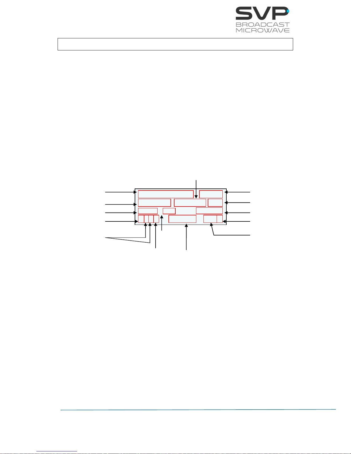
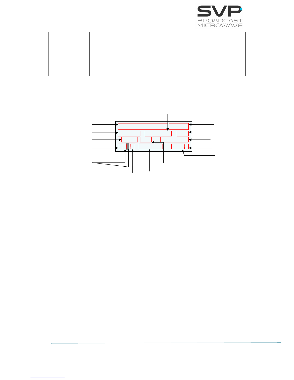
Figure 3.1 HENM-70 front panel/ Main screen explanation
F: 1350,000MHz DVBS2
P:+0dBm SR12.400 B15
QPSK 3/4 18.000
SGGG 576/50i 420S
Frequency
Output Power
Modulation Scheme
Video Input Selection
Audio Input Selection
Symbol Rate
Data Input Selection
FEC
Input Video Signal Format
Transmission Standard
Bandwidth
Bitrate
Latency
Encoder Video Profile
Page 18

11
HENM-70 Encoder & DVB-S2/S Modulator
USER’S MANUAL V5.6
The parameters shown in the principal screen are:
Frequency (MHz).
Transmission Standard (DVB-S2/S).
Output power (dBm).
Symbol Rate (Msymb/s).
Bandwidth (MHz) (monitored).
Modulation Scheme (QPSK, 8PSK, 16APSK, 32APSK).
FEC (3/5, 2/3, 3/4, 5/6, 8/9, 9/10).
Transmitted bitrate (Mbps).
Video input selection
- Possibilities: CVBS, HDMI, SDI, DVB-ASI Transport Stream, IP or
Generator.
- Behaviour of the corresponding character: If the character is
static then it means presence of that signal. If the character is
blinking then it means absence of that signal.
Audios status indication: If audio 1 or 2 is not darkened then it is
enabled. On the other hand, if audio 1 or 2 is darkened then it is
disabled.
Data status indication: If this field is not darkened then it means that
data is enabled. On the other hand, if this value is darkened it means
that data is disabled. Moreover, in case this field is static, its meaning is
presence of the data whereas if this field is blinking, it means absence of
the data.
Input video signal format.
Encoder Video Profile (4.2.0 or 4.2.2)
Latency (Standard delay, Low delay, Super Low Delay or Ultra Low
delay)
- Standard Delay (Lipsync < 10 ms)
- Low delay (Lipsync < 10 ms) 3 frames
- Super Low Delay (Lipsync < 10 ms) 2 frames
- Ultra Low Delay (Lipsync = 20 ms) 1 frame
Page 19

12
HENM-70 Encoder & DVB-S2/S Modulator
USER’S MANUAL V5.6
Next, the linkages between the input and the character displayed in the
principal screen are shown:
Video
Composite
Video
C
HDMI
H
SDI S
ASI A IP I
Test Pattern
G
Audio
Embedded
E
AES/EBU
U
Analogue
A
Test Tone
G
Data
RS232
D
GPS
G
Table 3.1 Linkages between the input and the character displayed
Next, the main screen for each output type (DVB-S2 and DVB-S) is shown:
Page 20

13
HENM-70 Encoder & DVB-S2/S Modulator
USER’S MANUAL V5.6
3.1.1 Main Screen for the DVB-S2
In the table below, the function of each parameter is explained. These
values are numbered in the order they appear in the main screen.
Parameter nº
Function
1
Transmission frequency (MHz)
2
Transmission standard (DVB-S2)
3
Output power (dBm)
4
SR (Msymb)
5
Bandwidth
6
Modulation (QPSK, 8PSK, 16APSK, 32APSK)
7
LDPC FEC (1/4, 1/3, 2/5, 1/2, 3/5, 2/3, 3/4, 4/5, 5/6, 8/9, 9/10)
9
Transmitted bitrate (Mbps)
10
Character 1:
Video input selection (CVBS, HDMI, SDI, DVB-ASI Transport
Stream or Generator) and (static -> presence / blinking ->
absence)
Characters 2 (Audio 1) and 3 (Audio 2):
Audio inputs selection (Analog, Embedded or AES/EBU) and
(Audio 1 and 2 not darkened -> enabled / darkened ->
disabled)
Character 4:
Data input selection (None, GPS, RS232, RS485 or UDP) and
(not darkened -> enabled / darkened -> disabled) and (static
-> presence / blinking -> absence)
11
Video Format (1080p, 1080i, 720p, 576i, 480i)
Page 21
14
HENM-70 Encoder & DVB-S2/S Modulator
USER’S MANUAL V5.6
12
Video options:
Profile (MPEG-4 4:2:0 or MPEG-4 4:2:2)
Delay (Standard (S), Low delay (L), Super Low delay (SL) or
Ultra Low delay (UL))
Table 3.2 Main screen for DVB-S2 standard
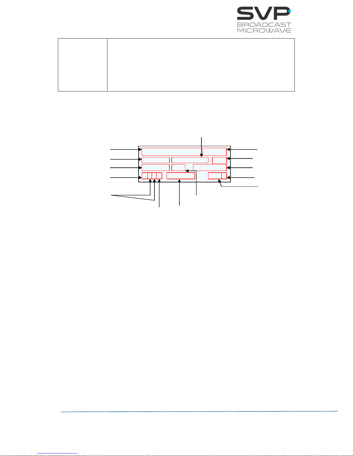
Figure 3.2 Main screen for DVB-S2 standard
F: 14000,000MHz DVBS2
P: +0.0 SR12.4000 B16
32APSK 8/9 53.300Mb
GEAD 576/50i 420S
Frequency
Output Power
Modulation Scheme
Video Input Selection
Audio Inputs Selection
Data Input Selection
Input Video Signal Format
Transmission Standard
Bandwidth
Bitrate
Latency
Encoder Video Profile
FEC
Symbol Rate
Page 22

15
HENM-70 Encoder & DVB-S2/S Modulator
USER’S MANUAL V5.6
3.1.2 Main Screen for the DVB-S
In the table below, the function of each parameter is explained. These
values are numbered in the order they appear in the main screen.
Parameter nº
Function
1
Transmission frequency (MHz)
2
Transmission standard (DVB-S)
3
Output power (dBm)
4
SR (Msymb)
5
Bandwidth
6
Modulation (QPSK)
7
LDPC FEC (1/2, 2/3, 3/4, 5/6, 7/8)
9
Transmitted bitrate (Mbps)
10
Character 1:
Video input selection (CVBS, HDMI, SDI, DVB-ASI Transport
Stream or Generator) and (static -> presence / blinking ->
absence)
Characters 2 (Audio 1) and 3 (Audio 2):
Audio inputs selection (Analog, Embedded or AES/EBU) and
(Audio 1 and 2 not darkened -> enabled / darkened ->
disabled)
Character 4:
Data input selection (None, GPS, RS232, RS485 or UDP) and
(not darkened -> enabled / darkened -> disabled) and (static
-> presence / blinking -> absence)
11
Video Format (1080p, 1080i, 720p, 576i, 480i)
Page 23
16
HENM-70 Encoder & DVB-S2/S Modulator
USER’S MANUAL V5.6
12
Video options:
Profile (MPEG-4 4:2:0 or MPEG-4 4:2:2)
Delay (standard (S), low delay (L), super low delay (SL) or
ultra low delay (UL))
Table 3.3 Main screen for DVB-S standard
Figure 3.3 Main screen for DVB-S standard
F: 1360,500MHz DVBS
P: +3.0 SR08.000 B10
QPSK 7/8 12.901Mb
SEx D 1080/50i 420L
Frequency
Output Power
Modulation Scheme
Video Input Selection
Audio Inputs Selection
Data Input Selection
Input Video Signal Format
Transmission Standard
Bandwidth
Bitrate
Latency
Encoder Video Profile
FEC
Symbol Rate
Page 24
17
HENM-70 Encoder & DVB-S2/S Modulator
USER’S MANUAL V5.6
3.2 Configuration Examples
Next, some setup examples and the image that appears in the monitor
screen are shown.
Example 1 (DVB-S2)
Setup:
Frequency: 1500,000 MHz
Transmission Standard: DVB-S2
Output power: +2 dBm
Symbol rate: 8 Msymb/s
Bandwidth: 10 MHz
Modulation Scheme: 16APSK
FEC: 4/5
Transmitted BitRate: 30.000Mbps
Video input selection: HDMI
Audio input selection: Audio1 Analogue (enabled), Audio2 AES/EBU
(disabled)
Data input selection: GPS
Input video signal format: 1080p
Encoder Video Profile: 4.2.0
Latency: Standard
Figure 3.4 HENM-70 Main screen. Example 1
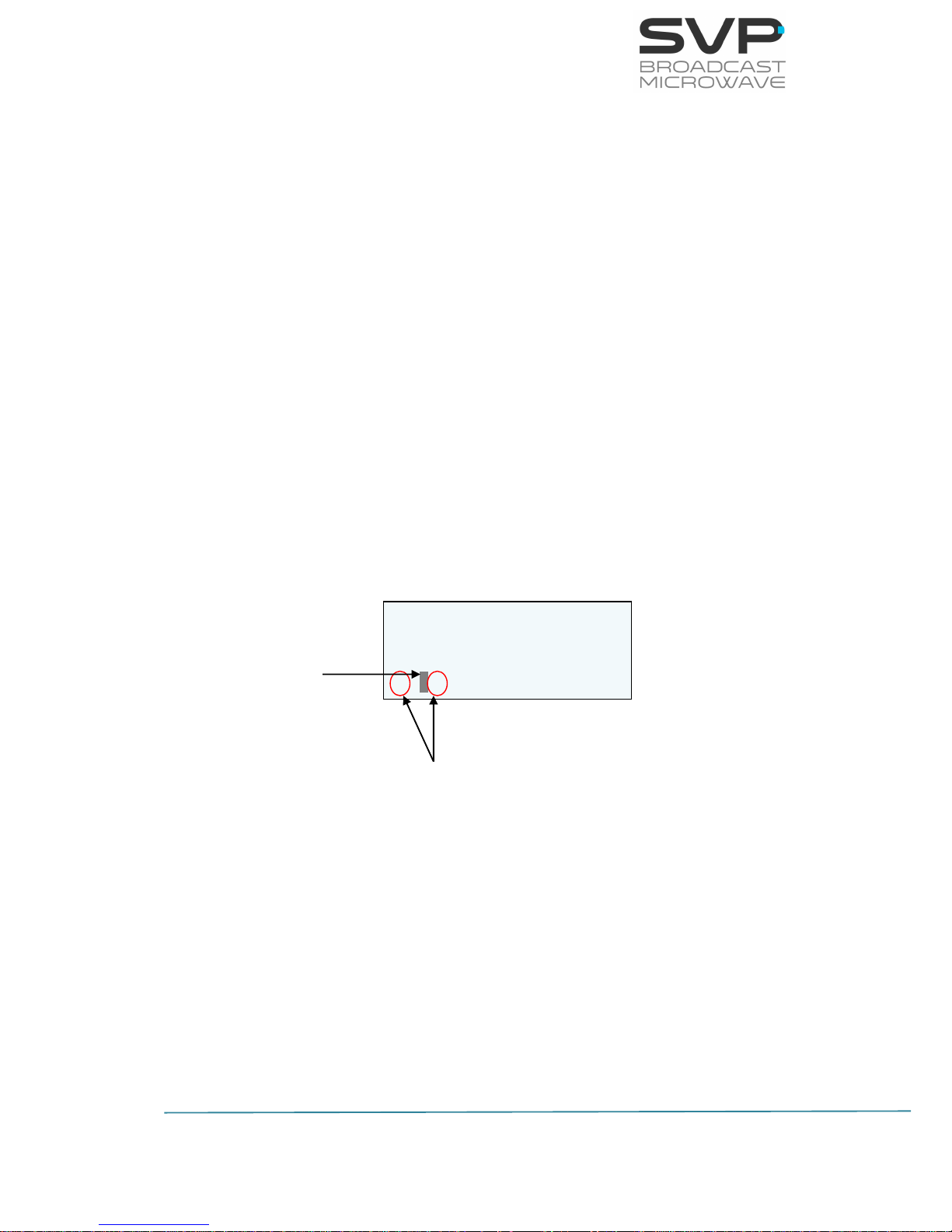
The Audio2 status indication is darkened because it is not enabled. If the
Audio2 is enabled, then this field would not be darkened.
When the data status field is enabled and blinkers, this means that there is
nothing connected to the data input. If it varies between a ‘G’ and a ‘g’ it
means that the GPS antenna is connected and it is trying to find three
localization satellites. If the ‘G’ does not vary, then it is connected to the
satellites.
F: 1500,000MHz DVBS2
P: +2.0 SR08.000 B10
16APSK 4/5 30.000Mb
HAUG 1080/50p 420S
darkened
blinking
Page 25

18
HENM-70 Encoder & DVB-S2/S Modulator
USER’S MANUAL V5.6
Example 2 (DVB-S2)
Setup:
Frequency: 1745.500 MHz
Transmission Standard: DVB-S2
Output power: +0 dBm
Symbol rate: 12.4 Msymb/s
Bandwidth: 16 MHz
Modulation Scheme: 32APSK
FEC: 8/9
Transmitted BitRate: 53.3 Mbps
Video input selection: SDI
Audio input selection: Audio1 embedded, Audio2 Analogue (both
enabled)
Data input selection: RS232
Input video signal format: 1080/50i
Padlock: BISS activated
Encoder Video Profile: 4.2.2
Latency: Standard
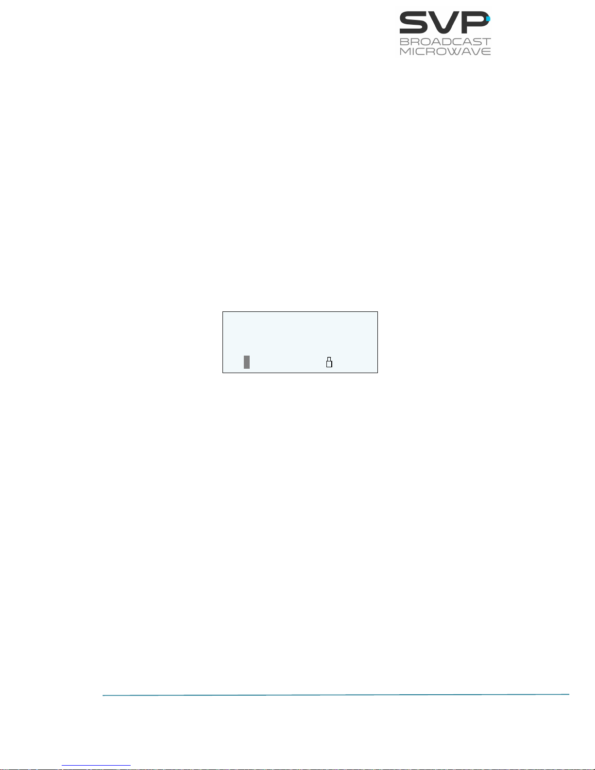
Figure 3.5 HENM-70 Main screen. Example 2
The input selection is not blinking because the device is receiving SDI (S)
video signal.
The Audio1 and Audio2 status indications are not darkened because both of
them are enabled. Letter ‘E’ corresponds to embedded and letter ‘A’ to
analogue.
The data input has been selected to RS232 so letter ‘D’ appears in the data
gap.
Before the encoder profile a padlock appears when the BISS encryption is
activated.
F: 1745,500MHz DVBS2
P: +0.0 SR12.400 B16
32APSK 8/9 53.300Mb
SEAD 1080/50i 422S
padlock
Page 26
19
HENM-70 Encoder & DVB-S2/S Modulator
USER’S MANUAL V5.6
Example 3 (DVB-S)
Setup:
Frequency: 1360.5 MHz (L band)
Transmission Standard: DVB-S
Output power: +3.0 dBm
Symbol rate: 8 Msymb/s
Bandwidth: 10 MHz
Modulation Scheme: QPSK
FEC: 7/8
Transmitted BitRate: 12.901Mbps
Video input selection: SDI
Audio inputs selection: Audio1 embedded, Audio2 None
Data input selection: UDP
Input video signal format: 1080/50i
Padlock: BISS activated
Encoder Video Profile: 4.2.0
Latency: Ultra Low Delay
Figure 3.6 HENM-70 Main screen. Example 3
F: 1360,500MHz DVBS
P: +3.0 SR08.000 B10
QPSK 7/8 12.901Mb
SEx 1080/50i 420UL
Page 27
20
HENM-70 Encoder & DVB-S2/S Modulator
USER’S MANUAL V5.6
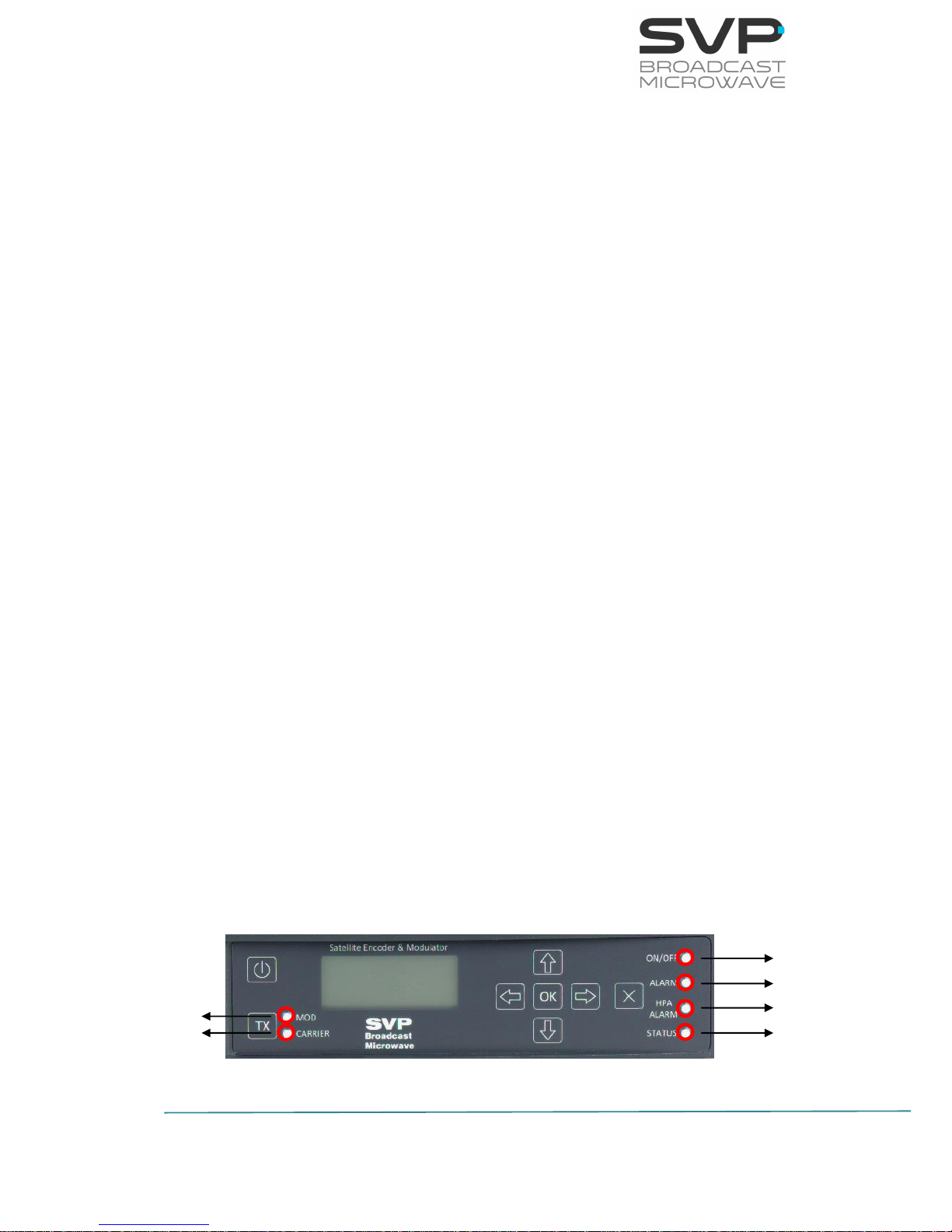
3.3 LEDs
The HENM-70 transmitter has 4 Leds on its front panel that show the
information detailed below.
The ON/OFF provides the following information:
If the Led is off, the equipment is not being fed.
If the Led flickers in red, there is power into the equipment but it is
turned off.
The Led lights up in green when the equipment is turned on.
The ALARM LED provides the following information:
The LED lights up in red when any alarm occurs.
The different alarms that can appear in the transmitter are:
- Voltage High or Low.
- Temperature High.
- ASI Overflow: This alarm means that the input bitrate is higher than
the one that can be modulated due to the parameters configured
(constellation, FEC, GI...).
The different warnings that can appear in the transmitter are:
- No Video Input.
- No GPS.
The HPA ALARM LED provides the following information:
The LED lights up in green when a BUC is connected to the HDT-70. It is
used in satellite transmission standards.
The STATUS LED:
The LED lights up when a change in the configuration of the device is
being processed.
MOD LED and CARRIER LED:
These LEDs light up when DVB-S2 transmission standard is being used.
Figure 3.7 HENM-70 front panel/ LED explanation
ON/OFF LED
ALARM LED
ALARM LED
STATUS LED
MOD LED
CARRIER LED
Page 28
21
HENM-70 Encoder & DVB-S2/S Modulator
USER’S MANUAL V5.6
3.4 Front panel
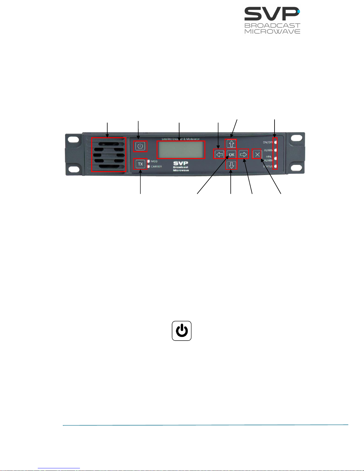
The HENM-70 encoder and modulator is configured following a menus
structure on the display. The front panel has 8 buttons to enter and exit the
equipment control menus and submenus and to navigate through them. The
function of each button is detailed in the following sections.
Figure 3.8 HENM-70 front panel
3.4.1 ON/OFF Button
To switch the equipment on and off, press this button. When the equipment
is turned on, the display will show the start-up message (model and version
of the equipment), and then it will display the main screen.
If the power fails while the equipment is operating, it will restart
automatically when the power returns, not being necessary to press the
on/off button again.
Figure 3.9 ON/OFF button
OK
Button
UP
Button
Cross
Button
Fan
Display
Left
Button
UP
Button
Right
Button
OK
Button
Down
Button
Cross
Button
ON/OFF
Button
LEDs
TX
Button
Page 29

22
HENM-70 Encoder & DVB-S2/S Modulator
USER’S MANUAL V5.6
3.4.2 OK Button
This button is used to:
Enter to submenus and change parameters. So as to access to a
submenu, the OK button must be pressed. Moreover, in the fields where
the enter symbol appears, by pressing the OK button the user can
change the value of the selected parameter. Besides, so as to save the
introduced value, the OK button must be pressed.
In case of being in the main screen, pressing the OK button, the user
can access to the alarms screen where there are different alarms that
are taking place. So as to return to the main screen, the cross button
must be pressed.
Figure 3.10 OK button
3.4.3 Cross Button
This button is used to:
Enter from the HENM-70 main screen to the setup menu and vice versa.
Exit equipment submenus.
This button allows the user to access to the main screen from the alarms
screen.
Figure 3.11 Cross button
OK
X
Page 30
23
HENM-70 Encoder & DVB-S2/S Modulator
USER’S MANUAL V5.6
3.4.4 Left and Right Button
These buttons are used to:
Once the parameter to change has been selected, they are used to move
the cursor towards the digit immediately on the left or right and to select
a parameter from different options.
Figure 3.12 Left and Right buttons
3.4.5 Up and Down Button
The up and down arrow buttons allow navigation in the main menu and
the rest of submenus. Using these buttons the user can enter to the
submenu or change a parameter. Once selected, the OK button must be
pressed.
These buttons are also used to change, for example, the frequency and
PID parameters values. Pressing up and down arrows the value of those
parameters can be changed, increased or decreased respectively.
Figure 3.13 Up and Down buttons
Page 31

24
HENM-70 Encoder & DVB-S2/S Modulator
USER’S MANUAL V5.6
3.5 Menus
There is one menu in this device that allows the operator to change the
HENM-70 parameters and to configure them.
To enter the menu of this equipment cross button must be pressed.
In case it is wanted to return again to the principal screen from the menu,
cross button must be pressed. Furthermore, in case of being in the
submenus area, returning to the mainly screens is achieved by pressing the
cross button as much times as it is needed.
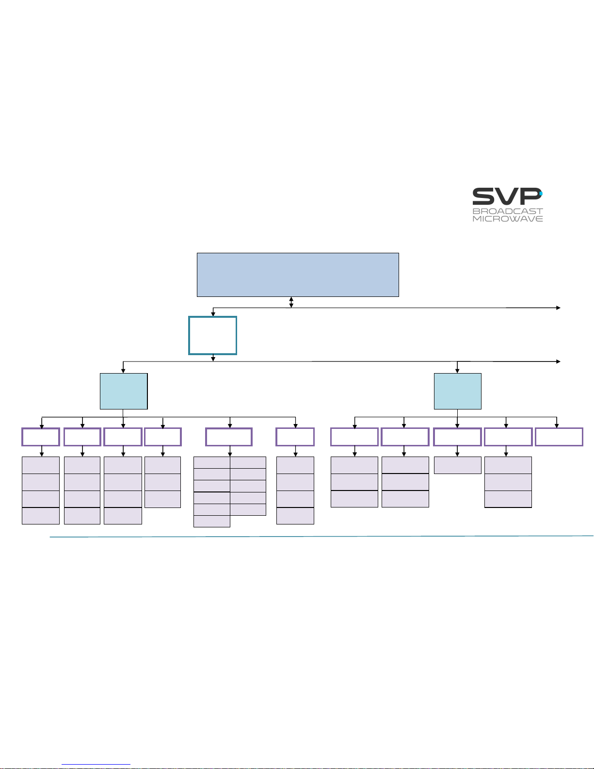
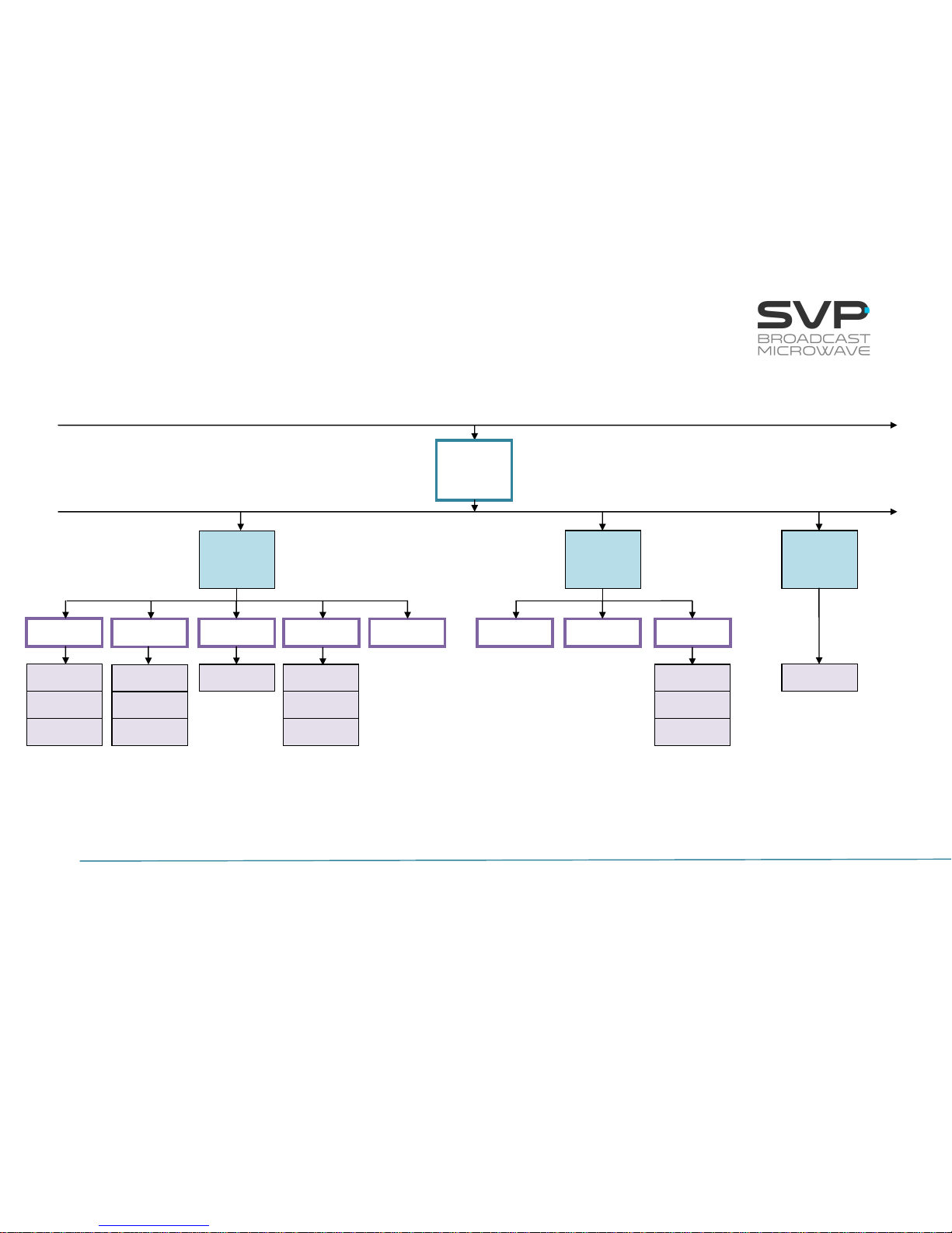
In the next page it is shown a scheme that specifies the different menu
options available.
Page 32
25
HENM-70 Encoder & DVB-S2/S Modulator
USER’S MANUAL V5.6
HENM_70 MENU STRUCTURE
continued
MAIN SCREEN
Frequency, standard, power, FFT, bandwidth,
modulation, FEC,GI, latency, output bitrate,
audio and video status, profile
Format
Encoder
Video
SDI
HDMI
CVBS
ASI
IP
GEN
L Type
Format
Status
Format
Delay
Profile
Delay
Profile
Profile
Delay
Format
Bitrate
Profile
Delay
Analogue
Embedded
AES-EBU
Tone.Gen
None
Audio 1
Bitrate
Bitrate
Bitrate
Bitrate
Frequency
Level
continued
Format
Local IP
Protocol
Fec
Port
Out.Delay
TP per IP
Status
IP.Adr
BitRate
PCR
Packet Size
GOP
GOP
GOP
GOP
R Type
Gp
DID
Page 33
26
HENM-70 Encoder & DVB-S2/S Modulator
USER’S MANUAL V5.6
DID
continued
continued
continued
continued
Audio 2
Data
Analogu
Embedded
AES-EBU
Tone.Gen
None
None
GPS
RS232
Bitrate
L Type
Bitrate
Bitrate
Bitrate
Frequency
Level
BaudRate
Parity
Stop Bits
Encoder
Output
Bitrate
Encoder
R Type
Gp
DID
Page 34
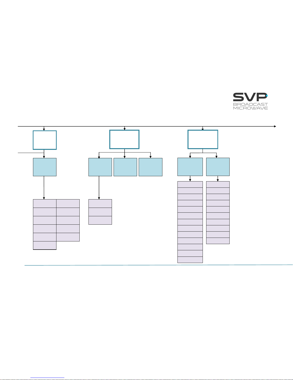
27
HENM-70 Encoder & DVB-S2/S Modulator
USER’S MANUAL V5.6
continued
continued
Roll Off
Freq
Power
Modulator
Antenna Gain
Bandwidth
LDPC FEC
SR
10 MHz
Modulator
DVB-S2
continued
TS
Parameters
Video PID
Audio1 PID
PMT PID
PCR PID
Data PID
Program Nº
Network
Name
Audio2 PID
TS id
Network id
Service Name
Mode
SW User
None
BISS-1
BISS-E
Encoder
CA-BISS
Spectrum
Pilots
DVB-S
Freq
Power
Bandwidth
FEC
SR
10 MHz
Spectrum
BUC LO
Modul
Modulator
BUC LO
Antenna Gain
Page 35
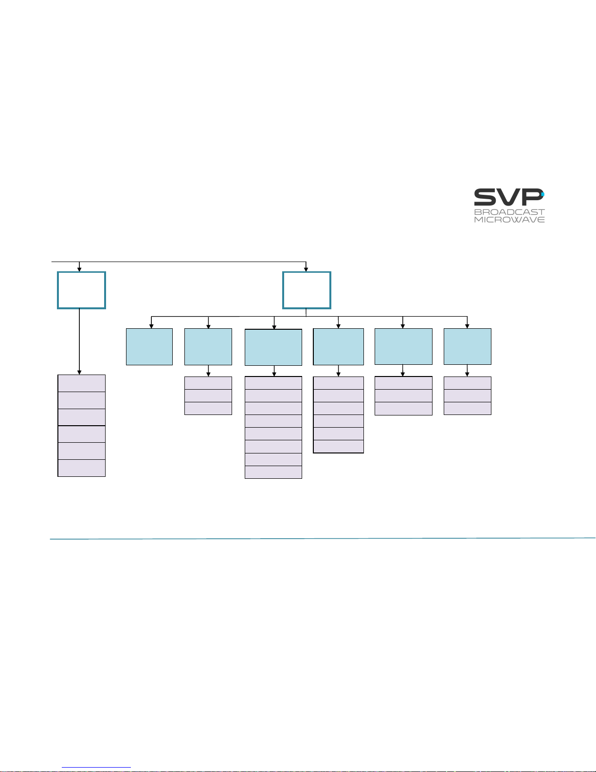
28
HENM-70 Encoder & DVB-S2/S Modulator
USER’S MANUAL V5.6
continued
Self Check
Temperature
Voltage
Local IP
Mask
Gateway
Unit
Alarms
Monitor
Webserver
& SNMP
Miscellaneous
Firmware
IP Out
DestinationIP
&Port
Fec
Local IP
TP per IP
TTL
Protocol
BUC S/S2
Unit
MAC
Admin Pass
Rectore Admin Pass
User Pass
Rectore User Pass
Keyboard Beep
Keyboard Lock
Night Mode
Dist Units
S/N
Update Firmware
Restore Default
Rv
Alarms
Temp
Type
MAC
Page 36
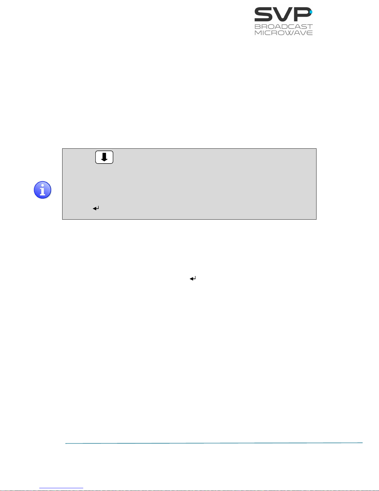
29
HENM-70 Encoder & DVB-S2/S Modulator
USER’S MANUAL V5.6
3.5.1 Menu Navigation
This section contains a detailed description of each parameter that can be
configured in the HENM-70 encoder and DVB-S2/S modulator via the MENU.
To enter the MENU, press the cross button in case of being in the main
screen or in any submenu.
To select a parameter or a submenu use the Up, Down arrows. Once
selected, press the OK button to access to a submenu or to edit a
parameter. To exit a submenu or a parameter, press the cross button.
Figure means that to have access to the right image that button
must be pushed.
Symbols <> mean that the parameter can be modified in the same screen
with the right and left keys.
Symbol means that pushing the OK button allows entering to the options
of the submenu.
Different types of parameters are available:
- Eligible: When the user can choose between predetermined
states. (They usually have the symbol <> near to them)
- Editable: When the user must enter a value in that option. (They
usually have the symbol near them). So as to save the
introduced value, the OK button must be pressed.
- Reading: When the value of that parameter is a monitored
parameter that can’t be changed.
To change a parameter, e.g. the transmitted frequency, press the OK
button in the desired option and then with the Up, Down buttons choose the
value. Once the parameter is set, press the OK button so as to save the
value.
Next, the different menus and submenus with the options and eligible
parameters are shown. Also, in each figure, example parameters are
shown.
Page 37

30
HENM-70 Encoder & DVB-S2/S Modulator
USER’S MANUAL V5.6
3.5.2 Menu Structure
The following menu screen can be accessed by pressing the cross key from
the monitoring menu.
Figure 3.14 Menu
Encoder – All the parameters related to the video, audio and data inputs
are configured here. Besides, all video, audio, data encoding and
multiplexing parameters are accessed here.
CA-BISS – The encryption of signals can be configured in this option.
Modulator – DVB - S2/S transmission parameters are set in this section.
IP Out – All the parameters related to the IP output are configured in this
section.
Unit – Parameters related to the Web Server and other internal options of
the HENM-70 are configured here, as well as other characteristics.
MAIN MENU
Encoder Modulator
CA-BISS IP Out
Unit
Page 38
31
HENM-70 Encoder & DVB-S2/S Modulator
USER’S MANUAL V5.6
3.5.2.1 Encoder Menu
By using the Up, Down arrow keys, select the Encoder option and press the
OK key.
Figure 3.15 Encoder Menu
Line nº
Function
1
Video:
In this field, the video input must be chosen with the Right and Left
buttons. Once the video input has been selected, press the OK
button so as to configure the parameters related to it.
The available options are:
SDI
HDMI
CVBS
ASI
IP
GEN
2
Audio 1:
In this field, the sort of audio input through the channel number 1
can be chosen with right and left buttons. Once the audio 1 input
has been selected, press the OK button so as to configure the
parameters related to it.
The available options are:
Embedded
Analogue
AES-EBU
Tone.Gen
None
ENCODER
Video: SDI >
Audio1: Tone.Gen <>
Audio2: AES-EBU <>
ENCODER
Data: GPS <>
Encoder Output
TS Parameters
Page 39

32
HENM-70 Encoder & DVB-S2/S Modulator
USER’S MANUAL V5.6
3
Audio 2:
In this field, the sort of audio input through the channel number 2
can be chosen with right and left buttons. Once the audio 2 input
has been selected, press the OK button so as to configure the
parameters related to it.
The available options are:
Embedded
Analogue
AES-EBU
Tone.Gen
None
4
Data:
In this field, the sort of data input can be selected.
The available options are:
None
GPS
RS-232
5
Encoder Output:
In this field, the encoder output can be selected. Pressing the OK
button, the output bitrate can be configured.
6
TS Parameters:
This file consists on the configuration of the parameters of the
Transport Stream. In this option, the different program identifiers
are configured.
Table 3.4 Encoder Menu options
Page 40

33
HENM-70 Encoder & DVB-S2/S Modulator
USER’S MANUAL V5.6
3.5.2.1.1 SDI Input
Figure 3.16 SDI Input Menu
Line nº
Function
1
Format (SDI):
In this field, the format of the SDI input signal is displayed. (reading
parameter)
The available options are:
1080p (1920x1080) – 23.98/24/25/29.97/30/50/59.94/60 Hz
1080i (1920x1080) – 50/59.94/60 Hz
720p (1280x720) – 23.98/24/25/29.97/30/50/59.94/60 Hz
576i (720x576) – 50 Hz
480i (720x480) – 59.94 Hz
2
Delay:
In this field, the delay of the coding process is configured. So as to
select the desired delay, press Right, Left arrows buttons. (eligible
parameter)
The available options are:
Standard
Low Delay (3 frames of delay)
SuperLD (2 frames of delay)
Ultra Low Delay (1 frame of delay)
3
Profile:
In this field, the codification profile can be configured. So as to
select the desired profile, press Right, Left arrows buttons. (eligible
parameter)
The available options are:
4.2.2
4.2.0
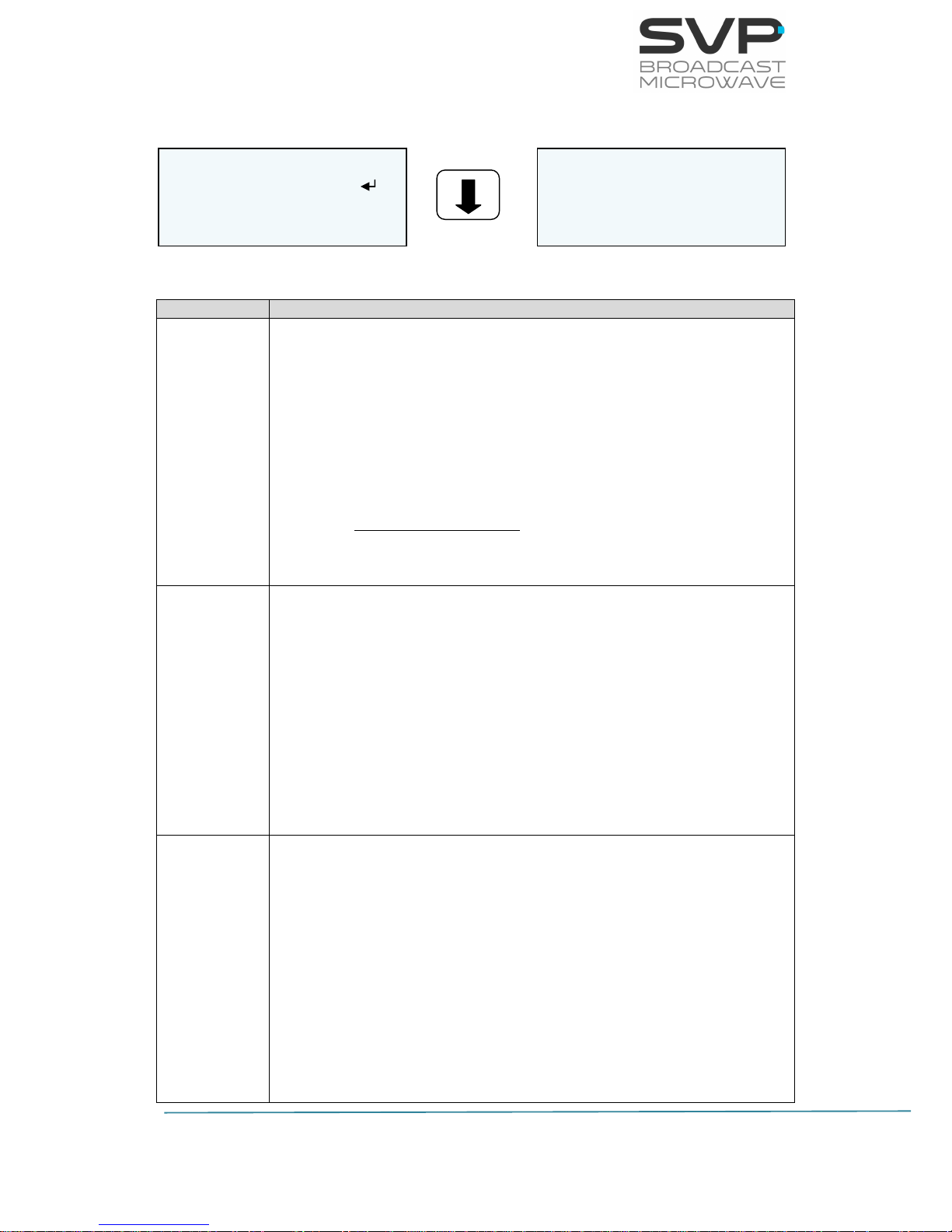
ENCODER VIDEO SDI
Format: 1080/50i
Delay: SuperLD 2F <>
Profile: 4.2.0 >
ENCODER VIDEO SDI
GOP: Auto 12 <>
Page 41
34
HENM-70 Encoder & DVB-S2/S Modulator
USER’S MANUAL V5.6
4
GOP:
In this field, the group of figures parameter is displayed. It specifies
the order in which intra- and inter-frames are arranged. (eligible
parameter)
The available options are:
Auto
Manual (editable parameter)
Table 3.5 SDI Input menu options
In case HDMI video input is selected, it is necessary to specify the format
(1080p, 1080i, 720p). If other video input (SDI, CVBS or ASI) is selected,
then the transmitter automatically captures its format and the frame rate. If
the video format is changed, the time detection of this new format is less
than 15 seconds.
Page 42
35
HENM-70 Encoder & DVB-S2/S Modulator
USER’S MANUAL V5.6
3.5.2.1.2 HDMI Input
Figure 3.17 HDMI Input Menu
Line nº
Function
1
Format:
In this field, the format of the HDMI input signal must be selected.
So as to select a format, first, press the OK button so as to enter to
the submenus where different formats available appear. Then,
choose the desired option with the UP, Down keys. (editable
parameter)
The available options are:
1080p (Only Standard Delay)
1080i
720p
2
Delay:
In this field, the delay of the coding process is configured. So as to
select the desired delay, press Right, Left arrows buttons. (eligible
parameter)
The available options are:
Standard
Low Delay (3 frames of delay)
SuperLD (2 frames of delay)
Ultra Low Delay (1 frame of delay)
3
Profile:
In this field, the codification profile can be configured. So as to
select the desired profile, press Right, Left arrows buttons. (editable
parameter)
The available options are:
4.2.0
4.2.2
ENCODER VIDEO HDMI
Format: 1080p
Delay: Standard >
Profile: 4.2.2 <
ENCODER VIDEO HDMI
GOP: Auto 12 >
Page 43

36
HENM-70 Encoder & DVB-S2/S Modulator
USER’S MANUAL V5.6
4
GOP:
In this field, the group of figures parameter is displayed. It specifies
the order in which intra- and inter-frames are arranged. (eligible
parameter)
The available options are:
Auto
Manual (editable parameter)
Table 3.6 HDMI Input menu options
Page 44

37
HENM-70 Encoder & DVB-S2/S Modulator
USER’S MANUAL V5.6
3.5.2.1.3 CVBS Input
Figure 3.18 CVBS Input Menu
Line nº
Function
1
Format (CVBS):
In this field, the format of the CVBS input signal is displayed.
(reading parameter)
The available options are:
480i
576i
2
Delay:
In this field, the delay of the coding process is configured. So as to
select the desired delay, press Right, Left arrows buttons. (eligible
parameter)
The available options are:
Standard
Low Delay (3 frames of delay)
SuperLD (2 frames of delay)
Ultra Low Delay (1 frame of delay)
3
Profile:
In this field, the codification profile can be configured. So as to
select the desired profile, press Right, Left arrows buttons. (eligible
parameter)
The available options are:
4.2.0
4.2.2
ENCODER VIDEO CVBS
Format: 480i
Delay: SuperLD 2F <>
Profile: 4.2.0 >
ENCODER VIDEO CVBS
GOP: Auto 12 >
Page 45

38
HENM-70 Encoder & DVB-S2/S Modulator
USER’S MANUAL V5.6
4
GOP:
In this field, the group of figures parameter is displayed. It specifies
the order in which intra- and inter-frames are arranged. (eligible
parameter)
The available options are:
Auto
Manual (editable parameter)
Table 3.7 CVBS Input menu options
Page 46

39
HENM-70 Encoder & DVB-S2/S Modulator
USER’S MANUAL V5.6
3.5.2.1.4 ASI Input
Figure 3.19 ASI Input Menu
Line nº
Function
1
Status:
This field indicates if there is any ASI signal in the ASI input. In case
there is an ASI signal, this field will display the word present. If
there is no ASI signal then, no present will be displayed. (reading
parameter)
The available options are:
Present
No Present
2
Bitrate:
In this field, the bitrate of the ASI input signal is shown. (reading
parameter)
3
Format:
In this field, the format of the ASI input signal is shown. (reading
parameter)
The available options are:
188 bytes
204 bytes
Table 3.8 ASI Input menu options
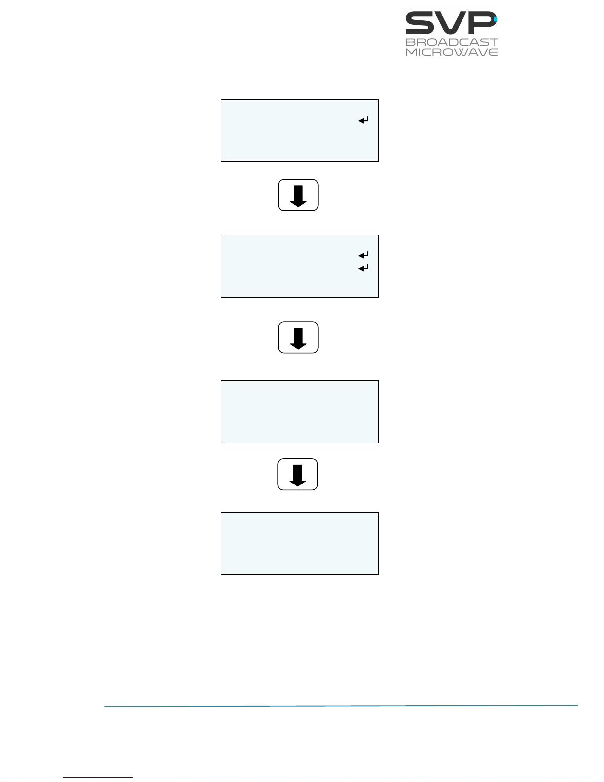
ASI INPUT
Status: Present
Bitrate: 18.0Mb
Format: 188
Page 47
40
HENM-70 Encoder & DVB-S2/S Modulator
USER’S MANUAL V5.6
3.5.2.1.5 IP Input
Figure 3.20 IP Input Menu
IP INPUT
Local IP
IP.Adr: Unicast >
Fec: Disable >
IP INPUT
Port: 5600
Out. Delay: 128 ms
TP per IP: 1
IP INPUT
Status: ENABLE
Protocol: UDP
Packet Size: 188
IP INPUT
BitRate: 0.00Mb
PCR: No Present
Page 48

41
HENM-70 Encoder & DVB-S2/S Modulator
USER’S MANUAL V5.6
Line nº
Function
1
Local IP:
So as to configure the network parameters, press the OK button.
(editable parameters)
The available options are:
Local IP:
So as to establish the Local IP address, press the OK button and
then, with the UP, Down buttons change the value. If the user
wants to change from one character to another, press the Right,
Left buttons. So as to save the introduced value, press the OK
button. If this IP is the same as the IP for remote control
(Webserver / SNMP), the device shows a warning message.
Mask:
In this field the Subnet Mask address must be specified. So as to
establish the Subnet Mask address, press the OK button and
then, with the UP, Down buttons change the value. If the user
wants to change from one character to another, press the Right,
Left buttons. So as to save the introduced value, press the OK
button.
Gateway:
In this field the Gateway address must be specified. So as to
establish the Gateway address, press the OK button and then,
with the UP, Down buttons change the value. If the user wants
to change from one character to another, press the Right, Left
buttons. So as to save the introduced value, press the OK
button.
MAC:
The MAC Address of the transmitter is shown. (reading
parameter)
2
IP.Adr:
So as to select the short of address from which IP information is
received, press Right, Left buttons. (eligible parameters)
The available options are:
Unicast:
In case it is wanted to receive the signal from any single IP
address to this device, unicast option must be chosen.
Multicast:
In case the signal is received from a multicast address, that
multicast address must be configured in this field. So as to enter
the multicast address, press the OK button so as to be able to
configure the multicast address. (editable parameter)
Page 49

42
HENM-70 Encoder & DVB-S2/S Modulator
USER’S MANUAL V5.6
3
Fec:
So as to select if FEC is enabled or disabled in the received signal
press Right, Left buttons. (eligible parameter)
The available options are:
Enable Col: Row: (The IP Forward Error Correction is
composed by a number of FEC columns and rows. In this field it
is shown the number of FEC columns and rows of the received
signal) (reading parameter)
Disable
4
Port:
This field must be filled in with the port number of the decoder
device through which is going to receive the signal. So as to edit this
parameter, press the OK button and then, select the desired port
with the Up, Down, or Right, Left buttons. So as to save the
introduced value, press the OK button. (editable parameter)
5
Output Delay [1..9942]ms:
This delay means the time passed between the Transport Stream is
obtained in the decoder and the signal is taken out from the
decoder. So as to edit this parameter, press the OK button and then,
select the desired port with the Up, Down and Right, Left buttons.
So as to save the introduced value press the OK button. (editable
parameter)
6
TP per IP:
This field displays the number of TS packets per IP packet. (reading
parameter)
7
Status:
This field displays the status of the IP input. (reading parameter)
8
Protocol:
This field displays the protocol used for the communication. (reading
parameter)
The possible options are:
UDP
RTP
Page 50

43
HENM-70 Encoder & DVB-S2/S Modulator
USER’S MANUAL V5.6
9
Packet Size:
This field shows the size in bytes of the IP received packets.
(reading parameter)
10
BitRate:
This field displays the bitrate of the received signal. (reading
parameter)
11
PCR:
Program Clock Reference. To enable a decoder to present
synchronized content, such as audio tracks matching the associated
video, at least once each 100 ms a Program Clock Reference, or PCR
is transmitted in the adaptation field of an MPEG-2 transport stream
packet. The parameters displayed can be present or no present.
(reading parameter)
Table 3.9 IP Input Select menu option
Page 51
44
HENM-70 Encoder & DVB-S2/S Modulator
USER’S MANUAL V5.6
3.5.2.1.6 Generator Input
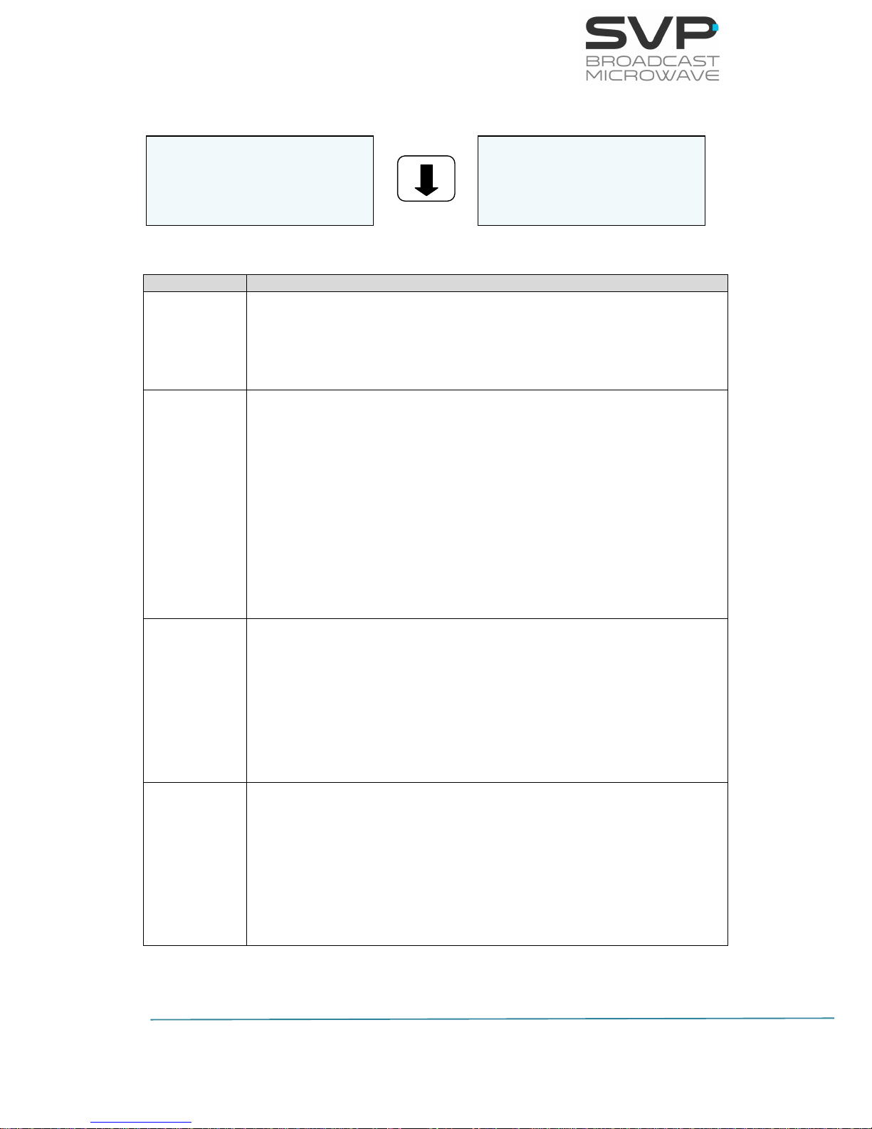
Figure 3.21 Generator Input Menu
Line nº
Function
1
Format:
In this field the format of the video signal generated is displayed.
The only option available is 576/50i. (reading parameter)
2
Delay:
In this field, the delay of the coding process is configured. So as to
select the desired delay, press Right, Left arrows buttons. (eligible
parameter)
The available options are:
Standard
Low Delay (3 frames of delay)
SuperLD (2 frames of delay)
Ultra Low Delay (1 frame of delay)
3
Profile:
In this field, the codification profile can be configured. So as to
select the desired profile, press Right, Left arrows buttons (eligible
parameter). The available options are:
4.2.0
4.2.2
4
GOP:
In this field, the group of figures parameter is displayed. It specifies
the order in which intra- and inter-frames are arranged (eligible
parameter). The available options are:
Auto
Manual (editable parameter)
Table 3.10 Generator Input menu options
ENCODER VIDEO GEN
Format: 576/50i
Delay: SuperLD 2F <>
Profile: 4.2.0 >
ENCODER VIDEO GEN
GOP: Auto 12 >
Page 52

45
HENM-70 Encoder & DVB-S2/S Modulator
USER’S MANUAL V5.6
3.5.2.1.7 Audio1 Embedded
Figure 3.22 Audio Embedded Input Menu
Line nº
Function
1
Bitrate:
In this option the bitrate for the codification of the audio signal 1 can
be selected. So as to select the desired bitrate, press Right, Left
arrows buttons. (eligible parameter)
The available options are:
128K
192K
256K
384K
2
Group:
In this field the different numbers of input groups are displayed. In
case one group is not present then, a line will appear. (reading
parameter)
DID:
In this field, the desired group can be selected. So as to select the
group, press Right, Left buttons. (eligible parameter)
The available options are:
G0
G1
G2
G3
Table 3.11 Audio Embedded Input menu options
If the video option selected is CVBS, ASI, IP or Test Pattern generator then,
the option of audio embedded will be blinking because that configuration is
not possible.
ENCODER AUDIO1
Bitrate:256K <>
Gp: (1234) DID:G0 <>
Page 53

46
HENM-70 Encoder & DVB-S2/S Modulator
USER’S MANUAL V5.6
3.5.2.1.8 Audio1 Analogue
Figure 3.23 Audio Analogue Input Menu
Line nº
Function
1
Bitrate:
In this option, the bitrate for the codification of the audio signal 1
can be selected. So as to select the desired bitrate, press Right, Left
arrows buttons. (eligible parameter)
The available options are:
128K
192K
256K
384K
2
L Type:
In this field, the sort of signal of the audio 1 left channel introduced
in the device is selected. So as to choose the type of audio1, press
Right, Left buttons. (eligible parameter)
The available options are:
Line
Mic Dynamic
Mic Phantom
3
R Type:
In this field, the sort of signal of the audio 1 right channel
introduced in the device is selected. So as to choose the type of
audio 1, press Right, Left buttons. (eligible parameter)
The available options are:
Line
Mic Dynamic
Mic Phantom
Table 3.12 Audio Analogue Input menu options
ENCODER AUDIO1
Bitrate:256K <>
L Type: Line >
R Type: Line >
Page 54

47
HENM-70 Encoder & DVB-S2/S Modulator
USER’S MANUAL V5.6
3.5.2.1.9 Audio1 AES-EBU
Figure 3.24 Audio AES-EBU Input Menu
Line nº
Function
1
Bitrate:
In this option, the bitrate for the codification of the audio signal 1
can be selected. So as to select the desired bitrate, press Right, Left
arrows buttons. (eligible parameter)
The available options are:
128K
192K
256K
384K
Table 3.13 Audio AES-EBU Input menu options
ENCODER AUDIO1
Bitrate: 384K <
Page 55

48
HENM-70 Encoder & DVB-S2/S Modulator
USER’S MANUAL V5.6
3.5.2.1.10 Audio1 Tone.Gen
Figure 3.25 Audio Generator Input Menu
Line nº
Function
1
Bitrate:
In this option, the bitrate for the codification of the audio signal 1
can be selected. So as to select the desired bitrate, press Right, Left
arrows buttons. (eligible parameter)
The available options are:
128K
192K
256K
384K
2
Frequency (Hz):
In this field, the frequency of the generated tone is displayed.
(reading parameter)
3
Level (dBFs):
In this field, the level in dBF of the generated tone is displayed.
(reading parameter)
Table 3.14 Audio Generator Input menu options
ENCODER AUDIO1
Bitrate:384K <
Frequency: 1000Hz
Level: 18dBFs
Page 56

49
HENM-70 Encoder & DVB-S2/S Modulator
USER’S MANUAL V5.6
3.5.2.1.11 Audio2 Embedded
Figure 3.26 Audio Embedded Input Menu
Line nº
Function
1
Bitrate:
In this option, the bitrate for the codification of the audio signal 2
can be selected. So as to select the desired bitrate, press Right, Left
arrows buttons. (eligible parameter)
The available options are:
128K
192K
256K
384K
2
Group:
In this field the different numbers of input groups are displayed. In
case one group is not present then, a line appears. (reading
parameter)
DID:
In this field it can be selected the desired group. So as to select the
group, press Right, Left buttons. (eligible parameter)
The options available are:
G0
G1
G2
G3
Table 3.15 Audio Embedded Input menu options
If the video option selected is CVBS, ASI, IP or Test Pattern Generator then,
the option of audio embedded will be blinking because that configuration is
not possible.
ENCODER AUDIO2
Bitrate:256K <>
Gp: (1234) DID:G0 <>
Page 57

50
HENM-70 Encoder & DVB-S2/S Modulator
USER’S MANUAL V5.6
3.5.2.1.12 Audio2 Analogue
Figure 3.27 Audio Analogue Input Menu
Line nº
Function
1
Bitrate:
In this option, the bitrate for the codification of the audio signal 2
can be selected. So as to select the desired bitrate, press Right, Left
arrows buttons. (eligible parameter)
The available options are:
128K
192K
256K
384K
2
L Type:
In this field, the sort of signal of the audio 2 left channel introduced
in the device is selected. So as to choose the type of audio 2, press
Right, Left buttons. (eligible parameter)
The available options are:
Line
Mic Dynamic
Mic Phantom
3
R Type:
In this field, the sort of signal of the audio 2 right channel
introduced in the device is selected. So as to choose the type of
audio 2, press Right, Left buttons. (eligible parameter)
The available options are:
Line
Mic Dynamic
Mic Phantom
Table 3.16 Audio Analogue Input menu options
ENCODER AUDIO2
Bitrate:256K <>
Type: Line <>
Page 58

51
HENM-70 Encoder & DVB-S2/S Modulator
USER’S MANUAL V5.6
3.5.2.1.13 Audio2 AES-EBU
Figure 3.28 Audio AES-EBU Input Menu
Line nº
Function
1
Bitrate:
In this option the bitrate for the codification of the audio signal 2 can
be selected. So as to select the desired bitrate, press Right, Left
arrows buttons. (eligible parameter)
The available options are:
128K
192K
256K
384K
Table 3.17 Audio AES-EBU Input menu options
ENCODER AUDIO2
Bitrate:384K <
Page 59

52
HENM-70 Encoder & DVB-S2/S Modulator
USER’S MANUAL V5.6
3.5.2.1.14 Audio2 Tone.Gen
Figure 3.29 Audio Generator Input Menu
Line nº
Function
1
Bitrate:
In this option, the bitrate for the codification of the audio signal 2
can be selected. So as to select the desired bitrate, press Right, Left
arrows buttons. (eligible parameter)
The available options are:
128K
192K
256K
384K
2
Frequency (Hz):
In this field, the frequency of the generated tone is displayed.
(reading parameter)
3
Level (dBFs):
In this field, the level in dBF of the generated tone is displayed.
(reading parameter)
Table 3.18 Audio Generator Input menu options
ENCODER AUDIO2
Bitrate: 384K <
Frequency: 1000Hz
Level: 18dBFs
Page 60
53
HENM-70 Encoder & DVB-S2/S Modulator
USER’S MANUAL V5.6
3.5.2.1.15 Data
So as to select the desired sort of data, press Right, Left buttons. (eligible
parameter)
The available options are:
None
GPS
RS232
None
This option is selected in case no data is sent to the device.
Figure 3.30 None screen
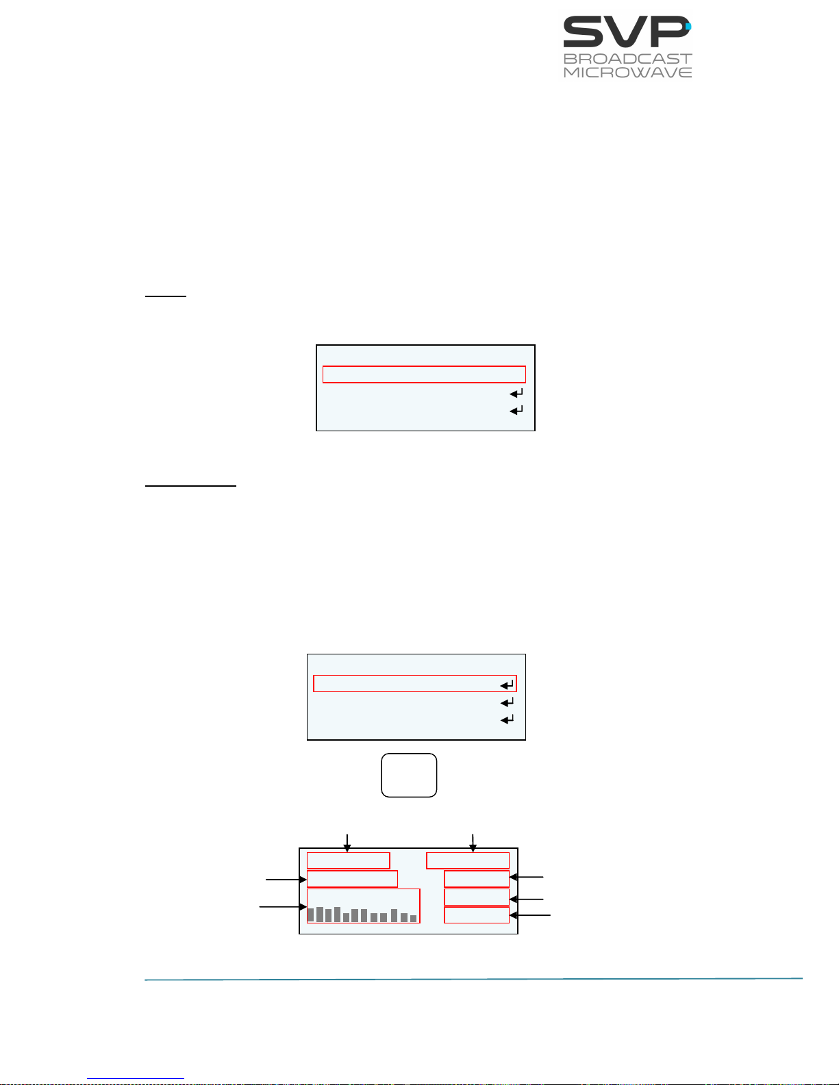
GPS Screen
IF this option is selected and the GPS antenna is connected to the GPS input
of the device then, by pressing the OK button, the user can access to the
different parameters sent by the GPS.
So as to access to the GPS screen first, go to the encoder option in the
menu. Then, go to the Data option and select GPS with the Right, Left keys.
Next, press the OK button so as to access to the GPS screen. Below, there
are shown the different parameters which appear in the GPS screen.
Figure 3.31 GPS screen
#--º--.---´ ---k ---º
#---º--.---´ -----mt
Satellite Level --/--/--
--:--:--
Level of the satellite signals
Time
Date
Height (meters)
Speed(knot)/
Direction(degrees)
Longitude of the
HENM-70
Latitude of the
HENM-70
ENCODER
Data: None <
Encoder Output
TS Parameters
ENCODER
Data: GPS <>
Encoder Output
TS Parameters
OK
Page 61
54
HENM-70 Encoder & DVB-S2/S Modulator
USER’S MANUAL V5.6
Next there are shown the different fields meanings.
Latitude of the HENM-70: It specifies the latitude position of the
device.
Speed of the HENM-70: It shows the speed of the HENM-70 in knot.
Direction of the HENM-70: The direction of the device is shown in this
field.
Longitude of the HENM-70: It specifies the longitude position of the
device.
Height of the HENM-70: The height of the transmitter from ground is
specified in this value.
Satellite Level: The level of each satellite signal received is shown in
this field.
Date: The updated date is shown.
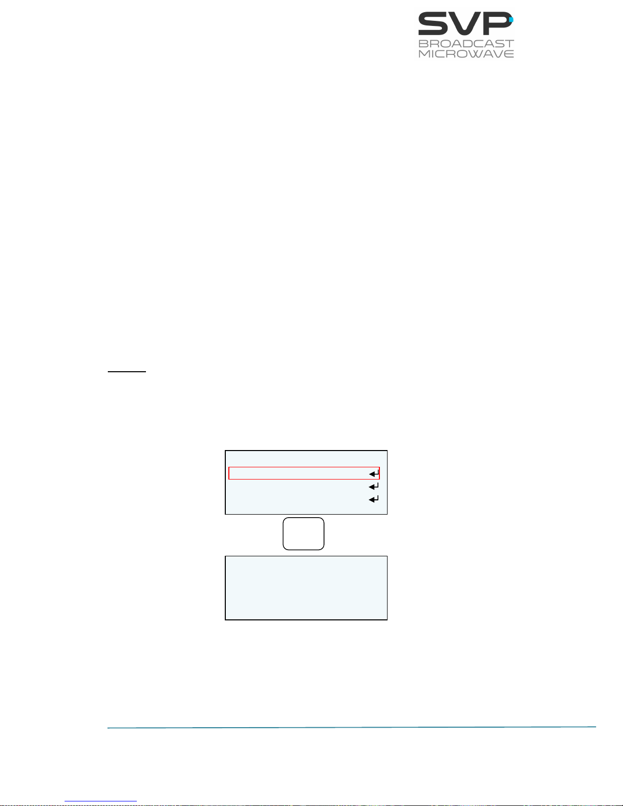
RS232
If it is wanted to send data to the device through a RS232 connection, this
option must be selected. It is also needed to configure the next parameters
so as to achieve a successful communication.
Figure 3.32 RS232 screen
ENCODER
Data: RS232 <
Encoder Output
TS Parameters
OK
DATA INPUT RS232
BaudRate: 57600 <
Parity: None >
Stop Bits: 1 >
Page 62

55
HENM-70 Encoder & DVB-S2/S Modulator
USER’S MANUAL V5.6
Data option
Parameters
1
BaudRate:
Select the baudrate at which data user is received. (Baudrate
options are: 1200, 2400, 4800, 9600, 19200, 38400, 57600)
(eligible parameters)
2
Parity:
Select the same parity as the parity of the received data user signal.
(Parity options are None, Even, Odd) (eligible parameters)
3
Stop Bits:
Select the same number of stop bits as the received data user signal
has. (Stop bit options are 1 or 2) (eligible parameter)
Table 3.19 Data Parameters
Page 63
56
HENM-70 Encoder & DVB-S2/S Modulator
USER’S MANUAL V5.6
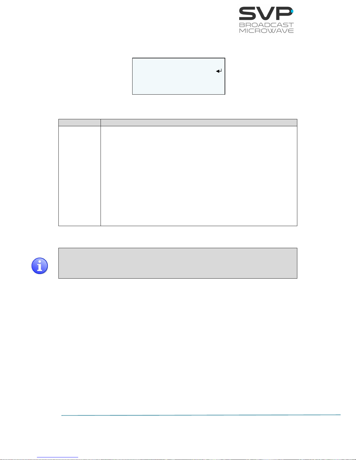
3.5.2.1.16 Encoder Output
Figure 3.33 Encoder Output Menu
Line nº
Function
1
BitRate:
In this field, the output bitrate is shown. If it is wanted to select
between an automatic bitrate or configure manually the bitrate,
press Right, Left buttons. If manual configuration is selected then,
press the OK button so as to select the desired bitrate with the UP,
Down keys. Press the OK button so as to save the introduced value.
(eligible parameter)
The available options are:
Auto
Manual (editable parameter)
Table 3.20 Encoder Output menu options
In case the user selects the manual option, if the output bitrate is higher
than the one that is achievable with the selected configuration (modulation
scheme, FEC) then, in the main screen the line (third line) in which these
parameters (modulation scheme, FEC, bitrate) appear blinks.
ENCODER OUTPUT
BitRate: 10.0Mb <
Page 64
57
HENM-70 Encoder & DVB-S2/S Modulator
USER’S MANUAL V5.6
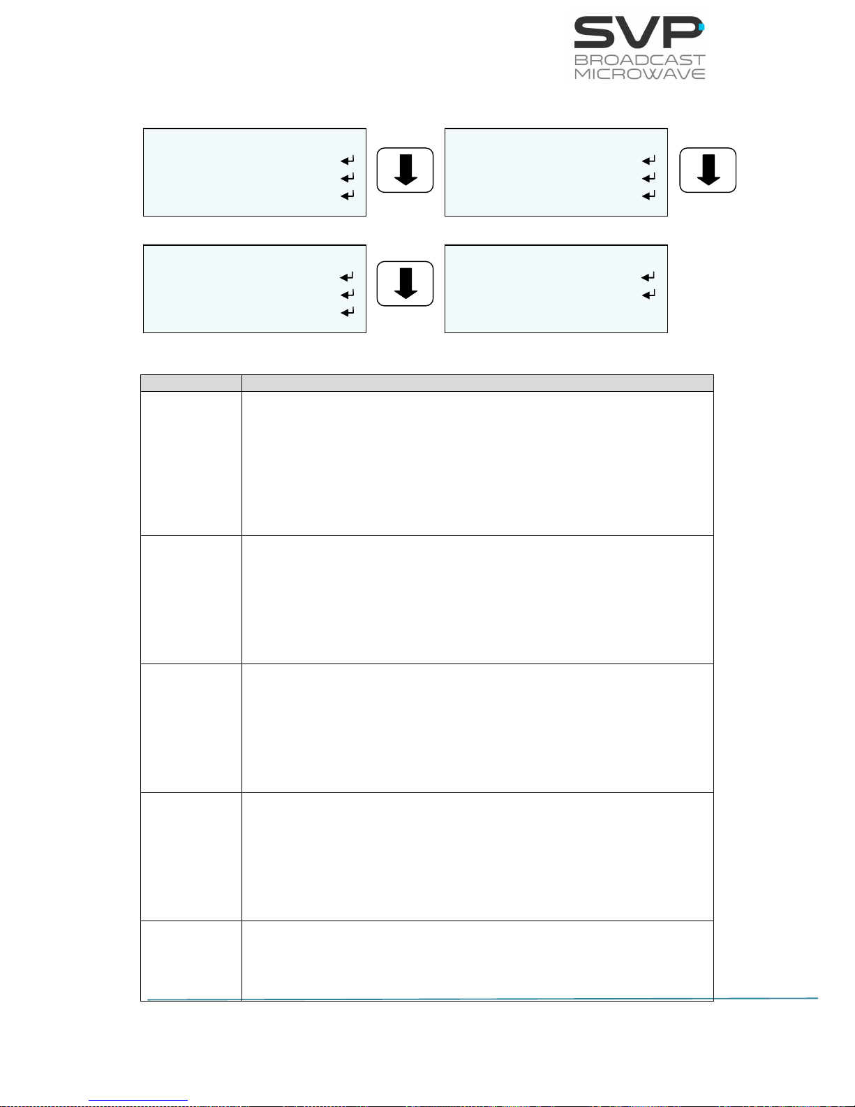
3.5.2.1.17 TS Parameters
Figure 3.34 Encoder TS Menu
Line nº
Function
1
Service Name:
Here the Service name must be entered. So as to change its value
first, press the OK button and then, with the UP, Down arrows select
the desired letter. With the Right, Left keys, the user can select the
character of the word. Press the OK button so as to save the
introduced value. (editable parameter)
2
Program Nº:
Here the program number must be entered. So as to change its
value first, press the OK button and then, with the UP, Down arrows
select the desired number. Press the OK button so as to save the
introduced value. (editable parameter)
3
Video PID:
Here the video packet identifier must be entered. So as to change its
value first, press the OK button and then, with the UP, Down arrows
select the desired number. Press the OK button so as to save the
introduced value. (editable parameter)
4
Audio1 PID:
Here the audio1 packet identifier must be entered. So as to change
its value first, press the OK button and then, with the UP, Down
arrows select the desired number. Press the OK button so as to save
the introduced value. (editable parameter)
5
Audio2 PID:
Here the audio2 packet identifier must be entered. So as to change
its value first, press the OK button and then, with the UP, Down
ENCODER TS
Service Name
Program Nº: 1
Video PID: 273
ENCODER TS
Audio1 PID: 512
Audio2 PID: 513
Data PID: 2100
ENCODER TS
PMT PID: 291
PCR PID: 256
TS id: 7
ENCODER TS
Network id: 7
Network Name
Page 65

58
HENM-70 Encoder & DVB-S2/S Modulator
USER’S MANUAL V5.6
arrows select the desired number. Press the OK button so as to save
the introduced value. (editable parameter)
6
Data PID:
Here the data packet identifier must be entered. So as to change its
value first, press the OK button and then, with the UP, Down arrows
select the desired number. Press the OK button so as to save the
introduced value. (editable parameter)
7
PMT PID:
Here the program map tables packet identifier must be entered. So
as to change its value first, press the OK button and then, with the
UP, Down arrows select the desired number. Press the OK button so
as to save the introduced value. (editable parameter)
8
PCR PID:
Here the program clock reference packet identifier must be entered.
So as to change its value first, press the OK button and then, with
the UP, Down arrows select the desired number. Press the OK
button so as to save the introduced value. (editable parameter)
9
TS id:
Here the Transport Stream identifier must be entered. So as to
change its value first, press the OK button and then, with the UP,
Down arrows select the desired number. Press the OK button so as
to save the introduced value. (editable parameter)
10
Network id:
Here the Network identifier must be entered. So as to change its
value first, press the OK button and then, with the UP, Down arrows
select the desired number. Press the OK button so as to save the
introduced value. (editable parameter)
11
Network Name:
Here the Network name must be entered. So as to change its value
first, press the OK button and then, with the UP, Down arrows select
the desired letter. With the Right, Left keys, the user can select the
character of the word. Press the OK button so as to save the
introduced value. (editable parameter)
Table 3.21 Encoder TS menu options
Page 66

59
HENM-70 Encoder & DVB-S2/S Modulator
USER’S MANUAL V5.6
3.5.2.2 CA-BISS Menu
By using the Up, Down arrow keys, select the CA-BISS option and press
the OK key.
Figure 3.35 CA-BISS Menu
Line nº
Function
1
Mode:
So as to choose the desired encryption, press the Right, Left keys.
(eligible parameter)
The available options are:
None
BISS-1 (Uses an unencrypted key for the BISS key)
BISS-E (Uses an encrypted key)
2
SW:
In this field, the SW password must be introduced, which is valid for
BISS-1 and BISS-E encryption. (editable parameter)
3
User:
In this field, the User password must be introduced, which is valid
only for BISS-E encryption. (editable parameter)
Table 3.22 CA-BISS menu option
CONDITIONAL ACCESS
Mode: BISS-E <
SW: *****************
User: ****************
Page 67

60
HENM-70 Encoder & DVB-S2/S Modulator
USER’S MANUAL V5.6
So as to introduce the key in the BISS-1 option, follow these steps:
1. Choose the BISS-1 option in the Mode field.
2. Go one field down (SW) and press the OK button so as to be allowed
to introduce the key.
3. With Left and Right buttons select one field and with UP, Down
buttons choose one value from 0 to 9 or A to F.
4. Press the OK button to set the key.
So as to introduce the key in the BISS-E option, follow these steps:
1. Choose the BISS-E option in the Mode field.
2. Go one field down (SW) and press the OK button so as to be allowed
to introduce the key.
3. With Left and Right buttons select one field and with UP, Down
buttons choose one value from 0 to 9 or A to F.
4. Press the OK button to set the key.
5. Go another field down (User) and press OK button so as to be allowed
to introduce the User.
6. With Left, Right buttons select one field and with UP and Down
buttons choose one value from 0 to 9 or A to F.
7. Press the OK button to set the User.
The BISS encryption is activated in the modulator and in the ASI output.
3.5.2.3 Modulator Menu
By using the Up, Down arrow keys, select the Modulator option and press
the OK key.
Figure 3.36 Modulator Menu
MODULATOR
DVB-S2
>DVB-S
Page 68
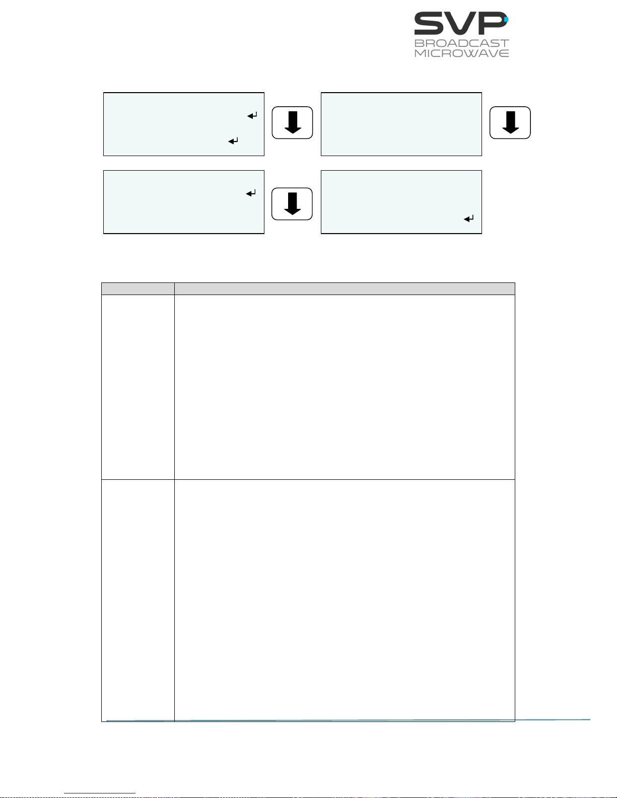
61
HENM-70 Encoder & DVB-S2/S Modulator
USER’S MANUAL V5.6
3.5.2.3.1 DVB-S2
Figure 3.37 DVB-S2 Menu
Line nº
Function
1
Freq:
Select the frequency at which the signal is going to be transmitted.
There are two options available:
Manual
So as to establish the frequency value first, press the OK button and
then, with the Up and Down arrows buttons select the desired value.
So as to save the introduced value, press the OK button. (editable
parameter)
70 MHz
2
Sort of output:
So as to select the sort of output, press Right and Left keys. Once
the option is selected, press the OK button so as to save it. (eligible
parameter)
The possibilities are:
Off (Turn off the RF output)
Low Carrier (The output signal is a continuous wave and the
output power is adjusted to 10 dB less than what is configured in
the power field)
Carrier (The RF output is carrier only (CW) without modulation.
So as specify the output power, select it in the power option)
Modulator (The RF output carrier with modulation. So as specify
the output power, select it in the field below)
DVB-S2
F: 1.640, 365MHz >
Low Carrier <>
L-BAND: -5.5 dBm
>
DVB-S2
BUC LO: 13,05 GHz <
Modul: 32APSK <
LDPC Fec: 9/10 <
DVB-S2
SR: 12.4MS/s B:14
Roll Off: 0,20 >
Pilots: On >
DVB-S2
Spectrum: Normal >
10 MHz: Off <
Antenna Gain: 42dBi
Page 69

62
HENM-70 Encoder & DVB-S2/S Modulator
USER’S MANUAL V5.6
3
Power:
In this field, the value of the output power can be selected. The
possible output power range is from -20 to 5 dBm. (editable
parameter)
L-BAND (The output power of the HENM-70 in dBm)
HPA (The output power of the amplifier in dBW)
EIRP (HPA + Antenna Gain)(dBW)
4
BUC LO:
BUC LO is used in the transmission (uplink) of satellite signals. It
converts a band of frequencies from a lower frequency to a higher
frequency. In this option, the user can choose the local oscillator of
the BUC.(elegible parameter)
The available options are:
None
12,80 GHz
13,05 GHz
5
Modul:
Here the constellation of the modulation can be chosen. Use Right
and Left buttons so as to select the desired constellation. (eligible
parameter)
The available options are:
QPSK
8PSK
16APSK
32APSK
6
LDPC Fec:
Here the value of the Forward Error Correction can be chosen. Use
Right and Left buttons so as to select the desired value. (eligible
parameter)
The available options are:
1/4
1/3
2/5
1/2
3/5
2/3
3/4
4/5
Page 70

63
HENM-70 Encoder & DVB-S2/S Modulator
USER’S MANUAL V5.6
5/6
8/9
9/10
7
SR:
In this field, the value of the symbol rate can be introduced.
(editable parameter)
BW:
In this field it is displayed the value of the bandwidth of the
transmitted signal. (reading parameter)
8
Roll Off:
Here the value of Roll Off factor can be chosen. Use Right and Left
buttons so as to select the desired value. (eligible parameter)
The available options are:
0.20
0.25
0.35
9
Pilots:
In this field, selecting the ON option carrier pilots are transmitted. If
OFF option is selected, then no carrier pilots are transmitted. So as
to select an option, Right, Left keys must be pressed. (eligible
parameter)
The available options are:
On
Off
10
Spectrum:
Here the type of the spectrum is configured. Inverted spectrum is
just another method to help preventing signal theft. Use Right and
Left buttons so as to select the desired option. (eligible parameter)
The available options are:
Normal
Invert
Page 71
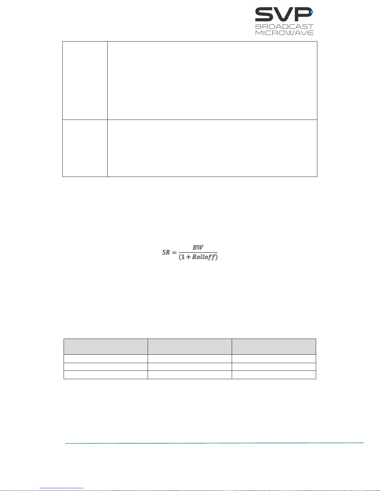
64
HENM-70 Encoder & DVB-S2/S Modulator
USER’S MANUAL V5.6
11
10 MHz:
This feature provides a reference signal of 10MHz to the satellite upconverter in case of being ON. (eligible parameter)
The available options are:
On
Off
12
Antenna Gain (dBi):
Select the gain of the transmitter antenna. Press the OK button to
configure it and then the OK button again to save the introduced
value.(editable parameter)
Table 3.23 DVB-S2 menu options
3.5.2.3.2 Symbol Rate calculation
So as to calculate the symbol rate needed for a determined bandwidth, the
next equation must be implemented:
Where:
SR: Symbol Rate in Msymb/s
BW: Bandwidth in MHz
Next, it is shown a table as an example of the Symbol Rate values for a
determined Bandwidth of 28 MHz.
Bandwidth (MHz)
Roll-off
Symbol Rate
(Msymb/s)
28
0.20
23.33
28
0.25
22.4
28
0.35
20.74
Table 3.24 Symbol Rate calculation
Page 72
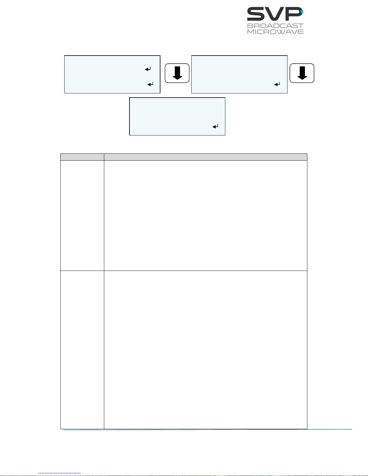
65
HENM-70 Encoder & DVB-S2/S Modulator
USER’S MANUAL V5.6
3.5.2.3.3 DVB-S
Figure 3.38 DVB-S Menu
Line nº
Function
1
Freq:
Select the frequency at which the signal is going to be transmitted.
There are two options available:
Manual
So as to establish the frequency value first, press the OK button and
then, with the Up and Down arrows buttons select the desired value.
So as to save the introduced value, press the OK button. (editable
parameter)
70 MHz
2
Sort of output:
So as to select the sort of output, press Right and Left keys. Once
the option is selected, press the OK button so as to save it. (eligible
parameter)
The possibilities are:
Off (Turn off the RF output)
Low Carrier (the output signal is a continuous wave and the
output power is adjusted to 10 dB less than what is configured in
the power field)
Carrier (The RF output is carrier only (CW) without modulation.
So as specify the output power, select it in the power option)
Modulator (The RF output carrier with modulation. So as specify
the output power, select it in the field below)
DVB-S
F: 1.360,500MHz
Modulation <>
L-BAND: -5.5 dBm
DVB-S
BUC LO: None >
FEC: 7/8 <
SR: 12.4MS/s B:14
DVB-S
Spectrum: Normal >
10 MHz: On >
Antenna Gain: 42 dBi
Page 73

66
HENM-70 Encoder & DVB-S2/S Modulator
USER’S MANUAL V5.6
3
Power:
In this field, the value of the output power can be selected. The
possible output power range is from -20 to 5 dBm. (editable
parameter)
The available options are:
L-BAND (The output power of the HENM-70 in dBm)
HPA (The output power of the amplifier in dBW)
EIRP (HPA + Antenna Gain)
4
BUC LO:
BUC LO is used in the transmission (uplink) of satellite signals. It
converts a band of frequencies from a lower frequency to a higher
frequency. In this option, the user can choose the local oscillator of
the BUC.(elegible parameter)
The available options are:
None
12,80 GHz
13,05 GHz
5
Fec:
Here the value of the Forward Error Correction can be chosen. Use
Right and Left buttons so as to select the desired value. (eligible
parameter)
The available options are:
1/2
2/3
3/4
5/6
7/8
6
SR:
In this field, the value of the symbol rate can be introduced.
(editable parameter)
BW:
In this field the value of the bandwidth of the transmitted signal is
displayed. (reading parameter)
Page 74

67
HENM-70 Encoder & DVB-S2/S Modulator
USER’S MANUAL V5.6
7
Spectrum:
Here the type of the spectrum is configured. Inverted spectrum is
just another method to help preventing signal theft. Use Right and
Left buttons so as to select the desired option. (eligible parameter)
The available options are:
Normal
Invert
8
10 MHz:
This feature provides a reference signal of 10MHz to the satellite upconverter in case of being ON. (eligible parameter)
The available options are:
ON
OFF
9
Antenna Gain (dBi):
Select the gain of the transmitter antenna. Press the OK button to
configure it and then the OK button again to save the introduced
value.(editable parameter)
Table 3.25 DVB-S menu options
Page 75
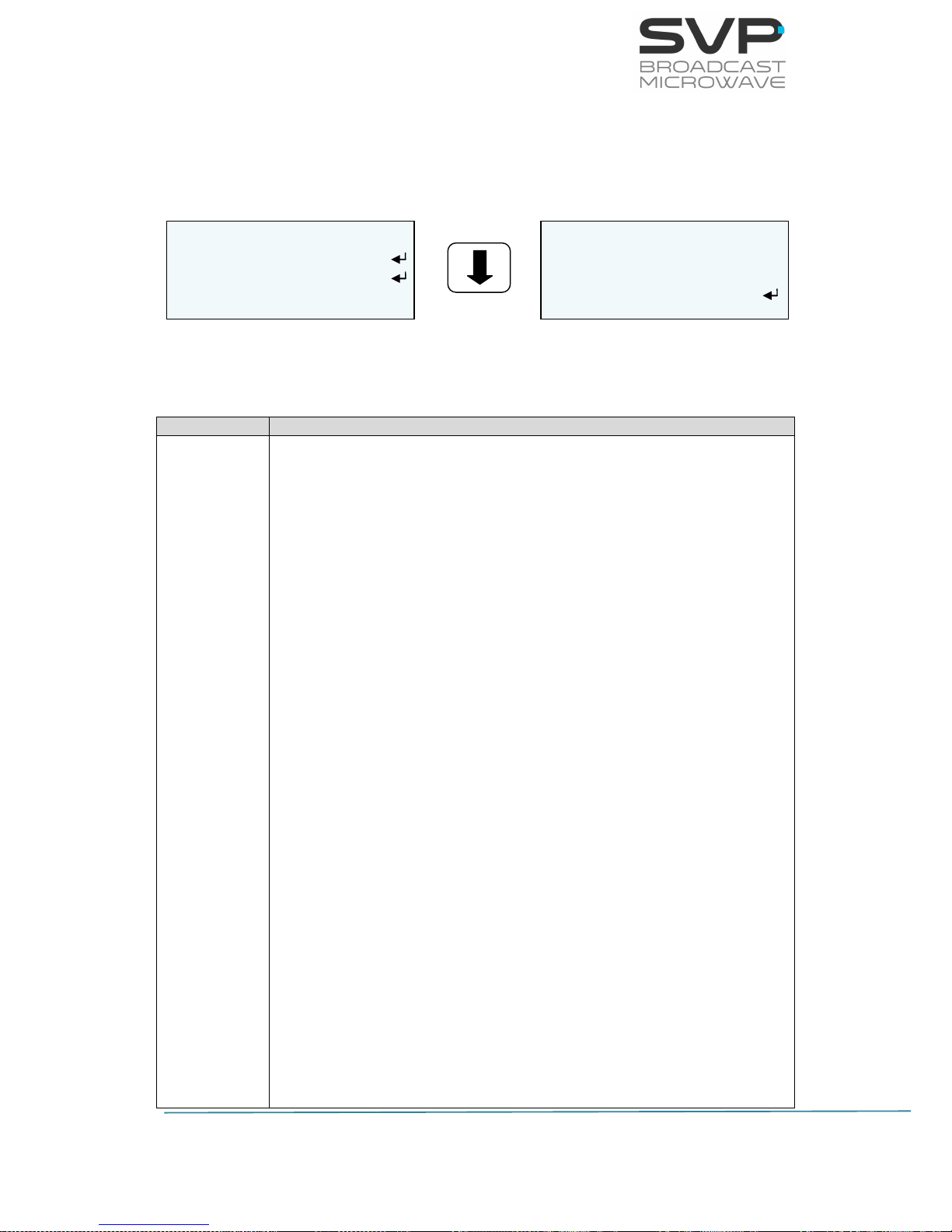
68
HENM-70 Encoder & DVB-S2/S Modulator
USER’S MANUAL V5.6
3.5.2.4 IP Out
By using the Up, Down arrow keys, select the IP Out option and press the
OK key.
Figure 3.39 Unit Menu
Line nº
Function
1
Local IP:
In this option it can be set the IP address, Mask, Gateway and MAC
of the device in case it is wanted to control the device remotely. So
as to change those parameters, press OK button and then, with the
Up and Down keys select the desired option.
- LOC:
IP address of the device which is going to send the
information. So as to change the IP address first press OK
button and then, with the Up, Down keys select the desired
number. So as to change from one character to another,
press Right, Left keys. So as to save the value, press the OK
button. (editable parameter)
- MSK:
Subnet address of the device which is going to send the
information. So as to change the Subnet Mask address first
press OK button and then, with the Up, Down keys select the
desired number. So as to change from one character to
another, press Right, Left keys. So as to save the value,
press the OK button. (editable parameter)
- GAT:
Gateway address of the device which is going to send the
information. So as to change the Gateway address first press
OK button and then, with the Up, Down keys select the
desired number. So as to change from one character to
another, press Right, Left keys. So as to save the value,
press the OK button. (editable parameter)
- MAC ADDRESS
The MAC Address of the transmitter is shown. (reading
parameter)
IP Out
Local IP
DestinationIP&Port
Fec: Disable >
IP Out
TP per IP: 7 (1..7) <
Protocol: UDP >
TTL: 80 (1...255)
Page 76

69
HENM-70 Encoder & DVB-S2/S Modulator
USER’S MANUAL V5.6
2
Destination IP & Port:
In this option, the IP address and the port number of the device to
which data is sent must be configured. In case it is wanted to send
data to a multicast address just enter the desired multicast address.
So as to change the IP address and the port number, first press OK
button and then, with the Up, Down keys select the desired number.
So as to change from one character to another, press Right, Left
keys. So as to save the value, press OK button. (editable
parameter)
3
FEC:
In this field, the Forward Error Correction can be enabled or
disabled. In case it is enabled, the number of columns and rows can
be configured pushing firstly the OK button and then, with the Up,
Down arrows, the number of columns and rows wanted can be
selected. If FEC option is enabled then, the only protocol which can
be used is RTP. (eligible parameter)
4
TP per IP:
In this field, the number of Transport Stream packets per IP (from 1
to 7) can be configured. So as to select the desired value, press the
Right, Left buttons. (eligible parameter)
5
Protocol:
The type of protocol used for the communication can be RTP or UDP.
So as to select the desired protocol for the communication, use
Right, Left buttons. (eligible parameter)
6
TTL:
This field limits the lifetime of data. The Time to Live value (from 1
to 255) means the number of routers that a packet can reach until
that packet is discarded. So as to configure this value, first press the
OK button and then, with the Up, Down, and Right, Left buttons
select the desired value. So as to save the value, press OK button.
(editable parameter)
Table 3.26 IP Out menu options
Page 77
70
HENM-70 Encoder & DVB-S2/S Modulator
USER’S MANUAL V5.6
3.5.2.5 Unit Menu
By using the Up, Down arrow keys, select the Unit option and press OK
key.
Figure 3.40 Unit Menu
3.5.2.5.1 Alarms
In this option, different alarms which are present in the device are shown.
The alarm screen can be accessed by pressing the OK button from the main
screen as well. So as to return to the main screen from the alarm screen,
cross button must be pressed.
The different alarms that can appear in the device are:
Voltage High.
Voltage Low.
Temperature High.
ASI Overflow: this alarm means that the input bitrate is higher than
the one that can be modulated due to the parameters configured
(constellation, FEC, GI...).
The different warnings that can appear in the device are:
No Video Input.
No GPS.
UNIT
Alarms (02)
Monitor
Webserver & SNMP
UNIT
Miscellaneous
Firmware
BUC S/S2 Unit
Page 78

71
HENM-70 Encoder & DVB-S2/S Modulator
USER’S MANUAL V5.6
3.5.2.5.2 Monitor
Figure 3.41 Monitor Menu
Temperature:
In this field, the internal temperature of the device is displayed. With
the Right, Left keys, the user can select if the temperature is shown
in ºC or in ºF. Also, the value which is between square brackets
means the speed of the fans (values from 0 to 3) where 0 means that
the fans are stopped and value 3 is the maximum speed. (reading
parameter)
Voltage:
In this field, the voltage of the device is shown. (reading parameter)
UNIT MONITOR
Self Check: OK
Temp: +37,1ºC (0) >
Voltage: +11.6V
Page 79
72
HENM-70 Encoder & DVB-S2/S Modulator
USER’S MANUAL V5.6
3.5.2.5.3 Webserver & SNMP
Figure 3.42 Webserver & SNMP Menu
Line nº
Function
1
Local IP:
In this option it can be set the IP address of the device in case it is
wanted to control the device remotely. So as to change the IP
address first press OK button and then, with the Up and Down keys
select the desired number. So as to change from one character to
another, press Right and Left keys. Press the OK button so as to
save the introduced value. (editable parameter)
2
Subnet Mask:
Here it can be written the Subnet Mask address of the device. So as
to change the Subnet Mask address first press OK button and then,
with the Up and Down keys select the desired number. So as to
change from one character to another, press Right and Left keys.
Press the OK button so as to save the introduced value. (editable
parameter)
3
Gateway:
In this option, the address of the Gateway must be written. So as to
change the Gateway address first press the OK button and then,
with the Up and Down keys select the desired number. So as to
change from one character to another, press Right and Left keys.
Press the OK button so as to save the introduced value. (editable
parameter)
4
MAC ADDRESS (Reading parameter)
In this field, the MAC address of the device is shown.
UNIT ETHERNET
LOC 192.168.001.010
MSK 255.255.000.000
GAT 192.168.001.001
UNIT ETHERNET
70-B3-D5-1A-C0-00
Admin Pass: ********
Restore Admin Pas
UNIT ETHERNET
User Pass: ********
Restores User Pas
Page 80

73
HENM-70 Encoder & DVB-S2/S Modulator
USER’S MANUAL V5.6
5
Admin Pass:
The administrator’s password is introduced. It can be set an own
password which is a list of 8 digits.
To set the password, press the OK button and the use the Up and
Down button to establish the desired value, the press Right and Left
buttons to change other digits. Finally press OK button to save the
introduced values.
6
Restore Admin Pass:
This option enables to restore the default administrator password
(00000000).
7
User Pass:
The user’s password is introduced. It can be set an own password
which is a list of 8 digits.
To set the password, press the OK button and the use the Up and
Down button to establish the desired value, the press Right and Left
buttons to change other digits. Finally press OK button to save the
introduced values.
8
Restore User Pass:
This option enables to restore the default user password
(00000000).
Table 3.27 Webserver & SNMP menu options
Page 81

74
HENM-70 Encoder & DVB-S2/S Modulator
USER’S MANUAL V5.6
3.5.2.5.4 Miscellaneous
Figure 3.43 Miscellaneous Menu
Line nº
Function
1
Keyboard Beep:
If the option On is selected then, each time a key is pressed a beep
sound will appear. If option Off is selected then, there will be no
sound when a key is pressed. (eligible parameter)
The available options are:
On
Off
2
Keyboard Lock:
If the On option is selected and then, the buttons of the equipment
remain for 5 minutes without being pressed, a message will appear
in the screen saying that the keyboard is locked. Pressing the cross
button, the keyboard can be unlocked. If the Off option is selected
there will be no messages in the screen.
The available options are:
On
Off
3
Night Mode:
There are four possible states for the night mode. If night mode is in
state 0 then the light in the screen will shine more than if it is in
state 1. If the state is three then, the light in the screen will be the
lowest of the four possible states. (eligible parameter)
The available options are:
0
1
2
3
UNIT MISCELLANEOUS
Keyboard Beep: Off <
Keyboard Lock: Off <
Night Mode: 0 >
UNIT MISCELLANEOUS
Dist Units: Km >
S/N: 660010911
70-B3-D5-1A-C0-00
Page 82

75
HENM-70 Encoder & DVB-S2/S Modulator
USER’S MANUAL V5.6
4
Dist Units:
If miles is selected then, all the distances will be in miles and the
same occurs if kilometers is selected. (eligible parameter)
The available options are:
Kilometers
Miles
5
S/N:
In this field the serial number of the device is shown (reading
parameter).
6
MAC Address:
The MAC Address of the transmitter is shown. (reading parameter)
Table 3.28 Miscellaneous menu options
Page 83
76
HENM-70 Encoder & DVB-S2/S Modulator
USER’S MANUAL V5.6
3.5.2.5.5 Firmware
Figure 3.44 Firmware Menu
Line nº
Function
1
Update Firmware:
This field is the one for updating the version of the device. So as to
update the equipment properly, follow the instructions below.
2
Restore Default:
In this option, the equipment is restored to the first factory version.
So as to restore the equipment to the initial set up, press the OK
button.
3
Rev:
In this field it is shown the number of the version installed in the
device. The characters which describe the number of the version are
the one inside the red box shown in the figure above. The rest of the
characters are important for the manufacturer but are not important
for the user.
Table 3.29 Firmware menu options
Update Firmware
Restore Default
Rv:v5.3501351916-18
Number of the version of the device
Page 84
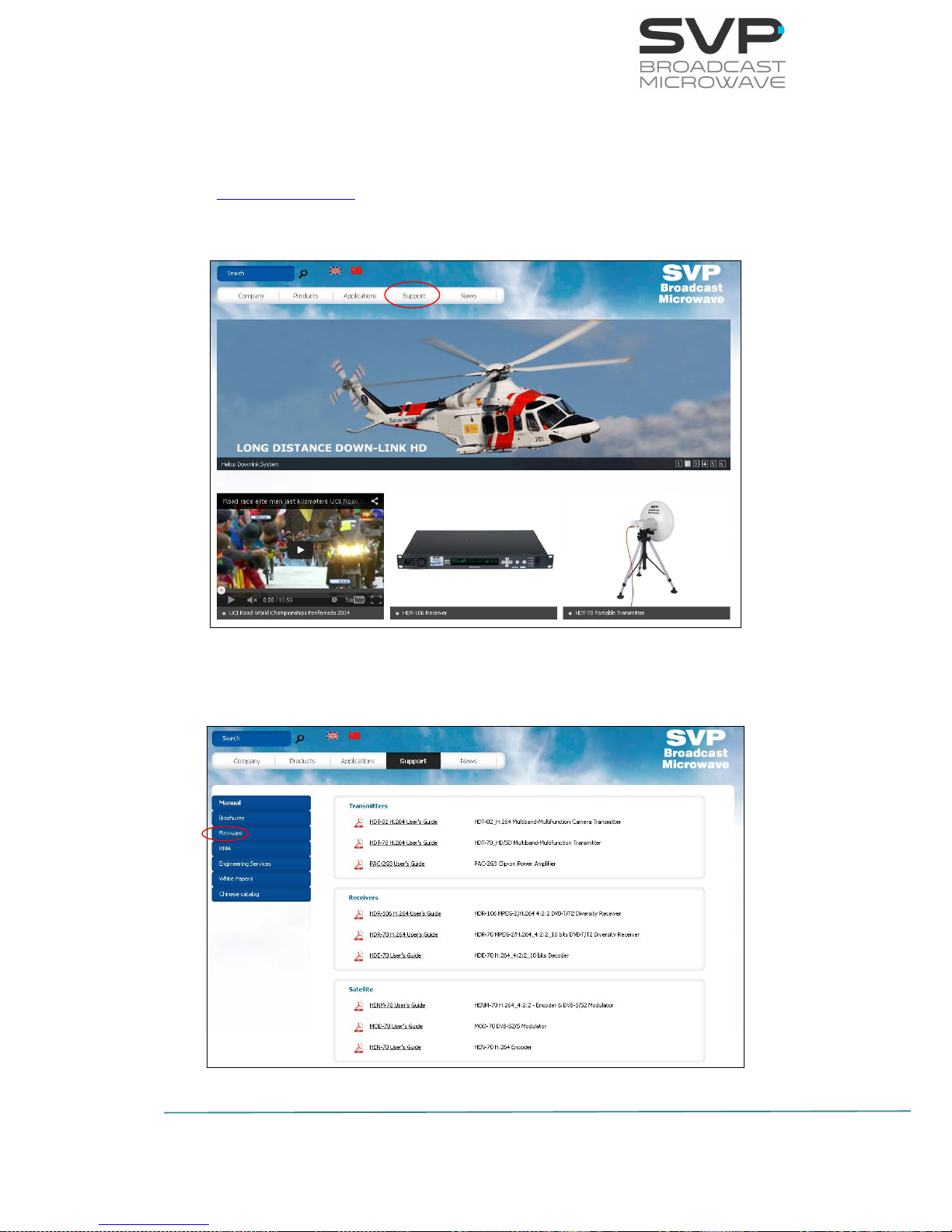
77
HENM-70 Encoder & DVB-S2/S Modulator
USER’S MANUAL V5.6
Next, the necessary steps so as to make a successful update are explained.
1) The latest firmware is allocated in the webpage of SVP Broadcast
Microwave. So as to access to the firmware file, first enter
www.svpbm.com in your web browser.
2) Click on the Support tab.
Figure 3.45 Updating firmware step 2
3) Click on Firmware.
Figure 3.46 Updating firmware step 3
Page 85
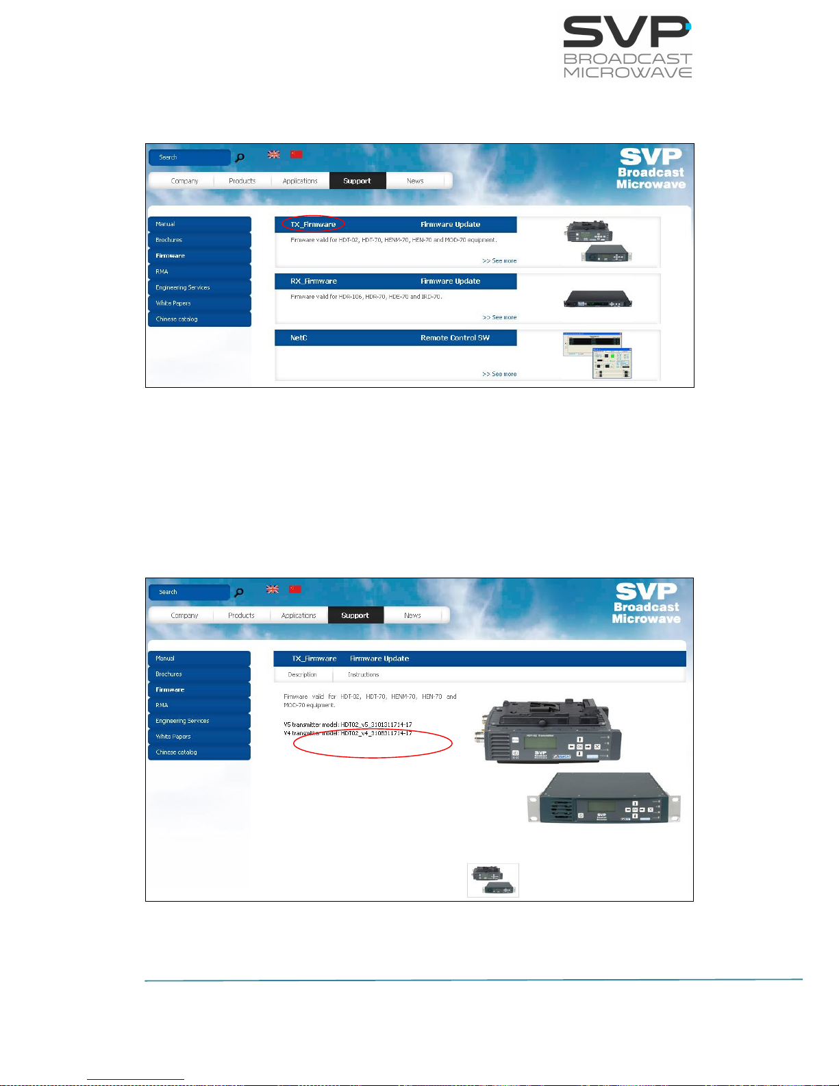
78
HENM-70 Encoder & DVB-S2/S Modulator
USER’S MANUAL V5.6
4) Go to TX_Firmware.
Figure 3.47 Updating firmware step 4
5) Select the firmware version to download the file.
To verify the version of the device, go to firmware field and then look
at the Rv option to check the number of the version installed in the
device (the first two digits).
Figure 3.48 Updating firmware step 5
Page 86
79
HENM-70 Encoder & DVB-S2/S Modulator
USER’S MANUAL V5.6
6) Once the firmware file has been downloaded, save it in a USB device.
In the USB device, the only file that can be allocated inside it is the
firmware file of the device to be updated.
7) With the equipment completely power off (with no power
supply), insert the USB device in the USB connector, situated in the
rear panel.
Before introducing the USB device, remove the power supply of the
equipment.
8) Now, switch on the device.
9) Go to Unit menu. In case of being in the main screen, press cross
button so as to access to the menu. There, with the Up, Down
buttons, select the Unit option.
10) Select Firmware by pressing the OK button.
11) Select Check USB Memory with the OK button.
12) Now, automatically the device updates the firmware. The screens
which are shown below display the different steps that the device is
making while the updating process.
Don’t power off the device during the updating process.
Page 87

80
HENM-70 Encoder & DVB-S2/S Modulator
USER’S MANUAL V5.6
3.5.2.5.6 BUC S/S2 Unit
Figure 3.49 BUC S/S2 Unit Menu
When a BUC is connected to the device, the followings options of the BUC
will be available.
Line nº
Function
1
Alarms:
The alarms of the connected BUC are shown.
2
Temperature:
In this option, the temperature of the BUC is shown in the screen.
3
Type:
In this option, the type and the model of the BUC is shown in the
screen.
The available options are:
IRT
WAVE
Table 3.30 BUC S/S2 Unit menu options
Alarms (None)
Temp: +40.8 ºC
Typ: IRT (KXB0470) >
Page 88
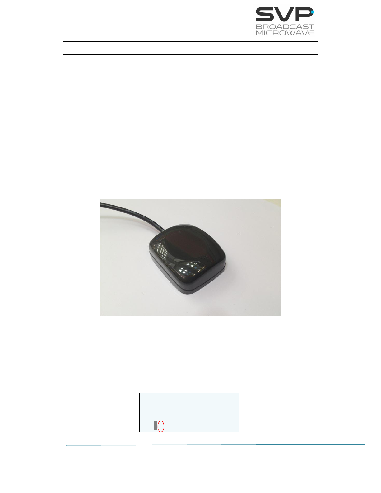
81
HENM-70 Encoder & DVB-S2/S Modulator
USER’S MANUAL V5.6
F: 14000,000MHz DVBS2
P: +2dBm SR22.4 B28
16APSK 4/5 69.200
HAUG -------- 420S
Chapter 4: GPS Application
4.1 Introduction
The HENM-70 encoder and modulator has a GPS antenna input in order to
give information to the device about the positioning data. The connexion of
the GPS antenna to this input, allows the transference of the information
given.
Once the information is kept inside the device, it can be sent to the HDE-70
decoder or to the HDR-70 receiver. If the signal arrives correctly to the
receiver system, then the IRD-70 will have all the GPS data available and
this receiver device will be able to calculate the direction, distance,
positioning... of the transmitter.
The IRD-70 also includes another feature that consists on an output RS232
connection which allows watching throughout Google Maps application the
position of the transmitter in real time.
Figure 4.1 GPS antenna
4.2 Main Screen
Next it is explained the value of the data field which appears in the main
screen of the HENM-70 encoder & modulator.
Figure 4.2 Main screen
Page 89
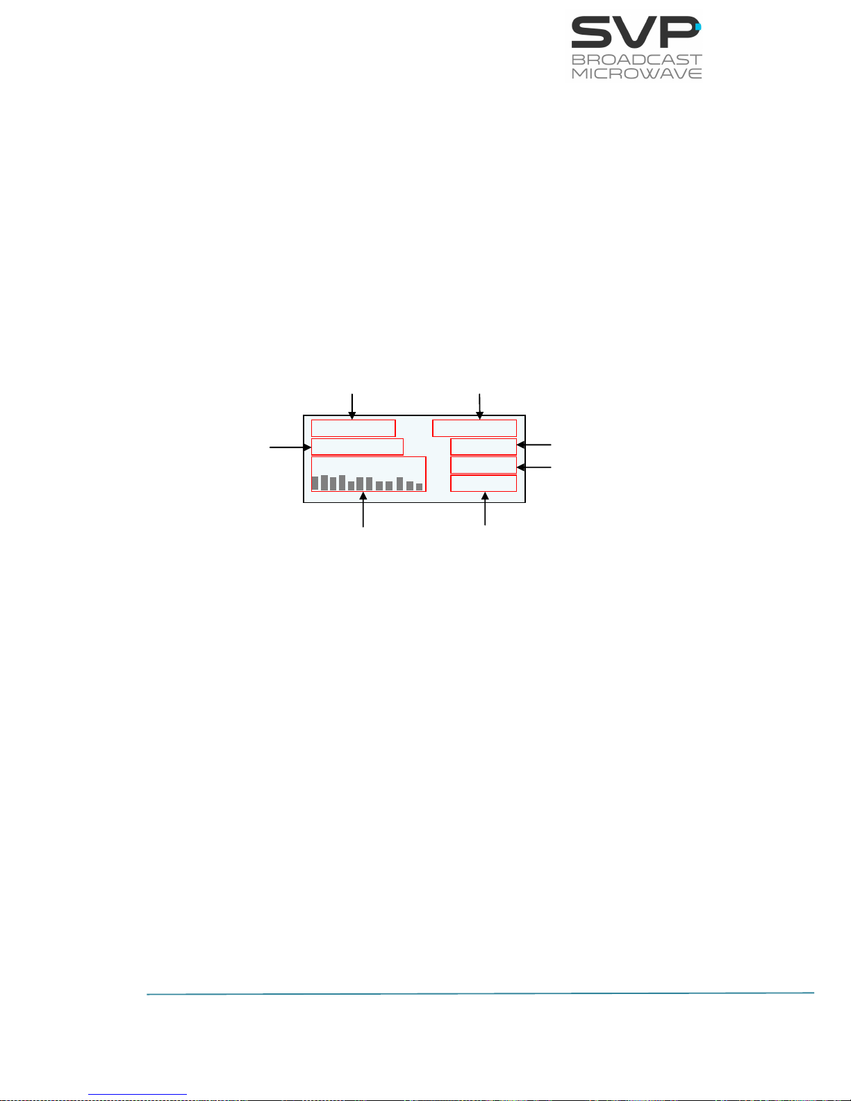
82
HENM-70 Encoder & DVB-S2/S Modulator
USER’S MANUAL V5.6
The data status field indicates with a darkened X that it is disabled. When
this parameter is enabled and blinkers, this means that there is nothing
connected to the data input. When this field alternates the value between
‘g’ and ‘G’, it means that it is trying to get the GPS satellites. If the ‘G’ does
not vary, then it is connected to the satellites.
4.3 GPS transmitter screen
So as to access to the GPS screen, go to the encoder option in the menu.
Once inside this option, go to the Data field and choose GPS. Press the OK
button and then the GPS screen appears.
Next the different fields meanings are shown:
Figure 4.3 GPS transmitter screen
Longitude of the HENM-70: It specifies the longitude position of the
device.
Speed of the HENM-70: It shows the speed of the device in knot.
Direction of the HENM-70: The direction of the device is shown in this
field.
Latitude of the HENM-70: It specifies the latitude position of the
device.
Height of the HENM-70: The height of the device from ground is
specified in this value.
Satellite Level: The level of each satellite signal received is shown in
this field.
Date: The updated date is shown.
#--º--.---´ ---k ---º
#---º--.---´ -----mt
Satellite Level --/--/--
--:--:--
Level of the satellite signals
Time
Date
Height (meters)
Speed(knot)/
Direction(degrees)
Longitude of the
HENM-70
Latitude of the
HENM-70
Page 90
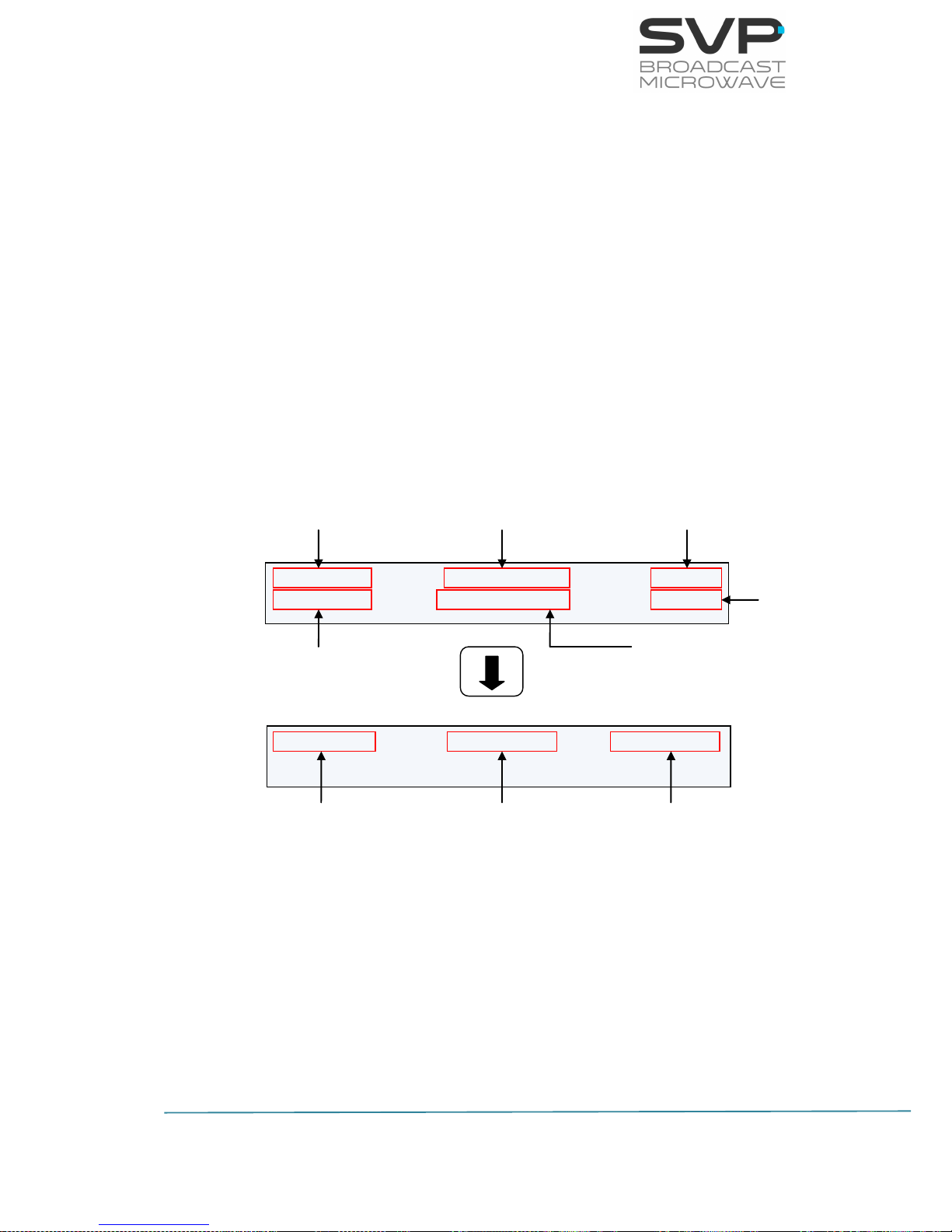
83
HENM-70 Encoder & DVB-S2/S Modulator
USER’S MANUAL V5.6
4.4 GPS IRD-70 decoder screen
So as to access to the GPS screen, go to the decoder option in the menu.
Once inside this option, go to the Decoder.Data field and choose GPS. Press
the OK button and then the GPS screen appears.
The format of the GPS coordinates used is decimal minutes as shown in the
next example:
N43º02.032’
W023º03.023’
Next there are shown the different fields meanings.
Figure 4.4 GPS receiver screen
#---º--.---´ ---k---º-----mt --/--/-#---º--.---´ S-- ----km ---º --:--:--
Rec Coords: #---º--.---´ #---º--.---´
Latitude of the
transmitter
Speed(knot)/
Direction(degrees)/
Height (meters) of the
transmitter
Date
Time
Nº of Satellites/
Distance from receiver to transmitter/
Direction from transmitter to
receiver(degrees)
Coordinates of
the receiver
Latitude of
the
receiver
Longitude
of the
receiver
Longitude of the
transmitter
Page 91

84
HENM-70 Encoder & DVB-S2/S Modulator
USER’S MANUAL V5.6
Longitude of the transmitter: It specifies the longitude position of the
transmitter.
Speed of the transmitter: It shows the speed of the transmitter in
knot .
Direction of the transmitter: The direction of the transmitter is shown
in this field.
Height of the transmitter: The height of the transmitter from ground
is specified in this value.
Date: The updated date is shown.
Latitude of the transmitter: It specifies the latitude position of the
transmitter.
Nº of Satellites: The number of satellites connected to the GPS
antenna in the transmitter.
Distance from receiver to transmitter: The existence distance from
receiver to transmitter is displayed in this field.
Direction from transmitter to receiver: The direction of the
transmitter with respect to the receiver.
Coordinates of the receiver: The format of the GPS coordinates used
is decimal minutes, for example, N43º02.032’ and W023º03.023’. So as
to introduce these coordinates, first of all, go to the Rec. Coords field.
Once situated in this field, press the OK button so as to edit the
coordinates. The first coordinate to introduce is the latitude of the
receiver and the second the longitude of the receiver. So as to save the
values introduced, OK button must be pressed.
Longitude of the receiver: In this field the user can enter the
longitude of the receiver.
Latitude of the receiver: In this field the user can enter the latitude of
the receiver.
Page 92

85
HENM-70 Encoder & DVB-S2/S Modulator
USER’S MANUAL V5.6
4.5 Application example
Suppose that it is wanted to know the constant positioning of the
transmitter device. This is achievable with the next items:
- HENM-70 encoder & modulator
- GPS antenna
- IRD-70 Demodulator & Decoder
With the GPS antenna connected to the HENM-70, positioning of the device
is achieved once the GPS system is connected to the necessary satellites.
Data obtained in the transmitter is the positioning of the device.
Next, this GPS data is sent to the IRD-70 decoder.
In the next page, a picture of this system is shown:
Page 93
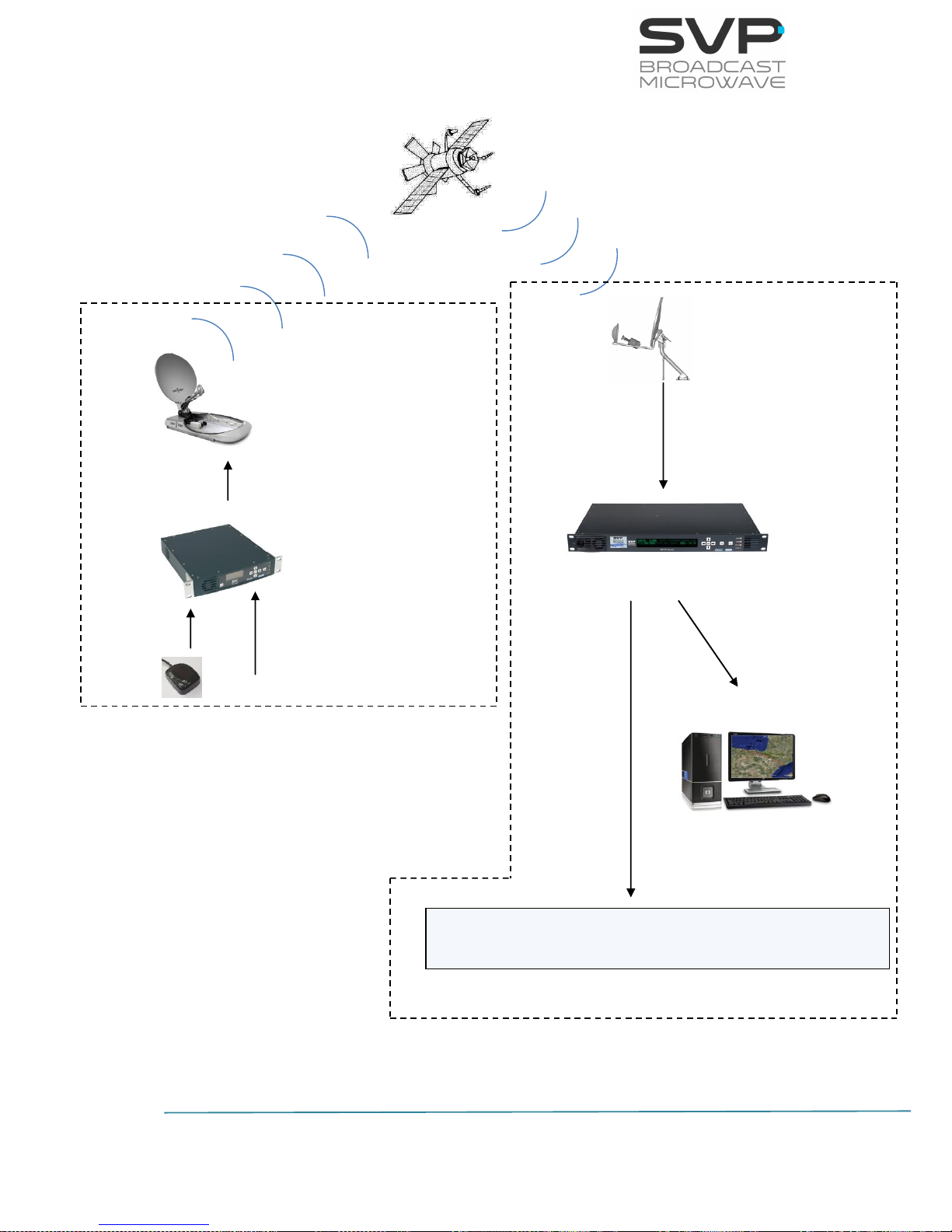
86
HENM-70 Encoder & DVB-S2/S Modulator
USER’S MANUAL V5.6
Figure 4.5 GPS system example picture
HENM-70 encoder &
modulator
with GPS antenna
IRD-70 GPS screen
IRD-70 Demodulator & Decoder
E20º45.512´ 10k47º1mt 04/10/13
N60º73.984´ S3 100km 100º 09:45:34
RS232 connection
PC with Google Earth
Video
GPS
- Power Aplifier
- Up Converter
- Parabolic Antenna
Transmitter System
Receiver System
Page 94
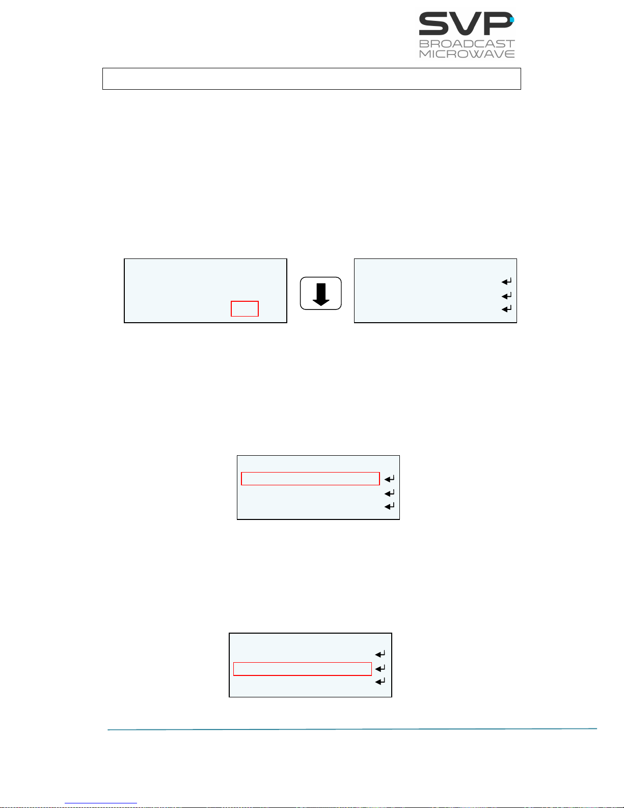
87
HENM-70 Encoder & DVB-S2/S Modulator
USER’S MANUAL V5.6
Chapter 5: Web Server
5.1 Introduction
This equipment can be controlled by the use of a PC connected at the rear
panel Ethernet connector.
To enable the browser interface correctly, the IP address, Subnet Mask,
Gateway, User Password and Administrator Password need to be set
correctly on this unit. Next, the steps so as to setup network parameters
are shown:
1. Go to Unit -> Webserver & SNMP
Figure 5.1 Web Server screen
2. Select the LOC option and set an IP address. So as to change the IP
address first press the OK button and then, with the Up, Down keys
select the desired number. So as to change from one character to
another, press Right, Left keys. Press the OK button so as to save the
introduced value.
Figure 5.2 Local IP
3. Select MSK option and set the Subnet Mask address. So as to change
the Subnet Mask address first press the OK button and then, with the
Up, Down keys select the desired number. So as to change from one
character to another, press Right, Left keys. Press the OK button so
as to save the introduced value.
Figure 5.3 Subnet Mask
UNIT ETHERNET
LOC 192.168.001.010
MSK 255.255.000.000
GAT 192.168.001.001
HENM-70
Encoder Mod&RF
CA-BISS IP.Out
Unit
UNIT ETHERNET
LOC 192.168.001.010
MSK 255.255.000.000
GAT 192.168.001.001
UNIT ETHERNET
LOC 192.168.001.010
MSK 255.255.000.000
GAT 192.168.001.001
Page 95
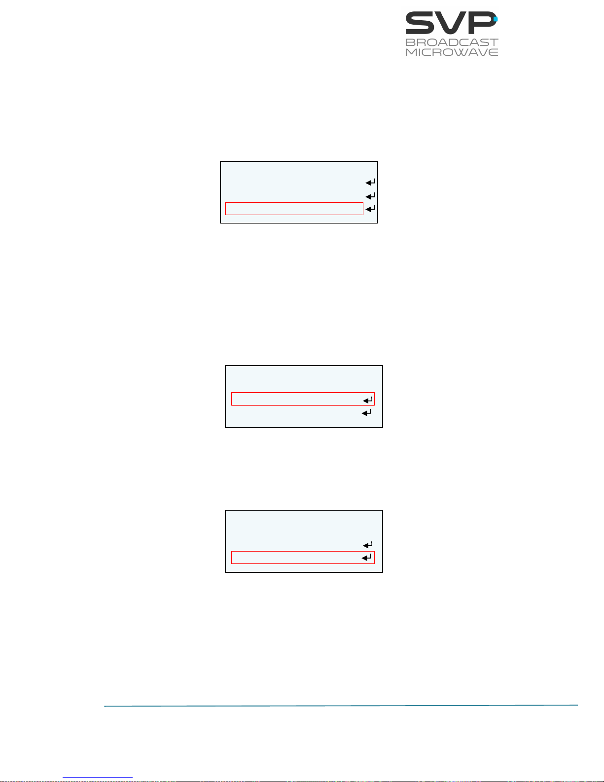
88
HENM-70 Encoder & DVB-S2/S Modulator
USER’S MANUAL V5.6
4. Select GAT option and set the Gateway address. So as to change the
Gateway address first press OK button and then, with the Up, Down
keys select the desired number. So as to change from one character
to another, press Right, Left keys. Press the OK button so as to save
the introduced value.
Figure 5.4 Gateway
5. Select Admin Pass option and set the administrator’s password. If it is
wanted to access to the Webserver directly without setting any
password, the Admin Pass must be set to 0 (00000000). However, if
it is wanted to set an administrator’s password, it is necessary to
introduce 8 digits. In this way, with this password, the administrator
can access to the Webserver and make any configuration,
modification or monitoring.
Figure 5.5 Admin Pass
6. Select Restore Admin Pass option to restore de default value of the
administrator’s password.
Figure 5.6 Restore Admin Pass
7. Select User Pass option and set the user’s password. If it is wanted to
access to the Webserver directly without setting any password, the
User Pass must be set to 0 (00000000). However, if it is wanted to
set a user’s password, it is necessary to introduce 8 digits. In this
way, with this password, the user can access to the Webserver and
make any monitoring.
UNIT ETHERNET
LOC 192.168.001.010
MSK 255.255.000.000
GAT 192.168.001.001
UNIT ETHERNET
70-B3-D5-1A-C0-00
Admin Pass: ********
Restore Admin Pas
UNIT ETHERNET
70-B3-D5-1A-C0-00
Admin Pass: ********
Restore Admin Pas
Page 96
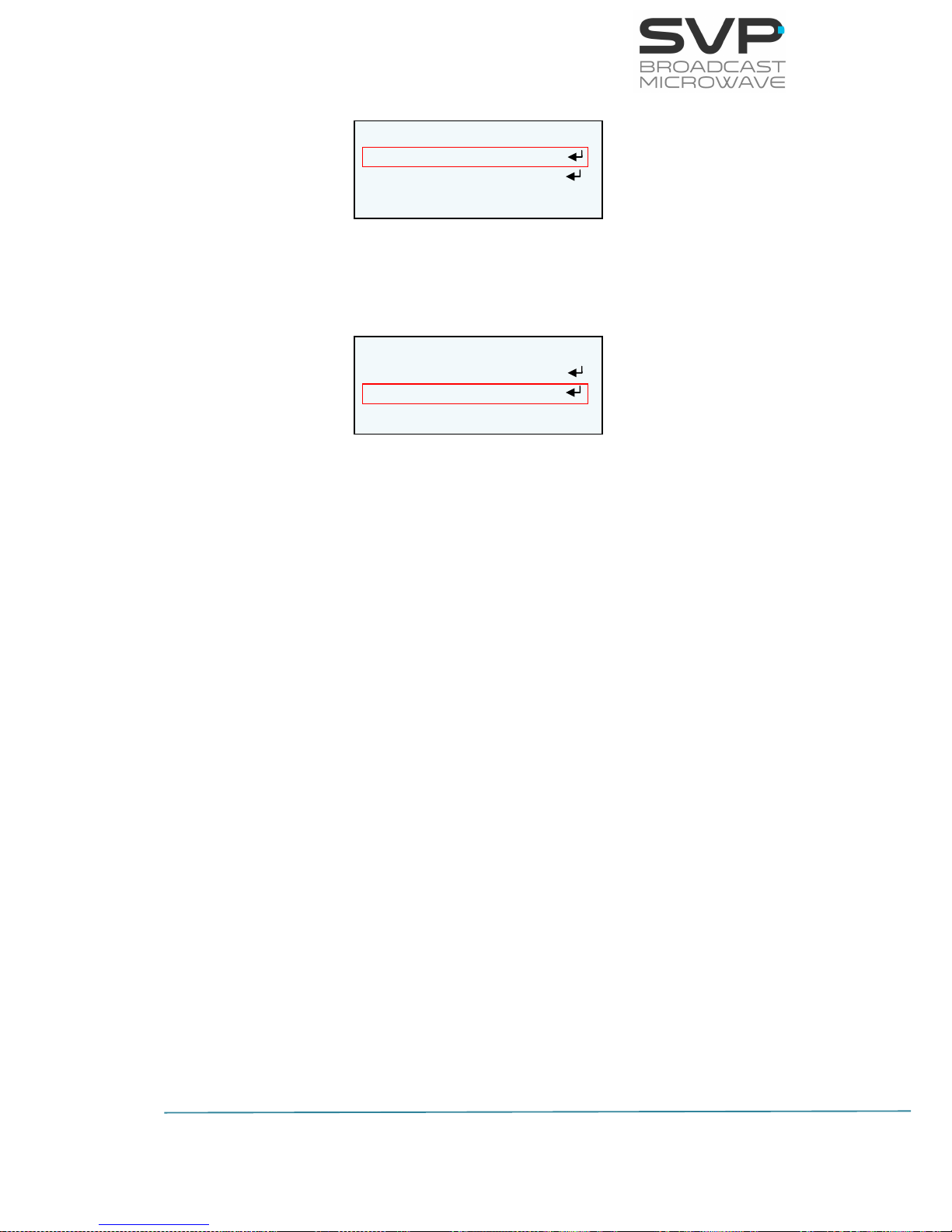
89
HENM-70 Encoder & DVB-S2/S Modulator
USER’S MANUAL V5.6
Figure 5.7 User Pass
8. Select Restore User Pass option to restore de default value of the
administrator’s password.
Figure 5.8 Restore User Pass
Once the IP, Subnet Mask, Gateway, User Password and Admin Password
are set and the laptop or PC is connected to the HENM-70, open the web
browser and tip the IP given to the device.
Press enter button in your computer and then the main screen will appear.
5.2 Web Page Overview
The main menu is set in the upper position of the screen. Once an option is
chosen, it is possible to change a parameter or to see the values of some
options.
In order to modify a parameter, introduce or select the new one and press
enter button. Then the change will be set in the transmitter device.
Next they are shown several screens of the web server and their features.
UNIT ETHERNET
User Pass: ********
Restore User Pas
UNIT ETHERNET
User Pass: ********
Restore User Pas
Page 97
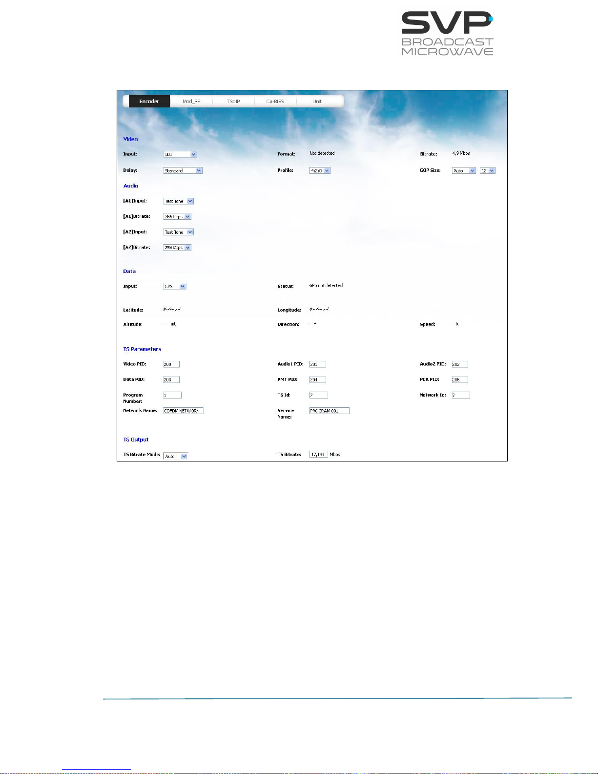
90
HENM-70 Encoder & DVB-S2/S Modulator
USER’S MANUAL V5.6
5.2.1 ENCODER
Figure 5.9 Web Server Encoder screen
5.2.1.1 Video
- Input:
Select the type of the video input. The video input options available
are SDI, HDMI, CVBS, ASI, IP and Test Pattern. In case IP input is
selected, the parameters related to this input can be configured in
the TSoIP screen. (eligible parameter)
- Format:
Here the format of the video input signal is displayed. If there is no
video input then the message ‘not detected’ is displayed. (reading
parameter)
Page 98

91
HENM-70 Encoder & DVB-S2/S Modulator
USER’S MANUAL V5.6
- Bitrate:
In this field the bitrate of the input signal in Mbps is displayed.
(reading parameter)
- Delay:
In this field, the delay of the coding process is configured. The
available options are Standard Delay, Low Delay, Super Low Delay or
Ultra Low Delay. (eligible parameter)
- Profile:
In this field, the codification profile can be configured. The available
options are 4:2:0 and 4:2:2. (eligible parameter)
- GOP Size:
In this field, the group of figures parameter is displayed. It specifies
the order in which intra- and inter-frames are arranged. (eligible
parameter)
The available options are:
Auto
Manual (editable parameter)
Then the GOP size can be configured. The available options are (3, 6,
9, 12, 15, 18, 21, 24, 27, and 30).
5.2.1.2 Audio
- [A1] Input:
Select the type of signal introduced in the audio 1 input. The audio
input options available are Embedded, Analogue, AES-EBU, Test Tone
and None. (eligible parameter)
- [A1] Bitrate:
Select the bitrate for the coding process of the audio 1 signal. The
available options are 128, 192, 256 and 384 Kbps. (eligible
parameter)
- [A2] Input:
Select the type of signal introduced in the audio 2 input. The audio
input options available are Embedded, Analogue, AES-EBU, Test Tone
and None. (eligible parameter)
Page 99

92
HENM-70 Encoder & DVB-S2/S Modulator
USER’S MANUAL V5.6
- [A2] Bitrate:
Select the bitrate for the coding process of the audio 2 signal. The
available options are 128, 192, 256 and 384 Kbps. (eligible
parameter)
5.2.1.3 Data
- Input:
Select the type of data introduced to the device. The available
options are None, GPS and RS232. (eligible parameter)
- Baudrate:
Choose the baudrate of the RS-232 connection. The available options
are 1200, 2400, 4800, 9600, 14400, 19200, 38400, 57600. (eligible
parameter)
- Parity:
Select the parity for the RS-232 connection. The available options are
None, Odd and Even. (eligible parameter)
- Stop Bits:
Establish the number of stop bits for the RS-232 connection. The
available options are 1 and 2. (eligible parameter)
Page 100
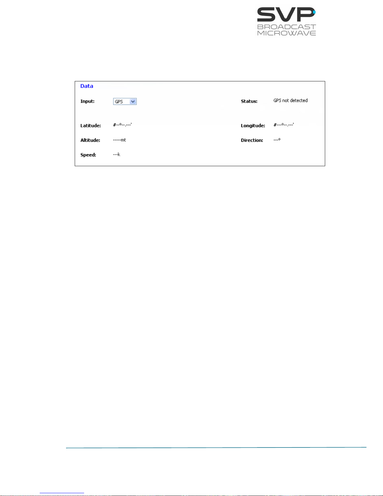
93
HENM-70 Encoder & DVB-S2/S Modulator
USER’S MANUAL V5.6
5.2.1.3.1 GPS
If GPS data is selected and the GPS antenna is connected to the
device, then different parameters as shown in chapter 4 appear:
Figure 5.10 Web Server GPS screen
- Status:
The status of the GPS input is displayed in this field. (reading
parameter)
- Latitude:
It specifies the latitude position of the transmitter. (reading
parameter)
- Longitude:
It specifies the longitude position of the transmitter. (reading
parameter)
- Altitude:
The height of the transmitter from ground in meters is specified in
this value. (reading parameter)
- Direction:
The direction in degrees of the transmitter is shown in this field.
(reading parameter)
- Speed:
The speed of the transmitter in km/h is shown in this field. (reading
parameter)
 Loading...