

SVP HDT-04 User Manual

HDT-04
HIGH POWER
TRANSMITTER
USER´S MANUAL V9.9

Accessories included in this manual
AVS
Airborne Antenna
GPS-02
Antenna
RTC-01
Remote Control
RTC-02
Remote Control

3
HDT-04 High Power Transmitter
USER’S MANUAL V9.9
Contents
Chapter 1: Introduction
This first chapter provides a general description of the HDT-04 high power
transmitter.
Chapter 2: Technical features
This second part offers the transmitter’s physical and environmental
characteristics.
Chapter 3: How to order
The third part provides the user with information on ordering and different
configurations available for these Transmitters.
Chapter 4: Transmitter operation and Menus
This third part provides the user all the necessary information to control and
operate the equipment properly. It is detailed the function of each button on
the keyboard and the information shown on the display, menus, etc.
Chapter 5: GPS Application
In this chapter, the use of the GPS incorporated system and some of its
applications are shown.
Chapter 6: Web Server and SNMP
This chapter provides a detailed description of the Web Server tool. This
feature allows controlling the HDT-04 transmitter through a website.
Chapter 7: Block Diagram
This chapter provides a block diagram of the HDT-04 transmitter internal
performance.
Chapter 8: Equipment Installation
This seventh chapter indicates the available connections of the transmitter
and their characteristics.
Chapter 9: Remote Control
The use of the RTC-01 and RTC-02 device provides a remote connection to
the HDT-04 transmitter.
Chapter 10: Mechanical Dimensions
In this chapter, the mechanical drawing of the units described in this manual
are included.
Chapter 11: Preventive maintenance
This chapter explain the procedure that should be followed during the
transmitter's life.
Chapter 12: Warranty
This chapter contains warranty considerations and conditions.

4
HDT-04 High Power Transmitter
USER’S MANUAL V9.9
Index A: AVS Airborne Antenna User’s Guide
Index B: GPS User’s Guide
Index C: Modulation Standards

5
HDT-04 High Power Transmitter
USER’S MANUAL V9.9
Dear customer,
We would like to thank you for selecting this equipment and welcome you to
the SVP’s growing family of products.
We are sure that the addition of this equipment will cause you a complete
satisfaction in your existing installation.
Please read these instructions carefully, and keep them in hand in case you
have to refer to them.

6
HDT-04 High Power Transmitter
USER’S MANUAL V9.9
About this manual
This user’s guide provides indications and explanations about how to set up
the HDT-04 transmitter easily for the most common use cases.
This document is intended to help first time users:
- To find their way around the GUI.
- To understand the different possibilities of the HDT-04 transmitter.
- To configure the HDT-04 for their specific configurations.
Symbols
The symbols that appear in this manual are:
An information message which indicates explanations for the
proper operation of the equipment.
This symbol advises users that if they do not take, avoid or make
specific actions, several damages could appear in the device.
In the places where this symbol appears it means that by
pressing the Down button of the equipment the user can access
to the next screen.
This symbol means that pressing the OK button in the options
where this symbol appears, the user can access to the submenu
related to that option or can change the value of the
parameter.
<> These symbols mean that the parameter can be modified in the
same screen with the right and left keys.

7
HDT-04 High Power Transmitter
USER’S MANUAL V9.9
Important Notes
1. The HDT-04 transmitter is completely compatible with the DVB-T/T2
Standards, included in the European Standard ETSI EN300744 (DVB-T),
ETSI EN300755 (DVB-T2). It also complies with the ISDB-T International
technical standard (optional).
2. It is important that when the transmitter is switched on, the selected RF
output connection must have the suitable antenna or must be loaded.
3. The HDT-04 transmitter applies a MPEG-4 compression to either HDMI,
composite video or SDI input signals. An MPEG-1 layer 2 compression is
applied to the corresponding 4 analogue audio channels, the 2 stereo SDI
embedded, the HDMI embedded and the AES digital audio signals. The
resulting multiplexed signal is transmitted using COFDM modulation
system.
4. The HDT-04 transmitter is available in different frequency bands from 2
to 5 GHz, for the DVB-T2 and DVB-T RF stage. It can also perform ISDBT with interlaced (optional). The frequency band is defined on the product
P/N.
5. If the RF output is set to DVB-T2 and the bandwidth selected is 1.7 MHz,
then, the device automatically disables the Audio2 and it sets the bitrate
of the Audio1 to 128 kbps.
6. Special care should be taken with SDI cables, quality and length, these
are very important, especially when HD-SDI or 3G SDI signals are
transmitted.
7. If any audio or data channel are not used in a transmission, they should
be disabled, in order to assign that bitrate to the video and achieve a
higher quality transmitted video signal.
8. Only authorized personnel should open the product and any repair or
warranty will be invalidated if the seals are broken.

8
HDT-04 High Power Transmitter
USER’S MANUAL V9.9
First Aid in Case of Electric Shock
DO NOT TOUCH THE VICTIM WITH YOUR BARE HANDS until the circuit is
broken. SWITCH OFF. If this is not possible, PROTECT YOURSELF with DRY
insulating material and pull the victim clear of the conductor.
If breathing has stopped, indicated by unconsciousness, lack of respiratory
movements and a ‘blue’ look to cheeks, lips, ears and nails, START
RESUSCITATION AT ONCE.
EMERGENCY RESUSCITATION – THE EXPIRED AIR METHOD
(Approved by the Royal Life Saving Society)
Chapter 1: If possible, lie the victim on his back with his head slightly higher
than his feet. Clear the mouth and throat of any obvious obstruction.
Chapter 2: Kneel on one side of the victim, level with his head. LIFT THE JAW
AND TILT THE HEAD BACK AS FAR AS POSSIBLE (Figs. 1a and 1b)
Chapter 3: One of the following may happen:
a) Breathing may begin and consciousness returns.
b) Breathing may begin but consciousness NOT
returns. Turn the victim on his side and ensure
that the airway is kept clear.
c) Breathing may return but be NOISY which
means that the airway is not fully clear. Try to
clear the airway.
Chapter 4: IF THERE NO SIGN OF BREATHING:
a) Check that the head is still tilted back.
b) Take a deep breath.
c) Pinch the victim’s nose and blow firmly into his
mouth (Fig. 2). As you do, the chest will RISE.
d) Turn your head away and take another breath,
watching for the chest to FALL (Fig. 3).
Chapter 5: Start with four quick breaths and then continue
with one breath every five seconds (i.e. 12 times a minute).
This should be continued until the victim revives or a doctor
certifies death.
Chapter 6: As consciousness returns the victim will start to
breathe on his own, and a ‘pink’ color replaces the ‘blue’ look:
this is the time to stop resuscitation. Continue to hold his chin
up and so keep the airway clear.
Chapter 7: In the case of injuries to the mouth, it may be necessary to use
mouth-to-nose resuscitation. Seal the victim’s mouth with your cheek and
blow firmly into his nose, proceeding as above.

9
HDT-04 High Power Transmitter
USER’S MANUAL V9.9
Chapter 8: In the case of severe facial injuries, it may be necessary to do a
manual method of artificial respiration (Silvester-Brosch or Holger Nielsen).
Briefly, these methods apply compression to ribcage with the victim lying on
his back (S-B) or face down (H.N.) with associated movement of his arms up
and out. The cycle of movement should take about five seconds, i.e. the
normal breathing phase.
Chapter 9: Whatever the method, it is ESSENTIAL to commence resuscitation
WITHOUT DELAY and to send for medical assistance immediately.
TREATMENT FOR BURNS
If the victim is also suffering from burns, then, without hindrance to
resuscitation, observe the following:
a) DO NOT ATTEMP TO REMOVE CLOTHING ADHERING TO THE BURN.
b) If possible, alleviate the pain from the burnt part by immersing in
cold water.
c) If help as available or as soon as resuscitation is no longer required,
the wound should be covered with a DRY clean dressing.
d) Oil or grease in any form should not be applied.
e) If severely burnt, get the victim to hospital immediately.

9
HDT-04 High Power Transmitter
USER’S MANUAL V9.9
Main Index
Chapter 1: Introduction ................................................................. 12
Chapter 2: Technical Features ....................................................... 16
Chapter 3: How to Order ................................................................ 20
Chapter 4: Transmitter Operation and Menus ................................ 21
4.1 Display ..................................................................................... 21
4.2 LEDs ........................................................................................ 24
4.3 Keyboard ................................................................................. 25
4.4 Menus Scheme .......................................................................... 28
4.5 Menu Navigation ....................................................................... 33
4.6 Menu Structure ......................................................................... 34
Encoder Menu ..................................................................... 35
4.6.1.1 SDI Video Input ...................................................... 39
4.6.1.2 HDMI 1/2 Video Input ............................................ 42
4.6.1.3 CVBS Video Input ................................................... 45
4.6.1.4 ASI Video Input ...................................................... 47
4.6.1.5 Generator Video Input ............................................ 48
4.6.1.6 Audio1 Embedded ................................................... 50
4.6.1.7 Audio1 Analogue ..................................................... 51
4.6.1.8 Audio1 AES-EBU ...................................................... 52
4.6.1.9 Audio1 Generator ................................................... 53
4.6.1.10 Audio2 Embedded ................................................. 54
4.6.1.11 Audio2 Analogue ................................................... 55
4.6.1.12 Audio2 AES-EBU .................................................... 56
4.6.1.13 Audio2 Generator.................................................. 57
4.6.1.14 Data ...................................................................... 58
4.6.1.15 Encoder Output ..................................................... 61
4.6.1.16 TS Parameters ...................................................... 62
4.6.1.17 Scrambler ............................................................. 65
4.6.1.18 Remux (optional) .................................................. 67
RF Menu ............................................................................. 69
4.6.2.1 DVB-T2 ................................................................... 69
4.6.2.2 DVB-T2 Maximum Bitrates ...................................... 72
4.6.2.3 DVB-T ..................................................................... 73
4.6.2.4 DVB-T Useful Bitrate ............................................... 76
Unit Menu ........................................................................... 78
4.6.3.1 Profile ..................................................................... 78
4.6.3.1.1 RTC-01 Remote Control Screen ............................ 79
4.6.3.1.2 RTC-02 Remote Control Screen ............................ 80
4.6.3.2 RTC-01 Config ......................................................... 81
4.6.3.3 RTC-02 Config ......................................................... 87
10
HDT-04 High Power Transmitter
USER’S MANUAL V9.9
4.6.3.4 Alarms .................................................................... 88
4.6.3.5 Monitor ................................................................... 89
4.6.3.6 Remote ................................................................... 90
4.6.3.7 Miscellaneous ......................................................... 93
4.6.3.8 Firmware ................................................................ 96
Chapter 5: GPS Application .......................................................... 100
5.1 Introduction ............................................................................ 100
5.2 Main Screen ............................................................................ 100
5.3 GPS Transmitter Screen ........................................................... 101
5.4 Application Example 1 – Constant Positioning.............................. 103
Chapter 6: Web Server and SNMP ................................................ 104
6.1 Introduction ............................................................................ 104
6.2 Web Page Overview ................................................................. 107
ENCODER ............................................................................ 108
RF ...................................................................................... 116
6.2.2.1 DVB-T .............................................................................. 117
6.2.2.2 DVB-T2 ............................................................................ 118
UNIT ................................................................................... 120
6.3 Web Page Setup Notes ............................................................. 124
6.4 SNMP ..................................................................................... 125
SNMP Commands ................................................................. 126
Chapter 7: Block Diagram ............................................................ 127
7.1 Introduction ............................................................................ 127
Chapter 8: Equipment Installation ............................................... 130
8.1 Introduction ............................................................................ 130
8.2 Connections ............................................................................ 130
Power supply [J4] .............................................................. 132
8.2.1.1 DC Power supply ............................................................. 132
RF output [J5] ................................................................... 133
RF Auxiliar output [J7] ........................................................ 133
GPS Antenna Input [J6] ...................................................... 133
DVB-ASI Transport Stream ................................................. 134
8.2.5.1 ASI Input [J12] ............................................................... 134
8.2.5.2 ASI Output [J8] .............................................................. 134
SDI [J11]/ HDMI [J10] ....................................................... 135
RTC connection [J2] ........................................................... 136
Audio – Ethernet [J3] ......................................................... 137
USB connection [J9] ........................................................... 138
8.3 Electrical wiring diagram .......................................................... 138
HDT-04 & RTC without antenna actuator ............................... 139
HDT-04 & RTC with antenna actuator ................................... 140

11
HDT-04 High Power Transmitter
USER’S MANUAL V9.9
Chapter 9: Remote Control .......................................................... 141
Chapter 10: Mechanical Dimensions ............................................ 156
10.1 HDT-04 ................................................................................ 157
10.2 RTC-01 ................................................................................. 158
10.3 RTC-02 ................................................................................. 159
10.4 CLTX-04 ............................................................................... 160
10.5 CLTX-04 Support Installation .................................................. 161
10.6 GPS Antenna & Receiver ......................................................... 162
Chapter 11: Preventive Maintenance ........................................... 163
11.1 Maintenance Schedule ............................................................ 163
11.2 Maintenance Procedures ......................................................... 163
11.3 Spare Parts ........................................................................... 163
Chapter 12: Warranty .................................................................. 164
12.1 Warranty information ............................................................. 164
12.2 Claim for damage in shipment ................................................. 164
12.3 Return procedures ................................................................. 164
Annex A: AVS Airborne Antenna User’s Guide .............................. 165
A.1 Description ............................................................................. 165
A.2 Technical Specifications ............................................................ 166
Annex B: GPS-02 Receiver ........................................................... 167
A.1 Description ............................................................................. 167
A.2 Technical Specifications ............................................................ 168
Annex B: Modulation Standards ................................................... 170
B.2 DVB-T .................................................................................... 170
B.2.1 How Does It Work ................................................................ 170
B.3 DVB-T2 .................................................................................. 171
B.3.1.1 How Does It Work .............................................................. 171
B.3.1.2 DVB-T2 New Features ........................................................ 172
B.3.2 DVB-T vs DVB-T2 ................................................................. 173

12
HDT-04 High Power Transmitter
USER’S MANUAL V9.9
Chapter 1: Introduction
The HDT-04 is the new high power transmitter developed by SVP Broadcast
Microwave which provides an output power of 10 W in the frequency ranges
of 2,010 to 2,390 MHz, 2,300 to 2,700 MHz, 4,400 to 5,000 MHz or 5,000 to
5,300 MHz and an output power of 5 W in the frequency range of 3,300 to
3,600 MHz.
Its feature H.264 encodes for 3G, high definition (HD) and standard definition
(SD) signals with ultra-low latency. H.264 transmission is possible using 40%
lower bitrate than conventional MPEG-2 systems.
This new generation transmitter accepts analogue video, 3G/HD/SD-SDI and
HDMI video input signals. Analogue, SDI embedded, HDMI embedded and
AES/EBU audio inputs are available as standard. User data or GPS data can
be transmitted over the data channel.
The ASI output enables the user to use the transmitter as a standalone
encoder.
The HDT-04 transmitter performs DVB-T2, DVB-T and ISDB-T (optional),
modulations.
Moreover, it expands the possibilities of COFDM digital links on the market
using linearization technology to minimize distortion and to provide superior
signal quality for complex multicarrier modulations.
Control, operation and monitoring of the HDT-04 transmitter are very
friendly. All the parameters can be configured in field. A wide range of
accessories allow using this equipment in many different applications.
An excellent design, mechanical and electronic assembly make the HDT-04 a
robust and reliable solution.
For applications of high security, the HDT-04 transmitter has the option of
AES-128 and AES-256 encryption.

13
HDT-04 High Power Transmitter
USER’S MANUAL V9.9
Features
Input video signals, composite video, 3G–SDI, HD-SDI, SD-SDI or HDMI are
MPEG-4 encoded, together with 4 analogue audios, 2 stereo AES/EBU
channels, HDMI embedded or 4 digital audios embedded on the SDI signal.
The video formats can be 1080p, 1080i, 720p, 576i or 480i. This transmitter
also has a test pattern and a test tone generator available.
This device has a data channel available that allows transmitting user data or
GPS data as well as a Transport Stream ASI input so it can be used as a
repeater.
The encoder uses a H.264/MPEG-4 Part 10 video compression that provides
output bitrates from 1 Mbps to 100 Mbps and a MPEG-1 Layer II audio
compression which supplies different audio bit rates (128, 192, 256 or 384
Kbps).
Encoded signals can be encrypted using BISS-1, BISS-E, AES-128 and AES256 (optionally) scrambling system. The encrypted signal will only be
received by the receivers that have a valid descrambling key.
The transmitter system operation is very easy. It has a display and a
keyboard which make possible the configuration and monitoring of every
parameter of the equipment.
The equipment is fed with DC power supply from 12 to 36V. It has good
harmonic rejection and isolator for protection against high VSWR.
It also has a waterproof radiator that dissipates heat through a fan. The fan
is activated when the temperature exceeds 40ºC.
DVB-T2 features
This transmitter uses COFDM (Coded Orthogonal Frequency Division
Multiplexing) modulation system (1K, 2K) which provides superior signal
robustness and a higher link performance. This technology provides the
operators efficient means to overcome the challenges of NLOS propagation
and mobile channel propagation.
COFDM spread spectrum modulation system distributes the data over a large
number of closely-spaced carriers, for example, 1705 carriers in 2K mode.
The data is divided into several parallel data streams, one for each carrier, so
that each carrier transports a lower data rate and the symbol duration is
longer. Each carrier is then modulated with a QPSK, 16QAM, 64QAM or
256QAM scheme with a constellation rotation.

14
HDT-04 High Power Transmitter
USER’S MANUAL V9.9
COFDM modulated signal, since it uses a low symbol rate modulation scheme
(i.e. the symbols are relatively long compared to the channel time
characteristics), suffers less from inter symbol interference caused by
multipath propagation. As the duration of each symbol is long, it is feasible
to insert a guard interval between the COFDM symbols, thus eliminating the
inter symbol and co-channel interference. So, if one carrier’s information is
lost, only a small part of the whole information will be lost.
Besides, in COFDM the sub-carrier frequencies are chosen so that the subcarriers are orthogonal to each other, thus cross-talk, the interference
between the sub-channels, is eliminated. Furthermore, the orthogonality
allows high spectral efficiency.
On the other hand, COFDM system is invariably used in conjunction with
channel coding (forward error correction). The error correction code used in
this equipment is Reed-Solomon coding, which is concatenated with LDPC,
and there is an additional interleaving between the two layers of coding. Error
correcting codes build redundancy into the transmitted data stream. This
redundancy allows bits that are in error or even missing to be corrected at
the receiver.
The European ETSI EN 300755 standard defines the following LDPC coding
rates: 1/2, 3/5, 2/3, 3/4, 4/5, 5/6. There is a compromise between the coding
rate (signal robustness) and the transmitted bit rate. If the coding rate is
higher the signal transmission is more robust (1/2 is the most robust) but the
bit rate that the system is able to transmit is lower.
The modulation scheme used on each COFDM sub-carrier (QPSK, 16QAM,
64QAM and 256 QAM) is also thus related to the signal robustness and the
transmitted bit rate. QPSK is the most robust and 256QAM is able to transport
the highest bit rate.
Besides, the system can define 3 guard intervals: 1/8, 1/16 and 1/32. The
guard interval is used to reduce inter symbol interferences due to the
multipath propagation.
In addition, it also provides several bandwidths: 1.7, 6, 7 and 8 MHz, for
different applications.
The maximum bit rate achieved is 46 Mbps.

15
HDT-04 High Power Transmitter
USER’S MANUAL V9.9
DVB-T features
The RF stage of the HDT-04 transmitter for DVB-T is the same as the one
described for DVB-T2. The only differences are found in the modulation part,
as it is commented below.
The HDT-04 transmitter uses COFDM (Coded Orthogonal Frequency Division
Multiplexing) modulation system (2K mode).
The available modulations are: QPSK, 16QAM or 64QAM. Of them, the most
robust one is QPSK and the one with the maximum bit rate is 64 QAM.
The European ETSI EN 300744 standard defines the following convolutional
coding rates: 1/2, 2/3, 3/4, 5/6, 7/8.
The modulation scheme used on each OFDM sub-carrier (QPSK, 16QAM and
64QAM) is also thus related to the signal robustness and the transmitted bit
rate. QPSK is the most robust and 64QAM is able to transport the highest bit
rate.
Besides, the system can define 3 guard intervals: 1/8, 1/16 and 1/32.
Finally, the maximum bit rate achieved is 31.67 Mbps.

16
HDT-04 High Power Transmitter
USER’S MANUAL V9.9
Chapter 2: Technical Features
RF Stage DVB-T2, DVB-T and ISDB-T (optional)
Frequency ranges: 2,010 – 2,390 MHz
2,300 – 2,700 MHz
3,300 – 3,600 MHz
4,400 – 5,000 MHz
5,000 – 5,300 MHz
Output Power:
Harmonics suppression: 60 dB
Protection capabilities: Reverse DC
High Reverse power
Fan characteristics: Operating Voltage Range: 14 to 27.6 VDC
Rated Input Power: 2.40 W
Speed: 7.000 rpm
Noise: 40.5 dBA
Video:
Inputs: 3G-SDI SMPTE-425M-A (299M)
HD-SDI SMPTE-292M (299M)
SD-SDI SMPTE-259M (272M)
HDMI (1.4a)
Composite video (PAL/NTSC)
Formats: 1080p (1920x1080) – 23.98/24/25/
29.97/30/50/59.94/60 Hz
1080i (1920x1080) – 50/59.94/60 Hz
720p (1280x720) – 23.98/24/25/29.97/
30/50/59.94/60 Hz
576i (720x576) – 50 Hz
480i (720x480) – 59.94 Hz
Low
Mid
High
10 W (2, 4 and 5 GHz)
30 dBm
37 dBm
40 dBm
5 W (3 GHz)
30 dBm
35 dBm
37 dBm

17
HDT-04 High Power Transmitter
USER’S MANUAL V9.9
Audio:
Input: SDI embedded / HDMI embedded
AES Digital / Analogue
Analogue: 2 Stereo / 4 Mono
Line, Micro Dynamic and Micro with
Phantom
SDI embedded: 1 Group (4 audio channels)
AES/EBU: 2 Stereo channels
User Data
Data channel: User data (RS232) or GPS (NMEA at 4800
baudrate)
Data rate: 1.200 to 57.600 bps
ASI
Input and Output: ASI Transport Stream (EN50083-9)
Test Signals
Video: Bars with a moving icon
Audio: 4 Audio tones
Encoder
Video compression: H.264/MPEG-4 Part 10
Profile: High 422, High, Main
Level: 3.0/3.1/3.2/4.0/4.1
Latency: Ultra Low delay: 33 ms
Audio compression: MPEG-1 Layer II
Audio bit rate: 128, 192, 256 or 384 Kbps
Output bit rate: 1 Mbps – 100 Mbps

18
HDT-04 High Power Transmitter
USER’S MANUAL V9.9
Encryption
BISS: BISS-1 and BISS-E
AES: AES-128 and AES-256 (Optional)
Modulation
DVB-T2: COFDM 1K, 2K
QPSK, 16 QAM, 64 QAM, 256 QAM
Constellation rotation
LDPC FEC: 1/2, 3/5, 2/3, 3/4, 4/5, 5/6
IG: 1/8, 1/16, 1/32
Bandwidth: 1.7, 6, 7, 8 MHz
Max. bitrate: 46 Mbps
DVB-T: COFDM 2K mode
QPSK, 16 QAM, 64 QAM
FEC: 1/2, 2/3, 3/4, 5/6, 7/8
IG: 1/8, 1/16, 1/32
Bandwidth: 5, 6, 7, 8 MHz
Max. bitrate: 31.67 Mbps
*ISDB-T with interlaced (optional).
Control & Monitorization
Control Interfaces: Front panel & display
Web browser interface
SNMP
RTC-01
RTC-02
Pre-sets: 7 user defined pre-sets
Monitoring: Encoding, modulation, frequency and
output power, alarms and warnings.
Power Supply
DC input: 12 – 36 VDC
Power Consumption: 100 W
Recovery time: 10.5 seconds
(It is the time the equipment needs
to recover an image in case of a cut
in the power supply)

19
HDT-04 High Power Transmitter
USER’S MANUAL V9.9
Mechanical
Size: 122 x 147.5 x 220 mm (WxHxD)
Weight: 3.3 kg
Environmental
Aeronautical: RTCA / DO-160 compliant
Temperature range: -20º to 50ºC
20
HDT-04 High Power Transmitter
USER’S MANUAL V9.9
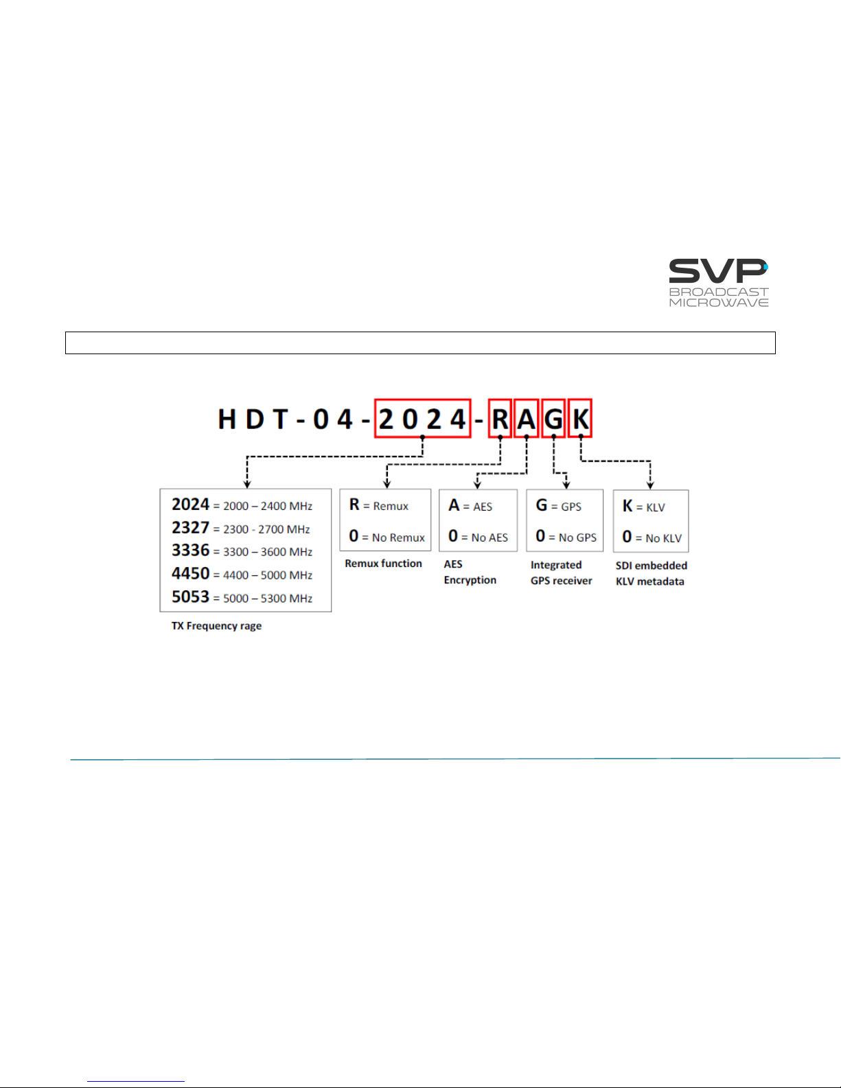
Chapter 3: How to Order

21
HDT-04 High Power Transmitter
USER’S MANUAL V9.9
Chapter 4: Transmitter Operation and Menus
This third chapter provides the user all the necessary information to control,
configure and operate the equipment properly.
4.1 Display
To turn the equipment on and off, press ON/OFF button.
When a video, audio or data input has been selected, a character connected
to this input is displayed in the main screen.
Below, the main screen of the HDT-04 transmitter is shown.
When an option is selected, the main screen displays these parameters:
▪ Frequency (MHz)
▪ Transmission Standard (DVB-T2, DVB-T)
▪ Output power (dBm)
▪ Reflected power (%)
▪ FFT number of points
▪ Bandwidth (MHz)
▪ Modulation Scheme
▪ FEC
F: 2350,00MHz DVBT2
P: 40dBm R:13%2K B8
Q16 3/5 1/8 8.2
GGGGKR 576/50i 420S
Frequency
Output Power
Modulation Scheme
Video Input Selection
Audio Input Selection
FFT
Data Input Selection
FEC
Input Video Signal Format
Transmission Standard
Bandwidth
Bit rate
Latency
Guard Interval
Encoder Video Profile
Reflected Power
Figure 4.1: HDT-04 front panel / Main screen explanation
KLV Status Indicator
Remux Status Indicator

22
HDT-04 High Power Transmitter
USER’S MANUAL V9.9
▪ Guard Interval
▪ Transmitted bit rate (Mbps)
▪ Video Input selection
Possibilities: CVBS, HDMI, SDI, DVB-ASI Transport Stream or Generator.
Behaviour of the corresponding character: If the character is static then it
means presence of that signal. If the character blinks, then it means
absence of that signal.
▪ Audio status indication: If audio 1 or 2 are not darkened then they are
enabled. On the other hand, if audio 1 or 2 are darkened then they are
disabled.
▪ Data status indication: If this field is not darkened then it means that data
is enabled. On the other hand, if this value is darkened it means that data
is disabled. Moreover, in case this field is static, its meaning is presence
of the data whereas if this field is blinking, it means absence of the data.
▪ KLV status indicator: If this field is not darkened then it means that KLV
metadata is enabled. On the other hand, if this value is darkened it means
that metadata is disabled. Moreover, in case this field is static, its meaning
is presence of the data whereas if this field is blinking, it means absence
of the KLV metadata.
▪ Remux status indicator: This field indicates if Remux function is enabled
or disabled.
▪ Input video signal format.
▪ Encoder Video Profile (4.2.0 or 4.2.2).
▪ Latency (Standard delay, Low delay or Super Low Delay)
- Standard Delay (Lipsync < 10 ms)
- Low delay (Lipsync < 10 ms) → 3 frame
- Super Low Delay (Lipsync < 10 ms) → 2 frames
- Ultra Low Delay (Lipsync = 20ms) → 1 frame

23
HDT-04 High Power Transmitter
USER’S MANUAL V9.9
Below, the correspondence between the input and character displayed is
shown.
Video
CVBS
C
HDMI
H
SDI S
ASI A
Test Pattern
G
Audio
Embedded
E
AES/EBU
U
Analogue
A
Test Tone
G
Data
RS232
D
GPS
G
KLV
KLV
K
Remux
Remux
R
Table 4.1: Correspondence between the input and the character displayed
24
HDT-04 High Power Transmitter
USER’S MANUAL V9.9
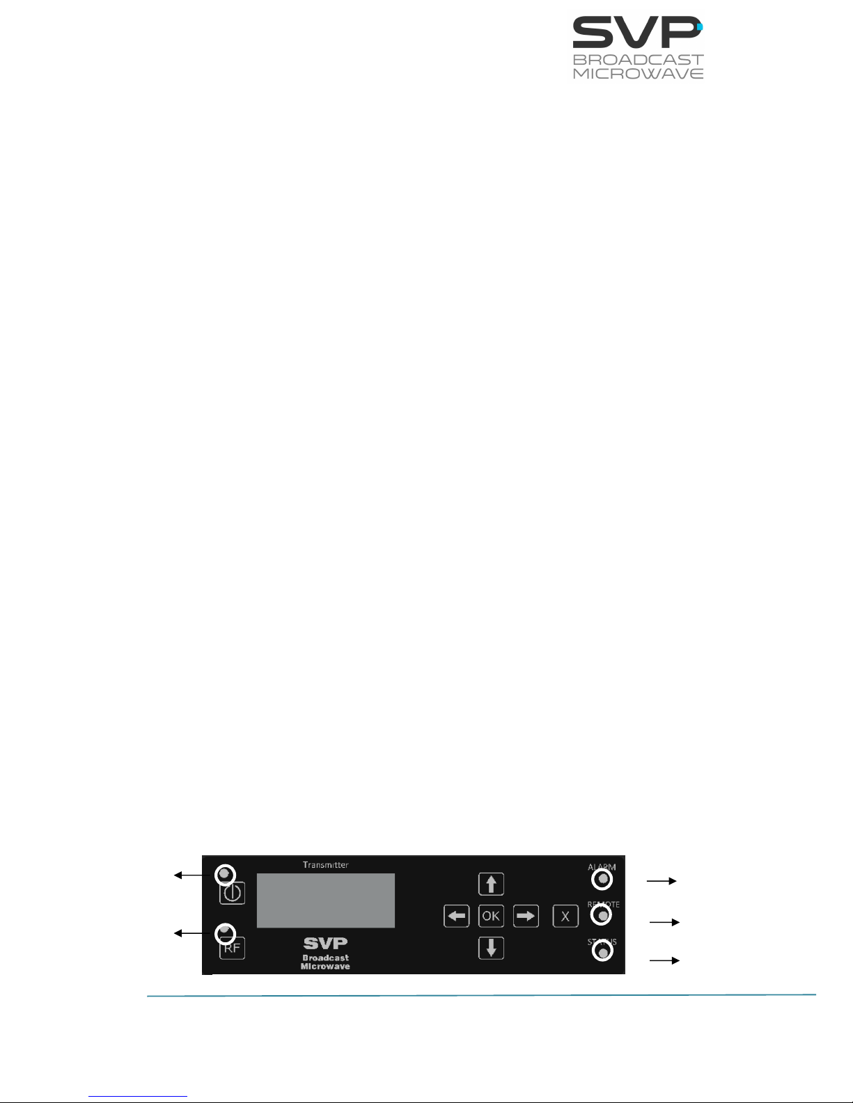
4.2 LEDs
The HDT-04 transmitter has 5 Leds on its front panel that show the
information detailed below.
The ON/OFF provides the following information:
▪ If the Led blinks in red, there is power into the unit but it is turned off.
▪ The Led lights up in green when the equipment is turned on.
The RF LED provides the following information:
▪ The Led lights up in green when the equipment transmits RF signal, RF
stage is active.
The ALARM LED provides the following information:
▪ The different alarms that can appear in the transmitter are:
▪ Voltage High.
▪ Voltage Low.
▪ Temperature High.
▪ Direct Power.
▪ Reverse Power.
▪ PA Not Forward
▪ ASI Overflow.
The different warnings that can appear in the transmitter are:
▪ No SDI Input.
▪ No HDMI Input.
▪ No CVBS Input.
▪ No ASI Input.
▪ No KLV.
The REMOTE LED provides the following information:
▪ The LED lights up when the remote control via Webserver has been
established.
The STATUS LED provides the following information:
▪ The LED lights up when the transmitter is working properly.
REMOTE LED
ALARM LED
STATUS LED
Figure 4.2: front panel LED indication
ON/OFF LED
RF LED

25
HDT-04 High Power Transmitter
USER’S MANUAL V9.9
4.3 Keyboard
ON/OFF Button
To switch the equipment on and off, press this button. When the equipment
is turned on, the display will show the start-up message (model and version
of the equipment), and then it will display the main screen.
If the power fails while the equipment is operating, it will restart automatically
when the power returns, not being necessary to press the on/off button again.
OK Button
This button is used to:
▪ Enter to submenus and change parameters. So as to access to a submenu,
OK button must be pressed. Moreover, in the fields where the enter
symbol appears, by pressing the OK button the user can change the
value of the selected parameter. Besides, so as to save the introduced
value, the OK button must be pressed.
▪ In case of being in the main screen, pressing the OK button the user can
access to the alarms screen where there are the different alarms that are
taking place. So as to return to the main screen, the cross button must be
pressed.
OK
Figure 4.3: ON/OFF button
Figure 4.4: OK Button
26
HDT-04 High Power Transmitter
USER’S MANUAL V9.9
Cross Button
This button is used to:
▪ Enter from the equipment main screen to the setup menu and vice versa.
▪ Exit equipment’s submenus.
▪ This button allows the user to access to the main screen from the alarms
screen.
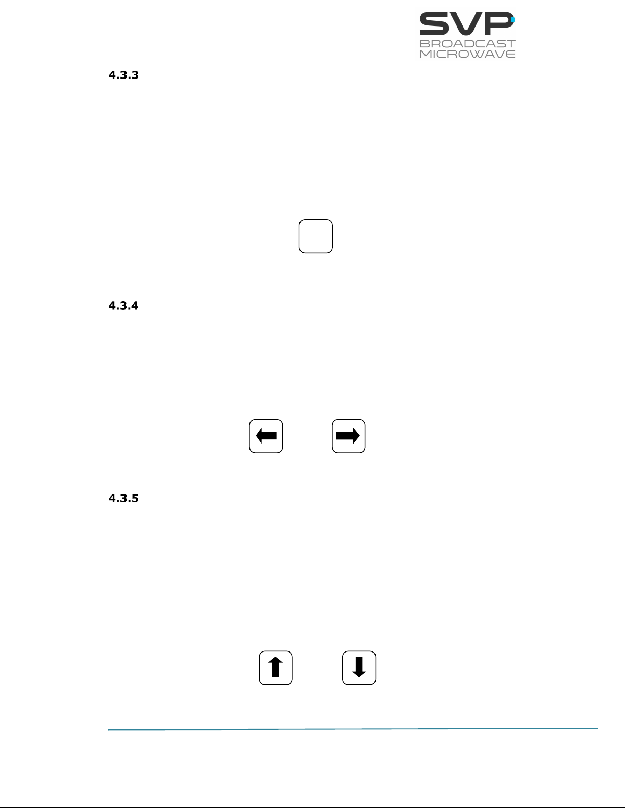
Left and Right Button
These buttons are used to:
▪ Once the parameter to change has been selected, they are used to move
the cursor towards the digit immediately on the left or right and to select
a parameter from different options.
Up and Down Button
▪ The up and down arrow buttons allow the navigation in the main menu
and the rest of submenus. Using this buttons, the user can enter to the
submenu or change a parameter. Once selected, the OK button must be
pressed.
▪ This buttons are also used to change, for example, the frequency and PID
parameter’s values. Pressing up and down arrows the value of those
parameters can be changed, increased or decreased respectively.
X
Figure 4.5 Cross Button
Figure 4.6: Left and Right buttons
Figure 4.7: Up and Down buttons

27
HDT-04 High Power Transmitter
USER’S MANUAL V9.9
By pressing the RF button, RF output is enabled or disabled. The RF LED
indicates the status of the RF output. To enable or disable the RF output, just
press the RF button. It is important that before pressing this button, the
selected RF output must be conveniently loaded and there is no reflected
signal.
In case the device is switched off with the RF output enabled then, when it is
switched on again it is necessary to push again this button so as to enable
this feature.
However, if power supply fails when RF output is enabled then, once power
supply returns it is not necessary to push this button because RF output will
continue being enabled.
RF
Figure 4.8: RF On/Off button

28
HDT-04 High Power Transmitter
USER’S MANUAL V9.9
4.4 Menus Scheme
There is one menu in this transmitter that allows the user to change the
transmitter’s parameters and configure them.
To enter the menu of this equipment the cross button must be pressed. In
case it is wanted to return again to the main screen from the menu, the cross
button must be pressed. Furthermore, in case of being in the submenus area,
returning to the mainly screens are achieved by pressing the cross button as
much times as it is needed.
In the next page it is shown a scheme that specifies the different menu
options available.
29
HDT-04 High Power Transmitter
USER’S MANUAL V9.9
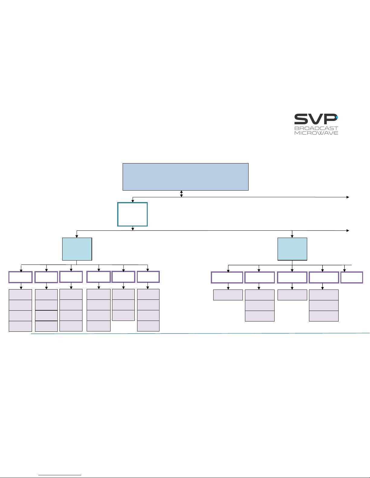
HDT-04 MENU STRUCTURE
continued
MAIN SCREEN
Frequency, standard, power, FFT, bandwidth,
modulation, FEC, GI, latency, output bitrate,
audio and video status, profile
Format
Encoder
Video
SDI
HDMI 1
CVBS
ASI
GEN
L Type
Format
Status
Forma
Delay
Profile
Delay
Profile
Profile
Delay
Format
Bitrate
Profile
Delay
Analogue
Embedded
AES-EBU
Tone.Gen
None
Audio 1
Bitrate
Bitrate
Bitrate
Bitrate
Frequency
Level
continued
Format
GOP
GOP
GOP
GOP
R Type
HDMI 2
Delay
Profile
Format
GOP
 Loading...