

HDE-70
H.264 – 4:2:2 - 10 bits
Decoder
MANUAL V6.9

I
HDE-70 H.264 – 4:2:2 – 10 bits Decoder
MANUAL V6.9
Contents
Chapter 1: Introduction
This first chapter provides a general description of the HDE-70 decoder
equipment.
Chapter 2: Technical features
This second part offers a detailed description of the decoder’s physical and
environmental characteristics.
Chapter 3: Decoder operation and Menus
This third part provides the user all the necessary information to control and
operate the equipment properly. It is detailed the function of each button on
the keyboard. It is also explained how the information is shown on the
display, decoder menus, etc.
Chapter 4: GPS
This fourth chapter indicates the operation of the HDE-70 GPS system and
specifies the parameters that are shown in the GPS screen.
Chapter 5: Web Server
This fifth chapter provides a detailed description of the Web Server tool.
This feature allows controlling the HDE-70 decoder through a website.
Chapter 6: Equipment Installation
This chapter indicates the available connections of the decoder, their
characteristics and the installation of the decoder.

II
HDE-70 H.264 – 4:2:2 – 10 bits Decoder
MANUAL V6.9
Dear Customer,
We would like to thank you for selecting this equipment and welcome you to
the SVP’s growing family of products.
We are sure that the addition of this equipment will cause you a complete
satisfaction in your existing installation.
Please read these instructions carefully, and keep them in hand in case you
have to refer to them.
III
HDE-70 H.264 – 4:2:2 – 10 bits Decoder
MANUAL V6.9
About this manual
This user’s guide provides indications and explanations about how to set up
the HDE-70 decoder easily for the most common use cases.
This document is intended to help first time users:
- To find their way around the GUI.
- To understand the different possibilities of the HDE-70 decoder.
- To configure the HDE-70 for their specific configurations.
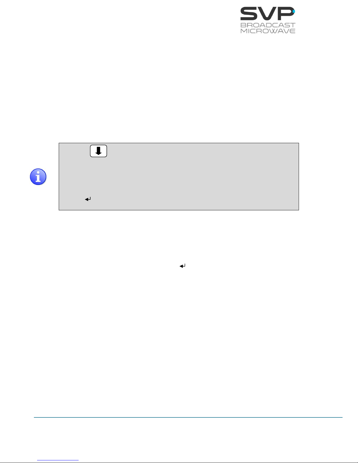
Symbols
The symbols that appear in this manual are:
An information message which indicates explanations for the
proper operation of the equipment.
It advices users that if they do not take, avoid or make specific
actions, several damages could appear in the device.
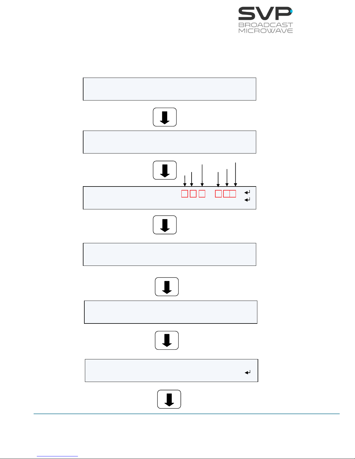
In the places where this symbol appears it means that by
pressing the Down button of the equipment the user can
access to the next screen.
This symbol means that pressing the OK button in the options
where this symbol appear, the user can access to the submenu
related to that option or can change the value of the
parameter.
<> These symbols mean that the parameter can be modified in the
same screen with the right and left keys.

IV
HDE-70 H.264 – 4:2:2 – 10 bits Decoder
MANUAL V6.9
Important Notes
1. This device has the ASI and IP outputs available when the input is ASI.
Besides, it has also the ASI output available when the input is IP.
2. The decoder must be well chilled. Some space must be left next to the
sides of the HDE-70 decoder for ventilation purposes. This is especially
important when it is installed in a rack case.
3. If you wish to install the rack mount demodulator unit horizontally,
guides should be used, due to the weight of the equipment.
4. It is not advisable to use a power supply lead with a cross-section less
than that of the lead supplied, since this would cause a drop in the
supply voltage and deficient operation of the equipment.
5. Only authorized personnel should open the product and any repair or
warranty will be invalidated if the seals are broken.
V
HDE-70 H.264 – 4:2:2 – 10 bits Decoder
MANUAL V6.9
First Aid in Case of Electric Shock
DO NOT TOUCH THE VICTIM WITH YOUR BARE HANDS until the circuit is
broken. SWITCH OFF. If this is not possible, PROTECT YOURSELF with DRY
insulating material and pull the victim clear of the conductor.
If breathing has stopped, indicated by unconsciousness, lack of respiratory
movements and a ‘blue’ look to cheeks, lips, ears and nails, START
RESUSCITATION AT ONCE.
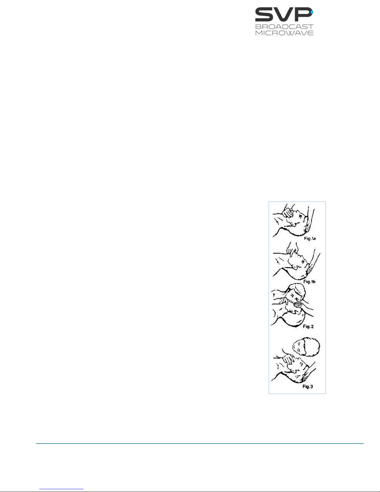
EMERGENCY RESUSCITATION – THE EXPIRED AIR METHOD
(Approved by the Royal Life Saving Society)
1. If possible, lie the victim on his back with his head slightly higher
than his feet. Clear the mouth and throat of any obvious obstruction.
2. Kneel on one side of the victim, level with his head. LIFT THE JAW
AND TILT THE HEAD BACK AS FAR AS POSSIBLE (Figs. 1a and 1b)
3. One of the following may happen:
a) Breathing may begin and consciousness
returns.
b) Breathing may begin but consciousness NOT
returns. Turn the victim on his side and ensure
that the airway is kept clear.
c) Breathing may return but be NOISY which
means that the airway is not fully clear. Try to
clear the airway.
4. IF THERE NO SIGN OF BREATHING:
a) Check that the head is still tilted back.
b) Take a deep breath.
c) Pinch the victim’s nose and blow firmly into his
mouth (Fig. 2). As you do, the chest will RISE.
d) Turn your head away and take another breath,
watching for the chest to FALL (Fig. 3).
5. Start with four quick breaths and then continue with
one breath every five seconds (i.e. 12 times a
minute). This should be continued until the victim
revives or a doctor certifies death.
6. As consciousness returns the victim will start to
breathe on his own, and a ‘pink’ color replaces the
‘blue’ look: this is the time to stop resuscitation.
Continue to hold his chin up and so keep the airway clear.
7. In the case of injuries to the mouth, it may be necessary to use
mouth-to-nose resuscitation. Seal the victim’s mouth with your cheek
and blow firmly into his nose, proceeding as above.

VI
HDE-70 H.264 – 4:2:2 – 10 bits Decoder
MANUAL V6.9
8. In the case of severe facial injuries it may be necessary to do a
manual method of artificial respiration (Silvester-Brosch or Holger
Nielsen). Briefly, these methods apply compression to ribcage with
the victim lying on his back (S-B) or face down (H.N.) with associated
movement of his arms up and out. The cycle of movement should
take about five seconds, i.e. the normal breathing phase.
9. Whatever the method, it is ESSENTIAL to commence resuscitation
WITHOUT DELAY and to send for medical assistance immediately.
TREATMENT FOR BURNS
If the victim is also suffering from burns, then, without hindrance to
resuscitation, observe the following:
a) DO NOT ATTEMP TO REMOVE CLOTHING ADHERING TO THE BURN.
b) If possible alleviate the pain from the burnt part by immersing in
cold water.
c) If help as available or as soon as resuscitation is no longer required
the wound should be covered with a DRY clean dressing.
d) Oil or grease in any form should not be applied.
e) If severely burnt, get the victim to hospital immediately.

1
HDE-70 H.264 – 4:2:2 – 10 bits Decoder
MANUAL V6.9
Main Index
Chapter 1: Introduction ....................................................................... 4
Chapter 2: Technical features ............................................................... 5
Chapter 3: Decoder Operation and Menus .............................................. 8
3.1 Display and LEDs ..................................................................... 8
3.1.1 1st Main Screen for the ASI Input ......................................... 9
3.1.2 1st Main Screen for the IP Input .......................................... 10
3.2 Decoding Example .................................................................. 11
3.3 TFT Screen ............................................................................ 12
3.4 Speaker & Headphones audio outputs ....................................... 12
3.5 LEDs ..................................................................................... 13
3.6 Front panel ............................................................................ 14
3.6.1 ON/OFF Button ................................................................. 14
3.6.2 OK Button ........................................................................ 15
3.6.3 Cross Button .................................................................... 15
3.6.4 Left and Right Button ........................................................ 15
3.6.5 Up and Down Button ......................................................... 16
3.7 Menus ................................................................................... 17
3.7.1 Menu Navigation ............................................................... 21
3.7.2 Menu Structure ................................................................. 22
3.7.2.1 Input Select Menu ....................................................... 23
3.7.2.1.1 ASI ....................................................................... 23
3.7.2.1.2 IP ......................................................................... 25
3.7.2.2 Decoder Menu ............................................................. 30
3.7.2.2.1 Mode Screen .......................................................... 31
3.7.2.2.2 Decoder Video Format Screen ................................... 33
3.7.2.2.3 Decoder Encoding System Screen ............................. 34
3.7.2.2.4 Decoder Audio Status Screen ................................... 35
3.7.2.2.5 Decoder Data Screen ............................................... 36
GPS Screen ...................................................................... 37
3.7.2.2.6 Decoder GenLock Screen ......................................... 39
3.7.2.2.7 Decoder Frame Error Screen .................................... 39
3.7.2.2.8 Decoder Frame Without Signal Screen ....................... 40
3.7.2.3 Autotracking Menu ....................................................... 41
3.7.2.4 CA-BISS Menu ............................................................ 45
3.7.2.5 IP Output Menu ........................................................... 47
3.7.2.6 Unit ........................................................................... 50
3.7.2.6.1 Unit Video Monitor Screen ........................................ 51
3.7.2.6.2 Unit Audio Monitor Screen ........................................ 51
3.7.2.6.3 Unit Alarms Screen ................................................. 52

2
HDE-70 H.264 – 4:2:2 – 10 bits Decoder
MANUAL V6.9
3.7.2.6.4 Unit Monitor Screen ................................................. 53
3.7.2.6.5 Unit Webserver & SNMP Screen ................................ 55
3.7.2.6.6 Unit Miscellaneous Screen ........................................ 57
3.7.2.6.7 Unit Firmware Screen .............................................. 61
Chapter 4: GPS ................................................................................. 66
4.1 Introduction ........................................................................... 66
4.2 Main Screen ........................................................................... 66
4.3 GPS Screen ............................................................................ 67
4.4 Application example ................................................................ 68
Chapter 5: Web Server ....................................................................... 70
5.1 Introduction ........................................................................... 70
5.2 Web Page Overview ................................................................ 73
5.2.1 ASI INPUT ........................................................................ 73
5.2.2 IP INPUT .......................................................................... 73
5.2.3 DECODER......................................................................... 76
5.2.4 Autotracking ..................................................................... 81
5.2.5 DESCRAMBLING ................................................................ 86
5.2.6 IP Output ......................................................................... 87
5.2.7 UNIT ............................................................................... 89
5.3 Web Page Setup Notes ............................................................ 95
5.4 SNMP .................................................................................... 95
5.4.1 SNMP commands .............................................................. 96
Chapter 6: Equipment Installation ....................................................... 97
6.1 Introduction ........................................................................... 97
6.2 Connections ........................................................................... 97
6.2.1 Power supply .................................................................... 98
AC Power supply ....................................................................... 98
DC Power supply ..................................................................... 100
6.2.2 DVB-ASI Transport Stream ............................................... 101
DVB-ASI Transport Stream Input .............................................. 101
DVB-ASI Transport Stream Output ............................................ 101
6.2.3 Video Outputs ................................................................. 102
6.2.4 Genlock ......................................................................... 103
Genlock Input ......................................................................... 103
Genlock Output ....................................................................... 103
6.2.5 Transport Stream over IP ................................................. 104
Transport Stream over IP Input and Output ................................ 104
6.2.6 Audio output .................................................................. 105
6.2.7 GPS / Data ..................................................................... 106
GPS/Data Input ....................................................................... 106
GPS / DATA Output.................................................................. 108

3
HDE-70 H.264 – 4:2:2 – 10 bits Decoder
MANUAL V6.9
6.2.8 Remote control ............................................................... 110
6.2.9 USB............................................................................... 111

4
HDE-70 H.264 – 4:2:2 – 10 bits Decoder
MANUAL V6.9
Chapter 1: Introduction
The new HDE-70 features H.264 and MPEG-2 decoding for high definition
(HD) and standard definition (SD) signals. H.264 compression makes
possible HD signal transmission and reception using 40% lower bitrate than
conventional MPEG-2 systems. Moreover, HDE-70 works in 4:2:2 with 10
bits.
This device decodes input TS signals of up to 320 Mbps and offers the
highest video quality with minimum end to end latency available in the
market, 33ms. For added security, encrypted transmitted signal can be
decrypted using BISS or AES decryption technology.
It features Video over IP and remote control via the Ethernet port. So, this
decoder provides a choice of IP or ASI network interfaces allowing
deployment of services over IP networks or traditional video networks.
The HDE-70 has been designed to be 1U rack mountable.
SVP has reached the state of the art and the HDE-70 decoder has been
designed to be used in broadcast, security and military applications.

5
HDE-70 H.264 – 4:2:2 – 10 bits Decoder
MANUAL V6.9
Chapter 2: Technical features
Decoder:
H.264: Profiles: Baseline, Main, High
High 422
Support 10 bits
Level: 4.1 – 4.2
Latency: 33 ms and Standard Delay
MPEG-2: Profiles: 422P@HL, MP@HL, 422P@ML,
MP@ML
Latency: 33 ms and Standard Delay
Audio Decoder: MPEG-1 Layer I/II
Max. input bitrate: 320 Mbps
Genlock input: Black burst or tri-level, Genlock loop
Decryption:
BISS: BISS-1 and BISS-E
AES: AES-128 and AES-256 (Optional)
Video:
Outputs: 3G-SDI
HD-SDI
SD-SDI
HDMI (1.4)
Composite video (PAL/NTSC)
Formats: 1080p (1920x1080) – 23.98/ 24/ 25/
29.97/ 30/ 50/ 59.94/ 60 Hz
1080i (1920x1080) – 50/ 59.94/ 60 Hz
720p (1280x720) – 23.98/ 24/ 25/ 29.97/
30/ 50/ 59.94/ 60 Hz
576i (720x576) – 50 Hz
480i (720x480) – 59.94 Hz

6
HDE-70 H.264 – 4:2:2 – 10 bits Decoder
MANUAL V6.9
Audio:
Output: HDMI/ SDI embedded/ AES Digital/
Analogue
Analogue: 2 Stereo/ 4 Mono
SDI embedded: 1 Group (4 audio channels)
AES/EBU: 2 Stereo channels
Data Channels:
Data channel: User data or GPS
Data rate: 1.200 to 57.600 bps
ASI and IP:
Outputs and Inputs: ASI Transport Stream (EN50083-9)
Transport Stream over IP
(SMTP2022/CoP3) - FEC
Max. TS packets / IP packet: 7
Control and Monitorization:
Control Interfaces: Front panel & display
Web browser
SNMP
Monitoring: Decoder parameters
Alarms, warnings and logbook
Video & Audio: TFT Video screen 2”
2x Stereo loud-speakers
Earphone output
Power Supply:
AC input: 100 to 240 V
DC input: 11 to 36 V
Consumption: < 30 W

7
HDE-70 H.264 – 4:2:2 – 10 bits Decoder
MANUAL V6.9
Mechanical:
Size: 1 RU, 255 mm (10 inches) depth
Weight: 3 Kg (6.6 lb)
Environmental:
Temperature range: -10 to 45 ºC
Height: 4.500 m
Humidity: 95%

8
HDE-70 H.264 – 4:2:2 – 10 bits Decoder
MANUAL V6.9
Chapter 3: Decoder Operation and Menus
This section contains all the necessary information to operate, control and
configure the HDE-70 decoder.
3.1 Display and LEDs
To turn the equipment on and off, press the On/Off button. When the
equipment is turned on, the display will show the start-up message (model
of the equipment), and then it will display the main screen where there are
displayed the most important parameters of the received signal.
Next, there are shown the linkages between the input and the character
displayed in the principal screen:
Audio
A
Data
DATA
D
GPS
G
Table 3.1 Linkages between the input and the character displayed
Next, the main screen for each input type (ASI or IP) is shown:

9
HDE-70 H.264 – 4:2:2 – 10 bits Decoder
MANUAL V6.9
3.1.1 1
st
Main Screen for the ASI Input
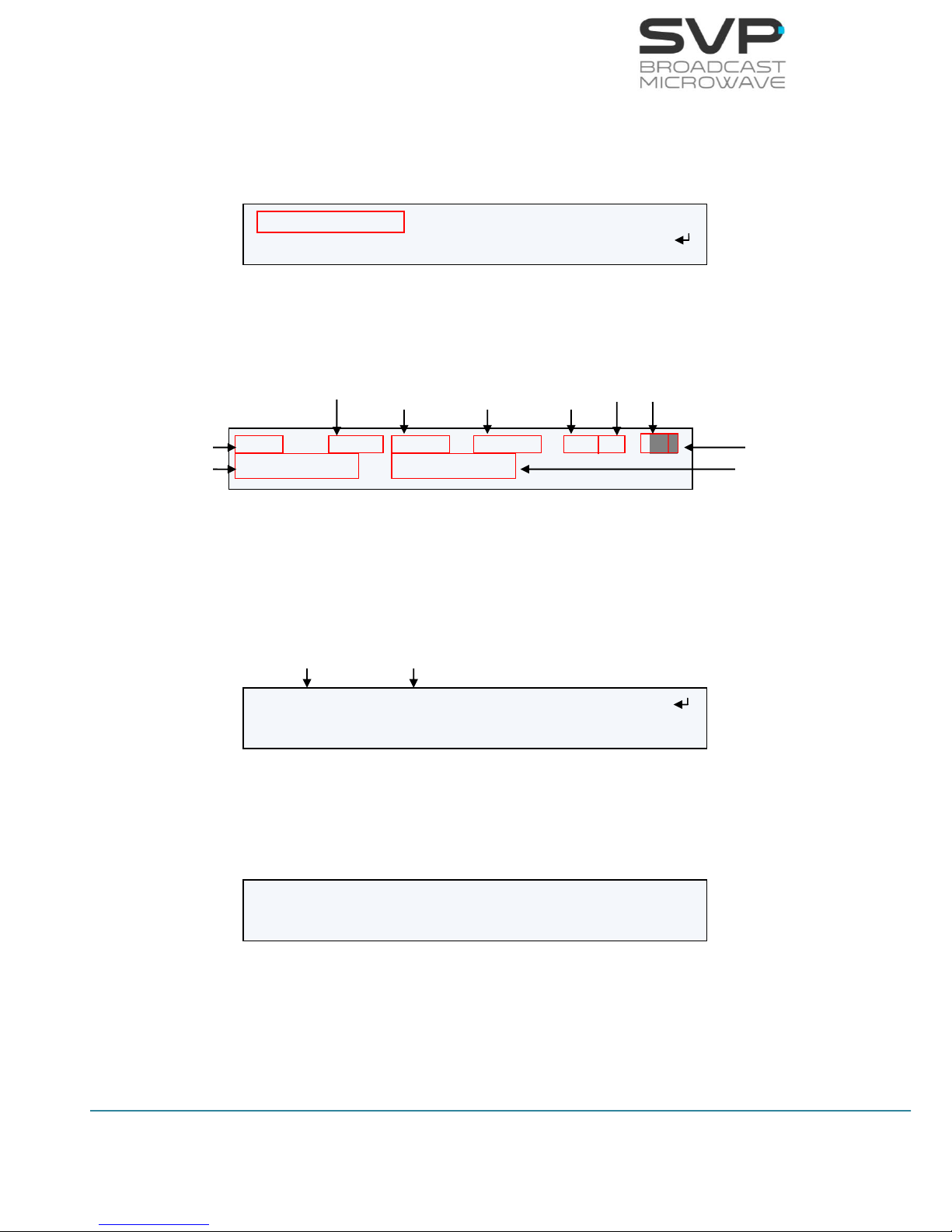
In the table below, the function of each parameter is explained. These
values are numbered in the order they appear in the main screen (the first
one is the one allocated in the first line beginning from the left, the second
one the next at the right …).
Parameter nº
Function
1
Input signal type (ASI)
2
Received bitrate (Mbps)
3
Video Codification (H.264 / MPEG-2)
4
Video Format (1080p, 1080i, 720p, 576i, 480i)
5
Video options:
Profile (4:2:0 or 4:2:2)
Delay (Standard (S), Low delay (L) or Super Low delay (SL))
6
Characters 1 (Audio 1) and 2 (Audio 2):
Audio status indication (Audio 1 and 2 not darkened -> audio
received / darkened -> audio not received)
Character 3:
Data status indication (not darkened -> data received /
darkened -> data not received)
7
Number of services available
8
Name of the selected service
Table 3.2 Main screen for ASI input
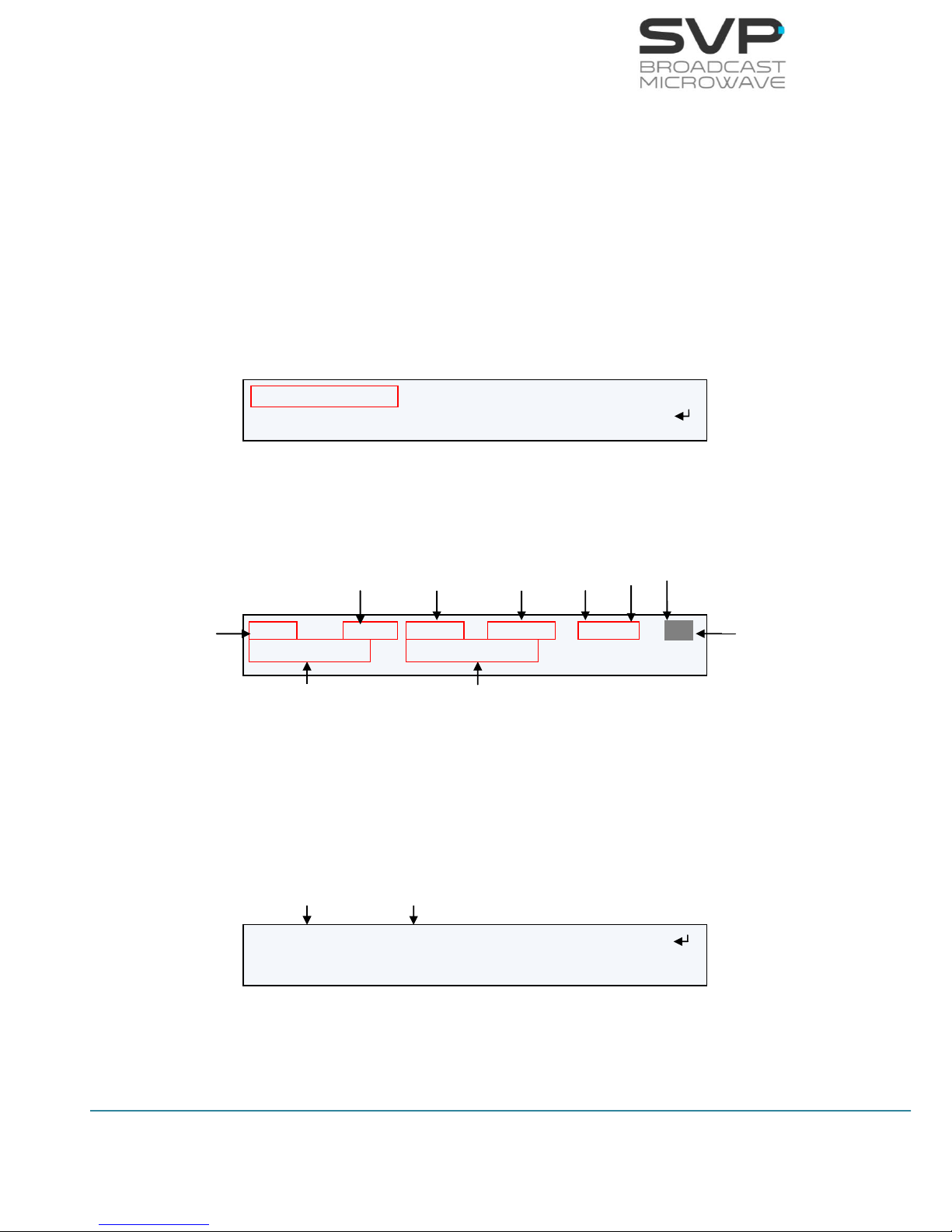
Figure 3.1 Main screen 1 ASI
ASI: 9.9Mb H.264 576/50i 420/S AAD
(06 services) PROGRAM 001
Received Signal Type
Bitrate
Video
Codification
Output Video
Signal Format
Profile
Delay
Audio Status
Data Status
Number of
services
Name of the
Selected service

10
HDE-70 H.264 – 4:2:2 – 10 bits Decoder
MANUAL V6.9
3.1.2 1
st
Main Screen for the IP Input
In the table below, the function of each parameter is explained. These
values are numbered in the order they appear in the main screen (the first
one is the one allocated in the first line beginning from the left, the second
one the next at the right …).
Parameter nº
Function
1
Input signal type (IP)
2
Received bitrate (Mbps)
3
Video Codification (H.264 / MPEG-2)
4
Video Format (1080p, 1080i, 720p, 576i, 480i)
5
Video options:
Profile (4:2:0 or 4:2:2)
Delay (Standard (S), Low delay (L) or Super Low delay (SL))
6
Characters 1 (Audio 1) and 2 (Audio 2):
Audio status indication (Audio 1 and 2 not darkened -> audio
received / darkened -> audio not received)
Character 3:
Data status indication (not darkened -> data received /
darkened -> data not received)
7
Number of services available
8
Name of the selected service
Table 3.3 Main screen for IP input
Figure 3.2 Main screen 1 IP
IP: 7.8Mb H.264 576/50i 420/S AAD
(06 services) PROGRAM 001
Received Signal Type
Bitrate
Audio/Video
Codification
Output Video
Signal Format
Decoder
Profile
Delay
Audio Status
Data Status
Number of
services
Name of the
Selected service
11
HDE-70 H.264 – 4:2:2 – 10 bits Decoder
MANUAL V6.9
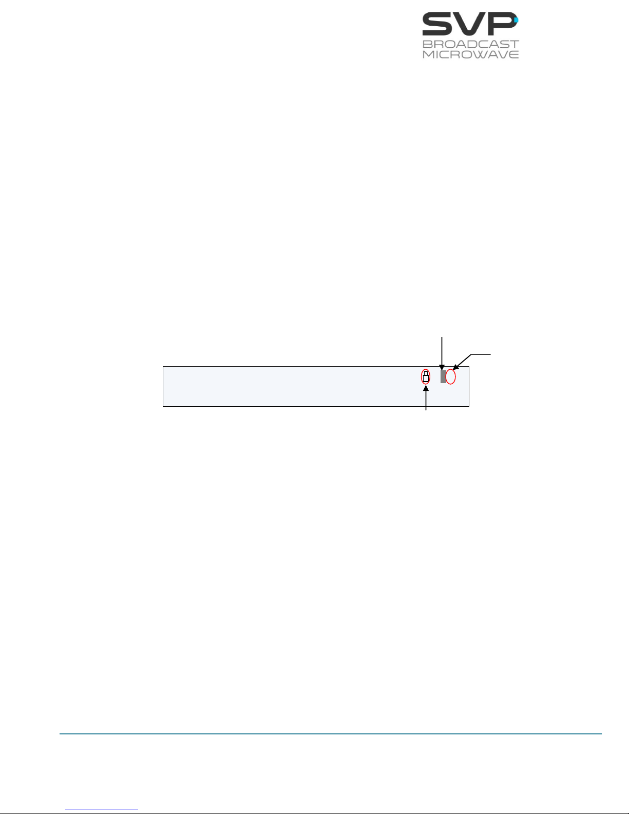
3.2 Decoding Example
Next, a reception example and the image that appears in the monitor
screen are shown.
Example (IP)
Setup:
Received signal type (IP)
Bitrate: 8 Mbps
Audio/Video codification: MPEG2
Input video signal format: 576/50i
Decoder profile: 4:2:0
Delay: Low delay
Audio status: Audio1 analogue (enabled), Audio2 AES/EBU (disabled)
Data status: GPS
Number of services: 6 services
Name of the selected program: PROGRAM 001
Figure 3.3 HDE-70 Monitor screen. Example
The audio 2 status indicator is darkened because it is only receiving one
audio signal. If two audio signals are received, then this field will not be
darkened.
The data status field indicates with a darkened character that no data is
being received. If the ‘G’ character appears and it is not blinking, it means
that the GPS in the transmitter is connected to the satellites.
If before the audio status a padlock appears, it means that the received
signal is encrypted.
IP: 8.0Mb MPEG2 576/50i 420/L AAG
(06 services) PROGRAM 001
darkened
blinking
padlock

12
HDE-70 H.264 – 4:2:2 – 10 bits Decoder
MANUAL V6.9
3.3 TFT Screen
The HDE-70 decoder has a TFT 2” screen which allows the user watching
the received video signal throughout this screen.
This TFT screen receives the video signal from the Composite Video output.
While there is no video signal received, the TFT screen will show an image
of the company.
Next, a figure in which the TFT screen appears is shown.
Figure 3.4 TFT 2” screen
3.4 Speaker & Headphones audio outputs
The HDE-70 decoder has two possible direct audio outputs from which the
user can hear the audio signal directly. These outputs consist of a connector
to which headphones can be connected and two speakers, one situated in
the right side of the device and the other one in the left side. These audio
outputs can be configured following these steps (they are detailed in
chapter 3.7.2 in the Unit Menu section):
1. Go to the Unit menu.
2. Go to the Audio Monitor option and select Audio 1 or Audio 2 with
right and left keys.
3. Press the OK button to configure the Audio Volume and the Audio
Speaker.
4. Select Audio Volume and press right and left keys to configure the
intensity of the volume.
5. Select Audio Speaker and press right and left keys to enable or
disable the two speakers.
Figure 3.5 Speakers & Headphones audio outputs
TFT 2” screen
Right Speaker
Headphones
connector
Left Speaker
13
HDE-70 H.264 – 4:2:2 – 10 bits Decoder
MANUAL V6.9
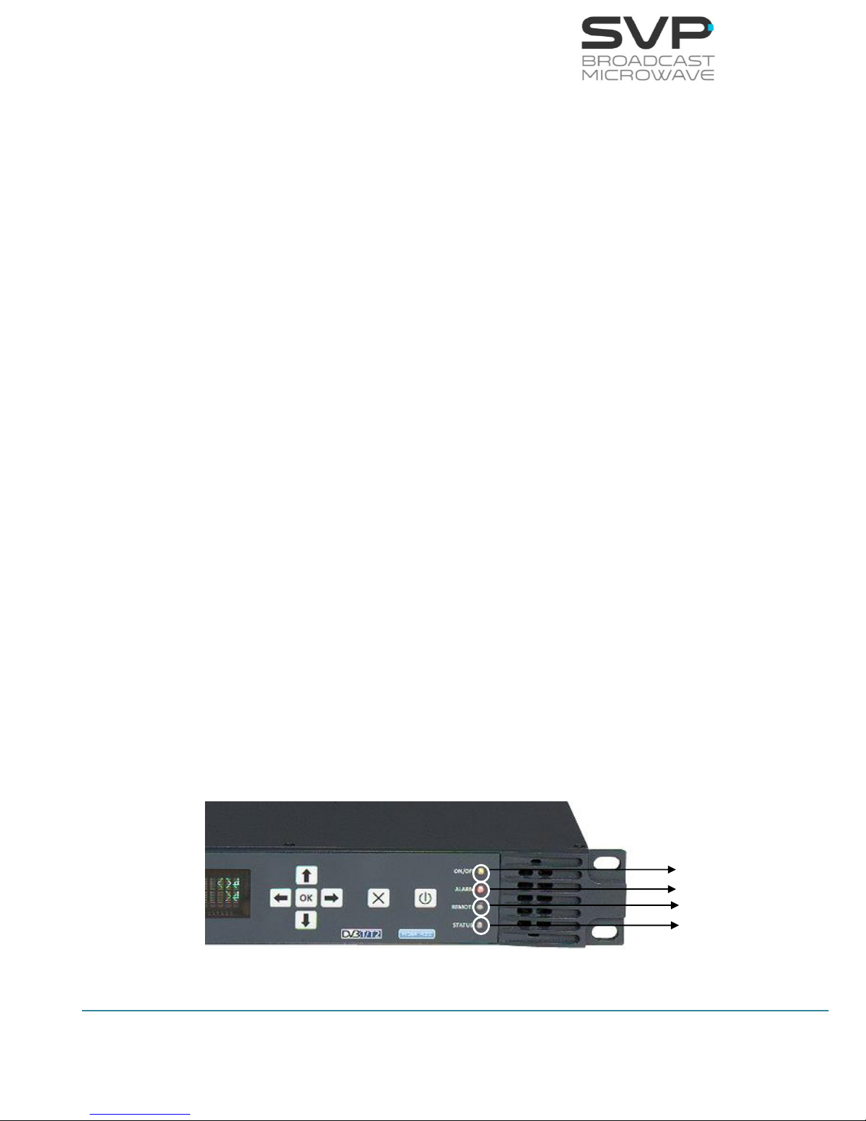
3.5 LEDs
The HDE-70 decoder has 4 Leds on its front panel that show the information
detailed below.
The ON/OFF provides the following information:
If the Led is off, the equipment is not being fed.
If the Led flickers are red, there is power into the equipment but it is
turned off.
The Led lights up in green when the equipment is turned on.
The ALARM LED provides the following information:
The Led lights up in red when any alarm occurs.
The different alarms that can appear in the device are:
- Input Signal Not Present
- No Video Present
- DC Voltage Low
- DC Voltage High
- High Temperature
The REMOTE LED provides the following information:
The Led lights up in green when the user is connected remotely to the
device.
The STATUS LED provides the following information:
The LED lights up when a change in the configuration of the device is
being processed.
Figure 3.6 HDE-70 LEDs
ON/OFF LED
ALARM LED
REMOTE LED
STATUS LED
14
HDE-70 H.264 – 4:2:2 – 10 bits Decoder
MANUAL V6.9
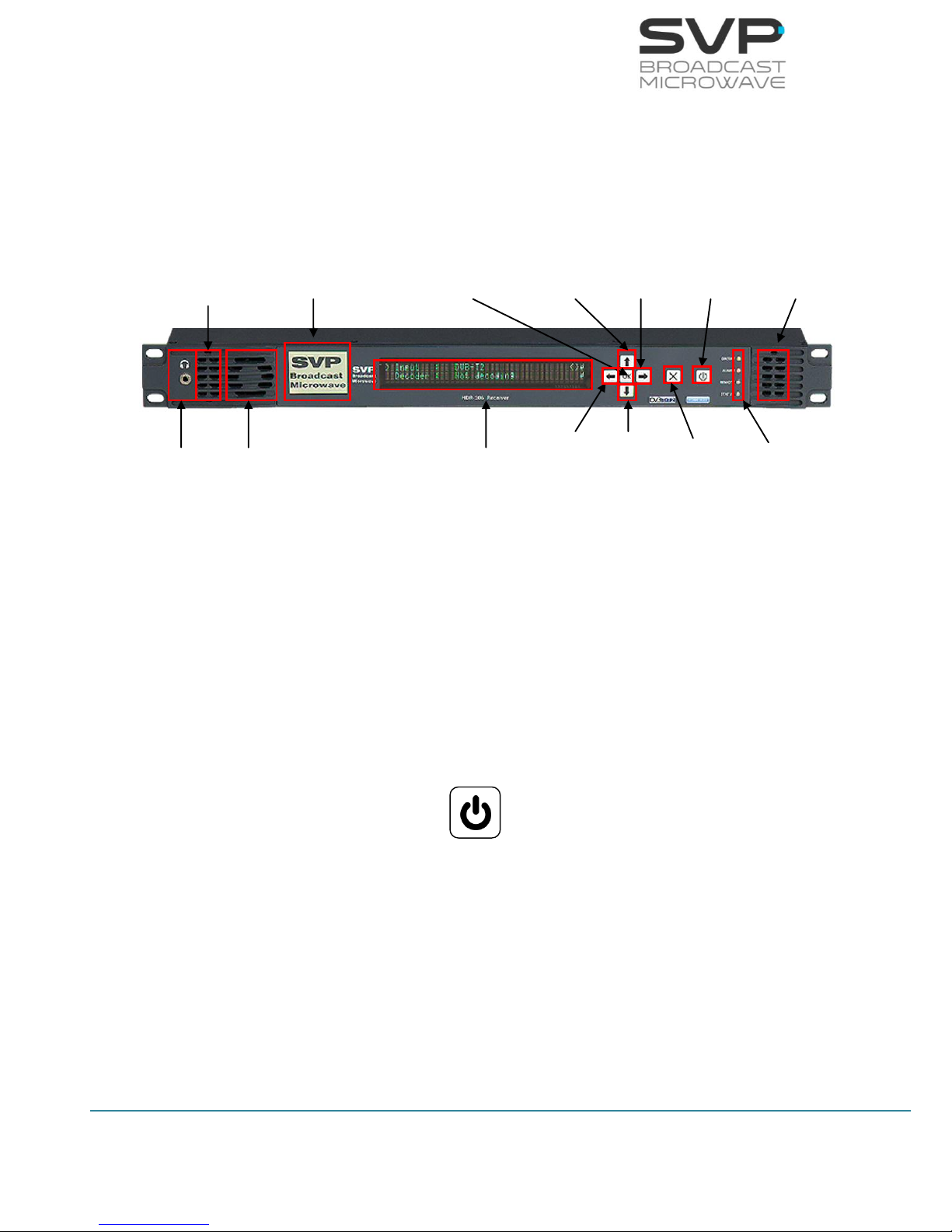
3.6 Front panel
The HDE-70 decoder is configured following a menus structure on the
display. The front panel has 7 buttons to enter and exit the equipment
control menus and submenus and to navigate through them.
The function of each button is detailed in the following sections.
Figure 3.7 HDE-70 front panel
3.6.1 ON/OFF Button
To turn the equipment on and off, press this button. When the equipment is
turned on, the display will show the start-up message (model and version of
the equipment), and then it will display the main screen.
If the power fails while the equipment is operating, it will restart
automatically when the power returns, not being necessary to press the
on/off button again.
Figure 3.8 ON/OFF button
Headphones
Fan
Left
Speaker
TFT 2”
Screen
Display
Left
Button
Up
Button
Down
Button
Cross
Button
Right
Button
ON/OFF
Button
LEDs
Right
Speaker
OK
Button

15
HDE-70 H.264 – 4:2:2 – 10 bits Decoder
MANUAL V6.9
3.6.2 OK Button
This button is used to:
Enter to submenus and change parameters. So as to access to a
submenu, OK button must be pressed. Moreover, in the fields where the
enter symbol appears, by pressing the OK button the user can
change the values of the parameter selected. Besides, so as to save the
introduced value, the OK button must be pressed.
Figure 3.9 OK button
3.6.3 Cross Button
This button is used to:
Enter from the equipment main screen to the setup menu and vice
versa.
Exit equipment submenus.
Figure 3.10 Cross button
3.6.4 Left and Right Button
These buttons are used to:
Once the parameter to change has been selected, they are used to move
the cursor towards the digit immediately on the left or right and to select
a parameter from different options.
Figure 3.11 Left and Right buttons
OK
X

16
HDE-70 H.264 – 4:2:2 – 10 bits Decoder
MANUAL V6.9
3.6.5 Up and Down Button
The up and down arrow buttons allow navigation in the main menu and
the rest of submenus. These buttons are selected to enter to a submenu
or to change a parameter. Once selected, the OK button must be
pressed.
These buttons are also used to change some parameters values.
Pressing up and down arrows the value of those parameters can be
changed, increased or decreased respectively.
Figure 3.12 Up and Down buttons

17
HDE-70 H.264 – 4:2:2 – 10 bits Decoder
MANUAL V6.9
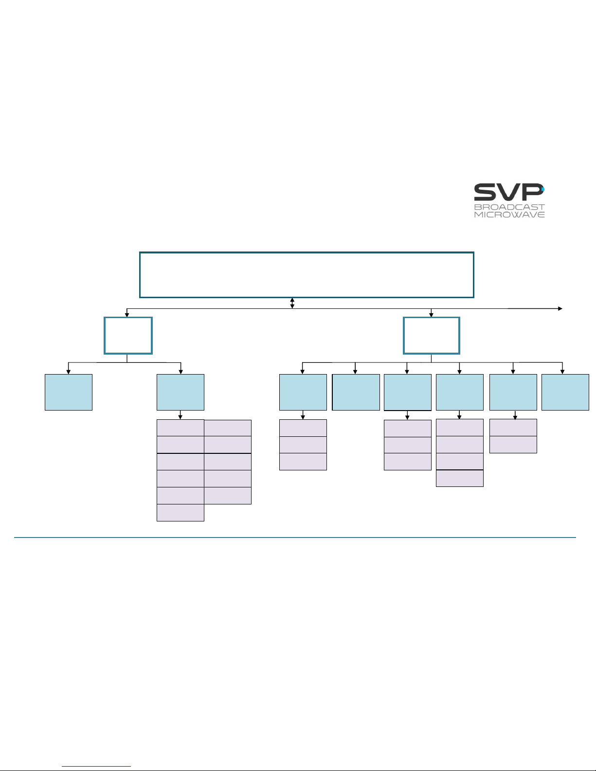
3.7 Menus
Using the menu of this decoder the user can change decoder parameters
and configure them.
When the decoder is firstly switched on, the main screen appears.
To enter the menu of this equipment the cross button must be pressed. In
case it is wanted to return to the principal screen from the menu, the cross
button must be pressed. Furthermore, in case of being in the submenus
area, returning to the mainly screens is achieved by pressing the cross
button as much times as it is needed.
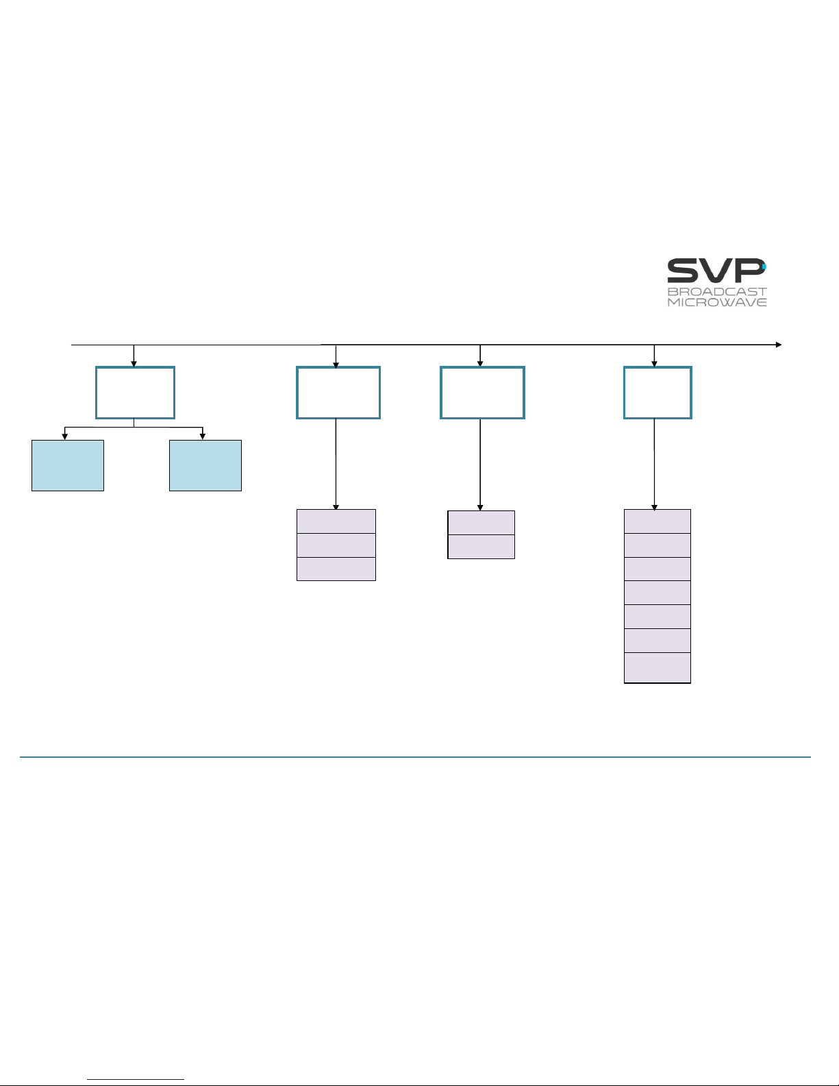
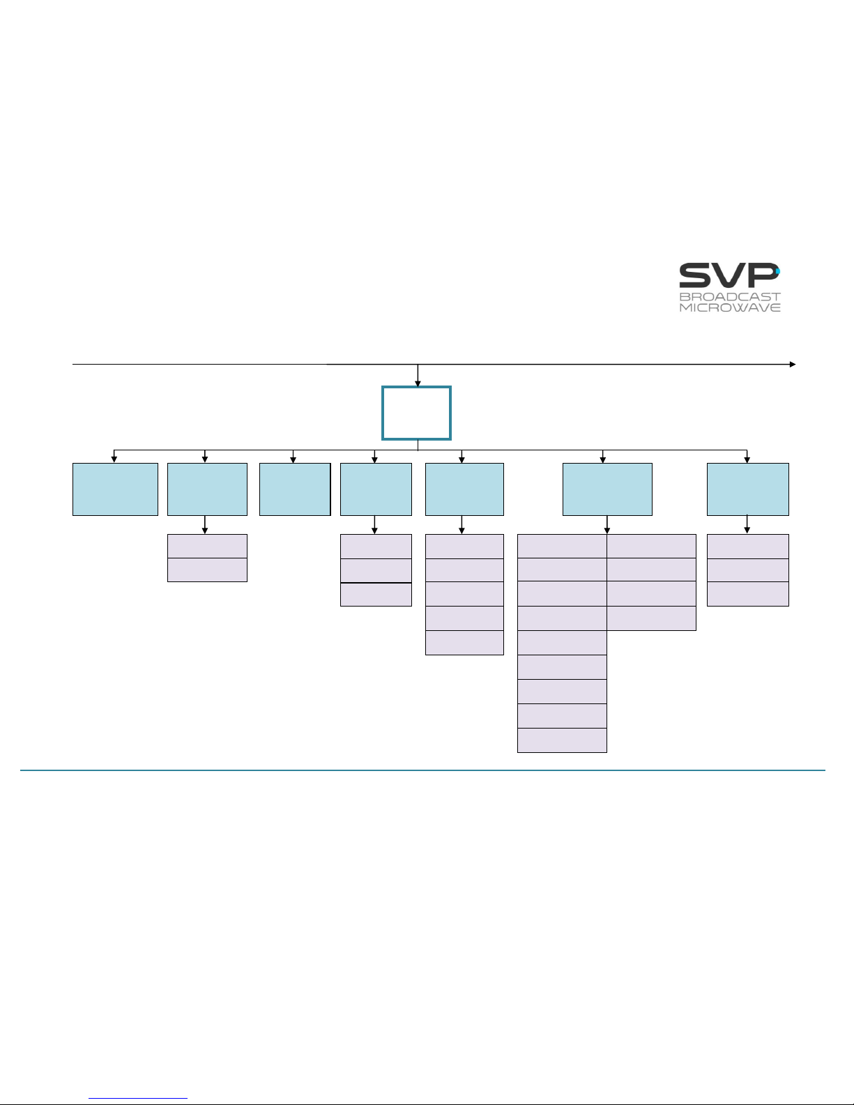
In the next page it is shown a scheme that specifies the different menu
options available.
18
HDE-70 H.264 – 4:2:2 – 10 bits Decoder
MANUAL V6.9
continued
HDE-70 MENU STRUCTURE
Local IP
Config.
Adr
Fec
Port
Output Delay
TP per IP
Status
Protocol
Packet Size
BitRate
PCR
ASI
IP Mode
Video
Format
Encoding
System
Audio
Status
Data
Input
Select
Decoder
MAIN SCREEN
Received signal type, Bitrate, Video codification, Output video signal format,
Profile, Delay, Audio and Data status, Number of cuts.
First Service
Manual
Service
User
GPS
Profile
Channel 1
Channel 2
Delay
Video
Codification
DID
PID Config
GenLock
Group
19
HDE-70 H.264 – 4:2:2 – 10 bits Decoder
MANUAL V6.9
continued
continued
BISS-1
BISS-E
Local IP
Config
Time to Live
Protocol
TP per IP
FEC
Dest IP & Port
CA-BISS
IP
Output
Decoder
Frame
Error
Frame
Without
Signal
Autotracking
Parabolic
Sector
Omni
IP/ASI
Output
20
HDE-70 H.264 – 4:2:2 – 10 bits Decoder
MANUAL V6.9
Unit
Alarms
Monitor
Webserver &
SNMP
Miscellaneous
Temperature
Logbook
Voltage
Locl
Mask
Gate
Firmware
Audio
Monitor
Video
Monitor
Audio Volume
Audio Speaker
Keyboard Beep
Night Mode
Alarm Beep
Clock
Location Labels
VoIP MAC
Network MAC
QuickSet Protocol
Distance Units
Speed Units
Timeout Reset
S/N
Current Version
Update Firmware
Restore Default
continued
Admin Pass
User Pass
Keyboard Lock
21
HDE-70 H.264 – 4:2:2 – 10 bits Decoder
MANUAL V6.9
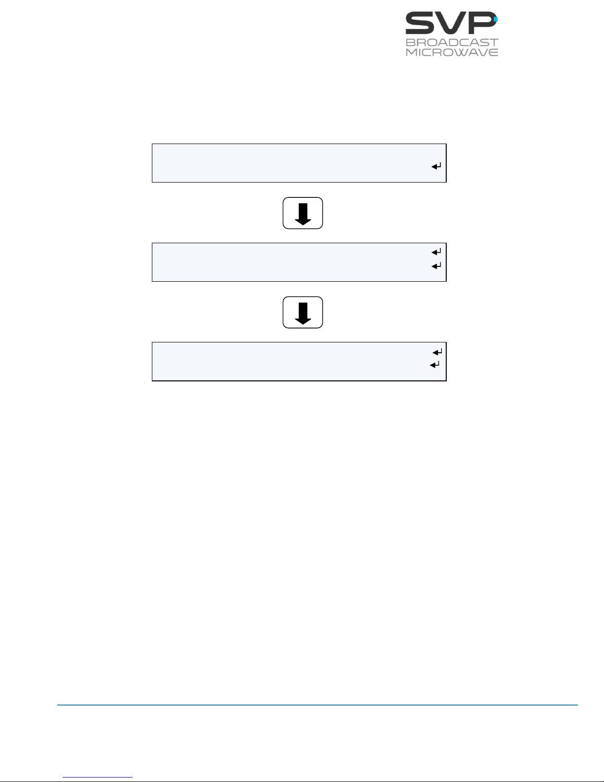
3.7.1 Menu Navigation
This section contains a detailed description of each parameter that can be
configured in the HDE-70 decoder via the MENU.
To enter the MENU, press the cross button in case of being in the main
screen or in any submenu.
To select a parameter or a submenu use Up, Down arrow buttons. Once
selected, press the OK button to access to a submenu or to edit a
parameter. To exit a submenu or a parameter, press the cross button.
Figure means that to have access to the right image that button
must be pushed.
Symbols <> mean that the parameter can be modified in the same screen
with the right and left keys.
Symbol means that pushing the OK button allows entering to the options
of the submenu.
Different types of parameters are available:
- Eligible: When the user can choose between predetermined
states. (They usually have the symbol <> near to them)
- Editable: When the user must enter a value in that option. (They
usually have the symbol near them). So as to save the
introduced value, the OK button must be pressed.
- Reading: When the value of that parameter is a monitored
parameter that can’t be changed.
Next, the different menus and submenus with the options and the different
parameters available are shown. Also, in each figure, example parameters
are shown.
22
HDE-70 H.264 – 4:2:2 – 10 bits Decoder
MANUAL V6.9
3.7.2 Menu Structure
The following menu screen can be accessed, by pressing the cross key from
the main screen.
Figure 3.13 Setup Menu
Input Select – All the parameters related to the decoded signal/s can be
modified here as well as the selection of the input type.
Decoder: All video, audio and data decoding parameters are accessible
here.
Autotracking – All the options and parameters related to the autotracking
configuration are shown in this option.
CA-BISS: The keys and the BISS mode can be configured in this option.
IP Output: Configuration parameters of the output signals are set in this
option.
Unit: Parameters related to the Web Server, UART and other internal
options of the receiver are configured here as well as other characteristics
owned to the HDE-70 decoder.
01 Input: ASI >
02 Decoder: PROGRAM 001
03 Autotracking: Parabolic >
04 CA BISS: BISS 1 >
05 IP Output: Enable <
06 Unit
23
HDE-70 H.264 – 4:2:2 – 10 bits Decoder
MANUAL V6.9
3.7.2.1 Input Select Menu
By using the Up, Down arrow keys, select the Input Select option and
press the OK key. Two inputs can be selected:
- ASI
- IP
3.7.2.1.1 ASI
By using the right and left arrow keys, select the ASI Input option.
Figure 3.14 ASI Input Screen
Then press the Cross button and these ASI options will appear in the main
screen:
Figure 3.15 ASI Input Screen
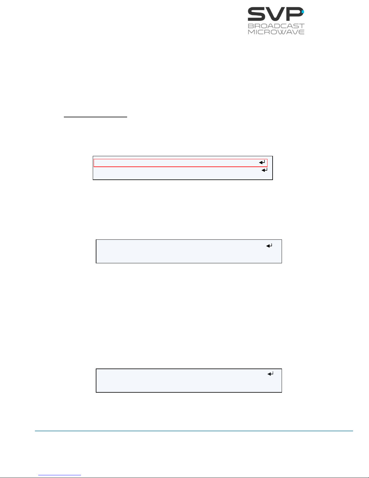
Pressing the OK button in the main screen, and having the Manual Service
option selected in the Decoder menu (this option is explained in Section
3.7.2.2.1), the user can access to the different services available and see
the name and number of each service.
Figure 3.16 Number and name of the services
If the user wants to change the service, select the desired service of the list
and press the OK button. This message will appear in the screen:
Input: ASI <>
Decoder: PROGRAM 001
ASI: 9.9Mb H.264 576/50i 420/S AAD
(06 services) PROGRAM 001
Received Signal Type
Bitrate
Video
Codification
Output Video
Signal Format
Profile
Delay
Audio Status
Data Status
Name of the selected
service
Number of
services
> (00001) PROGRAM 001 (Decoding…)
(00002) PROGRAM 002
Number of
the service
Name of the
service

24
HDE-70 H.264 – 4:2:2 – 10 bits Decoder
MANUAL V6.9
Figure 3.17 Change the service
Then, press the OK button again to change the desired service or the cross
button not to change it.
Change the service?
OK: Yes / X: No
25
HDE-70 H.264 – 4:2:2 – 10 bits Decoder
MANUAL V6.9
3.7.2.1.2 IP
By using the right and left arrow keys, select the IP Input option.
Figure 3.18 IP Input Screen
Then press the Cross button and these IP options will appear in the main
screen:
Figure 3.19 Main screen 1 IP
Pressing the OK button in the main screen, and having the Manual Service
option selected in the Decoder menu (this option is explained in Section
3.7.2.2.1), the user can access to the different services available and see
the name and number of each service.
Figure 3.20 Number and name of the services
If the user wants to change the service, select the desired service of the list
and press the OK button. This message will appear in the screen:
Figure 3.21 Change the service
Then, press the OK button again to change the desired service or the cross
button not to change it.
Input: IP <>
Decoder: PROGRAM 001
IP: 7.8Mb H.264 576/50i 420/S AAD
(06 services) PROGRAM 001
Received Signal Type
Bitrate
Audio/Video
Codification
Output Video
Signal Format
Decoder
Profile
Delay
Audio Status
Data Status
Number of
services
Name of the
Selected service
> (00001) PROGRAM 001 (Decoding…)
(00002) PROGRAM 002
Number of
the service
Name of the
service
Change the service?
OK: Yes / X: No
26
HDE-70 H.264 – 4:2:2 – 10 bits Decoder
MANUAL V6.9
To configure the different parameters related to the IP Input option, select
IP Input option and press the OK button.
Figure 3.22 IP Input Select Menu
InpIP Local IP Config
InpIP Adr: Unicast >
InpIP Fec: Disable >
InpIP Port: 5600
InpIP Output Delay: 128 [1..9942]ms
InpIP TP per IP: 1
InpIP Status: Channel ENABLE
InpIP Protocol: UDP
InpIP Packet Size: 188
InpIP BitRate: 0.00Mb
InpIP PCR: No Present

27
HDE-70 H.264 – 4:2:2 – 10 bits Decoder
MANUAL V6.9
Line nº
Function
1
InpIP Local IP Config:
So as to configure the network parameters, press the OK button.
(editable parameters)
The available options are:
Local:
So as to establish the Local IP address, press the OK button and
then, with the UP, Down buttons change the value. If the user
wants to change from one character to another, press the Right,
Left buttons. So as to save the introduced value, press the OK
button. If this IP is the same as the IP for remote control
(Webserver / SNMP), the device will show a warning message.
Mask:
In this field the Subnet Mask address must be specified. So as to
establish the Subnet Mask address, press the OK button and
then, with the UP, Down buttons change the number value. If
the user wants to change from one character to another, press
the Right, Left buttons. So as to save the introduced value, press
the OK button.
Gateway:
In this field the Gateway address must be specified. So as to
establish the Gateway address, press the OK button and then,
with the UP, Down buttons change the value. If the user wants
to change from one character to another, press the Right, Left
buttons. So as to save the introduced value, press the OK
button.
2
InpIP Adr:
So as to select the short of address from which IP information is
received, press Right, Left buttons. (eligible parameters)
The available options are:
Unicast:
In case it is wanted to receive the signal from any single IP
address to this device, unicast option must be chosen.
Multicast:
In case the signal is received from a multicast address, that
multicast address must be configured in this field. So as to enter
the multicast address, press the OK button so as to be able to
configure the multicast address. (editable parameter)

28
HDE-70 H.264 – 4:2:2 – 10 bits Decoder
MANUAL V6.9
3
InpIP Fec:
To select if FEC is enabled or disabled in the received signal press
Right, Left buttons. (eligible parameter)
The available options are:
Enable Col: Row: (The IP Forward Error Correction is
composed by a number of FEC columns and rows. In this field it
is shown the number of FEC columns and rows of the received
signal) (reading parameter)
Disable
4
InpIP Port:
This field must be filled in with the port number through which is
going to receive the signal. So as to edit this parameter, press the
OK button and then, select the desired port with the Up, Down, or
Right, Left buttons. So as to save the introduced value, press the OK
button. (editable parameter)
5
InpIP Output Delay [1..9942]ms:
Delay from IP input to ASI output which is the delay between the
obtaining of the IP input and the delivery to the decoder and to the
ASI output. So as to edit this parameter, press the OK button and
then, select the desired port with the Up, Down and Right, Left
buttons. So as to save the introduced value, press the OK button.
(editable parameter)
6
InpIP TP per IP:
This field displays the number of TS packets per IP packet. (reading
parameter)
7
InpIP Status:
This field displays the status of the IP input. (reading parameter)
8
InpIP Protocol:
This field displays the protocol used for the communication. (reading
parameter)
The possible options are:
UDP
RTP

29
HDE-70 H.264 – 4:2:2 – 10 bits Decoder
MANUAL V6.9
9
InpIP Packet Size:
This field shows the size in bytes (188 or 204 bytes) of the IP
received packets. (reading parameter)
The available values are:
Channel is enabled
Channel is disabled
Channel is enabled but there is a problem with the processing of
the received IP stream.
10
InpIP BitRate:
This field displays the bitrate of the received signal. (reading
parameter)
11
InpIP PCR:
Program Clock Reference. To enable a decoder to present
synchronized content, such as audio tracks matching the associated
video, at least once each 100 ms Program Clock Reference, or PCR
packets are. This parameter indicates if PCRs are found in incoming
TS. (reading parameter)
Table 3.4 IP Input Select menu option
30
HDE-70 H.264 – 4:2:2 – 10 bits Decoder
MANUAL V6.9
3.7.2.2 Decoder Menu
By using the Up, Down arrow keys, select the Decoder option and press
the OK key.
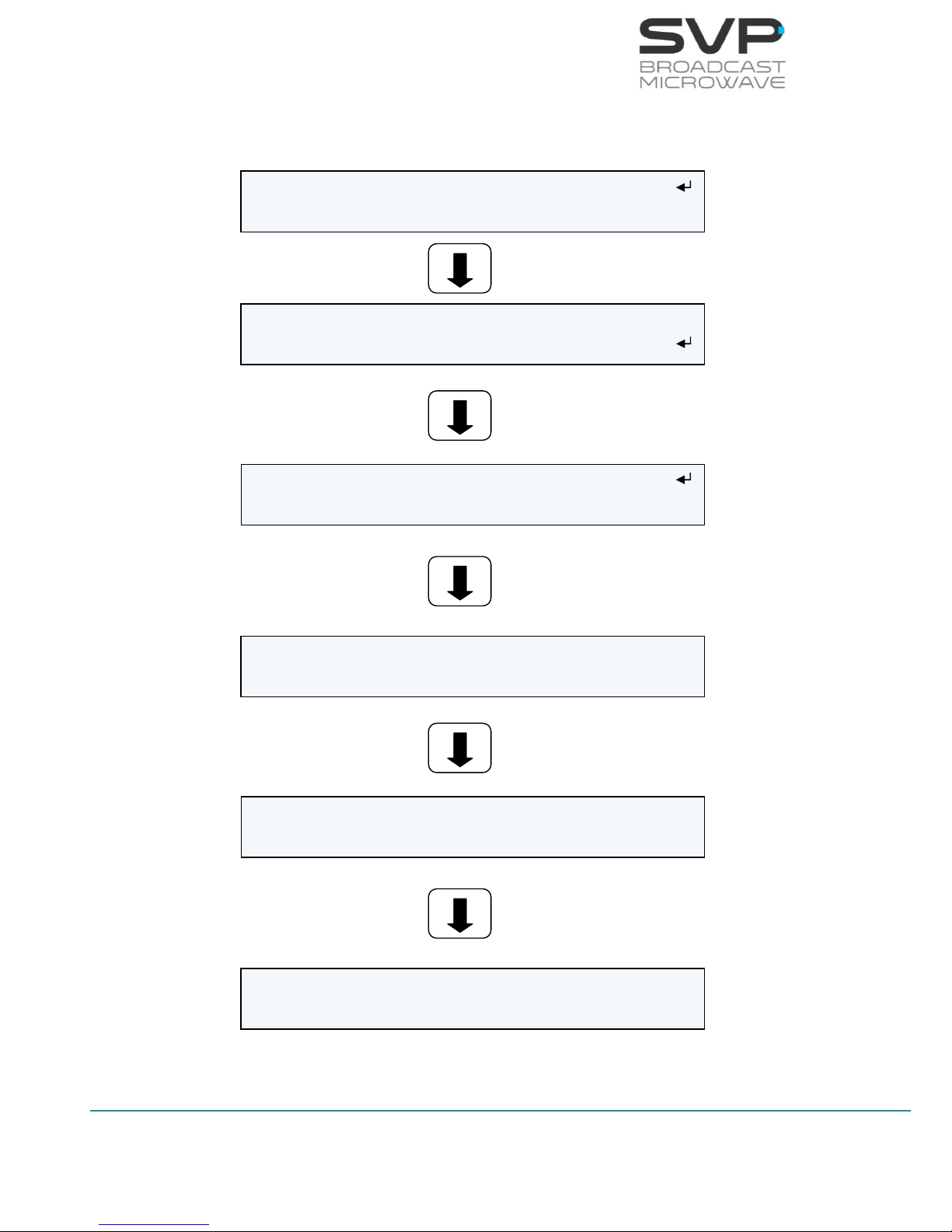
Figure 3.23 Decoder Menu
Decoder First Service: PROGRAM 001 >
Decoder Video Format: Auto (720/50p) >
Decoder Encoding System: 420/S [H.264]
Decoder Audio Status: CH1:256Kb CH2:256Kb
Decoder Data: 9600 NONE 1 [USER] <>
Decoder GenLock: Ref Lost Offset: 0pix
Decoder Frame Error: Freeze <
DecoderFrame Without Signal: Freeze >

31
HDE-70 H.264 – 4:2:2 – 10 bits Decoder
MANUAL V6.9
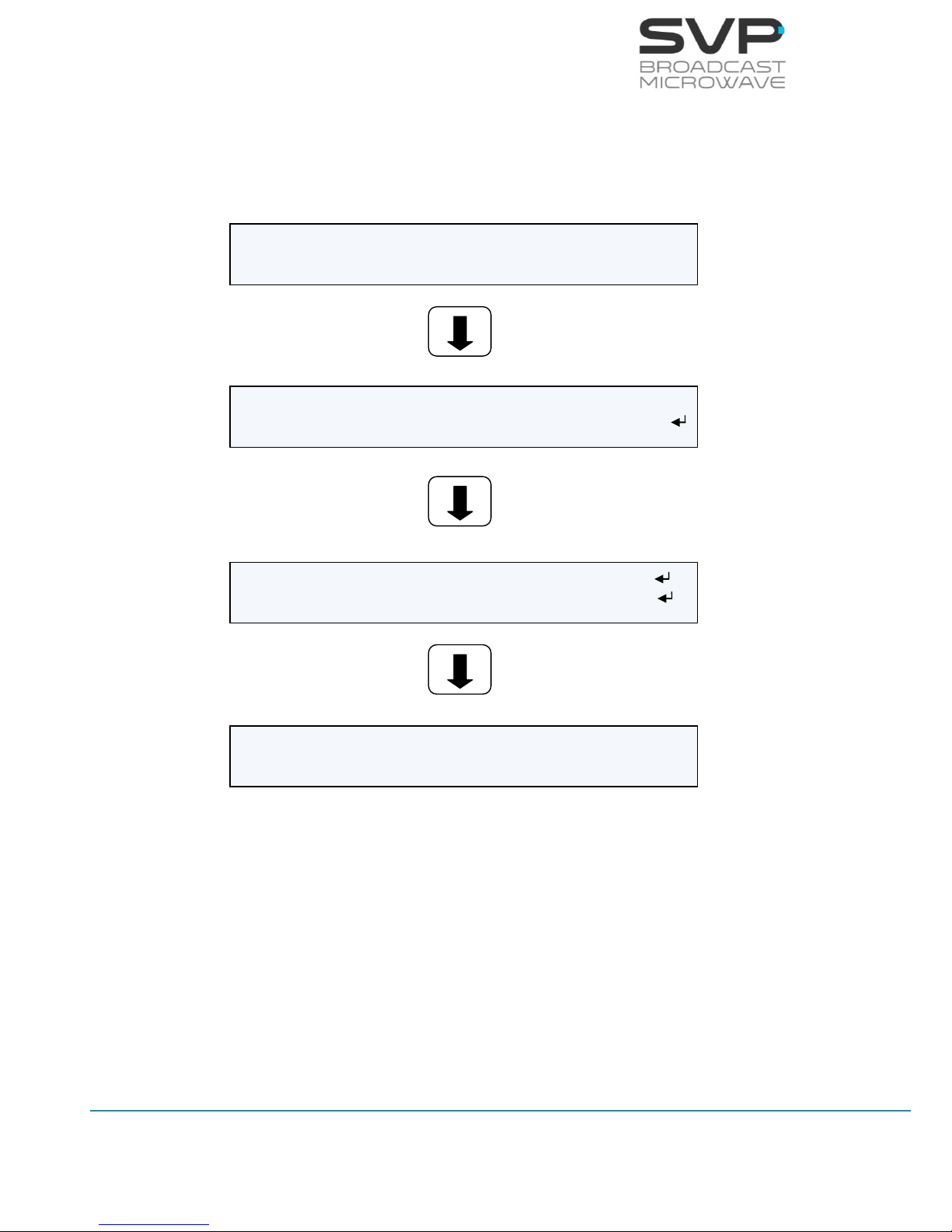
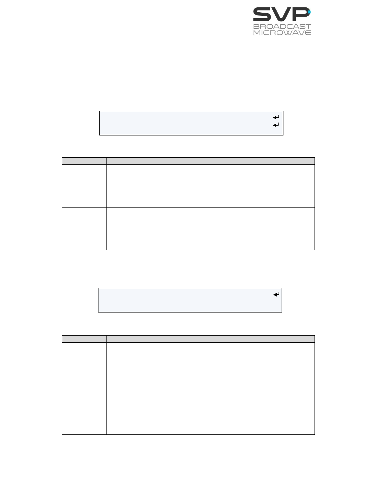
3.7.2.2.1 Mode Screen
In this field, the mode for the decoding process is selected. Use Right, Left
arrows buttons so as to select the appropriate option. (eligible parameters).
The available options are:
First Service Mode
If First Service option is selected, the first available service will be
shown.
Figure 3.24 Decoder First Service Mode Screen
Manual Mode
If Manual mode is selected, then, the user can select a service from
the list by clicking the OK button.
If the OK button is pressed, the user can access to the different
services available and see the name and number of each service. The
selected service is the one which has the Decoding word on the right.
Figure 3.25 Decoder Manual Mode Screen
If it is wanted to change the service, select the desired service of the
list and press the OK button. This message will appear in the screen:
Figure 3.26 Change the service
Then, press the OK button again to change the service or the cross
button not to change it.
Decoder First Service: PROGRAM 001 >
Decoder Video Format: Auto (720p/50) >
Decoder Manual Service: (06) PROGRAM 001 <>
Decoder Video Format: Auto >
(00001) PROGRAM 001 (Decoding…)
(00002) PROGRAM 002
Change the service?
OK: Yes / X: No
32
HDE-70 H.264 – 4:2:2 – 10 bits Decoder
MANUAL V6.9
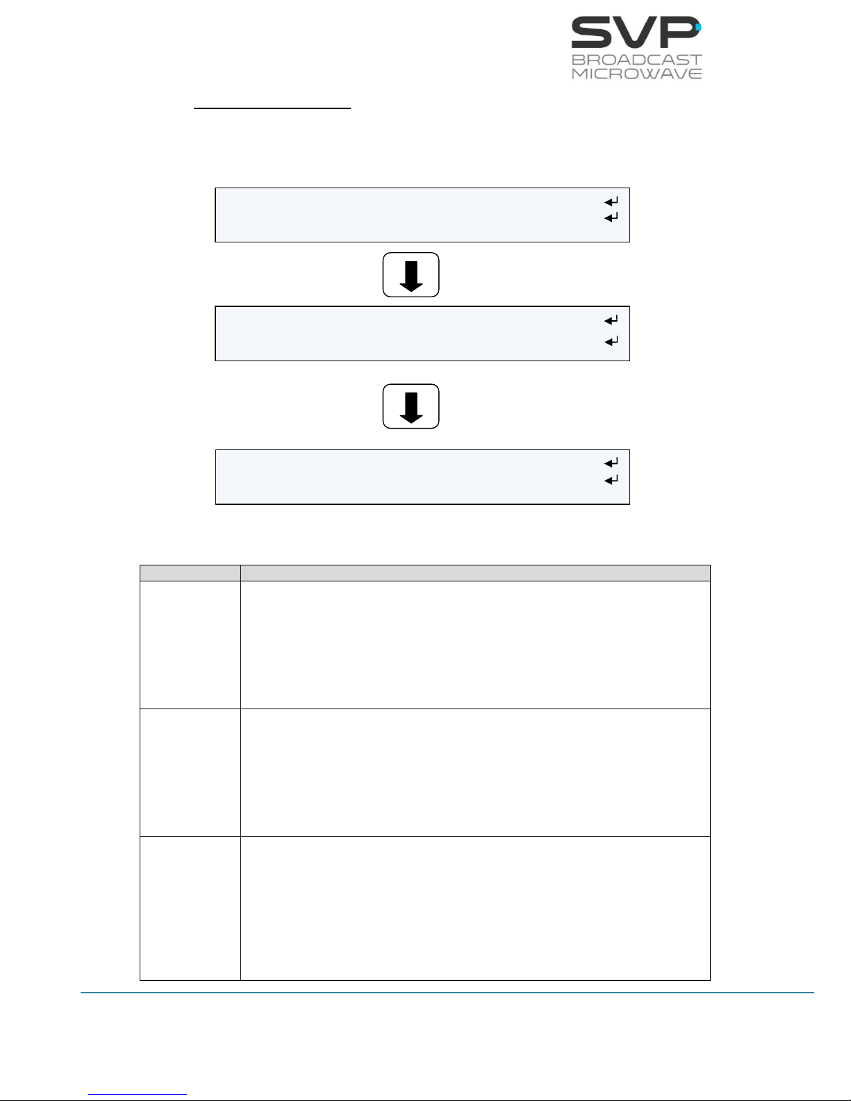
PID Selection Mode
Selecting the PID Selection option and pressing the OK button, the
user is able to configure the parameters shown below.
Figure 3.27 Decoder PID Selection Mode Screen
Line nº
Function
1
Video PID:
Here the video packet identifier must be entered. So as to change
its value first, press the OK button and then, with the UP, Down
arrows select the desired number. So as to save the introduced
value the OK button must be pressed again. (editable parameter)
2
Audio1 PID:
Here the audio1 packet identifier must be entered. So as to change
its value first, press the OK button and then, with the UP, Down
arrows select the desired number. So as to save the introduced
value the OK button must be pressed again. (editable parameter)
3
Audio2 PID:
Here the audio2 packet identifier must be entered. So as to change
its value first, press the OK button and then, with the UP, Down
arrows select the desired number. So as to save the introduced
value the OK button must be pressed again. (editable parameter)
Decoder Manual Video PID: 236
Decoder Manual Audio1 PID: 247
Decoder Manual Audio2 PID: 259
Decoder Manual Data PID: 248
Decoder Manual PMT PID: 231
Decoder Manual PCR PID: 278

33
HDE-70 H.264 – 4:2:2 – 10 bits Decoder
MANUAL V6.9
4
Data PID:
Here the data packet identifier must be entered. So as to change its
value first, press the OK button and then, with the UP, Down arrows
select the desired number. So as to save the introduced value the
OK button must be pressed again. (editable parameter)
5
PMT PID:
Here the program map tables packet identifier must be entered. So
as to change its value first, press the OK button and then, with the
UP, Down arrows select the desired number. So as to save the
introduced value the OK button must be pressed again. (editable
parameter)
6
PCR PID:
Here the program clock reference packet identifier must be entered.
So as to change its value first, press the OK button and then, with
the UP, Down arrows select the desired number. So as to save the
introduced value the OK button must be pressed again. (editable
parameter)
Table 3.5 PID Selection menu
3.7.2.2.2 Decoder Video Format Screen
This file allows the user to select the format of the received signal.
Figure 3.28 Decoder Video Format screen
There are many options available. Press the Right and Left button to select
the desired option:
Auto 1080/25p
480/60i 1080/60p
576/50i 1080/59p
720/60p 1080/50p
720/59p
720/50p
1080/60i
1080/59i
1080/50i
For MPEG-2 signals, the auto option is not available. It is necessary to
select one of the other options for the received signal.
Decoder First Service: PROGRAM 001 >
Decoder Video Format: Auto (720/50p) >

34
HDE-70 H.264 – 4:2:2 – 10 bits Decoder
MANUAL V6.9
3.7.2.2.3 Decoder Encoding System Screen
In this field, the next parameters are displayed in the screen.
Figure 3.29 Decoder Encoding System screen
Line nº
Function
1
Profile:
The profile of the received signal is displayed in this option.
(reading parameter)
The possible options are: 4:2:0 and 4:2:2.
Delay:
The delay of the received signal is displayed in this option.
(reading parameter)
The possible options are:
- Standard (S)
- Low Delay (L)
- Super Low Delay (SL)
Video Codification:
The video codification is shown in this option. (reading parameter)
The available options are: H.264 and MPEG-2.
In case the transmitter device is configured in Ultra Low
Delay, the receiver will indicate Super Low Delay. This
means that the receiver is not capable of distinguishing
between Super Low Delay and Ultra Low Delay.
Table 3.6 Decoder Encoding System menu
Decoder Encoding System: 420/S [H264]

35
HDE-70 H.264 – 4:2:2 – 10 bits Decoder
MANUAL V6.9
3.7.2.2.4 Decoder Audio Status Screen
In order to access to the decoder audio screen, the OK button must be
pressed. The parameters that appear in this screen are:
Figure 3.30 Decoder Audio Screen
Line nº
Function
1
Channel 1:
In this option, the bitrate of the audio channel1 signal and the audio
decoder type are shown: MPEG1 Layer 1 or 2. (reading parameters)
2
Channel 2:
In this option, the bitrate of the audio channel2 signal and the audio
decoder type are shown: MPEG1 Layer 1 or 2. (reading parameters)
3
DID:
Selects the audio group or DID in which the 4 audio channels are
going to be embedded in the SDI output signal. So as to select the
desired group, press the Right, Left buttons. (eligible parameters)
Table 3.7 Decoder Audio Status menu
Decoder Audio DID: Group1(767)
Decoder Audio Channel 1: 192Kb / MPEG-1
Decoder Audio Channel 2: 128Kb / MPEG-1

36
HDE-70 H.264 – 4:2:2 – 10 bits Decoder
MANUAL V6.9
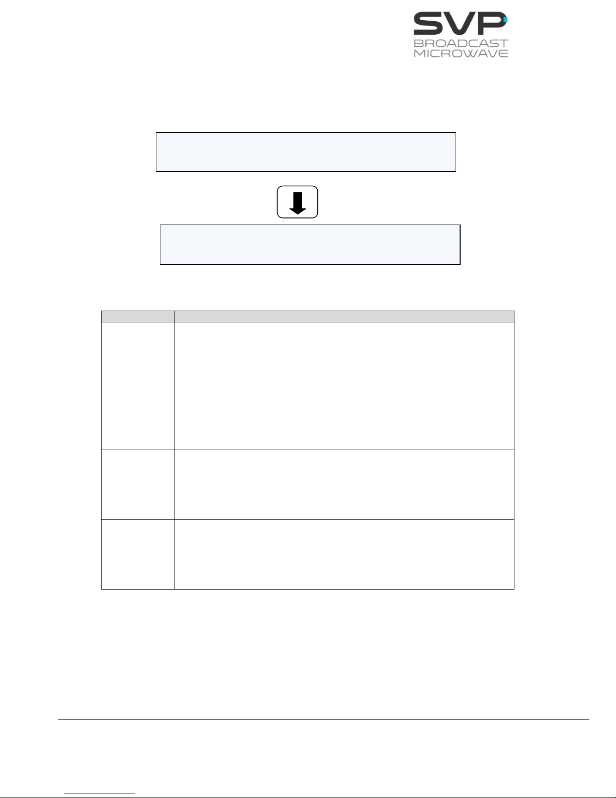
3.7.2.2.5 Decoder Data Screen
In this field, the sort of data that is going to be decoded must be selected.
The available options are:
User Screen
If this option is selected, it is possible to configure the next parameters
of the RS-232 port throughout the received data that is going to be
extracted.
Figure 3.31 Decoder User Screen
Line nº
Function
1
Baud Rate:
Select the baudrate at which the data is going to be extracted.
(Baudrate options are: 2400, 4800, 9600, 19200, 38400, 57600,
78600, 115200) (eligible parameters)
2
Parity:
The parity options are None, Even, Odd. (eligible parameters)
3
Stop Bits:
The options are 1 or 2. (eligible parameter)
Table 3.8 Decoder User menu
Decoder Data Stop Bits: 1 >
Decoder Data 9600 NONE 1 [USER] <>
Decoder Data Baud Rate: 9600 <>
Decoder Data Parity: NONE >

37
HDE-70 H.264 – 4:2:2 – 10 bits Decoder
MANUAL V6.9
GPS Screen
Below, it is explained the GPS screen and the meanings of the parameters
related to the GPS.
Once user has accessed to the GPS screen, two options to choose will
appear:
Transmitter GPS Information
Local GPS Information
First, press the OK button to access to Transmitter GPS Information screen.
Figure 3.32 Decoder GPS screen
There are different options to select and configure:
Figure 3.33 Transmitter GPS Information screen
Line nº
Function
1
TX Distance:
In this option, different parameters are shown (reading
parameters):
- Distance between transmitter & receiver (km)
- Direction from transmitter to receiver (degrees)
- Height difference (m)
Transmitter GPS Information
Local GPS Information
TX Distance: 4819.9km 175º ΔH:-147m
TX Position: S-- 0kn ---º 0m
TX Position: #--º--.---´ #--º--.---´
Distance between
transmitter and
receiver
Direction from
transmitter to
receiver
Height difference
Number of satellites
Speed of the
transmitter
Direction of the
transmitter
Height of the
transmitter
Latitude and Longitude of the
transmitter

38
HDE-70 H.264 – 4:2:2 – 10 bits Decoder
MANUAL V6.9
2
TX Position:
In this option, different parameters are shown (reading
parameters):
Number of satellites
Speed of the transmitter (kn)
Direction of the transmitter (degrees)
Height of the transmitter (m)
3
TX Position:
In this option, different parameters are shown (reading
parameters):
Latitude of the transmitter
Longitude of the transmitter
Table 3.9 Transmitter GPS Information menu
Secondly, press the OK button to access to Local GPS Information screen.
Then, there are different options to select and configure:
Figure 3.34 Local GPS Information screen
Line nº
Function
1
Local Manual:
In this file the user can set the coordinates of the transmitter.
(editable parameters)
2
Local Altitude:
In this file the user can set the height and the number of satellites.
(editable parameters)
Table 3.10 Local GPS Information menu
Transmitter GPS Information
Local GPS Information
Local Manual: N43º10.442´ W002º38.238’
Local Alt: 147m S:--
Coordinates
Number of satellites
Height

39
HDE-70 H.264 – 4:2:2 – 10 bits Decoder
MANUAL V6.9
3.7.2.2.6 Decoder GenLock Screen
This device has an external Genlock reference input in order to lock all the
video outputs to it. (reading parameter)
Figure 3.35 Decoder GenLock screen
The available options are:
Reference lost: The device does not detect the genlock signal.
Reference unlocked: The device detects the genlock signal but it is not
capable of synchronizing to that signal.
Reference locked: The device detects the genlock signal and is capable
of synchronizing to that signal.
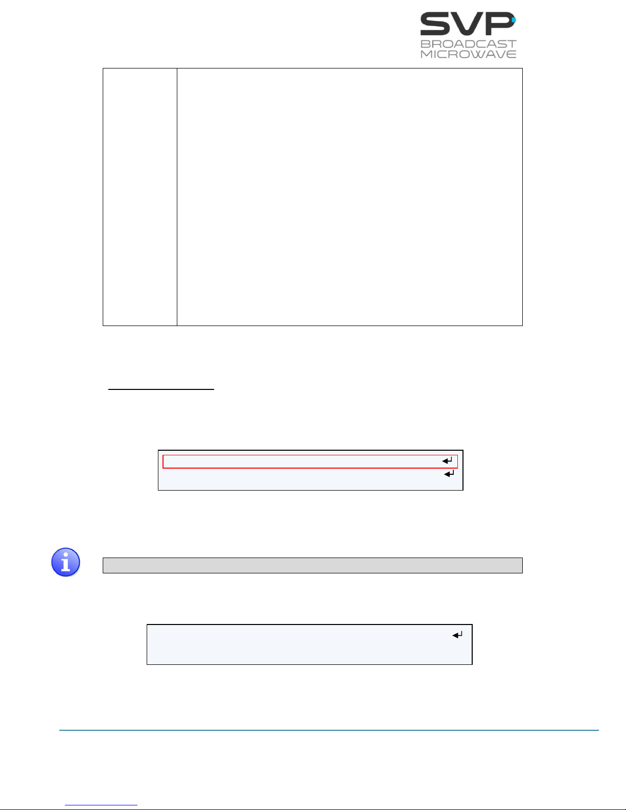
3.7.2.2.7 Decoder Frame Error Screen
In this file, if there is a frame error, the broken image is shown in the
screen to advice that there has been an error (elegible parameter).
Figure 3.36 Decoder Frame Error screen
There are two options available. Press the Right and Left button to select
the desired option:
Continue with errors: If there is an error, the image is shown with
errors in the screen.
Freeze: If there is an error, the image is frozen in the screen.
Decoder GenLock: Ref Lost Offset: 0pix
Decoder Frame Error: Continue with errors >
Decoder GenLock: Ref Lost Offset: 0pix
Decoder Frame Error: Freeze <

40
HDE-70 H.264 – 4:2:2 – 10 bits Decoder
MANUAL V6.9
3.7.2.2.8 Decoder Frame Without Signal Screen
In this option, if there is an error, the last image is frozen in the screen until
the signal works again (elegible parameter).
Figure 3.37 Decoder Frame Freeze screen
There are two options available. Press the Right and Left button to select
the desired option:
Freeze: The last image is frozen in the screen until the signal works
again.
Colour (10 sec): After 10 seconds, if there is not RF signal, the screen
becomes red. However, after 10 seconds, if there is not video signal, the
screen becomes blue.
Decoder Frame Without Signal: Freeze >
41
HDE-70 H.264 – 4:2:2 – 10 bits Decoder
MANUAL V6.9
3.7.2.3 Autotracking Menu
In this section it is explained how to configure the autotracking with
different types of antenna. The possible options are:
Parabolic
Sector
Omni
Parabolic antenna
Next, it is explained how to configure the autotracking with a parabolic
antenna and the different parameters related to it. Press the OK button so
as to enter to the configuration menu.
Figure 3.38 Parabolic Antenna option
Once the user is inside the parabolic section, there are four possible options
(eligible with the Right, Left keys) which are detailed below:
I. Auto
Figure 3.39 Parabolic Autotracking (Auto)
When the Auto option is selected, it means that the parabolic
antenna is aimed automatically to the transmitter device throughout
the GPS coordinates of the transmitter and the receiver device. If
the OK button is selected in this option, the parameters related to
the transmitter GPS information (TX Distance and TX Position) and
the local GPS information (Local Manual and Local Altitude) are
shown.
II. Manual
Figure 3.40 Parabolic Autotracking (Manual)
DVB-T Autotracking: Parabolic >
CA BISS: BISS-1 >
H: 061º V: 09º Δd:-------- ΔH:-- Manual >
L1 [ ]:-- C/N [ ]:-
H: 061º V: 09º Δd: -------- ΔH:-- Auto <>
L1 [ ]:-- C/N [ ]:-
42
HDE-70 H.264 – 4:2:2 – 10 bits Decoder
MANUAL V6.9
If the Manual option is selected, then, by pressing the OK button the
user can select manually the position of the parabolic antenna. So
as to change the azimuth (H) position of the antenna, press the
Right, Left buttons. So as to change the elevation (V) position of the
antenna, press the Up, Down buttons.
III. Fold
Figure 3.41 Parabolic Autotracking (Fold)
Line nº
Function
1
Fold Tilt:
In this file, the number of degrees that are needed to fold the
antenna is displayed. (editable parameter)
2
Fold the antenna:
In this file, it is necessary to choose if the user wants to fold or not
the antenna. (editable parameter)
Table 3.11 Fold menu
IV. Config
Figure 3.42 Parabolic Autotracking (Config)
Line nº
Function
1
In this file, the user is allowed to configure the polarization, offset
and the source of the GPS signal.
Polarization:
The polarization of the antenna is selected. (eligible
parameter)
The available options are:
None
Vertical
Config <
POL: None H.Offset:000 Remote GPS:AUTO
Fold Tilt: -30º Fold <>
Fold the antenna
43
HDE-70 H.264 – 4:2:2 – 10 bits Decoder
MANUAL V6.9
Horizontal
RHCP
LHCP
H. Offset
The desired offset of the antenna can be selected pressing
the Up, Down buttons. (editable parameter)
Remote GPS
In this field, the source of the GPS signal must be selected.
(eligible parameter)
The available options are:
AUTO (The available option is selected automatically.
If both options are available, UHF will be selected)
HDT-02 (If the GPS comes from the HDT-02
transmitter)
UHF (If the GPS signal comes from the UHF radio)
Table 3.12 Config menu
Sectorial Antenna
Next, it is explained how to configure the autotracking with a sectorial
antenna.
Figure 3.43 Sectorial Antenna option
Once the user is inside the sectorial option, there are three possible options
(eligible with the Right, Left keys) which are detailed below:
Value T means the top antenna.
I. Auto
Figure 3.44 Sector Autotracking (Auto)
DVB-T Autotracking: Sector <>
CA BISS: BISS-1 >
1 2 3 [4] 5 T Δd: -------- Auto<>
L [ ]:-- C/N [ ]:-

44
HDE-70 H.264 – 4:2:2 – 10 bits Decoder
MANUAL V6.9
When the Auto option is selected, it means that the sector antenna
is automatically selected. The selected sector is the one which is
marked with the square brackets.
If the OK button is selected in this option, the parameters related to
the transmitter GPS information (TX Distance and TX Position) and
the local GPS information (Local Manual and Local Altitude) are
shown.
II. Manual
Figure 3.45 Sector Autotracking (Manual)
If the Manual option is selected then, by pressing the OK button the
user can select manually the sector antenna from which it is wanted
to receive the signal.
III. Config
Pressing the OK button when the Config option is selected, the user
is allowed to configure the number of the sectorial antennas, the
degrees of the sectors and if a top antenna is included.
Figure 3.46 Sector Autotracking (Config)
Using the Up, Down keys the user can change the value of each
parameter and with the Right, Left buttons the user can select the
value to be modified. So as to save the values, the OK button must
be pressed.
Omni antenna
In this option, the autotracking is configured with an omnidirectional
antenna and the different parameters related to it.
Figure 3.47 Omni Antenna option
1 2 3 [4] 5 T Config <
Nr. antennas: 6 Deg: 75º UP:Yes Rem.GPS:AUTO
1 2 3 [4] 5 T Manual <>
L [ ]:-- C/N [ ]:-
DVB-T Autotracking: Omni <
CA BISS: BISS-1 >
45
HDE-70 H.264 – 4:2:2 – 10 bits Decoder
MANUAL V6.9
3.7.2.4 CA-BISS Menu
By using the Up, Down arrow keys, select the CA-BISS option and press
the OK key.
Figure 3.48 CA-BISS Menu
Line nº
Function
1
Mode:
So as to choose the desired encryption, press the Right, Left
keys.(eligible parameter)
The available options are:
BISS-1 (Uses an unencrypted key for the BISS key)
BISS-E (Uses an encrypted key)
2
SsWord:
In this field, the SsWord password must be introduced, which is
valid for BISS-1 and BISS-E encryption. (editable parameter)
3
UserID:
In this field, the UserID password must be introduced, which is valid
only for BISS-E encryption. (editable parameter)
Table 3.13 CA-BISS menu options
CA UserID: **********
CA Mode: BISS-E <
CA SsWord: ************

46
HDE-70 H.264 – 4:2:2 – 10 bits Decoder
MANUAL V6.9
So as to introduce the key in the BISS-1 option, follow these steps:
1. Choose the BISS-1 option in the Mode field.
2. Go one field down (CA SsWord) and press the OK button so as to be
allowed to introduce the key.
3. With Left, Right buttons select one field and with UP, Down buttons
choose one value from 0 to 9 or A to F.
4. Press the OK button to set the key.
So as to introduce the key and the user id in the BISS-E option, follow
these steps:
1. Choose the BISS-E option in the Mode field.
2. Go one field down (CA SsWord) and press the OK button so as to be
allowed to introduce the key.
3. With Left and Right buttons select one field and with UP and Down
buttons choose one value from 0 to 9 or A to F.
4. Press the OK button to set the UserID.
5. Go another field down (CA UserID) and press the OK button so as to
be allowed to introduce the key.
6. With Left, Right buttons select one field and with UP, Down buttons
choose one value from 0 to 9 or A to F.
7. Press the OK button to set the key.
The receiver device is capable of distinguishing if the input signal is
encrypted or not and, because of this, the Not Encrypted option is not
available. If the input signal is not encrypted then, parameters related to
the BISS (SsWord and UserID) are not taken into account.
On the other hand, if the input signal is encrypted, the user must select the
same sort of encryption (BISS-1 or BISS-E) as the one selected in the
transmitter and the same keys used in the encryption step.

47
HDE-70 H.264 – 4:2:2 – 10 bits Decoder
MANUAL V6.9
3.7.2.5 IP Output Menu
By using the Up, Down arrow keys, select the IP Output option. This
output can be enabled or disabled pressing the right and left buttons.
Figure 3.49 IP Output
To configure the different parameters related to this option, select the
enable option and press the OK button.
Figure 3.50 Output Menu
Local IP Config
Dest IP & Port: 192.168.001.040:5678
Fec: Disable >
TP per IP: 7 [1..7] <
Protocol: UDP >
Time to Live: 80 [1..255]
IP/ASI Output: Always Descrambled >
CA-BISS: BISS-1 >
IP Output: Enable <

48
HDE-70 H.264 – 4:2:2 – 10 bits Decoder
MANUAL V6.9
Line nº
Function
1
Local IP Config:
In this field, different parameters related to the configuration of the
local network can be set.
The available parameters are:
Local:
IP address of the device which is going to send the information.
So as to change the IP address first press the OK button and
then, with the Up, Down keys select the desired number. So as
to change from one character to another, press Right, Left keys.
So as to save the value, press the OK button. (editable
parameters)
Mask:
Subnet address of the device which is going to send the
information. So as to change the Subnet Mask address first press
the OK button and then, with the Up, Down keys select the
desired number. So as to change from one character to another,
press Right, Left keys. So as to save the value, press the OK
button. (editable parameters)
Gateway:
Gateway address of the device which is going to send the
information. So as to change the Gateway address first press the
OK button and then, with the Up, Down keys select the desired
number. So as to change from one character to another, press
Right, Left keys. So as to save the value, press the OK button.
(editable parameters)
2
Dest IP & Port:
In this option, the IP address and the number of the port of the
device to which data is sent must be configured. In case it is wanted
to send data to a multicast address just enter the desired multicast
address. So as to change the IP address and the number of the port,
first press the OK button and then, with the Up, Down keys select
the desired number. So as to change from one character to another,
press Right, Left keys. So as to save the value, press the OK button.
(editable parameter)
3
Fec:
In this field the Forward Error Correction can be enabled or disabled.
In case it is enabled, the number of columns and rows can be
configured pushing firstly the OK button and then, with the Up,
Down arrows, the number of columns and rows wanted can be
selected. If FEC option is enabled then, the only protocol which can
be used is RTP. (eligible parameter and editable if enable option is
chosen)

49
HDE-70 H.264 – 4:2:2 – 10 bits Decoder
MANUAL V6.9
4
TP per IP:
In this field the number of Transport Stream packets per IP (from 1
to 7) can be configured. So as to select the desired value, press the
Right and Left buttons. (eligible parameter)
5
Protocol:
The type of protocol used for the communication can be RTP or UDP.
So as to select the desired protocol for the communication, use
Right and Left buttons. (eligible parameter)
6
Time to Live:
This field limits the lifetime of the data. The Time to Live value (from
1 to 255) means the number of routers that a packet can reach until
that packet is discarded. So as to configure this value, first press the
OK button and then, with the Up, Down, Right and Left buttons
select the desired value. So as to save the value, press the OK
button. (editable parameter)
7
IP/ASI Output:
In this field, the use of the BISS encryption in the IP and ASI
outputs of the receiver can be configured. (eligible parameter)
The available options are:
Standard:
In this option, if the transmitter’s signal is encrypted, there will
be encryption in the IP and ASI outputs of the receiver. If the
transmitter’s signal works without encryption, there will not be
encryption in the ASI and IP outputs of the receiver.
Always Descrambled:
In this option, the IP and ASI outputs of the receiver will always
be without encryption.
Table 3.14 Output menu options

50
HDE-70 H.264 – 4:2:2 – 10 bits Decoder
MANUAL V6.9
3.7.2.6 Unit
By using the Up, Down arrow keys, select the Unit option and press the OK
key.
Figure 3.51 Unit Menu
Unit Webserver & SNMP
Unit Miscellaneous
Unit Alarms
Unit Monitor
Unit Firmware
Unit Video Monitor Enable <
Unit Audio Monitor Audio 1 >

51
HDE-70 H.264 – 4:2:2 – 10 bits Decoder
MANUAL V6.9
3.7.2.6.1 Unit Video Monitor Screen
In this option, the video monitor can be configured.
Figure 3.52 Video Monitor Menu
In this field, the TFT video screen can be enabled or disabled. So as to
switch off the TFT video screen, select the Disable option with Right, Left
buttons. If it is wanted to switch on the TFT video screen, the enable option
must be selected. (eligible parameter)
The available options are:
Enable
Disable
3.7.2.6.2 Unit Audio Monitor Screen
In this field, the speakers and headphone audio outputs can be enabled,
disabled or configured.
The available options are Audio 1 and Audio 2. Each option has elegible
parameters to configure the audio monitor. So as to configure them, the OK
button must be pressed and these options will appear:
Figure 3.53 Audio Monitor Menu
Video Monitor Enable <
Audio Monitor Audio Volume 10 <>
Audio Monitor Audio Speaker Right <>
Audio Monitor Audio 1 >
OK

52
HDE-70 H.264 – 4:2:2 – 10 bits Decoder
MANUAL V6.9
Line nº
Function
1
Audio Volume:
Select the level of the audio output signal. The level range is from 0
to 15 where the higher one is the number 15 and the lower one is 0.
(elegible parameter)
2
Audio Speaker:
In this field, the mode of the audio output can be selected with the
Right, Left buttons. (eligible parameter)
The available options are:
None: Both of the audio outputs are disabled.
Left: Select this option to have the left channel of the
audio output enabled and the right one disabled.
Right: Select this option to have the right channel of the
audio output enabled and the left one disabled.
Right & Left: Select this option if it is wanted to have
both of the audio channels (right and left) enabled.
Table 3.15 Audio Monitor menu options
3.7.2.6.3 Unit Alarms Screen
Pressing the OK button, the alarms that are taking place can be seen in this
option.
Figure 3.54 Alarms Menu
In this option, different alarms which appear in the device are shown.
The different alarms that can appear in the receiver are:
- Input Signal Not Present
- No Video Present
- DC Voltage Low
- DC Voltage High
- High Temperature
1 INPUT SIGNAL NOT PRESENT
2 NO VIDEO PRESENT

53
HDE-70 H.264 – 4:2:2 – 10 bits Decoder
MANUAL V6.9
3.7.2.6.4 Unit Monitor Screen
In this field, several monitor parameters of the device are displayed.
Figure 3.55 Monitor Menu
In this screen several monitor parameters can be accessed:
Line nº
Function
1
Temperature:
In this option, the internal temperature of the device is shown. With
the Right, Left keys, the user can select if the temperature is shown
in ºC or in ºF. Also, the value which is between square brackets
means the speed of the fans (values from 0 to 3) where 0 means
that the fans are stopped and value 3 is the maximum speed.
(reading parameter)
2
Voltage:
In this option, the voltage of the device is shown. (reading
parameter)
3
Logbook:
Pressing the OK button allows the user to access to the Logbook
menu where the different events occurred are shown. (reading
parameter)
Table 3.16 Unit Monitor menu options
Unit Monitor Temperature +43.6ºC [0] >
Unit Monitor Voltage: 24.0 Volt
Unit Monitor Logbook

54
HDE-70 H.264 – 4:2:2 – 10 bits Decoder
MANUAL V6.9
3.7.2.6.4.1 Monitor LogBook
Figure 3.56 Monitor LogBook Menu
In this option, different actions in the device occurred since the last time
that the logbook was cleared are saved. The total number of logs that can
be saved are 4096. In case the user wants to clear all the LogBook, go to
the LogBook.Clear option and press the OK button. If the user wants to see
all the events that have occurred, go to the option LogBook.View and press
the OK button.
3.7.2.6.4.2 LogBook.View
Figure 3.57 LogBook.View Menu
In this screen, the different logs that have occurred during the operation of
the device are shown. There are displayed the time at which the event
occurred, the date of the event and a short description of that event.
LogBook Clear
LogBook View (23/4096)
0: 12:11:44 11/12/13 RF locked
1: 12:12:47 11/12/13 Decoding start
Number of logs saved
Number of logs shown
Time of the event
Date of the event
Description of the event

55
HDE-70 H.264 – 4:2:2 – 10 bits Decoder
MANUAL V6.9
3.7.2.6.5 Unit Webserver & SNMP Screen
In this field, different parameters related to the configuration of the
webserver are shown.
Figure 3.58 Webserver & SNMP Menu
The available parameters are:
Line nº
Function
1
Locl:
In this option the IP address of the device can be set in case it is
wanted to control the device remotely. So as to change the IP
address, first press the OK button and then, with the Up and Down
keys select the desired number. So as to change from one character
to another, press Right and Left keys. (editable parameter)
2
Mask:
Here it can be written the Subnet Mask address of the device. So as
to change the Subnet Mask address first press the OK button and
then, with the Up and Down keys select the desired number. So as
to change from one character to another, press Right and Left keys.
(editable parameter)
Locl: 192.168.001.110
Mask: 255.255.255.000
Gate: 192.168.001.001
Admin Pass: ********
Restore Def: >
User Pass: ********
Restore Def: >

56
HDE-70 H.264 – 4:2:2 – 10 bits Decoder
MANUAL V6.9
3
Gate:
In this option, the address of the Gateway must be written. So as to
change the Gateway address first press the OK button and then,
with the Up and Down keys select the desired number. So as to
change from one character to another, press Right and Left keys.
(editable parameter)
4
Admin Pass:
The administrator’s password is introduced. It is a list of 8 digits. It
can be set an own password or restore the default password
(00000000). (editable parameter)
5
User Pass:
In this option user’s password is introduced. It is a list of 8 digits. It
can be set an own password or restore the default password
(00000000). (editable parameter)
Table 3.17 Webserver & SNMP menu options
57
HDE-70 H.264 – 4:2:2 – 10 bits Decoder
MANUAL V6.9
3.7.2.6.6 Unit Miscellaneous Screen
In this field, several parameters related to the mode of operation of the
device can be configured.
Misc Keyboard Beep: OFF >
Misc Keyboard Lock: OFF >
Misc Night Mode: 0 >
Misc Alarm Beep: Disable >
Hour
Minute
Second
Day
Month
Year
Misc VoIP MAC: 00-14-F4-05-85-CA
Misc Network MAC 70-B3-D5-1A-C3-00
Misc QuickSet Protocol: PTCR-20 >
Misc Distance Units: Kilometers >
Misc Speed Units: Knots >
Misc Timeout Reset: 720 min
Misc Clock: h:m:s d/m/y
Misc Location Labels

58
HDE-70 H.264 – 4:2:2 – 10 bits Decoder
MANUAL V6.9
Figure 3.59 Miscellaneous Menu
The available options are:
Line nº
Function
1
Keyboard Beep:
If this option is OFF, then, when the user clicks any key of the
keyboard, there will be no sound. If the ON option is selected then,
a beep sound appears each time a key is pressed. So as to select
between ON and OFF options, press the Right, Left keys. (eligible
parameter)
2
Keyboard Lock:
If the On option is selected and then, the buttons of the equipment
remain for 5 minutes without being pressed, a message will appear
in the screen saying that the keyboard is locked. Pressing the cross
button, the keyboard can be unlocked. If the Off option is selected
there will be no messages in the screen.
The available options are:
On
Off
3
Night Mode:
There are four possible states for the night mode. If night mode is in
state 0 then the light in the screen will shine more than if it is in
state 1. If the state is three, then, the light in the screen will be the
lowest among the four possible states. (eligible parameter)
The available options are:
0
1
2
3
4
Alarm Beep:
If this option is enabled then a beep noise will sound each time that
an alarm occurs. (eligible parameter)
The available options are enable or disable.
Misc Timeout Reset: 720 min
Misc S/N: 660010911

59
HDE-70 H.264 – 4:2:2 – 10 bits Decoder
MANUAL V6.9
5
Clock:
In this field the date and the current hour are displayed and they
can also be configured pressing the OK button and changing the
values with Up, Down and Right, Left buttons. (reading and editable
parameter)
6
Location Labels:
In this field there can be configured several parameters such as the
place in which the device is located as well as the position of the
transmitter and the receiver device. (editable parameter)
7
VoIP MAC:
In this field the MAC address of the Video over IP card is displayed
(reading parameter)
8
Network MAC:
In this field the MAC address of the network is shown. (reading
parameter)
9
QuickSet Protocol:
In this field the MAC address of the network is shown. (reading
parameter)
10
Distance Units:
If miles is selected, then, all the distances will be in miles and the
same occurs if kilometers is selected. (elegible parameter)
The available options are:
Kilometers
Miles
11
Speed Units:
In this field, the desired parameter is selected to measure the
speed. There are three options available:
Knots
Km/h
Mph

60
HDE-70 H.264 – 4:2:2 – 10 bits Decoder
MANUAL V6.9
12
Timeout Reset:
In this field the time that the receiver could be without receiving
any signal is selected. After passing this time, the equipment is
reset. To disable this option, 0 value must be written.
13
S/N:
In this field the serial number of the device is shown (reading
parameter).
Table 3.18 Miscellaneous menu options
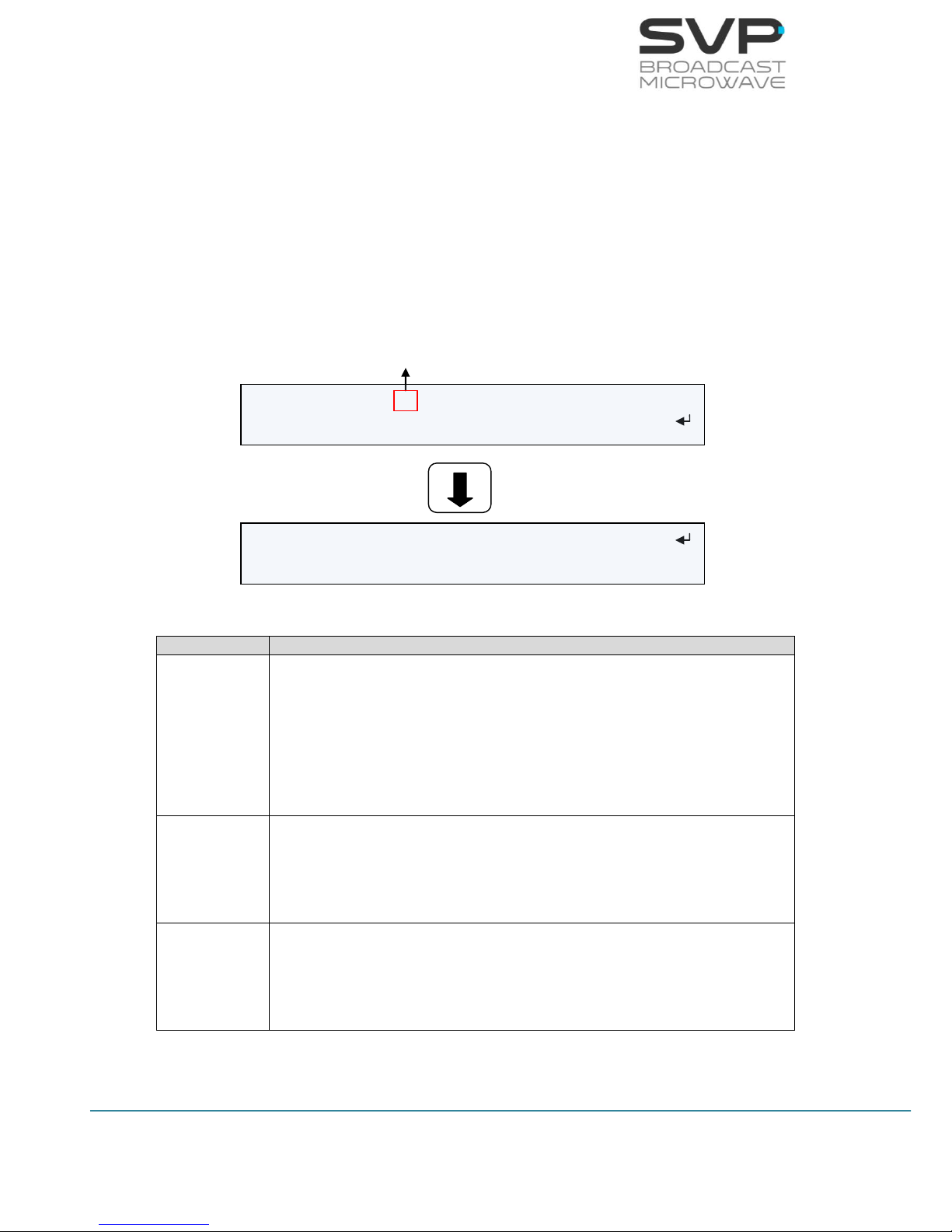
61
HDE-70 H.264 – 4:2:2 – 10 bits Decoder
MANUAL V6.9
3.7.2.6.7 Unit Firmware Screen
In this option, the firmware of the device can be updated with a USB device.
The steps to update the device are explained below.
This field shows three options:
Current Version
Update Firmware
Restore Default
Figure 3.60 Encoder Menu
Line nº
Function
1
Current Version:
In this field the number of the version installed in the device is
shown. The characters which describe the number of the version are
the one inside the red box shown in the figure above. The rest of the
characters are important for the manufacturer but are not important
for the user.
2
Update Firmware:
This field is the one for updating the version of the device. So as to
update the equipment properly, follow the instructions below.
3
Restore Default:
In this option, the equipment is restored to the first factory version.
So as to restore the equipment to the initial set up, press OK button.
Table 3.19 Unit Rev menu options
Current Version: V6_35251042919-19
Update Firmware:
Restore Default:
Number of the version of the device
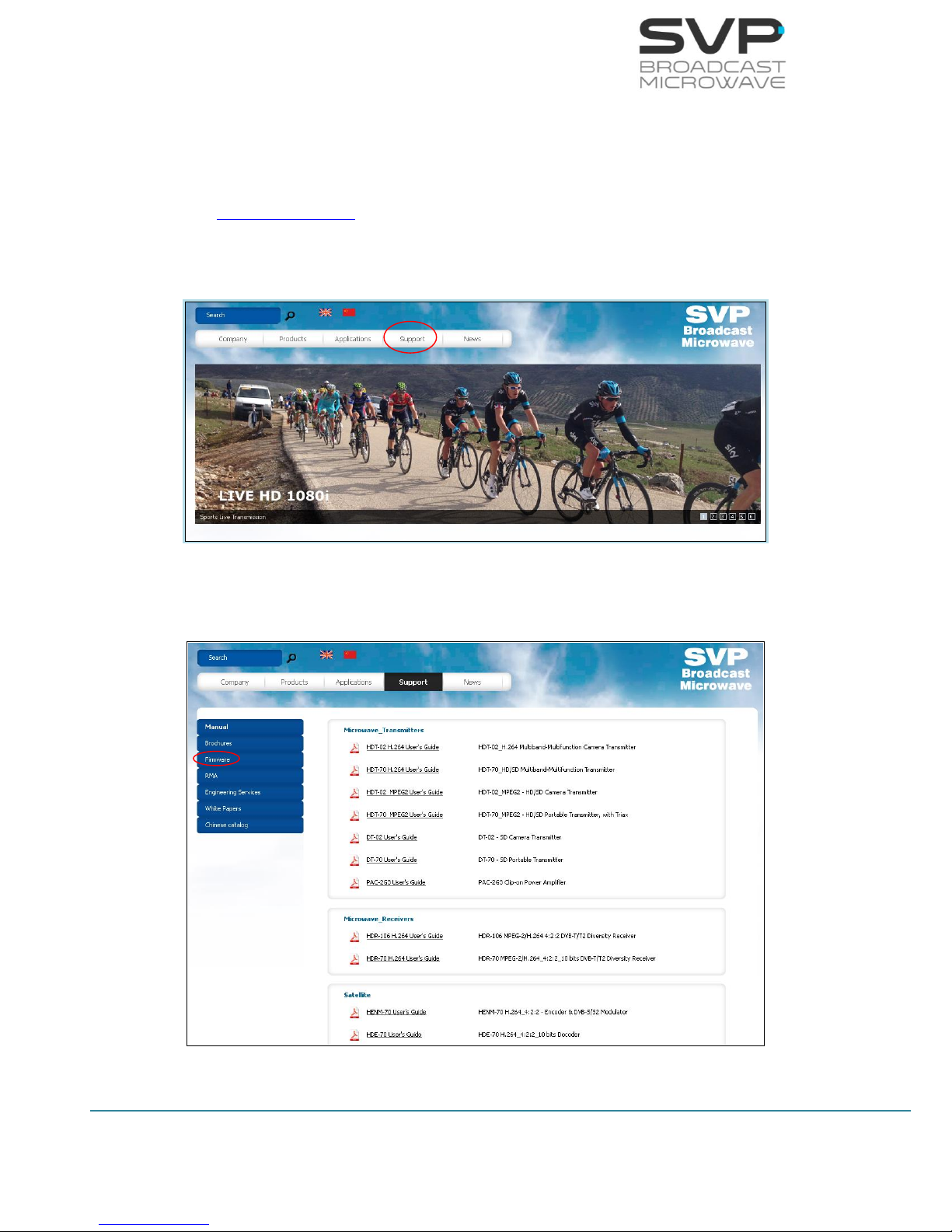
62
HDE-70 H.264 – 4:2:2 – 10 bits Decoder
MANUAL V6.9
In this section, the firmware of the device can be updated. Next, they are
explained the necessary steps so as to make a successful update.
1) The latest firmware is allocated in the webpage of SVP Broadcast
Microwave. So as to access to the firmware file, first enter
www.svpbm.com in your web browser.
2) Click on the Support tab.
Figure 3.61 Updating firmware step 2
3) Click on Firmware.
Figure 3.62 Updating firmware step 3
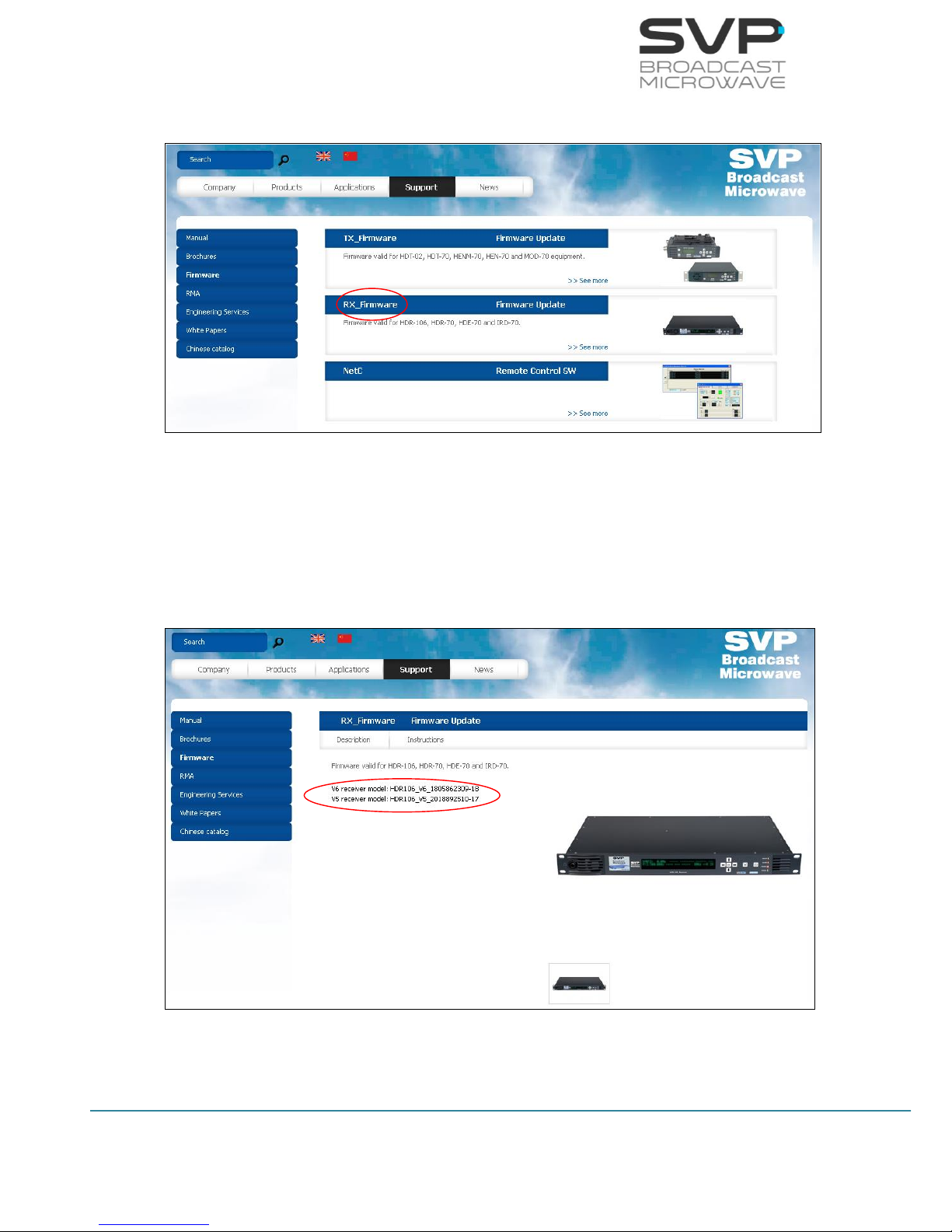
63
HDE-70 H.264 – 4:2:2 – 10 bits Decoder
MANUAL V6.9
4) Go to RX_Firmware.
Figure 3.63 Updating firmware step 4
5) Press the version of the receiver model needed (version of the
equipment) so as to download the file.
Go to Firmware field and then press the current version option to check
the number of the version installed in the device (the first two digits).
Figure 3.64 Updating firmware step 5
64
HDE-70 H.264 – 4:2:2 – 10 bits Decoder
MANUAL V6.9
6) Once the firmware file has been downloaded, save it in a USB device.
In the USB device, the only file that can be allocated inside it is the
firmware file of the device to be updated.
7) With the equipment completely powered off (with no power
supply), insert the USB device in the USB connector, situated in the
rear panel.
Before introducing the USB device, remove the power supply of the
equipment.
If there is no signal introduced in the device (RF, ASI or SDI), the updating
stage will be quicker.
8) Now, switch on the device.
9) Go to Unit menu. In case of being in the main screen, press the cross
button so as to access to the menu. There, with the Up, Down
buttons, select the Unit option.
10) Select Firmware by pressing the OK button.
11) Select Check USB Memory with the OK button.
12) Now, automatically the device updates the firmware. The screens
which are shown below display the different steps that the device is
makes while the updating process is taking place.
Don’t power off the device during the updating process.
Figure 3.65 Updating process 1
Figure 3.66 Updating process 2
FIRMWARE UPDATE
DON’T POWER OFF THE SYSTEM
Reading file 20%

65
HDE-70 H.264 – 4:2:2 – 10 bits Decoder
MANUAL V6.9
Figure 3.67 Updating process 3
Figure 3.68 Updating process 4
Figure 3.69 Updating process 5
Reading file 100% Checking file 80%
Reading file 100% Checking file 100%
Flashing 1/5 30%
UPDATE FINISHED
REBOOTING

66
HDE-70 H.264 – 4:2:2 – 10 bits Decoder
MANUAL V6.9
ASI: 9.9Mb H.264 576/50i 420/S AAG
(06 services) PROGRAM 001
Chapter 4: GPS
4.1 Introduction
The HDT-02 transmitter has a GPS antenna input in order to give
information to the device about the positioning data.
Once the information is kept inside the device, it can be sent to the
receiver. If the signal arrives correctly to the receiver system, then the
HDR-106 or any other receiver will be able to send GPS data to the HDE-70
throughout the ASI output and, then, the decoder will have all the GPS data
available and this decoder device will be able to calculate the direction,
distance, positioning... of the transmitter.
All of this information is shown in the GPS menu screen available in the
HDE-70 decoder.
The HDE-70 decoder also includes another feature that consists on an
output RS232 connection which allows watching throughout the Google
Maps application the position of the transmitter in real time.
4.2 Main Screen
Next it is explained the value of the data field which appears in the main
screen of the HDE-70 decoder.
Figure 4.1 Main screen
Data status field indicates with a darkened D that there is no data received.
If the ‘G’ does not vary, then it is connected to the satellites.
Darkened D no data
Undarkened D data
Undarkened G GPS data

67
HDE-70 H.264 – 4:2:2 – 10 bits Decoder
MANUAL V6.9
4.3 GPS Screen
So as to access to the GPS screen, go to the decoder option in the menu.
Once inside this option, go to the Decoder.Data field and choose GPS. Press
the OK button and then the GPS screen appears.
The format of the GPS coordinates used is decimal minutes as shown in the
next example:
N43º02.032’
W023º03.023’
Next there are shown the different fields meanings.
Figure 4.2 GPS screen
Latitude of the transmitter: It specifies the latitude position of the
transmitter.
Speed of the transmitter: It shows the speed of the transmitter in
knot.
Direction of the transmitter: The direction of the transmitter is shown
in this field.
#--º--.---´ ---k---º-----mt --/--/-#---º--.---´ S-- ----km ---º --:--:--
Rec Coords: #--º--.---´ #---º--.---´
Longitude of the
transmitter
Speed(knot)/
Direction(degrees)/
Height (meters) of the
transmitter
Date
Time
Nº of Satellites/
Distance from decoder to transmitter/
Direction from transmitter to
decoder(degrees)
Coordinates of
the decoder
Longitude
of the
decoder
Latitude
of the
decoder
Latitude of the
transmitter

68
HDE-70 H.264 – 4:2:2 – 10 bits Decoder
MANUAL V6.9
Height of the transmitter: The height of the transmitter from ground
is specified in this value.
Date: The updated data is shown.
Longitude of the transmitter: It specifies the longitude position of the
transmitter.
Nº of Satellites: The number of satellites connected to the GPS
antenna in the transmitter.
Distance from decoder to transmitter: The existence distance from
decoder to transmitter is displayed in this field.
Direction from transmitter to decoder: The direction of the
transmitter with respect to the decoder.
Coordinates of decoder.
Latitude of the decoder: In this field the user can enter the latitude of
the decoder.
Longitude of the decoder: In this field the user can enter the
longitude of the decoder.
4.4 Application example
Suppose the transmitter device is on an aeroplane and constant positioning
of the vehicle is wanted to be known. This is achievable with the next items:
- HDT-02_H.264 transmitter
- GPS antenna
- IRD
- HDE-70 decoder
With the GPS antenna connected to the HDT-02_H.264 transmitter,
positioning of the aeroplane is achieved once the GPS system is connected
to the necessary satellites. Data obtained in the transmitter is the
positioning of the aeroplane.
Next, this GPS data is sent through the RF output until it reaches the
demodulator. Next, this demodulator sends GPS data obtained to the HDE70 throughout the ASI or TS over IP output.
In the next page, a picture of this system is shown:

69
HDE-70 H.264 – 4:2:2 – 10 bits Decoder
MANUAL V6.9
GPS antenna
Figure 4.3 GPS system example picture
HDT-02
with GPS antenna
HDE-70 GPS screen
Decoder HDE-70
E20º45.512´ 10k47º1mt 04/10/13
N60º73.984´ S3 100km 100º 09:45:34
RS232 connection
PC with Google Earth
Video
- Power Amplifier
- Up Converter
- Parabolic Antenna
IRD
Transmitter System
Receiver System

70
HDE-70 H.264 – 4:2:2 – 10 bits Decoder
MANUAL V6.9
Chapter 5: Web Server
5.1 Introduction
This equipment can be controlled by use of a PC connected at the rear panel
Ethernet connector.
To enable the browser interface correctly the IP address, Subnet Mask,
Gateway, Admin Password and User Password need to be set correctly on
this unit. Next, the steps so as to setup network parameters are shown:
1. Go to Unit -> Webserver & SNMP
Figure 5.1 Web Server screen
2. Select Locl option and set an IP address. So as to change the IP
address first press the OK button and then, with the Up, Down keys
select the desired number. So as to change from one character to
another, press Right, Left keys. Press the OK button so as to save the
introduced value.
Figure 5.2 Local IP
04 Output
05 Unit
Unit Monitor
Unit Webserver & SNMP
Locl: 192.168.001.191
Mask: 255.255.000.000

71
HDE-70 H.264 – 4:2:2 – 10 bits Decoder
MANUAL V6.9
3. Select Mask option and set the Subnet Mask. So as to change the
Subnet Mask address first press the OK button and then, with the Up,
Down keys select the desired number. So as to change from one
character to another, press Right, Left keys. Press the OK button so
as to save the introduced value.
Figure 5.3 Subnet Mask
4. Select Gate option and set the Gateway. Select GAT option and set
the Gateway address. So as to change the Gateway address first
press the OK button and then, with the Up, Down keys select the
desired number. So as to change from one character to another,
press Right, Left keys. Press the OK button so as to save the
introduced value.
Figure 5.4 Gateway
5. Select Admin Pass option and set the administrator’s password. If it is
wanted to access to the Webserver directly without setting any
password, the Admin Pass must be set to 0 (00000000). However, if
it is wanted to set an administrator’s password, it is necessary to
introduce 8 digits. In this way, with this password, the administrator
can access to the Webserver and make any configuration,
modification or monitoring.
Figure 5.5 Admin Pass
6. Select User Pass option and set the user’s password. If it is wanted to
access to the Webserver directly without setting any password, the
User Pass must be set to 0 (00000000). However, if it is wanted to
set a user’s password, it is necessary to introduce 8 digits. In this
way, with this password, the user can access to the Webserver and
make any monitoring.
Locl: 192.168.001.191
Mask: 255.255.000.000
Mask: 255.255.000.000
Gate: 192.168.001.001
Gate: 192.168.001.001
Admin Pass: ********
Restore Def: >

72
HDE-70 H.264 – 4:2:2 – 10 bits Decoder
MANUAL V6.9
Figure 5.6 User Pass
Once the IP, Subnet Mask, Gateway, Admin Pass and User Pass are set and
the laptop or PC is connected to the HDE-70, open the web browser and tip
the IP given to the receiver.
Press the enter button in your computer and then the main screen will
appear.
Admin Pass: ********
Restore Def: >
User Pass: ********
Restore Def: >
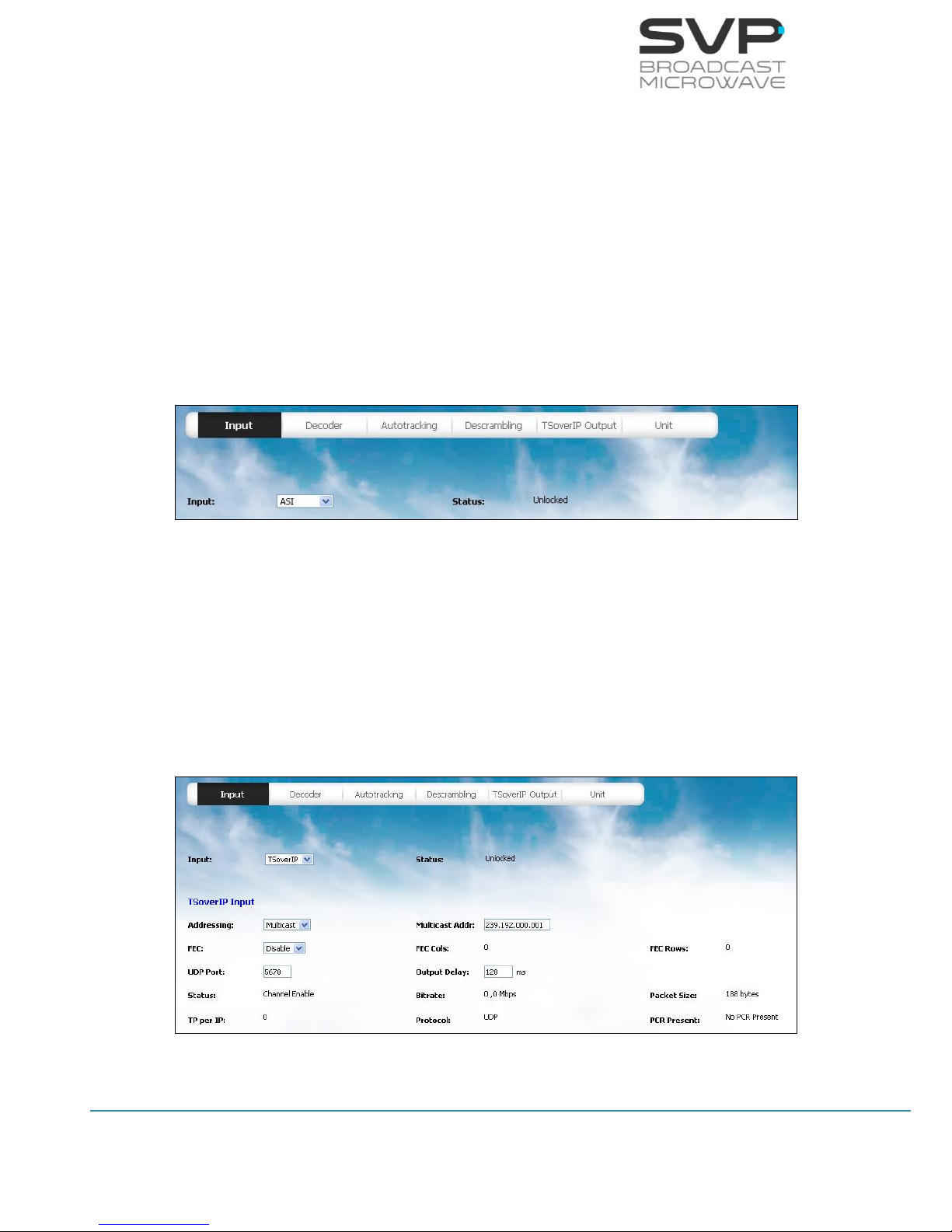
73
HDE-70 H.264 – 4:2:2 – 10 bits Decoder
MANUAL V6.9
5.2 Web Page Overview
The main menu is set in the upper position of the screen. Once an option is
chosen, it is possible to change any parameter allowed or to see the values
of some options.
In order to modify any parameter, introduce or select the new one and
press set button. Then the change will be set in the receiver device.
Next they are shown several screens of the web server and their features.
5.2.1 ASI INPUT
Figure 5.7 Web Server Unit screen
In this screen it is shown if ASI signal is being received through the
status field. If this field shows the locked word then, it means that
signal is present in the input of the device. If this field displays the
word unlocked then, it means that there is no signal in the input of
the device. (reading parameter)
5.2.2 IP INPUT
Figure 5.8 Web Server Unit screen

74
HDE-70 H.264 – 4:2:2 – 10 bits Decoder
MANUAL V6.9
- Addressing:
In this field it is configured if the IP packets received come from a
unicast address or from a multicast address. (eligible parameter)
- Multicast Address:
In this field the multicast address must be specified so as to receive
the information properly. (editable parameter)
- FEC:
In this option the FEC option can be enabled or disabled. In case the
enable option is selected, as the IP Forward Error Correction is
composed by a number of FEC columns and rows, it is shown the
number of FEC columns and rows of the received signal. (eligible
parameter)
- FEC Cols:
In this field the number of FEC columns of the received IP signal is
displayed. (reading parameter)
- FEC Rows:
In this field the number of FEC rows of the received IP signal is
displayed. (reading parameter)
- UDP Port:
In this field, the port number of the device through which is going to
receive the signal must be set. (editable parameter)
- Output Delay:
This delay means the time passed between the Transport Stream is
obtained in the decoder and the signal is taken out from the decoder.
(editable parameter)
- Status:
In this field the status of the IP input is displayed. (reading
parameter)
- Bitrate:
In this field the bitrate of the received signal is shown. (reading
parameter)

75
HDE-70 H.264 – 4:2:2 – 10 bits Decoder
MANUAL V6.9
- Packet Size:
In this field it is displayed the size in bytes of the Transport Stream
packets in the IP input. (reading parameter)
- TP per IP:
In this option the number of Transport Stream packets per IP packet
is displayed. (reading parameter)
- Protocol:
In this field the protocol used for the communication is displayed.
Two protocols are possible: UDP or RTP. (reading parameter)
- PCR Present:
Program Clock Reference. It indicates if PCR packets are found in
incoming TS. (reading parameter)
When editable parameters are being set in the Web Server and new
values are being introduced, the text remains in red colour until the
enter button is pressed. When the enter button is pressed, the new
values are saved and the text will appear in black colour. It is
necessary to press the enter button to keep and save the new values
on the screen.
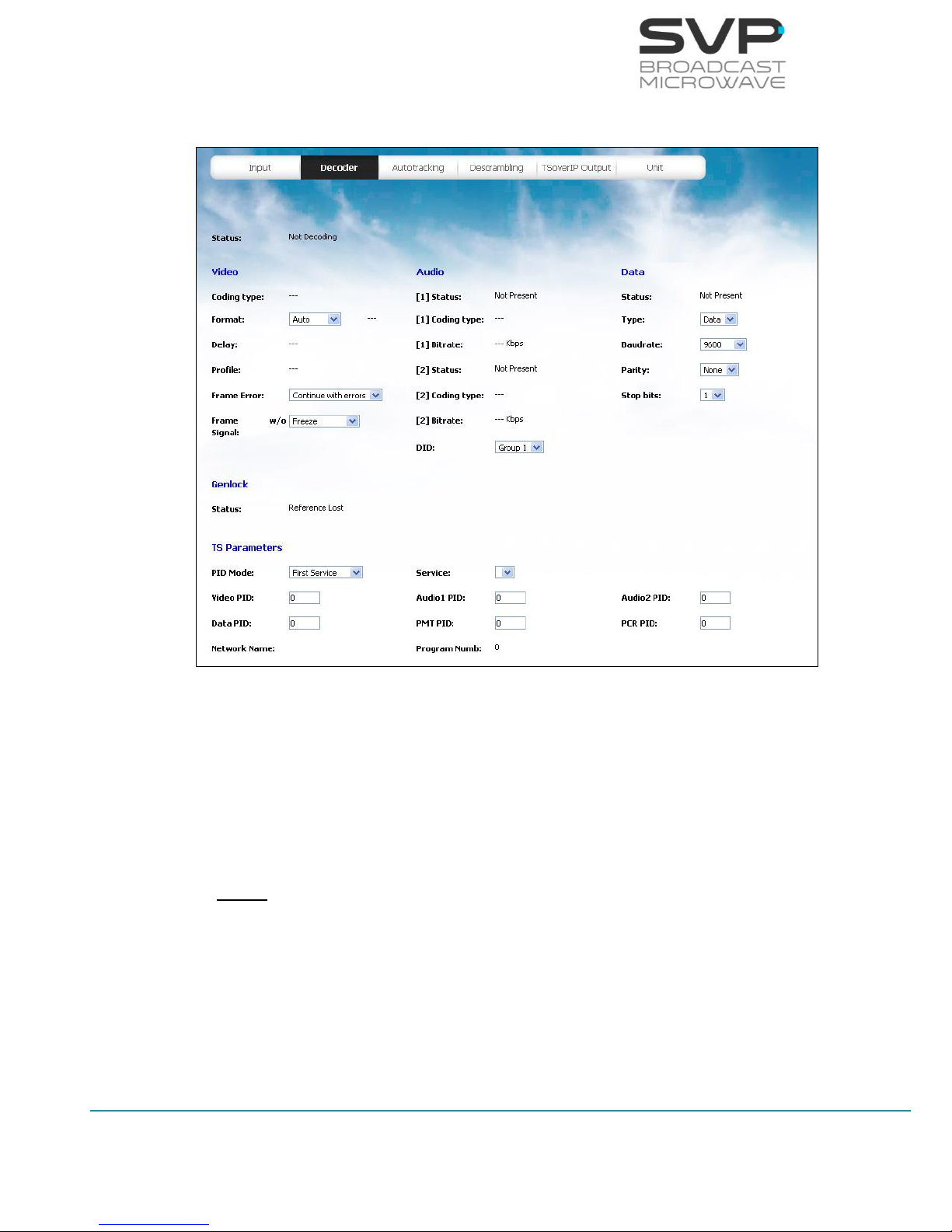
76
HDE-70 H.264 – 4:2:2 – 10 bits Decoder
MANUAL V6.9
5.2.3 DECODER
Figure 5.9 Web Server Decoder screen
- Status:
In this field, the status of the decoder is displayed. If the decoder is
not decoding, then the message “Not Decoding” appears. If the
decoder is decoding, then the word “Decoding” appears in this field.
(reading parameter)
Video
- Coding type:
This field shows the video coding type of the received video signal.
The available options are H.264 and MPEG-2. (reading parameter)
- Format:
This field shows the video format of the received signal. The available
options are 1080p, 1080i, 720p, 576i and 480i. (reading parameter)

77
HDE-70 H.264 – 4:2:2 – 10 bits Decoder
MANUAL V6.9
- Delay:
This field shows the video delay of the received signal. The available
options are Standard, Low Delay and Super Low delay. In case the
input video signal is coded in Ultra Low Delay mode, the device
decodes it but in the screen appears as Super Low Delay. (reading
parameter)
- Profile:
This field shows the video profile of the received signal. The available
options are 4:2:0 and 4:2:2. (reading parameter)
- Frame Error:
If there is a frame error, the broken image is shown in the screen to
advice that there has been an error. (eligible parameter)
The available options are:
Continue with errors: If there is an error, the image is shown
with errors in the screen.
Freeze: If there is an error, the image is frozen in the screen.
- Frame Signal
If there is an error, the last image is frozen in the screen until the
signal works again. (eligible parameter)
The available options are:
Freeze: The last image is frozen in the screen until the signal
works again.
Colour (10s): After 10 seconds, if there is not RF signal, the
screen becomes red. However, after 10 seconds, if there is no
video signal, the screen becomes blue.
Audio
- [1] Status:
This field shows the status of the audio 1. If there is no audio in the
audio 1 input, this field displays the message “Not Present”. If there
is audio in the audio 1 input, this field displays the word “Present”.
(reading parameter)

78
HDE-70 H.264 – 4:2:2 – 10 bits Decoder
MANUAL V6.9
- [1] Coding type:
This field displays the type of coding of the received audio 1 signal.
(reading parameter)
- [1] Bitrate:
This field displays the bitrate of the received audio 1 signal in Kbps.
(reading parameter)
- [2] Status:
This field shows the status of the audio 2. If there is no audio in the
audio 2 input, this field displays the message “Not Present”. If there
is audio in the audio 2 input, this field displays the word “Present”.
(reading parameter)
- [2] Coding type:
This field displays the type of coding of the received audio 2 signal.
(reading parameter)
- [2] Bitrate:
This field displays the bitrate of the received audio 2 signal in Kbps.
(reading parameter)
- DID:
It indicates in which audio group are going to be embedded the coded
audios. This DID is eligible from group 1 to group 4. (eligible
parameter)
Data
- Status:
This field shows the status of the data input. If there is no data in the
data input, this field displays the message “Not Present”. If there is
data in the data input, this field displays the word “Present”. (reading
parameter)
- Type:
There are two types of received data available (GPS or data). If GPS
data is selected, then, go to the GPS screen. If user data is selected,
then, the user can configure its parameters in the fields shown below.
(eligible parameter)

79
HDE-70 H.264 – 4:2:2 – 10 bits Decoder
MANUAL V6.9
- Baudrate:
In this field the baudrate at which the communication is stablished is
configured. The available baudrates are 2400, 4800, 9600, 19200,
38400, 57600, 78600, 115200. (eligible parameter)
- Parity:
In this field the parity of the data signal is configured. The available
options are None, Even and Odd. (eligible parameter)
- Stop bits:
In this field the number of stop bits of the data signal is configured.
The available options are 1 and 2. (eligible parameter)
Genlock
- Status:
This device has an external Genlock reference input in order to lock
all video outputs to it. In this field, the status of the genlock is
displayed. The available options are reference lost, reference
unlocked or reference locked. (reading parameter)
TS Parameters
- PID Mode:
In this field the mode for the decoding proccess is selected. If
automatic mode is selected, then, the device selects automatically
the PID values to decode. If the manual option is selected, then, the
user has to introduce the value of the different PIDs shown below.
(eligible parameter)
- Video PID:
In this field, the video packet identifier must be introduced. (editable
parameter)
- Audio1 PID:
In this field, the audio 1 packet identifier must be introduced.
(editable parameter)
- Audio2 PID:
In this field, the audio 2 packet identifier must be introduced.
(editable parameter)

80
HDE-70 H.264 – 4:2:2 – 10 bits Decoder
MANUAL V6.9
- Data PID:
In this field, the data packet identifier must be introduced. (editable
parameter)
- PMT PID:
In this field, the program map table packet identifier must be
introduced. (editable parameter)
- PCR PID:
In this field, the program clock reference packet identifier must be
introduced. (editable parameter)
- Network Name (only in Auto mode):
It displays the name of the network from which the signal comes.
(reading parameter)
- Program Number (only in Auto mode):
It displays the number of the program from which the signal comes.
(reading parameter)
When editable parameters are being set in the Web Server and new
values are being introduced, the text remains in red colour until the
enter button is pressed. When the enter button is pressed, the new
values are saved and the text will appear in black colour. It is
necessary to press the enter button to keep and save the new values
on the screen.

81
HDE-70 H.264 – 4:2:2 – 10 bits Decoder
MANUAL V6.9
5.2.4 Autotracking
Figure 5.10 Web Server Autotracking screen
So as to configure the GPS parameters, GPS option must be selected in the
decoder screen, in the type of data field.

82
HDE-70 H.264 – 4:2:2 – 10 bits Decoder
MANUAL V6.9
The format of the GPS coordinates used is decimal minutes as shown in the
next example:
N43º02.032’
W023º03.023’
Receiver Position
- Mode:
In this field, the available option is manual. In this mode, the user
must specify manually the parameters related to the position of the
receiver. (reading parameter)
- Latitude:
In this field the user must introduce the latitude of the receiver.
(editable parameter)
- Longitude:
In this field the user must introduce the longitude of the receiver.
(editable parameter)
- Altitude:
In this field the user must introduce the altitude of the receiver.
(editable parameter)
Transmitter Position
- Remote GPS
In this field, the source of the GPS signal can be selected. (eligible
parameter)
The available options are:
AUTO: The available option is selected. If both options are
available, UHF will be selected.
By HDT-02: If the GPS comes from the HDT-02 transmitter.
By UHF: If the GPS signal comes from the UHF radio.
- Latitude:
It shows the latitude position of the transmitter device. (reading
parameter)

83
HDE-70 H.264 – 4:2:2 – 10 bits Decoder
MANUAL V6.9
- Longitude:
It shows the longitude position of the transmitter device. (reading
parameter)
- Altitude:
The height of the transmitter from ground in feets is specified in this
value. (reading parameter)
- Speed:
This field shows the speed of the transmitter in knot. (reading
parameter)
- Direction:
The direction of the transmitter in degrees is shown in this field.
(reading parameter)
- Nr. Sat
The number of satellites is displayed in this field. (reading parameter)
- Tx-Rx Distance:
The existence distance from the receiver to the transmitter is
displayed in this field. (reading parameter)
- Tx-Rx Direction:
The direction of the transmitter in respect to the receiver is shown
in this field. (reading parameter)
- Tx-Rx Altitude:
The height of the transmitter in respect to the receiver is shown
in this field. (reading parameter)

84
HDE-70 H.264 – 4:2:2 – 10 bits Decoder
MANUAL V6.9
Parabolic Antenna Configuration
- Polarity
The polarity of the antenna is selected. (eligible parameter)
The available options are: None, Vertical, Horizontal, RHCP and LHCP.
- H.Offset
The desired offset of the antenna can be selected. (editable
parameter)
- Fold Tilt
The number of degrees that are needed to fold the antenna is
displayed. (editable parameter)
Sectorial Antenna Configuration
- Elevation Degree
In this field, the elevation degree of the receiver antenna is selected.
(elegible parameter)
- Nr. Sectors
In this option, the number of sectors of the antenna can be selected
(from 1 to 8). (eligible parameter)
- Top Sector
In this option, if a top antenna is included is selected. (eligible
parameter)
The available options are: Yes or No.
Autotracking
- Antenna Select:
In this field the type of antenna of the autotracking system can be
selected. (eligible parameter)
The available options are: Parab, Sector and Omni.
- Parabolic
In this field, parabolic autotracking option is configured. This option
allows the user to choose different types of situations:

85
HDE-70 H.264 – 4:2:2 – 10 bits Decoder
MANUAL V6.9
Auto: It is the auto mode for GPS.
Manual: Choosing this option, the parameters of the parabolic
antenna can be configured.
o Pan: Azimuth position of the antenna
o Tilt: Elevation position of the antenna
Fold: The fold option is enabled.
- Sectorial
In this field, sectorial autotracking option is configured. This option
allows the user to choose different types of situations for the sectorial
autotracking system:
Auto: It is the auto mode for GPS.
Sector 1-8: Using these options, user can choose which of
these sectors are going to be enabled for the reception of the
signal.
Besides, another parameters are shown in the autotracking field:
[Tw] Level: In this field, the level of the received signal, where w is
the number of the demodulator (from 1 to 6 diversity
mode), is shown in dBm. (reading parameter)
[Tw] SNR: In this field, the Signal Noise to Ratio value of the received
signal, where w is the number of the demodulator (from 1
to 6 for diversity mode), is displayed in dB. (reading
parameter)
When editable parameters are being set in the Web Server and new
values are being introduced, the text remains in red colour until the
enter button is pressed. When the enter button is pressed, the new
values are saved and the text will appear in black colour. It is
necessary to press the enter button to keep and save the new values
on the screen.

86
HDE-70 H.264 – 4:2:2 – 10 bits Decoder
MANUAL V6.9
5.2.5 DESCRAMBLING
Figure 5.11 Web Server Descrambling screen
- Status:
In this field, the status of the descrambling process is displayed. If
the input signal is not encrypted, then the message Not Scrambled
appears. If the device is descrambling, then the word scrambled
appears in this field. (reading parameter)
- BISS Mode:
Select the BISS encryption mode. (eligible parameter)
- Session Work:
Key for BISS-1 and BISS-E. The values of each characer introduced
can be from 0 to 9 and from A to F. (editable parameter)
- User ID:
User ID for BISS-E. The values of each character introduced can be
from 0 to 9 and from A to F. (editable parameter)
When editable parameters are being set in the Web Server and new
values are being introduced, the text remains in red colour until the
enter button is pressed. When the enter button is pressed, the new
values are saved and the text will appear in black colour. It is
necessary to press the enter button to keep and save the new values
on the screen.

87
HDE-70 H.264 – 4:2:2 – 10 bits Decoder
MANUAL V6.9
5.2.6 IP Output
Figure 5.12 Web Server Output screen
IP Output (This option is available if the IP Input is not
selected)
- Destination address:
In this option, the IP address of the device to which data is sent must
be configured. In case it is wanted to send data to a multicast
address just enter the desired multicast address. (editable
parameter)
- UDP Port:
In this option, the port number of the device to which data is sent
must be configured. (editable parameter)
- FEC:
In this field the Forward Error Correction can be enabled or disabled.
In case it is enabled, the number of columns and rows can be
configured. If FEC option is enabled then, the only protocol which can
be used is RTP. (eligible parameter)
- TP per IP:
In this field the number of Transport Stream packets per IP (from 1
to 7) can be configured. (editable parameter)

88
HDE-70 H.264 – 4:2:2 – 10 bits Decoder
MANUAL V6.9
- Protocol:
In this field the type of protocol used for the communication is
selected. The type of protocol used for the communication can be RTP
or UDP. (eligible parameter)
- Time to Live [0..255]:
This field limits the lifetime of data. The Time to Live value (from 1 to
255) means the number of routers that a packet can reach until that
packet is discarded. (editable parameter)
- IP/ASI Output:
In this field, the use of the BISS encryption in the IP and ASI outputs
of the decoder can be configured. (eligible parameter)
The available options are:
Standard:
In this option, if the transmitter’s signal is encrypted, there will
be encryption in the IP and ASI outputs of the decoder. If the
transmitter’s signal works without encryption, there will not be
encryption in the ASI and IP outputs of the decoder.
Always Descrambled:
In this option, the IP and ASI outputs of the decoder will always
be without encryption.
When editable parameters are being set in the Web Server and new
values are being introduced, the text remains in red colour until the
enter button is pressed. When the enter button is pressed, the new
values are saved and the text will appear in black colour. It is
necessary to press the enter button to keep and save the new values
on the screen.
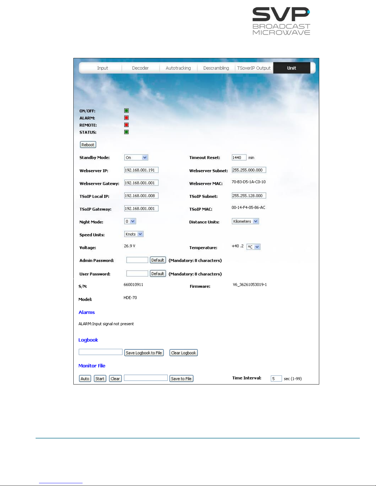
89
HDE-70 H.264 – 4:2:2 – 10 bits Decoder
MANUAL V6.9
5.2.7 UNIT
Figure 5.13 Web Server Unit screen

90
HDE-70 H.264 – 4:2:2 – 10 bits Decoder
MANUAL V6.9
First of all, the status of the different LEDs available is presented. These
LEDs provide specific information about the status of the receiver:
ON/OFF:
The Led lights up in green when the equipment is turned on and it
turns up in red if the equipment is turned off.
ALARM:
The Led lights up in red when any alarm occurs.
REMOTE:
The Led lights up in green when the user is connected remotely to
the device.
STATUS:
The Led lights up when a change in the configuration of the device is
being processed.
Configuration
- Standby Mode:
In this option HDR-106 receiver will be in standby or in ON mode.
- Timeout Reset:
In this field the time that the receiver could be without receiving any
signal is selected. After passing this time, the equipment is reset. To
disable this option, 0 value must be written. (editable parameter)
- Webserver IP:
In this field, the IP address for the Webserver connection can be
configured. (editable parameter)
- Webserver Subnet:
In this field, the Subnet address for the Webserver connection can be
configured. (editable parameter)
- Webserver Gateway:
In this field, the Gateway address for the Webserver connection can
be configured. (editable parameter)
- Webserver MAC:
In this field, the MAC address of the device is shown. (reading
parameter)

91
HDE-70 H.264 – 4:2:2 – 10 bits Decoder
MANUAL V6.9
- TSoIP Local IP:
In this field, the IP address of this device for the Video over IP
connection can be configured. (editable parameter)
- TSoIP Subnet:
In this field, the Subnet address of for the Video over IP connection
device can be configured. (editable parameter)
- TSoIP Gateway:
In this field, the Gateway address of this device for the Video over IP
connection can be configured. (editable parameter)
- TSoIP MAC:
In this field, the MAC address of this device for the Video over IP
connection is shown. (reading parameter)
- Night Mode:
There are four possible states for the night mode. If night mode is in
state 0 then the light in the screen will shine more than if it is in state
1. If the state is three then, the light in the screen will be the lowest
of the four possible states. (eligible parameter)
- Distance Units:
If miles is selected then, all the distances will be in miles and the
same occurs if kilometers is selected. (eligible parameter)
- Speed Units:
The speed can be measured in knots, km/h or Mph. (eligible
parameter)
- Voltage:
In this field, the power supply voltage of the device is shown.
(reading parameter)
- Temperature:
If ºC is selected then, the temperature value will be shown in ºC and
the same occurs in case ºF is selected. (eligible parameter)
- Admin Password:
In this field, user can enter the administrator password. (elegible
parameter)

92
HDE-70 H.264 – 4:2:2 – 10 bits Decoder
MANUAL V6.9
- User Password:
In this field, user can enter the user password. (elegible parameter)
- S/N:
In this field, the serial number of the device is shown. (reading
parameter)
- Firmware:
In this field, the version of the equipment is shown. (reading
parameter)
- Model:
In this field, the model of the device is shown. (reading parameter)
Alarms
In this option, different alarms which are present in the device are shown.
The different alarms that can appear in the decoder are:
- Input Signal Not Present
- No Video Present
- DC Voltage Low
- DC Voltage High
- High Temperature
When editable parameters are being set in the Web Server and new
values are being introduced, the text remains in red colour until the
enter button is pressed. When the enter button is pressed, the new
values are saved and the text will appear in black colour. It is
necessary to press the enter button to keep and save the new values
on the screen.
Logbook
Figure 6.14 Logbook
This field allows the user to access to the Logbook menu where the
different events that took place are shown and dump them in a text
file.
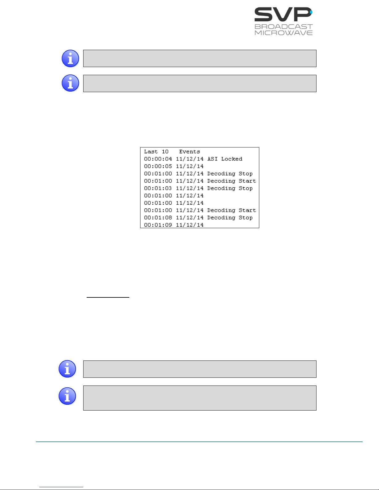
93
HDE-70 H.264 – 4:2:2 – 10 bits Decoder
MANUAL V6.9
This feature is supported using Firefox and Chrome navigators.
Internet Explorer is not supported.
While the data is being saved, it is necessary to remain in the Unit
section of the Webserver.
If it is wanted to dump the different events in a file, type the name of
the file and the extension and press Save Logbook to File. Then, open
the file which has been downloaded on the computer and the
information about the different events will be shown (time of the
event, date of the event and description of the event).
Figure 6.15 Logbook information
If it is wanted to clear de Logbook, press Clear Logbook button.
Monitor File
In this file, the information related to the latitude, longitude and
altitude of the transmitter and receiver, the decoding status and the
LEVEL, MER and C/N of each signal is displayed.
To export this information in a text file, it is important to consider the
following items:
This feature is supported using Firefox and Chrome navigators.
Internet Explorer is not supported.
While the data is being captured, it is necessary to remain in the Unit
section of the Webserver. If you change to another section, the
captured data will be lost.
 Loading...