


DR-100 Series COFDM
DIGITAL RECEIVER
Versions: DR-102 Diversity 2
DR-106 Diversity 6
USER’S MANUAL
Version 1.1
SVP
Broadcast
Microwave

2
Contents
Chapter 1: Introduction
The objective of this first part is to provide a general description of the DR100 receiver.
Chapter 2: Connections
This second part offers a detailed description of each of the connections on
the DR-100 receiver.
Chapter 3: Technical features
The objective of this chapter is to provide detailed technical features of the
DR-100 receiver: inputs, outputs, power supply, remote control, and
physical and environmental characteristics.
Chapter 4: Front panel controls on the demodulator unit.
This chapter offers a detailed description of every the control on the front
panel of the rack-mount demodulator unit.
Chapter 5: Local control of the equipment
This chapter provides a detailed description of the local control procedures
for the DR-100 receiver, using the display and the keypad on the rackmount demodulator unit. Each of the menus and sub-menus are described
in detail. Required steps to configure and monitor the unit’s parameters are
defined.
Chapter 6: NetC Software to control remotely a network of
SVP equipment
This chapter provides a detailed description of NetC software. This program
allows the control of several SVP systems at the same time, provided they
all are in the same local area network.
Chapter 7: Remote control via RS-232 connection
This chapter provides a detailed description of how to remotely control the
DR-100 series receivers via a RS-232 connection.

3

4
DEAR CUSTOMER:
We would like to thank you for selecting this equipment and welcome you to
the SVP’s growing family of products.
We are sure that the addition of this equipment to your existing installation
will cause you nothing but satisfaction.
Please read these instructions carefully, and keep them at hand in case you
have to refer to them.

5
IMPORTANT NOTES:
1. The DR-100 series digital COFDM receiver is completely compatible with
the DVB-T standard included in European Standard ETSI EN300744.
2. There are two different models available: the DR-102 diversity 2 receiver
and the DR-106 diversity 6 receiver. Two down-converters can be
connected to the DR-102 receiver and up to 6 down-converters can be
connected to diversity 6 receiver. Each down-converter is connected to
an independent receiver antenna in order to provide diversity.
3. The complete receiver system consist of two parts: first, the down-
converters installed outdoors next to the receiver antennas and second
the rack control unit DR-102 or DR-106 installed indoors which
demodulates and decodes received incoming signal from the downconverters.
4. DR-100 series receivers usually work with SVP DC-COFDM down-
converters, which are available in bands of 500MHz in the frequency
range from 1.3 to 10.5GHz
5. In the receiver’s site is important to determine if the channel in which
the transmission will be carried out is interfered. In addition, special care
must be taken in 2400 to 2500MHz band, due to the possible presence
of WiFi signals.
6. While installing the equipment, the power supply to the down-converters
should be disabled in the Setup configuration menu of the rack-mount
demodulator unit, to avoid the risk of short-circuits.
7. The receiver system must be well chilled. Some space must be left next
to the sides of the equipment for ventilation purposes. This is especially
important when it is installed in a rack case.
8. If you wish to install the rack-mount demodulator unit horizontally,
guides should be used, due to the weight of the equipment.
9. It is not advisable to use a power lead with a cross section smaller than
that of the lead supplied, sing this would cause a drop in the supply
voltage and deficient operation of the equipment.
10.The front panel of the DR-100 series receivers is automatically locked
when the user stops manipulating the equipment for 30 minutes.
11.Only authorized personnel should open the product and any repair or
warranty will be invalidated is the seals are open.

Contents
1 Description ......................................................................... 1
List of figures
Figure 1.1 Connection diagram of the DR-100 series equipments .............. 1
Figure 1.2 A flight case for the rack-mount demodulator .......................... 2
Chapter 1
Introduction

Chapter 1: Introduction
1
1 Description
The DR-100 series COFDM digital receivers receive the signal from the
down-converters which are installed outdoors next to the receiver antenna.
It demodulates and decodes incoming signal. Afterward the signal sent by
the transmitter is obtained at its outputs in video, SDI and ASI formats.
Figure 1.1 Connection diagram of the DR-100 series equipments
There are two different models available: the DR-102 diversity 2 receiver
and the DR-106 diversity 6 receiver. Two down-converters can be
connected to the DR-102 receiver and up to 6 down-converters can be
connected to diversity 6 receiver. Each down-converter is connected to an
independent receiver antenna in order to provide diversity. This allows
several different antennas to be installed, in order to take advantage of
their combined characteristics, or several antennas, of similar types or
different types can be installed oriented in different directions to offer wider
coverage. Using a diversity system makes the link more robust and offers
better performance than a non-diversity system.
The complete receiver system consist of two parts: first, the downconverters installed outdoors next to the receiver antennas and second the
rack control unit DR-102 or DR-106 installed indoors which demodulates
and decodes received incoming signal from the down-converters.
DR-100 series receivers usually work with SVP DC-COFDM down-converters,
which are available in bands of 500MHz in the frequency range from 1.3 to
10.5GHz
The diversity technique used in the DR-100series digital COFDM receivers is
known as "Maximum Ratio Combining” (MRC), in which the signal to be
demodulated is the result of combining the best sub-carriers in each signal
delivered by the down-converters; in other words, the unit does not simply
select the input signal from one of the down-converters, it combines these
signals in such a way that the signal used by the demodulator is always the
best signal available.

Chapter 1: Introduction
2
The IF signals delivered by the down-converters are fed into the rack-mount
demodulator, which demodulates them using the MRC diversity technique
and then decodes them to obtain two composite video signals, two SDI
digital signals, four analogue audio signals and four digital audio signals
embedded in the SDI signal. All models of the DR-100 series also have a
DVB-ASI transport stream output that can be extremely useful if several
decoders are to be chained or to implement an intermediate ASI feed
without having to decode it. They also have a Genlock reference input in
order to lock the SDI output signals.
This equipment is capable to receive GPS data or other data types
introduced, at different speeds, in the data channel in SVP transmitters.
The display and the keypad on the front panel of the demodulator
equipment can be used to monitor many parameters of interest, such as the
modulation, the Viterbi coding or the FEC, and the guard interval used
(obtained when the TPS, [Transmission Parameter Signalling] carriers are
demodulated), signal levels, link quality parameters such as the SNR, the
MER and the BER and the presence of alarms and/or warnings.
When steering the antennas, the main screen showing the signal levels and
the SNR of the IF inputs is very helpful. These measurements are displayed
as a bar graph and as numerical values. The numerical values do not
express signal levels or SNR in dB, they are merely indicative. The scale for
the signal levels is from 1 to 100, and the SNR values range from 1 to 10.
These measurements are really useful while orienting the antennas.
There is also a UDP/IP Ethernet link that allows these and many other
parameters to be controlled and monitored from a remote station.
The equipment can be AC mains powered or run off DC batteries. The
switchover from the mains to batteries is automatic. The down-converters
are powered from the demodulator unit via the IF coaxial cable that
connects them together.
The Down-Converters are waterproof and are installed next to the reception
antennas.
An optional flight case is available for the rack-mount demodulator. Its size
is 2 units rack; consequently, two equipments can be transported in it.
Figure 1.2 A flight case for the rack-mount demodulator

3
Contents
1 Introduction ........................................................................ 4
2 Power supply ...................................................................... 5
3 Video ................................................................................. 5
4 Audio ................................................................................. 6
5 DVB-ASI ............................................................................. 6
6 Genlock .............................................................................. 6
7 Data Out ............................................................................ 6
8 Remote control .................................................................... 7
9 Down-converter .................................................................. 7
10 Antenna ............................................................................. 7
List of figures
Figure 1.1 Back view of the rack-mount demodulator .............................. 4
Figure 1.2 The down-converter ............................................................. 4
Figure 9.1 Connection of the receiver antenna ........................................ 7
Chapter 2
Connections
Chapter 2: Connections
4
1 Introduction
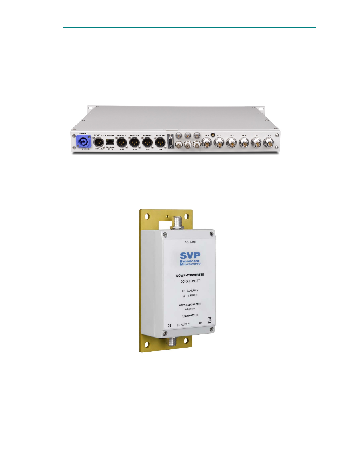
All connectors of the rack-mount demodulator unit are on the rear panel, as
shown in the figure below:
Figure 1.1 Back view of the rack-mount demodulator
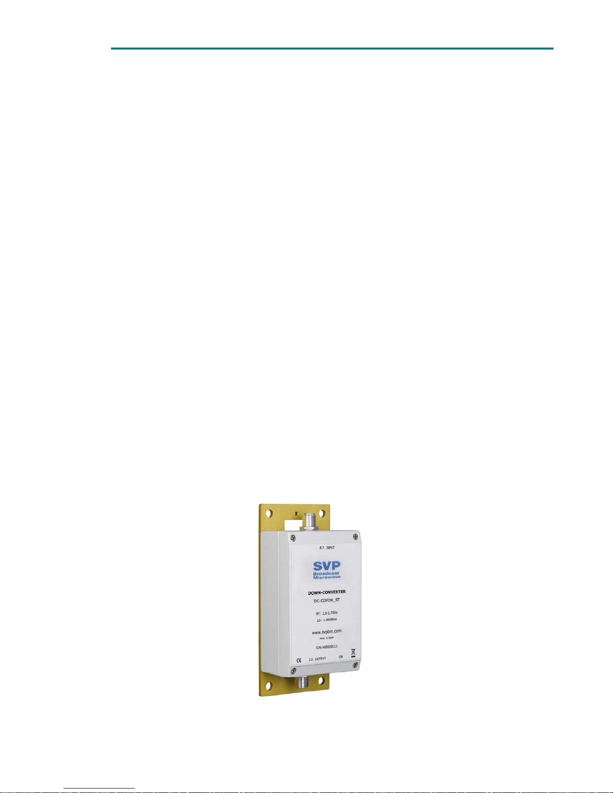
On the other hand, the connectors on the down-converter are on both the
top panel and the bottom panel, as shown below:
Figure 1.2 The DC down-converter
Chapter 3 offers detailed technical features of all of the connectors.

Chapter 2: Connections
5
2 Power supply
The equipment can be powered by an AC source between 90 and 240V, or a
DC source of 11 to 36 V. The down-converters are powered from the rackmount demodulator unit via the IF coaxial cable that connects them
together.
When the equipment is powered by an AC source, this is connected to a
switching power supply that gives a 12V output.
The power-supply board receives either the 12V supply from this power
supply or a DC voltage between 11 and 36V from the DC power input, and
converts the input to the supply voltages required by the equipment:
+3.3V, +5V, +12V and –12V.
The mains frequency should be between 50 and 60 Hz.
The AC mains input uses a Neutrik MLC connector. A cable with the required
connectors is supplied with the equipment.
The AC power connector used in this equipment is designed to prevent
accidental disconnection. To extract the connector, pull back the locking clip
and rotate the connector, as indicated on the connector itself.
It is not advisable to use a power lead with a cross-section less than that of
the lead supplied, since this would cause a drop in the supply voltage and
deficient operation of the equipment.
The DC power supply is connected via a Neutrik 4-pin male XLR connector
with a safety clip to prevent accidental disconnection.
The IF inputs of the demodulator supply +12V to power the downconverters.
3 Video
The DR-100 series receivers include two analogue composite video outputs
and two SDI digital video outputs.
Each of these signals is available on 75Ω insulated BNC connectors located
on the rear panel of the rack-mount demodulator unit.
The SDI digital video outputs are compatible with the SMPTE-259M
standard.
We recommend the use of RG-59 video cable. If this type is not used, we
recommend that the cable used that does not attenuate the high-frequency
components of the video signal. When the cable has been selected, it is
important to determine the length required. For cables longer than 50m, it
is advisable to check the cable and the losses that occur on them.

Chapter 2: Connections
6
It is important that 75Ω connectors be used. This is because the female
output connector of the demodulator unit may be damaged, and because an
impedance mismatch will occur.
4 Audio
The DR-100 series receivers deliver analogue audio signals and digital audio
signals embedded in the SDI signal.
The equipments have four analogue audio outputs, available on 3-pin male
XLR connectors on the rear panel of the rack-mount demodulator unit.
The pinout of the XLR-3 connectors is the following one:
PIN-1: Ground
PIN-2: Hot (+)
PIN-3: Cold (-)
For the output connections of the digital audio signals embedded in the SDI
signal they can be used the same 75Ω insulated BNC connectors that are
used to transport the digital video signals.
The SDI digital video outputs with the four digital audio signals embedded
in each of them are compatible with the SMPTE-272M standard.
5 DVB-ASI
The DR-100 series receivers have a DVB-ASI Transport Stream output,
compatible with the EN50083-9 standard, available on an insulated 75Ω
BNC connector on the rear panel of the rack-mount demodulator unit.
This output may be extremely useful if an intermediate ASI feed is required
without needing to decode the audio and video signals and then recode
them into MPEG-2 in the transmitter equipment.
6 Genlock
The DR-100 receivers have a Genlock external reference input in order to
lock the video and SDI digital outputs to it. The connection is available on a
75Ω insulated BNC connector located on the rear panel of the rack-mount
demodulator unit.
7 Data Out
The DR-100 receiver can get data introduced to the data channel of the SVP
transmitters. The information is available in a DB9 connector in the rear
panel of the rack equipment.
Chapter 2: Connections
7
The receiver can also be controlled remotely via an RS-232 connection.
From the set up menu the user will establish whether the DB9 port will be
used as a data out port or as a remote control port.
8 Remote control
The DR-100 series receivers can be controlled and monitored remotely over
an Ethernet link.
The link is connected via an 8-pin RJ-45 connector with a 10/100 Base-T
network interface. This connector is located on the rear panel of the rackmount demodulator.
9 Down-converter
The connection between the rack-mount demodulator unit and the downconverter uses coaxial cable, whose maximum length depends on the type
of coaxial cable used. If the Celflex ½” coaxial cable is used, the maximum
length is 150m but if the RG-214 coaxial cable is used, the maximum length
is reduced to 75m.
10 Antenna
The antenna is connected to the female N-type connector on the top panel
of the down-converter.
The down-converter can be mounted next to the receiver antenna on a
mast with a maximum diameter of 60mm. This provides a simple, easy
mounting method, as can be seen in the photograph below:
Figure 10.1 Connection of the receiver antenna

Chapter 2: Connections
8
The fittings to clamp the down-converter to the mast are supplied with the
down-converter.

Chapter 3: Technical features
9
Contents
1 Inputs .......................................................................... 10-10
1.1 RF Section ....................................................................... 10-10
1.2 IF Section ........................................................................ 10-10
1.3 Genlock .......................................................................... 10-11
2 Outputs ......................................................................... 2-11
2.1 SDI (Serial Digital Interface) ................................................ 2-11
2.2 Composite video ................................................................. 2-12
2.3 Analogue audio outputs ....................................................... 2-12
2.4 ASI OUT ............................................................................ 2-13
2.5 Data Out ........................................................................... 2-13
3 Power supplies ............................................................... 3-13
3.1 AC Power .......................................................................... 3-13
3.2 DC Power .......................................................................... 3-13
4 Remote control ............................................................... 4-14
5 Physical characteristics .................................................... 5-14
6 Environmental conditions ................................................. 6-14
List of tables
Table 1.1 RF input features ........................................................... 10-10
Table 1.2 IF (Intermediate Frequency) input features ....................... 10-10
Table 1.3 Genlock external reference input features ......................... 10-11
Table 2.1 SDI output features ......................................................... 2-11
Table 2.2 Composite video output features ........................................ 2-12
Table 2.3 Audio output features ....................................................... 2-12
Table 2.4 DVB-ASI Transport Stream output features ......................... 2-13
Table 2.5 Data Out output features .................................................. 2-13
Table 3.1 AC power supply features ................................................. 3-13
Table 3.2 DC power supply features ................................................. 3-13
Table 4.1 Remote control ................................................................ 4-14
Table 5.1 Physical characteristics of the rack-mount demodulator unit .. 5-14
Table 5.2 Physical characteristics of the down-converter ..................... 5-14
Table 6.1 Environmental features .................................................... 6-14
Chapter 3
Technical features

Chapter 3: Technical features
10
1 Inputs
1.1 RF Section
Table 1.1 RF input features
Item Feature
Connector designation RF INPUT
Type of connector Female “N” type
Impedance 50Ω
Input frequency ranges 1.3 to 10.5GHz
(in 500MHz bands)
Noise figure <2 dB
Minimum input signal level QPSK: 1/2: -95 dBm
2/3: -94 dBm
3/4: -93 dBm
5/6: -92 dBm
7/8: -91 dBm
16QAM: 1/2: -87 dBm
2/3: -86 dBm
3/4: -85 dBm
5/6: -84 dBm
7/8: -83 dBm
64QAM: 1/2: -80 dBm
2/3: -79 dBm
3/4: -78 dBm
5/6: -77 dBm
7/8: -76 dBm
IP3 of the internal LNA +33 dBm
Phase noise <-98 dBc/Hz@10KHz
Conversion gain >25dB
Number of poles of the input filter 5 (Interdigital)
Static protection Yes
1.2 IF Section
The DR-100 series receivers have one, two or six IF inputs, depending on the
model (DR-102 or DR-106). The features are shown in the table below:
Table 1.2 IF (Intermediate Frequency) input features
Item Feature
Connector designation Demodulator: IF1...IF6
Down-converter: I.F.
OUTPUT&DC
Type of connector Demodulator: N female
Down-converter: N female
Frequency ranges 48 to 860 MHz
Impedance 50Ω
Maximum length of IF cable RG-214: 75m
Celflex1/2”: 150m

Chapter 3: Technical features
11
Diversity Up to 6 using the MRC
technique (Maximum Ratio
Combining)
Bandwidth 5 MHz, 6 MHz, 7 MHz or 8 MHz
Constellation QPSK, 16-QAM or 64-QAM
Guard interval 1/4, 1/8, 1/16, 1/32
FEC 1/2, 2/3, 3/4, 5/6, 7/8
Mode 2K
1.3 Genlock
The DR-100 series receivers have a Genlock reference input to lock the SDI
digital video outputs to an external source.
Table 1.3 Genlock external reference input features
Item Feature
Connector designation Genlock
Type of connector Insulated BNC female
Impedance 75Ω
Signal level From 0.5 to 4 Vpp
2 Outputs
2.1 SDI (Serial Digital Interface)
The DR-100 series receivers have two SDI digital video outputs, whose features
are shown in the following table:
Table 2.1 SDI output features
Item Feature
Connector designation SDI
Type of connector Insulated BNC female
Impedance 75Ω
Output level 800mVpp nominal ±10%
Return losses > 15 dB, 5-270 MHz
Bitrate 270 Mbit/s
Standard SMPTE-259M
Video decoding standard MPEG-2 (ISO/IEC 13818-2):
- 422P@ML
- MP@ML
- Super low delay
Video format
- 525i
- 625i
Aspect ratio
- 4/3
- 16/9

Chapter 3: Technical features
12
2.2 Composite video
The DR-100 series receivers include two composite video outputs. Their features
are shown in the table below:
Table 2.2 Composite video output features
Item Feature
Connector designation VIDEO
Video connector Insulated BNC female
Impedance 75Ω
System PAL
Video decoding standard MPEG-2 (ISO/IEC 13818-2):
- 422P@ML
- MP@ML
- Super low delay
Video format
- PAL
- NTSC
Aspect ratio
- 4/3.
- 16/9.
2.3 Analogue audio outputs
The DR-100 series receiver includes four audio outputs. Their features are
shown in the table below:
Table 2.3 Audio output features
Item Feature
Number of audio channels 4
Connector designations AUDIO 1 LEFT
AUDIO 1 RIGHT
AUDIO 2 LEFT
AUDIO 2 RIGHT
Audio connectors XLR-3 male
Audio output level Line, +15dBm maximum
Impedance 30Ω
Sampling frequency 48 KHz
Audio decoding standard MPEG-1 L2
The pinout of the audio connectors is
Pin 1=> ground
Pins 2 and 3 => signals

Chapter 3: Technical features
13
2.4 ASI OUT
Table 2.4 DVB-ASI Transport Stream output features
Item Feature
Connector designation ASI OUT
Type of connector Insulated BNC female
Impedance 75Ω
Standard EN50083-9
Packet length 188/204 bytes
Maximum bitrate 31 Mbit/s
2.5 Data Out/RS-232 remote control
Table 2.5 Data Out output features
Item Feature
Connector designation Data out
Type of connector DB9
Standard RS-232
Output bitrate 2400 to 115.200bps
3 Power supplies
3.1 AC Power
Table 3.1 AC power supply features
Item Feature
Connector designation POWER A.C.
Connector Neutrik MLC
Supply voltage 90-240 V. (50/60Hz)
3.2 DC Power
Table 3.2 DC power supply features
Item Feature
Connector designation POWER D.C.
Connector XLR-4 male
Supply voltage 11-36 V.
Consumption Down-converter:450mA@12V
The pinout is:
Pins1 and 2 => ground
Pins 3 and 4 => +11V to +36V

Chapter 3: Technical features
14
4 Remote control
Table 4.1 Remote control
Item Feature
Connector designation ETHERNET
Connector RJ-45 8 pins 10/100 Base-T
The pinout is:
Pin 1 => TxD+ (out)
Pin 2 => TxD- (out)
Pin 3 => RxD+ (in)
Pin 6 => RxD- (in)
5 Physical characteristics
Table 5.1 Physical characteristics of the rack-mount demodulator unit
Item Feature
Dimensions 1U 19” rack
Depth 330mm
Table 5.2 Physical characteristics of the down-converter
Item Feature
Width 100mm
Height 200mm
Depth 60mm
Weight 1.8Kg
Maximum mast diameter 60mm
6 Environmental conditions
Table 6.1 Environmental features
Item Feature
Operating temperature range -10ºC to +55ºC

15
Contents
1 Turning on the equipment (POWER ON / OFF) ....................... 16
2 Locking the keypad (LOCK) ................................................. 16
3 Remote control (Remote) .................................................... 16
4 Alarms (Alarm).................................................................. 17
5 Menu ............................................................................... 17
6 Up, down, left, right, enter .................................................. 17
List of figures
Figure 1.1 The On/Off button ............................................................. 16
Figure 2.1 Lock button ...................................................................... 16
Figure 3.1 Remote control button ....................................................... 17
Figure 4.1 Alarm button .................................................................... 17
Figure 5.1 Menu button ..................................................................... 17
Figure 6.1 Navigation controls ............................................................ 18
Figure 2.1 Using equipment’s menus ................................................... 21
Chapter 4
Front panel controls on the
demodulator unit

Chapter 4:Front panel controls on the demodulator unit
16
1 Turning on the equipment (POWER ON / OFF)
To turn the equipment on or off, keep this button pressed for several
seconds. When the equipment is turned on, the display will show the startup message (model and version of the equipment) for a few seconds, and
then it will display one of the two main screens. Screen one: frequency,
constellation, Viterbi coding or FEC, guard interval and number of cuts, or
screen two: signal level and SNR of the different IF signals on the
demodulator’s inputs, shown as bar graphs and numbers. This on/off button
works regardless of whether DC or AC power is used.
If the power fails while the equipment is operating, it will restart
automatically when the power returns, without it being necessary to press
the on/off button again.
Figure 1.1 The On/Off button
The LED next to this button indicates when the equipment is turned on:
The LED lights up in green when the equipment is turned on.
The LED flashes red when there is power into the equipment but it is
turned off.
2 Locking the keypad (LOCK)
This button is used to lock and unlock the keypad. When the keypad is
locked, the LED next to this button lights up in green, and stays lit until this
button is pressed again to unlock the keypad. The lock state is memorised
when the equipment is turned off. This button must be pressed during
approximately 3 seconds to lock or unlock the keypad.
The purpose of this button is to prevent unwanted manipulation of the
equipment (unwanted changes to the configuration, etc).
Figure 2.1 Lock button
3 Remote control (Remote)
This button is used to activate the remote control mode. When the LED next
to this button is lit in green, the equipment is ready for being controlled
remotely control via the Ethernet link. To activate or defuse the remote

Chapter 4:Front panel controls on the demodulator unit
17
control, simply press this button. When the equipment establishes
communication with the remote equipment, the LED flashes in green. In this
state, the different parameters of the DR-100 series receiver that can be
configured and monitored, they can be controlled locally and remotely.
To monitor and configure the equipment by remote control, a program must
be installed in the remote station. The last version of this program is
available in our website, www.svpbm.com
.
Figure 3.1 Remote control button
4 Alarms (Alarm)
When the equipment detects the existence of one or more alarms, the
corresponding LED lights in red, and when one or more warnings are
detected, the LED lights in orange. When the ALARM button is pressed, the
equipment displays the alarms and/or warnings it has detected. To exit the
alarm menu and return to the main menu, simply press the ALARM button
again.
Figure 4.1 Alarm button
5 Menu
This button is used to enter and exit the equipment control menu and the
submenus, plus other specific functions within each submenu
Figure 5.1 Menu button
6 Up, down, left, right, enter
The arrow buttons and the ENT (Enter) button are used to navigate through
the menus.

Chapter 4:Front panel controls on the demodulator unit
18
Figure 6.1 Navigation controls
For more details regarding local control of the equipment, see chapter 5 of
this manual, Local control of the equipment.

19
Contents
1 Introduction ...................................................................... 21
2 Using the equipment’s menus .............................................. 21
3 The “Setup Configuration” Menu .......................................... 22
3.1 Reception frequency .............................................................. 23
3.2 Down-converter local oscillator frequency ................................. 23
3.3 Down-converter power supply ................................................. 24
3.4 Bandwidth ............................................................................ 24
3.5 PID capture mode .................................................................. 24
3.6 Format of the video outputs .................................................... 24
3.7 Audio DID ............................................................................ 24
3.8 IF cable ................................................................................ 25
3.9 Format of the DVB-ASI output signal packets ............................ 25
3.10 Data Options ...................................................................... 26
3.11 Ethernet communications parameters .................................... 26
3.12 Clock and date ................................................................... 27
3.13 Location labels ................................................................... 27
4 The “Monitor Status” Menu .................................................. 28
4.1 Reception frequency .............................................................. 29
4.2 Down-converter select ........................................................... 29
4.3 Down-converter local oscillator frequency ................................. 29
4.4 Power supply for the down-converters (Enabled or Disabled) ....... 29
4.5 Bandwidth ............................................................................ 29
4.6 Constellation, Viterbi coding and guard interval ......................... 29
4.7 Quality and signal strength ..................................................... 29
4.8 BER (Bit Error Rate) ............................................................... 30
4.9 Transport Stream parameters ................................................. 30
4.10 Profile and Level ................................................................. 30
4.11 Audio signals parameters. .................................................... 31
4.12 Genlock ............................................................................. 31
4.13 Output format of the DVB-ASI packets ................................... 31
4.14 The temperature of the rack-mount demodulator .................... 31
4.15 Power supply voltage of the demodulator unit ......................... 31
Chapter 5
Local control of the
equipment

20
4.16 Power source (AC or DC) ..................................................... 31
4.17 Ethernet communications parameters .................................... 32
4.18 Date and time .................................................................... 32
4.19 List of alarms and warnings .................................................. 32
4.20 Location of the equipment and Source and Destination nodes ... 32
5 Monitoring alarms and warnings .......................................... 32
5.1 Parameters that can cause alarms ........................................... 33
5.2 Parameters that can cause warnings ........................................ 34
List of figures
Figure 2.1 Using equipment’s menus ................................................... 21
List of tables
Table 3.1 The “SETUP CONFIGURATION” Menu ..................................... 23
Table 4.1 The “MONITOR STATUS” Menu ............................................. 28

Chapter 5: Local control of the equipment
21
1 Introduction
The DR-100 series receivers can be controlled and monitored either locally and
remotely (via an Ethernet LAN connection).
The equipment has two main display screens: one of them displays the receiver
frequency, the presence or absence of DVB-ASI MPEG-2 data, the constellation,
the Viterbi coding or FEC, the guard interval and the number of faults or cuts
produced in the link
1
; the other shows the signal level and SNR of the IF
signal(s) being received by the demodulator.
In the second screen, to monitor the signal levels of the different demodulators,
just press the UP and DOWN buttons. Alternatively, to monitor the signal levels
of all of the demodulators simultaneously, press the LEFT and RIGHT buttons
This second option is extremely useful when adjusting the orientation of the
antennas.
To change from one main screen to the other, press the ENT button. When the
equipment is turned off, the last main screen displayed is memorised. When the
equipment is turned back on, or when the power returns after a power cut, the
display will show the corresponding main screen.
When the user stops manipulating the equipment (when several 30 minutes have
passed since the last order), the equipment is locked and the display shows the
last main screen that was accessed and.
2 Using the equipment’s menus
To enter the menu, press the MENU button on the front panel. Once in the
menus, the user can navigate through them with the arrow buttons and the ENT
button. To exit the menu and return to the main screen, simply press the MENU
button again.
Figure 2.1 Using equipment’s menus
The function of each of the buttons in figure 5.2 is explained below in detail:
1
The DR-100 series receivers include a fault counter. Every time that the equipment detects
a fault in input signal, it increments the counter. To reset the counter to zero, press the LEFT
arrow button.

Chapter 5: Local control of the equipment
22
DOWN: moves to the next option in the current menu, and also has other
specific functions.
UP: moves to the previous option in the current menu, and also has other
specific functions.
RIGHT: used for specific functions.
LEFT: used for specific functions.
ENT: this button has several functions. It is used to enter submenus
2
, to select
an option when there are several choices and for other specific functions.
3 The “Setup Configuration” Menu
This section contains a detailed description of each of the parameters that can be
configured in the DR-100 series receivers via the SETUP CONFIGURATION menu.
To enter the SETUP CONFIGURATION menu, press the MENU button, use the UP
and DOWN buttons to select the SETUP CONFIGURATION menu, then press the
ENT button.
To navigate through the menu and configure the different parameters, use the
UP, DOWN, LEFT, RIGHT and ENT buttons.
2
The existence of a submenú is indicated on the display by the ENTER symbol.

Chapter 5: Local control of the equipment
23
The table below shows the different lines in the SETUP CONFIGURATION menu:
Table 3.1 The “SETUP CONFIGURATION” Menu
Line no. Function
1 Rx Frequency (MHz)
2 Down-Converter Local Oscillator (MHz).
3 Down-Converter Power Supply: Enable/disable
4 Bandwidth (5, 6, 7, 8 MHz).
5 PID mode (Auto / Manual).
6 Output Format (PAL or NTSC).
7 Audio DID (G1, G2, G3, G4)
8 IF cable. (Type and length)
9 ASI Packet Format (188/204).
10 Data options
11 Ethernet Parameters (Local IP, Remote IP, Gateway, Port)
12 Clock and Date
13 Location Labels (Place, From, To)
The steps required to configure each of the parameters listed in this table will
now be explained in detail.
3.1 Reception frequency
To configure the reception frequency, move to line 1 in the SETUP
CONFIGURATION menu using the UP and DOWN buttons, and then press the ENT
button. When this button is pressed, the cursor will be placed over the first digit,
which can be changed by pressing the UP and DOWN buttons. To change the
other digits, press the LEFT and RIGHT buttons until the cursor is over the digit
to be changed. When the desired frequency has been set, press the ENT button
and the equipment will be locked onto that frequency. If the frequency setting is
not valid, the equipment will display an alarm (Frequency out of Range).
3.2 Down-converter local oscillator frequency
To configure the local oscillator frequency in the down-converter, move to line 2
in the SETUP CONFIGURATION menu using the UP and DOWN buttons, then
press the ENT button. When this button is pressed, the cursor will be placed over
the first digit, which can be changed by pressing the UP and DOWN buttons. To
change the other digits, press the LEFT and RIGHT buttons until the cursor is
over the digit to be changed. When the desired local oscillator frequency has
been set, press the ENT button to configure the equipment to use this LO
frequency.

Chapter 5: Local control of the equipment
24
3.3 Down-converter power supply
To enable or disable the power supplies to the down-converters, move to line 3
in the SETUP CONFIGURATION menu using the UP and DOWN arrows, then press
the ENT button to enable or disable the power-supply feed to the downconverters through the IF coaxial cable.
3.4 Bandwidth
To configure the desired bandwidth for the received signal, move to line 4 in the
SETUP CONFIGURATION menu using the UP and DOWN arrows, then press the
LEFT and RIGHT buttons to select the desired bandwidth. The equipment can
receive signals with the following bandwidths: 5 MHz, 6 MHz, 7 MHz or 8 MHz
3.5 PID capture mode
The equipment can select the program to be decoded in two ways: manually or
automatically.
In manual mode, the user has to input the number of the program to be
decoded, the PID from the PMT table corresponding to the program, the PID of
the PCR, the PID of the video signal to be decoded and the PID of the audio 1
and audio 2 signals (the LEFT and RIGHT channels that constitute each audio
signal have the same PID). To do this, first move to line 5 in the SETUP
CONFIGURATION menu, then select manual mode using the LEFT or RIGHT
button, and then press the ENT button to enter a submenu where the parameters
indicated above can be set for the program to be decoded.
In automatic mode, the equipment automatically decodes the lowest program
number received in the transport stream after the input IF signal has been
decoded. In this case, the user does not have to enter any parameters. To select
this mode, move to line 5 in the SETUP CONFIGURATION menu and use the LEFT
and RIGHT buttons to select automatic mode.
3.6 Format of the video outputs
To configure the output format of the video signals (PAL or NTSC) move to line 6
in the SETUP CONFIGURATION menu using the UP and DOWN arrows, then press
the LEFT and RIGHT buttons to select the desired format.
3.7 Audio DID
To configure the identifier of the audio group (composed of four channels) in
which the audio signals are wanted to be embedded in the SDI outputs, move to

Chapter 5: Local control of the equipment
25
line 7 in the SETUP CONFIGURATION menu using the UP and DOWN arrows, then
press the LEFT and RIGHT buttons to select the desired audio DID.
According to SMPTE-272M standard, in a SDI digital video signal until 4 audio
groups can be embedded. Each of audio group is composed of 4 audio channels
and consequently until 16 audio channels can be embedded in a SDI signal. The
DR-100 series receivers can decode four audio channels only, that is, an audio
group; therefore it is necessary to specify the audio group (among the four audio
groups in which the audio signals can be embedded in the SDI signal) in which
the four audio channels (decoded by the receiver) are wanted to be embedded.
According to the SMPTE-272M standard, the audio DID of each of audio group is
the following one:
Group 1=> Audio DID: 767
Group 2=> Audio DID: 509
Group 3=> Audio DID: 507
Group 4=> Audio DID: 761
3.8 IF cable
In order to extend the dynamic range of the receiver, and that it is able to
receive strong input signals it is recommended to configure the type and the
length of the IF cable used.
The receiver modifies the attenuation of an internal attenuator depending on the
IF cable type used, the length of that cable and the frequency in IF of the
received signal and it is able to extend 20dB the dynamic range of the receiver.
To configure the information about the IF cable, move to line 8 in the SETUP
CONFIGURATION menu using the UP and DOWN arrows, then press right and left
arrows, two options are available: not used and configuration.
To configure this parameter press right arrow to enter configuration menu and
then press ENT button. Cable type blinks and can be selected using UP and
DOWN arrows among the 6 preset cable types. When the cable type has been
chosen press ENT button. Afterwards, the cursor will be placed over the first digit
of the cable length parameter, which can be changed by pressing the UP and
DOWN buttons. To change the other digits, press the LEFT and RIGHT buttons
until the cursor is over the digit to be changed. When the desired length has
been set, press the ENT button
Not used option has to be selected when that IF input is not used.
3.9 Format of the DVB-ASI output signal packets
To configure the format of the DVB-ASI output signal packets (188 or 204
bytes), move to line 9 in the SETUP CONFIGURATION menu using the UP and

Chapter 5: Local control of the equipment
26
DOWN arrows, then press the LEFT and RIGHT buttons to select the desired
format.
3.10 Data Options
To configure data channel the user has to move to line no10 and press enter,
data options submenu will appear. The following parameters can be configured in
this submenu:
Ethernet: Enables the data output over the Ethernet connection. This option is
not available yet.
RS-232: GPS/ Data Output/ HyperTerminal. It configures operation mode of
the RS-232 connection. When GPS option is selected the baud rate is set to
4800bps. With data output option, the data introduced in SVP transmitter is
obtained. Data flow speed must be configured by Baud parameter and should
be equal to the data input speed in the transmitter. HyperTerminal option
allows the user to remotely control the receiver via de RS-232 connection.
Baud rate has to be configured.
Baud: data flow speed configured by this parameter. Data flow speed is
selectable: 2.400, 4.800, 9.600, 19.200, 38.400, 57.600, 76.800,
115.200bps.
3.11 Ethernet communications parameters
To configure the communications port and the local and remote IP addresses,
move to line 11 in the SETUP CONFIGURATION menu using the UP and DOWN
buttons, then press the ENT button to enter the corresponding submenu.
The following parameters can be configured in this submenu:
Local IP address of the receiver.
The IP address of the gateway or router.
The subnet mask.
The public IP address of the remote station to which the receiver must
connect.
The communications port to be used for communications between the receiver
and the remote station.
The first three parameters (local IP address, router IP address and the subnet
mask) configure the local network of which the receiver is a part.
To configure each of these parameters, press the ENT button, and the cursor will
appear over the first digit. Use the UP and DOWN buttons to change the digit. To
change the other digits, press the LEFT and RIGHT buttons until the cursor is
over the digit to be changed.
When all of the Ethernet parameters have been set, press the MENU button to
confirm the settings, the press the MENU button again to exit the submenu.

Chapter 5: Local control of the equipment
27
3.12 Clock and date
To configure the date and time, move to line 12 in the SETUP CONFIGURATION
menu using the UP and DOWN buttons. Once on this line, simply press the ENT
button to place the cursor over the first digit of the time. Use the UP and DOWN
arrows to change the digit. To change the other digits in the time and the date,
select them using the LEFT and RIGHT arrows, then change them with the UP
and DOWN arrows. Once the date has been set, the equipment will
automatically display the first three letters of the day of the week in English.
In addition, the equipment automatically changes to summer time and winter
time and includes the 29
th
of February in leap years.
3.13 Location labels
To configure the location of the equipment and the source and destination nodes,
move to line 13 in the SETUP CONFIGURATION menu using the UP and DOWN
buttons, then press the ENT button to enter the corresponding submenu. In this
submenu, the following locations can be configured:
The location of the equipment: pressing the ENT button, the cursor will be
placed over the first letter. The UP and DOWN arrows will change the letter in
alphabetical order. To change the other letters, press the LEFT and RIGHT
buttons until the cursor is over the letter to be changed.
The location of the source and destination nodes of the link: to configure the
source and destination nodes of the link in question, press the ENT button
several times until the cursor is located over the first letter after the FROM or
TO labels. To set the locations, follow the same procedure as for the location
of the equipment.
When all of the parameters for the equipment location and the source and
destination nodes have been set, press the MENU button to confirm the settings,
the press the MENU button again to exit the submenu.
If the user does not press any buttons during several minutes, the DR-100 series
receiver will automatically exit the menu or submenu it was left in and display
the main screen that was used the last time.
To exit any submenu, press the MENU button.

Chapter 5: Local control of the equipment
28
4 The “Monitor Status” Menu
The MONITOR STATUS menu is used to monitor the status of different
parameters in the receiver. It cannot be used to configure these parameters.
This section contains detailed descriptions of all of the parameters that can be
monitored or displayed via the MONITOR STATUS menu of the DR-100 series
receivers.
To enter this menu, press the MENU button, use the UP and DOWN buttons to
select the MONITOR STATUS menu, and then press the ENT button.
The UP and DOWN buttons are used to navigate through the menu options.
The table below shows the different lines in the MONITOR STATUS menu:
Table 4.1 The “MONITOR STATUS” Menu
Line no. Function
1 Rx Frequency (MHz)
2 Down-Converter Select
3 Down-Converter Local Oscillator
4 Down-Converter(Enable/Disable)
5 Bandwidth (5, 6, 7, 8 MHz).
6
Constellation (QPSK, 16QAM, 64QAM), FEC (1/2, 2/3, 3/4, 5/6 or 7/8)
Guard interval (1/4, 1/8, 1/16 or 1/32).
7
Demodulator: 1,2,...,6
Input signals quality parameter measurement (signal level, MER, SNR).
8 BER (Bit Error Ratio)
9 PID info (Transport Stream parameters)
10 Profile and level (Video encoding format).
11 Video output format (PAL or NTSC).
12 Audio options (Bitrate per audio pair)
13 Genlock (present/no present).
14 Output ASI packet format (188/204 bytes).
15 Data options
16 Rack temperature
17 Power supply voltage.
18 Power source (Mains or DC).
19 Ethernet configuration (Ethernet communication configuration).
20 Clock and Date.
21 Alarms and warnings list
22 Logbook
23 Equipment model, serial number and firmware version.
24 Location labels
The steps required to monitor each of the parameters listed in this table will now
be explained in detail:

Chapter 5: Local control of the equipment
29
4.1 Reception frequency
To observe the reception frequency, move to line 1 in the MONITOR STATUS
menu using the UP and DOWN buttons. This parameter can also be seen in one
of the equipment’s main screens.
4.2 Down-converter select
In DR-100 series receivers, the down-converters used convert RF received signal
to UHF band.
4.3 Down-converter local oscillator frequency
To observe the frequency of the local oscillator used in the down-converter,
move to line 3 in the MONITOR STATUS menu using the UP and DOWN buttons.
4.4 Power supply for the down-converters (Enabled or Disabled)
To see if the power for the down-converters is enabled or disabled, i.e., to see if
they are being powered by the demodulator, move to line 4 of the MONITOR
STATUS menu using the UP and DOWN buttons. If the supply is enabled, the
display will show DW.Converter: ENABLE, and if it is disabled, it will show
DW.Converter: DISABLE.
4.5 Bandwidth
To observe the bandwidth in use 5, 6, 7 or 8MHz, move to line 5 in the MONITOR
STATUS menu using the UP and DOWN buttons.
4.6 Constellation, Viterbi coding and guard interval
To observe the constellation, the Viterbi coding and the guard interval in use,
move to line 6 in the MONITOR STATUS menu using the UP and DOWN buttons.
This data is obtained by the demodulator when it demodulates the TPS carriers
(Transmission Parameter Signalling).
4.7 Quality and signal strength
Via line 7 of the MONITOR STATUS menu, several quality and signal level
parameters can be observed for each received signal. To select the downconverter whose received signal is wanted to be displayed (1, 2, 3, 4, 5 or 6),

Chapter 5: Local control of the equipment
30
use the LEFT and RIGHT arrows. Once the signal to view has been selected,
simply press the ENT button to monitor the following parameters:
Signal Level: this measurement corresponds to the signal strength measured
in the demodulator, not in the down-converter, antenna. The signal level
measured in the demodulator depends on the cable length used to link the
demodulator and the down converter. Depending on the cable length cable loses
will vary. So, the signal strength measure in the demodulator is indicative, this
level is represented with a graphic bar and a number between o and 100.
C/N (Carrier to Noise Ratio): This is a very important parameter as it
represents the quality of the measured signal. Observing this parameter is
possible to determine if the received signal is interfered. This measure is
represented with a graphic bar and numerically. The value of this measure is
indicative as a 0-8 scale is used.
MER (Modulation Error Ratio): This parameter measures signal quality after is
has been demodulated. It has a direct relation with BER parameter.
Signal level and the C/N can also be observed in one of the two main screens.
4.8 BER (Bit Error Rate)
To observe the Bit Error Rate (BER), move to line 8 in the MONITOR STATUS
menu using the UP and DOWN buttons. This rate is measured after demodulating
the signal and applying Viterbi decoding.
4.9 Transport Stream parameters
To observe the information about the Transport Stream, move to line 9 in the
MONITOR STATUS menu using the UP and DOWN buttons and then press the
ENT button to enter a new submenu, whose content is the following one:
Video Pid: video packets identifier.
Audio 1 Pid: identifier of the packets about the first audio.
Audio 2 Pid: identifier of the packets about the second audio.
PMT Pid: identifier of the packets that transport the information about the PMT
(Program Map Table) table.
PCR Pid: identifier of the packets about the PCR (Program Clock Reference).
Prog.Number: program number.
4.10 Profile and Level
To observe the video encoding profile and level (422/420 and Standard/Super
low delay), move to line 10 in the MONITOR STATUS menu using the UP and
DOWN buttons.

Chapter 5: Local control of the equipment
31
4.11 Audio signals parameters.
To observe on the one hand, the bitrate used after the audio signals are
compressed and the other hand, the audio DID for the embedded audio in the
SDI output signals, move to line 11 in the MONITOR STATUS menu using the UP
and DOWN buttons.
4.12 Genlock
To observe if the Genlock input is enabled or disabled and the used offset move
to line 12 in the MONITOR STATUS menu using the UP and DOWN buttons and
then press the ENT button to enter a new submenu.
4.13 Output format of the DVB-ASI packets
To observe the format of the DVB-ASI output packets (188 ó 204 bytes) move to
line 13 in the MONITOR STATUS menu using the UP and DOWN buttons.
4.14 The temperature of the rack-mount demodulator
Line 14 of the MONITOR STATUS menu shows the actual temperature in the
demodulator unit. When the equipment senses a temperature of 45ºC, it
automatically turns on a fan inside the unit, which continues in operation until
the temperature falls to 42ºC. This increases the lifetime of the fan
4.15 Power supply voltage of the demodulator unit
To observe the power supply voltage of the demodulator unit, move to line 15 in
the MONITOR STATUS menu using the UP and DOWN buttons.
4.16 Power source (AC or DC)
The equipment always displays the power source it is using, AC Mains or DC
battery supply. To observe the power source, move to line 16 in the MONITOR
STATUS menu using the UP and DOWN buttons. If the AC power is cut off, the
unit automatically switches over to use the battery.
When the equipment is running off the battery, it displays a warning.

Chapter 5: Local control of the equipment
32
4.17 Ethernet communications parameters
To observe the Ethernet communications parameters, move to line 17 in the
MONITOR STATUS menu using the UP and DOWN buttons, then press the ENT
button to enter the corresponding submenu. In this submenu, the port and the
local and remote IP addresses can be viewed.
4.18 Date and time
To monitor the date and time settings, move to line 18 in the MONITOR STATUS
menu using the UP and DOWN buttons.
4.19 List of alarms and warnings
When the equipment indicates the existence of an alarm (the LED next to the
ALARM button lights in red) or/and a warning (the LED lights in orange), the user
can view the alarms/warnings by simply pressing the ALARM button or via the
MONITOR STATUS menu. To view the alarms/warnings via the MONITOR STATUS
menu, move to line 19 in the menu using the UP and DOWN buttons, then press
the ENT button to enter the “Alarms and Warnings List” submenu. If there are no
alarms or warnings, the LED next to the ALARM button will be out, and if the
user presses the ALARM button or accesses the “Alarms and Warnings list”
submenu, the unit displays “No alarms” and “No warnings”.
4.20 Location of the equipment and Source and Destination nodes
To view the information on the location, move to line 20 of the MONITOR
STATUS menu using the UP and DOWN buttons and press the ENT key to enter a
submenu that displays the location of the equipment and the location of the
source and destination nodes of the communications link.
If the user does not press any buttons during 30 minutes, the DR-100 series
receivers will automatically exit the menu or submenu it was left in and display
the main screen that was used the last time.
5 Monitoring alarms and warnings
The DR-100 series receivers constantly indicate the existence of alarms and/or
warnings via the LED next to the ALARM button:
If this LED is out, there are no active alarms or warnings.
If this LED lights in orange, the equipment has activated one or more
warnings, but no alarms.

Chapter 5: Local control of the equipment
33
If this LED lights in red, the equipment has activated one or more alarms,
although there may also be some warnings.
There are two methods to determine which alarms/warnings have been
activated:
The ALARM button: when this button is pressed, the equipment displays a list
of the active alarms and/or warnings. If there are no active alarms or
warnings, the unit displays “No alarms” and “No warnings”.
The “MONITOR STATUS” menu: the list of active alarms and warnings can also
be viewed via the MONITOR STATUS menu. To do this, move to line 18 in the
menu using the UP and DOWN buttons, then press the ENT button to enter the
“Alarms and Warnings List” submenu. As before, if there are no active alarms
or warnings, the unit displays “No alarms” and “No warnings”.
To exit the alarms menu, simply press the ALARM button.
The parameters that can cause alarms or warnings to be activated are listed
below:
5.1 Parameters that can cause alarms
Temperature: if the temperature inside the rack-mount unit reaches or
exceeds 70ºC, an alarm is triggered and the red LED next to the Alarm button
lights. In addition, the temperature displayed in line 16 of the MONITOR
STATUS menu blinks. When the temperature drops to 65ºC, the alarm is
cancelled.
Power supply voltage of the unit: if the power supply voltage to the
demodulator unit is below 11V or above 36V, an alarm is triggered and the red
LED next to the Alarm button lights. In addition, the voltage displayed in line
17 of the MONITOR STATUS menu blinks. The unit stops displaying the alarm
when the power supply voltage is 11V or greater, but no more than 36V.
Reception frequency out of range: if the user enters an invalid reception
frequency, an alarm is triggered and the red LED next to the Alarm button
lights. In addition, the frequency that has been entered will blink, both in the
main screen and in line 1 of the MONITOR STATUS menu. In this case, the
user must revise both the receiver frequency and the local oscillator frequency
configurations.
Internal equipment error: if this alarm appears, the user should contact SVP’s
technical department.

Chapter 5: Local control of the equipment
34
5.2 Parameters that can cause warnings
No RF signal: if the equipment detects no signal in neither of the IF inputs, it
displays a warning, and the LED next to the Alarm button lights in orange.
No MPEG-2 DVB-ASI data (No MPEG Data): if the equipment cannot
demodulate the IF input signal(s), and therefore cannot extract a valid ASI
signal, it displays a warning, and the LED next to the Alarm button lights in
orange.

35
Contents
1 Installation ....................................................................... 36
Chapter 6
Installation
Chapter 6:Installation
36
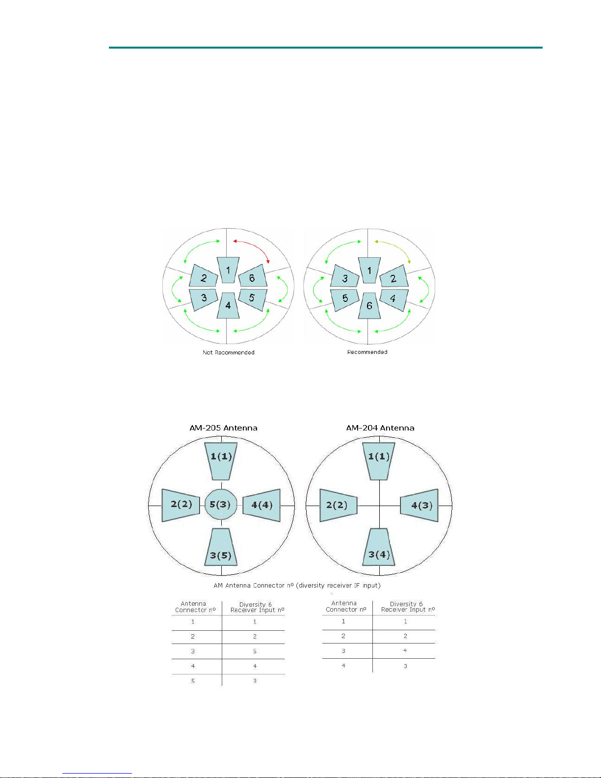
1 Installation
When several inputs are connected to the DR-106 receiver, due to input
signals processing delays, it is recommended not to have too high transition
between areas covered by the antennas connected to adjacent IF inputs of
the diversity 6 receivers.
The figure bellow shows the recommended and the less recommended
connection layout:
Figure 5.1 Not Recommended and Recommended connections
When AM-204 and AM-205 antennas are used in the receiver site,
connection should be performed as follow:
Figure 5.2 Figure 4 AM-205 and AM-204 connection to diversity 6 receivers

37
2
Contents
1 Introduction ...................................................................... 38
2 Installation ....................................................................... 38
3 Software Operation ............................................................ 39
3.1 Network Configuration ............................................................ 39
3.2 Equipment control ................................................................. 40
3.2.1 Monitor tab ..................................................................... 41
3.2.2 Data tab ......................................................................... 43
3.2.3 Logbook tab .................................................................... 44
List of figures
Figure 2.1 Front view of DR-70 ........................................................... 38
Figure 3.1 Main screen or the NetC program......................................... 39
Figure 3.2 Dialog box to add a new machine to the net .......................... 40
Figure 3.3 Monitor tab for DR-100 receiver .......................................... 41
Figure 3.4 Monitor tab for DT-70 transmitter ........................................ 42
Figure 3.5 Data tab ........................................................................... 43
Figure 3.6 Logbook Tab ..................................................................... 44
Chapter 7
NetC Software to control
remotely a network of SVP
e
q
uipment

Chapter 7: NetC Software to control remotely a network of SVP equipment
38
1 Introduction
NetC, Network Controller, is the new equipment control software developed by
SVP Broadcast Microwave. This new software lets the user control multiple SVP
machines simultaneously provided they are connected to the same local area
network.
Remote configuration and monitoring of DR-100/HDR-100 series, DR-70/HDR-70
and DT-70/HDT-70 equipment can be carried out with this new software.
Next, installation and operation of this software is described.
2 Installation
To be able to control remotely SVP machines is necessary to install the software
and then to configure the machines to make possible their communication with
the computer on which the software has been installed.
The control software application is delivered in a CD together with SVP
equipments. This software is also available on our web site:
http://www.svpbm.com/ing/support.htm
. On the web site there will always be
available the latest version of this software.
Installation of this software starts when setup file is selected. Then just follow
installation process.
To control the equipment remotely, the following steps are required:
1. The LED next to the REMOTE button must be lit in green. The REMOTE
button is used to select the remote control mode. When the LED next to
this button is lit in green, the equipment is set for remote control via the
Ethernet link, while if this LED is out, the equipment can only be controlled
locally. To activate o defuse the remote control, simply press this button.
Figure 2.1 Front view of DR-70
2. When the equipment is set for remote control (the REMOTE LED is lit in
green), the Ethernet communications parameters must be configured. Go
to Setup Configuration Menu, enter Ethernet Parameters submenu and set
the following parameters:
Chapter 7: NetC Software to control remotely a network of SVP equipment
39
a. Local IP address: this is the IP address of the SVP machine within
the LAN that it is connected to. This IP address does not have to be
fixed.
b. The IP address of the gateway or router: this is the IP address of
the router in the LAN to which the receiver is connected.
c. The subnet mask: depending on the configuration of this mask and
the remote IP address, packets transmitted by the receiver will
either be transmitted within the LAN or outside the LAN, via the
router.
d. The public IP address of the remote station to which the SVP
machine must connect. This is the IP address of the computer the
software is installed on. This IP address must be fixed.
e. The communications port to be used for communications between
the machine and the remote station. The router in the LAN to which
the remote station is connected must be configured so that packets
sent to this port are routed to the IP address configured in point d.
This completes the definition of the connection between the receiver
and the remote station. This last configuration is set in the router’s
NAT table (Network Address Translation).
3 Software Operation
Once the installation is done, we can proceed with the execution of the software.
The operation of the control software can be divided into two sections: network
configuration and equipment control.
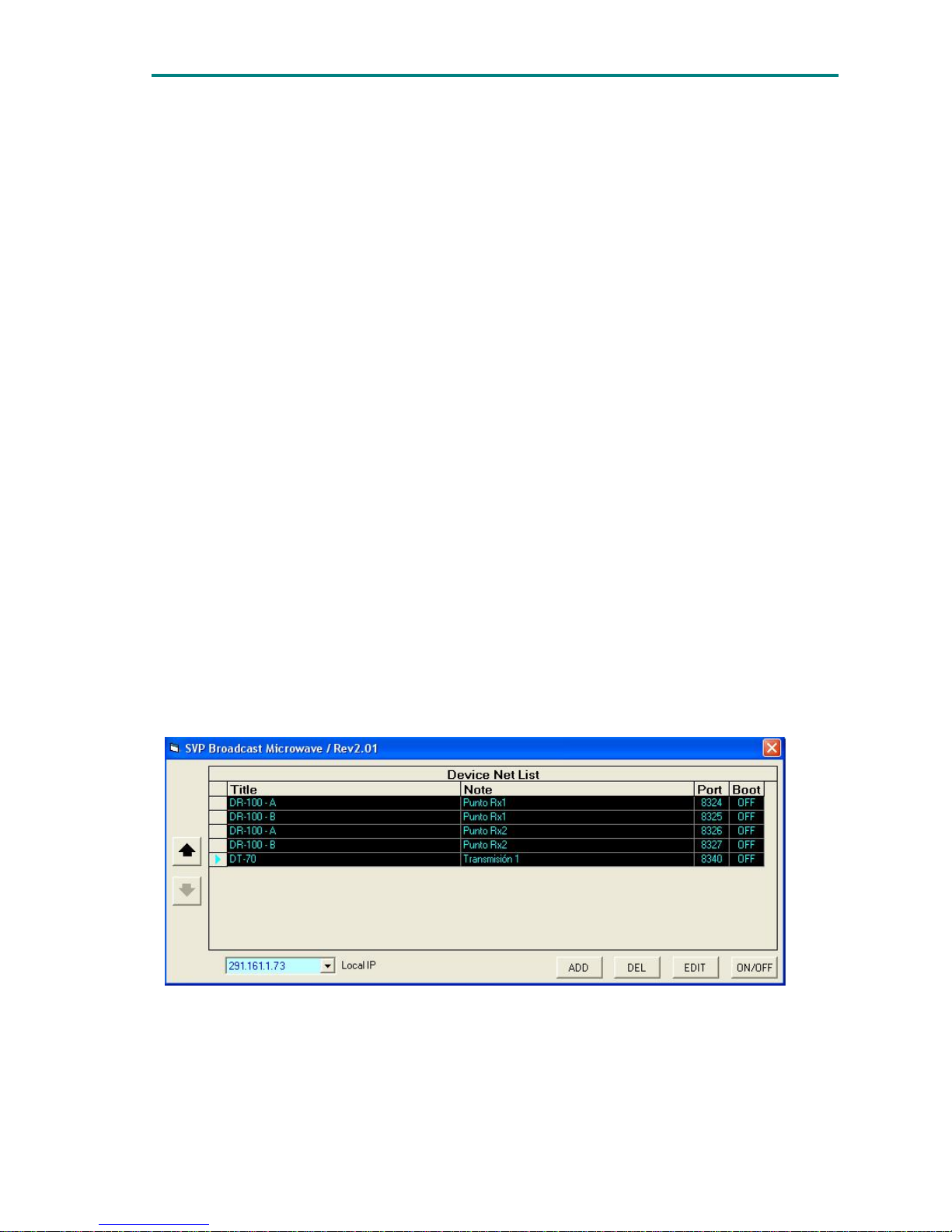
3.1 Network Configuration
When the program is run the main screen appears.
Figure 3.1 Main screen or the NetC program
Chapter 7: NetC Software to control remotely a network of SVP equipment
40
In this screen following parameters can be configured:
• Add/remove equipments to/from the network
• Edit on each equipment: name, port or notes section
• Open/close the control screen for each equipment
• Organize the list of equipments
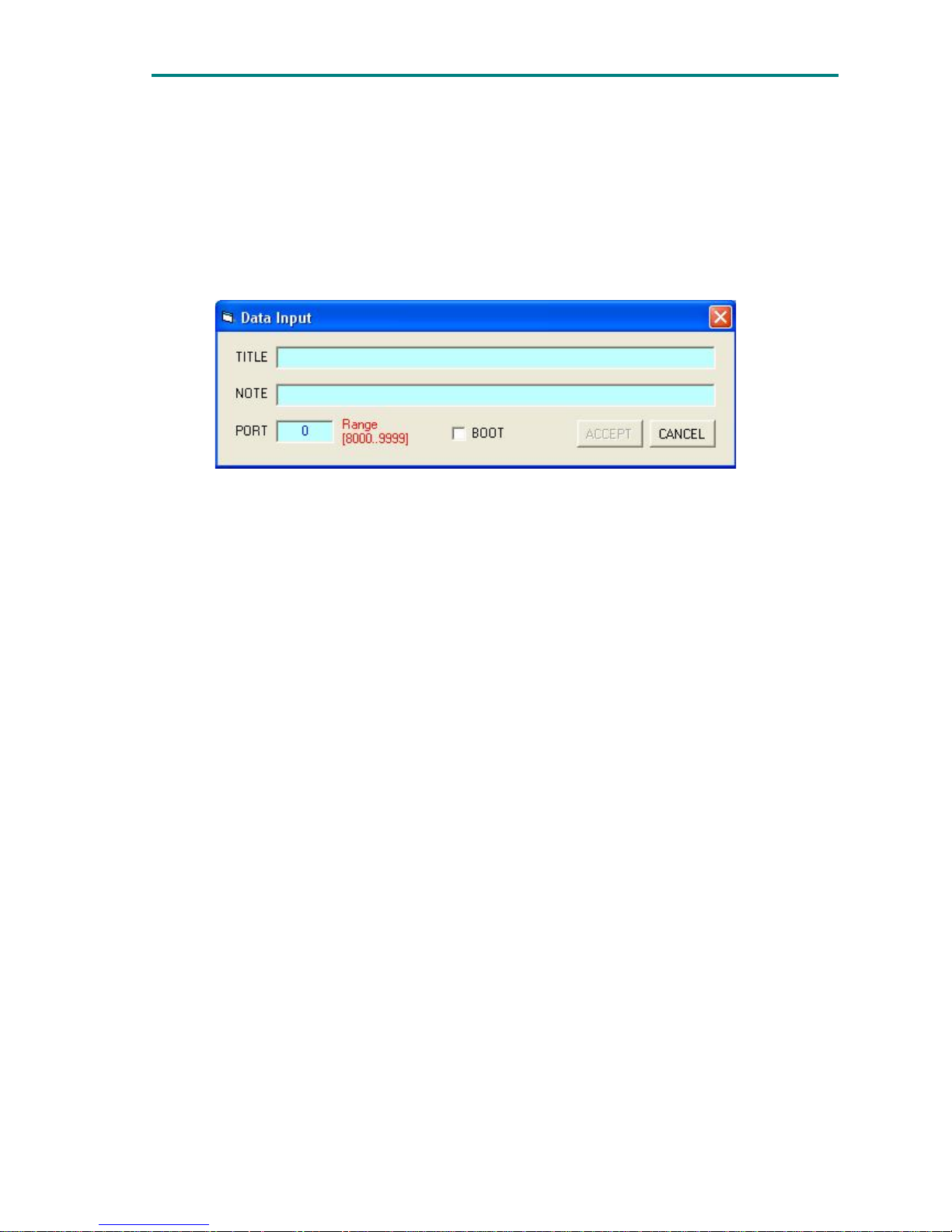
To add a new machine, ADD button must be clicked. Then following dialog box
will open:
Figure 3.2 Dialog box to add a new machine to the net
• Title: field to assign the name to the equipment that will be remotely
controlled.
• Note: paragraph to make any comment on the equipment.
• Port: communications port assigned to the machine that is to be included
in the network.
• Boot: If this field is active, the machine's control screen will open
automatically when the program is run.
To remove a machine from the network DEL button must be pressed.
Edit button opens the data input dialog box of the equipment that has been
previously selected on the main screen. Every field can be changed.
The ON/OFF button opens/closes the control window to manage equipments
remotely.
Arrows UP/DOWN are used to modify the position of the selected equipment on
the list.
3.2 Equipment control
To open the control interface of SVP equipment, first, the machine must be
selected on the main screen and then ON/OFF button must be pressed.
When the ON/OFF button is pressed a window is opened. This window has three
tabs: Monitor tab, Data tab and Logbook tab.
Chapter 7: NetC Software to control remotely a network of SVP equipment
41
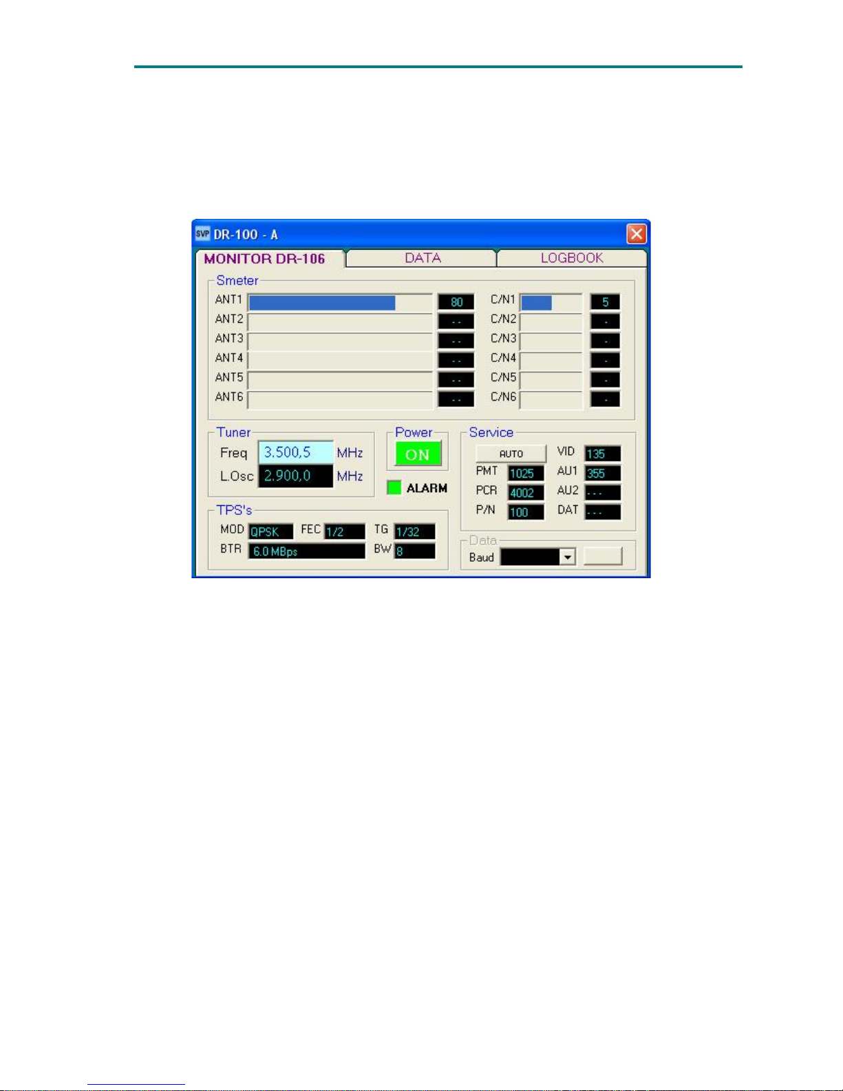
3.2.1 Monitor tab
The monitor tab allows the user to configure the most important parameters of
each machine. The content of the tab is different depending on the machine that
is connected.
Figure 3.3 Monitor tab for DR-100 receiver
For receivers the parameters displayed on the tab are the following:
• Signal Level: received signal level in each antenna. The value is
numerically and graphically displayed.
• C/N: signal to noise ratio of the signal present in each antenna. It is shown
not only numerically but also graphically.
• Reception frequency: user configurable parameter.
• Local oscillator frequency.
• Power button and shutdown.
• Information of TPS carriers (constellation, FEC code, Viterbi, and guard
interval).
• Bitrate total received in bps.
• Bandwidth in MHz
• Decoded information corresponding to the service (table PMT PID, PID for
the packets that carry the Program Clock Reference PCR, no agenda, Video
PID, Audio PID 1 PID 2 and PID audio data).
For transmitters the parameters displayed on the tab are the following:

Chapter 7: NetC Software to control remotely a network of SVP equipment
42
Figure 3.4 Monitor tab for DT-70 transmitter
The monitor tab for the transmitters, displays all data corresponding to the
transmitted COFDM signal; MPEG-2 codification, COFDM modulation,
transmission frequency and transmission power. The monitor tab is divided in the
following fields:
Input: In this field audio and video input types are configured and monitored
o Audio options: analogue or digital, embedded in SDI signal.
o Video options: composite analogue, PAL, digital SDI or DVB-ASI
Transport Stream.
When DVB-ASI input is selected the two fields on the right side are active,
one monitors the input bit rate of the ASI Transport Stream and the other
shows the packet format. There is also an overflow indicator.
Power: the On/Off button
RF field: the parameters of the up converter are monitored and some of them
can be configured. The parameters to configure the up-converter are:
o Transmission frequency
o Power supply, to feed the up-converter.
The parameters monitored are:
o Real transmitted power
o Reverse power
o Up-converter temperature
o Power supply voltage
o Up converter status (Enable/disable).
Service: In this field parameters related to video encoding, Transport Stream
and COFDM modulation are configured:
o Transport Stream: Video packets PID
Audio 1 (pair 1) PID

Chapter 7: NetC Software to control remotely a network of SVP equipment
43
Audio 2 (pair 2) PID
Program number
PMT table PID
PCR (Program Clock Reference) PID
o COFDM modulation: Constellation (QPSK, 16QAM or 64QAM)
FEC (1/2, 2/3, 3/4, 5/6 or 7/8)
Guard Interval (1/4, 1/8, 1/16 ó 1/32)
Channel bandwidth (5, 6, 7 or 8MHz)
o Video coding: MPEG-2 422 or 420
o Latency: Super low delay or Standard delay.
o Aspect ratio (4/3 ó 16/9).
o Each audio pair bitrate.
o Total transmitted bitrate.
Audio: in this field each audio pair can be enabled or disabled. Besides, each
audio level is monitored with a graphic bar and also with a numeric value. It
also points out the maximum peak value reached. This measurement is only
available when audio input signal is analogue.
3.2.2 Data tab
Provides general information about the machine connected to the local area
network: Local IP, Remote IP, port, device model, serial number, version,
temperature, etc.
Figure 3.5 Data tab

Chapter 7: NetC Software to control remotely a network of SVP equipment
44
3.2.3 Logbook tab
The logbook tab shows the last 32 warnings/alarms. However all the alarms
occurred during the day are stored in a file.
In the directory where NetC software has been installed there is a folder named
logbook. Inside logbook directory there are several folders one for each SVP
equipment on the net. The name of each folder is the text written in Title field
when the machine was added to the network. The file with the logbook
information, alarms and warnings, is stored in the corresponding folder.
Figure 3.6 Logbook Tab

Chapter 8: Remote Control via RS-232 Connection
45
Contents
1 Introduction ...................................................................... 46
2 Operation ......................................................................... 46
Chapter 8
Remote Control
via RS-232 connection

Chapter 8: Remote Control via RS-232 Connection
46
1 Introduction
The DR-100 series receivers can be controlled remotely through a RS-232
connection. A DB9 connector is located in the rear panel of the receiver.
The connection between the PC and the receiver has to be configured in order to
be able to remotely control the receiver.
2 Operation
To setup the connection, the user should configure the RS-232 connection
parameters in the Setup Configuration menu of the receiver. Steps to follow are
described below:
1.- Press ENT button to access to the main menu
2.- Using UP and DOWN arrows select Setup Configuration Menu and press ENT
button
3.- Move to line nº 10 Data options and press ENT button
In the submenu following parameters will appear:
1.- Ethernet: This option is currently locked
2.- RS-232: GPS/ Data out/ HyperTerminal
3.- Baud: 2400 – 115200bps. This parameter is locked to 4800bps when GPS
option is selected.
Once RS-232 parameter in the receiver is configured as HyperTerminal, the
receiver will allow the operator to control it remotely from a PC using the
HyperTerminal or a equivalent application. Baud rate should be the same in the
PC application and in the receiver.
The equipment is controlled remotely by a PC. RS-232 connection
Once the connection has been established between the receiver and the
computer in the HyperTerminal main window receiver’s status information will be
displayed.
-----------------------------------------“DR-120 Rev: 4.33 [ON]”
“SN: 485109902”
“Frequency: 2480,5MHz”
“BandW: 8MHz”
“TPS: 16QAM 3/4 1/16”
“PID: MANUAL”
“PMT PID: 1006”
“PCR PID: 1007”

Chapter 8: Remote Control via RS-232 Connection
47
“Vid PID: 2044”
“Au1 PID: 2048”
“Au2 PID: 2049”
------------------------------------------
There are several commands used to set or retrieve information from the
receiver. To each command the receiver will answer either with the required
information or with a message confirming that the parameter has been
configured properly.
All the commands that are sent to the receiver should end with the ‘ENTER’ key.
We will refer to it as ‘Enter’.
When the user types a single ‘Enter’ the receiver will respond:
-----------------------------------------“Command Error”
“Help + Enter for instructions”
------------------------------------------
There are several commands that must be typed before pressing ‘Enter’ key.
Each command indicates to the receiver to carry out a concrete action.
By typing ‘Help’ and pressing ‘Enter’ the receiver will display which commands
can be used and how does de operator have to type the instructions and
commands.
-----------------------------------------“Info + Enter”
“System=[on,off] + Enter”
“Frequency=xxxx,x + Enter”
“BandW=[5…8] + Enter”
“PID=[Auto, Manual] + Enter”
“[PMT, PCR, Vid, Au1,Au2]_PID=x +Enter”
------------------------------------------
These are standard commands; upon request more fields can be added.
a) INFO Command: The receiver will show the user main information
-----------------------------------------“SVP Broadcast Microwave”
“DR-120 Rev: 4.33 [ON]”
“SN: 485109902”
“Frequency: 2480,5MHz”
“BandW: 8MHz”
“TPS: 16QAM 3/4 1/16”
“PID: MANUAL”
“PMT PID: 1006”
“PCR PID: 1007”

Chapter 8: Remote Control via RS-232 Connection
48
“Vid PID: 2044”
“Au1 PID: 2048”
“Au2 PID: 2049”
“Help +Enter for instructions”
------------------------------------------
b) SYSTEM Command: This command is used to turn the equipment Off and On.
c) FREQUENCY Command: This command is used to change reception frequency.
If the frequency set is not in the receiver’s operation frequency range, it will
show an error and inform the user about the receiver’s frequency range:
“Frequency out of range [2200,0…2600,0]”
d) BANDWIDTH Command: This command is used to change the reception
bandwidth. (Options: 5, 6, 7 and 8MHz)
e) PID Command: This command is used to select PID selection mode:
Automatic or manual
Note: if there is a typing error the device will answer as shown below:
-----------------------------------------“Command Error”
“Help + Enter for instructions”
------------------------------------------

49
NOTES:

50
Final note
SVP Broadcast Microwave S.L. is constantly striving to improve all of its products.
Therefore, we ask you to understand that modifications may occur in designs,
equipment and technology. Consequently, no responsibility can be derived from
the information, illustrations or descriptions contained in this manual.
The texts, illustrations and instructions in the manual are based on the existing
situation when the manual is published.
Reprinting, reproduction and translation, in part or in whole, is forbidden
without written authorisation from SVP Broadcast Microwave S.L.
SVP Broadcast Microwave reserves all rights regarding intellectual property
rights.
All rights reserved regarding modifications

SVP Broadcast Microwave reserves the right to make changes to this manual and
to the equipment without prior notice.
SVP
Broadcast
Microwave
C/Zubiaurre 7 bajo
48215 Iurreta
Vizcaya – España
Tel: (+34) 94620 3722
Info@svpbm.com
www.svpbm.com
 Loading...