

SVP
Broadcast
Microwave
User’s Guide
CLIP ON POWER
AMPLIFIER
PAC-2G3

1
PAC-2G3 Clip-On Power Amplifier
User’s Manual
Dear customer,
We would like to thank you for choosing this equipment and welcome you to
the SVP’s products user’s growing family.
We are sure that the addition of this equipment to your existing installation
will cause you nothing but satisfaction.
Please read these instructions carefully, and keep them at hand in case you
have to refer to them.

2
PAC-2G3 Clip-On Power Amplifier
User’s Manual
IMPORTANT NOTES
1. Read the instructions carefully before connecting the power amplifier.
2. Use the amplifier together with an omnidirectional flexible antenna so
that the radiating element is elevated above the cameraman’s head.
3. In some transmitters, increasing the output power implies output signal
quality degradation due to intermodulation. Normally, at low powers a
better shoulder level is obtained. SVP Broadcast Microwave recommends
to configure the transmitters with low output power.
4. Use high quality, low loss cables and connectors to ensure proper
performance of the equipment.
5. This equipment should be used by qualified personnel only.
6. The equipment has a two-year warranty that covers any failure and
manufacturing defect, providing it is not handled by anyone other than
SVP Broadcast Microwave personnel. It should not be unsealed.
7. In our effort to constantly improve our products, we may change their
specifications without prior notice.

3
PAC-2G3 Clip-On Power Amplifier
User’s Manual
Main Index
1 Description ................................................................................. 4
2 Technical Features ..................................................................... 5
2.1 Main Characteristics ................................................................. 5
2.2 Connections ............................................................................ 5
2.2.1 Power supply ..................................................................... 6
2.2.2 RF Input ........................................................................... 7
2.2.3 RF output .......................................................................... 7
3 Amplifier Operation Tips ............................................................ 9

4
PAC-2G3 Clip-On Power Amplifier
User’s Manual
1 Description
The new PAC-2G3 is a clip-on amplifier which works in the 2GHz band. It is
used together with SVP Broadcast Microwave’s camera transmitters,
allowing the coverage of wider areas.
It can be used with neatly all camera transmitters as it can have V or AB
battery adapter plates. This small and powerful amplifier expands the
possibilities of the wireless camera transmitters. Just by adding this low
weight and compact amplifier to a camera transmitter medium range links
can be possible.
This amplifier can be 1Watt or 3 Watt output (PAC-2G3) or from 0.5 Watt to
1 Watt output (PAC-3G3), selectable from a switch in the front panel. Input
signal level has to be in the range of 10 to 100MWatt, as it has 10 dB ALC.
So the output power is not dependant on the input signal level as long as
the input signal level is in the range from 10 to 100mWatt.
This solid state LDMOS amplifier has been designed and optimized for use
with COFDM digital video signals. The low intermodulation and our
proprietary pre-distortion technique provide an excellent linearity and better
ACP performance. The predistortion technique enables higher power output
maintaining transmitted signal quality.
The amplifier can be powered through the V or AB battery adapter plates or
through a DC power supply connector, which accepts input power voltage
from 11 to 28 V.DC
The PAC-2G3 amplifier is protected against polarity reverse and over
voltage. It also has thermal protection with auto reset.
The equipment has also two Leds (Out. Level and DC), that show the
equipment’s operation state. The information provided by these two Leds is
described below:
DC Power supply Led: lights in green: The amplifier is powered.
Ouput Power Led: lights in green when the output power is set level.
The low intermodulation, the excellent RF performance and the high
reliability make this amplifier especially interesting for most demanding
wireless camera link applications.

5
PAC-2G3 Clip-On Power Amplifier
User’s Manual
2 Technical Features
2.1 Main Characteristics
Frequency range: 2,0 to 2,5 GHz
(Other frequency bands upon request)
Output Power: PAC-2G3: 1 or 3 Watt (Selectable)
PAC-3G3: 0.5 or 1 Watt (Selectable)
Input level: 10 to 100 mWatt (10 to 20 dBm)
ALC: 10 dB
Gain flatness: 0,5 dB (over full band)
Harmonics suppression: >60 dB
Output IP3: +58 dBm
Monitoring: 2 Leds in the front panel
Power supply: 11 to 28 V.DC
Consumption: 3 Watt: 2,9A @ 12V
1,4A @ 24V
1 Watt: 2,0A @ 12V
1,0A @ 24V
DC power supply connector: 4 pin Lemo 1B
Battery adapter AB or V
Protections: Polarity Reverse
Reverse power (by a circulator)
RF Connectors: 2 x N female
Mechanical dimensions: 180 x 105 x 33 mm (without connectors)
Weight: 0,97 Kg
2.2 Connections
Every connection of the PAG-2G3 Clip-on amplifier is shown in the figure
below.
Figure 2.1 PAC-2G3 Connections

6
PAC-2G3 Clip-On Power Amplifier
User’s Manual
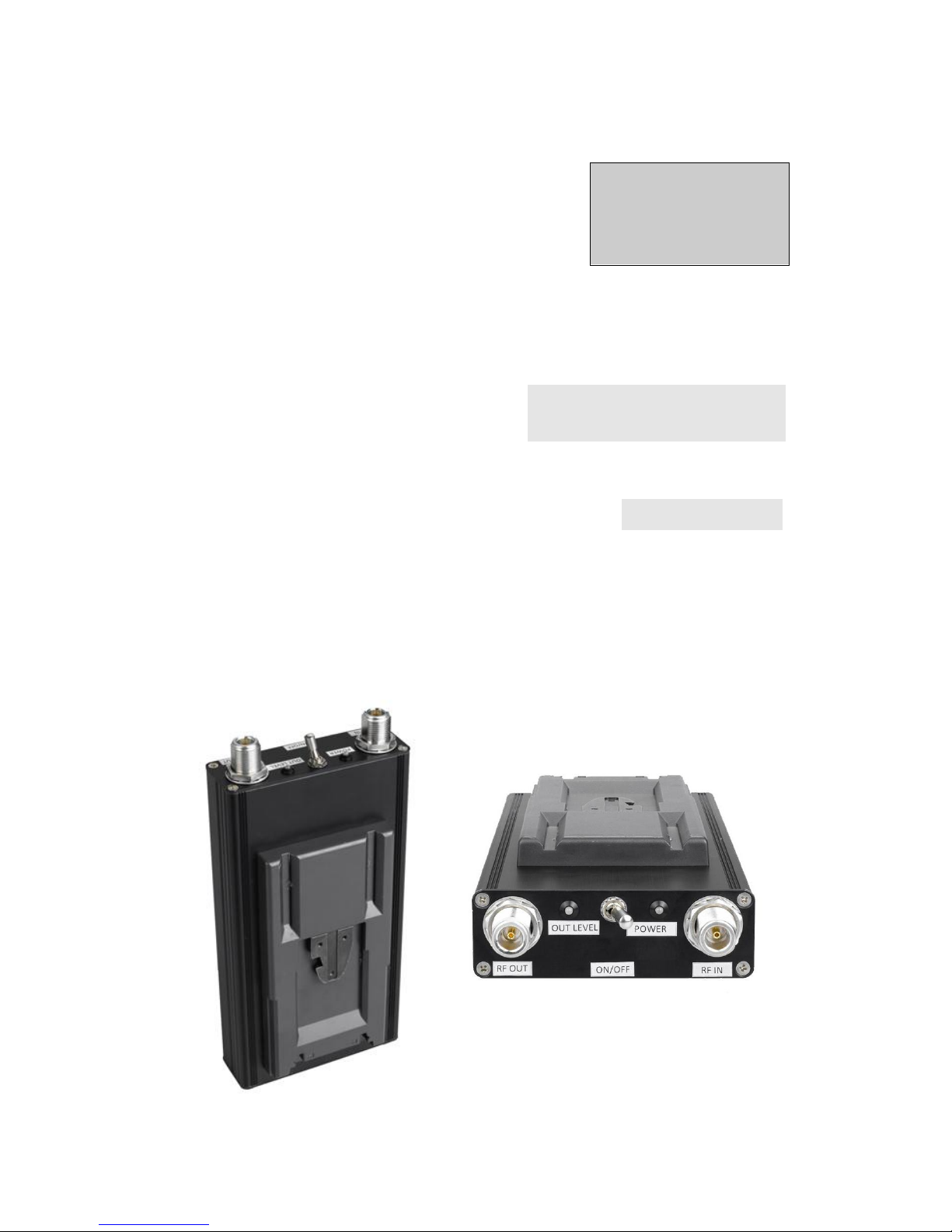
The following figures show the PAC-2G3 front and rear panels.
Connections mentioned in the upper figure are shown below.
Figure 2.2 Front panel of the PAC-2G3 Amplifier
Figure 2.3 Rear panel of the PAC-2G3 Amplifier
Technical features of each connection are described in the following
sections.
2.2.1 Power supply
The equipment can be powered by a DC source from 11 to 28 V or through
the V or AB battery clamps.
The DC power supply is connected to the equipment via a 4 pin Lemo 1B
connector.

7
PAC-2G3 Clip-On Power Amplifier
User’s Manual
Table 2.1 Power supply connection technical features
Item
Features
Connector label
POWER D.C.
Connector type
4 pin Lemo 1B
Input voltage range
11-28 V.
Consumption
3 Watt: 2,9A @ 12V
1,4A @ 24V
1 Watt: 2,0A @ 12V
1,0A @ 24V
The pin-out of the power supply connector is:
1 and 2 pins => ground
3 and 4 pins => from 11 to 28 V
2.2.2 RF Input
The RF output of the HDT-02 camera transmitter is connected to the RF
input of the PAC-2G3 amplifier. A very low loss cable should be used to
make this connection.
Table 2.2 RF input connection technical features
Item
Features
Connector label
RF IN
Frequency range
2,0 to 2,5 GHz
(Other frequency bands upon
request)
Input Level
10 to 100 mWatt (10 to 20 dBm)
Connector type
N female
Impedance
50Ω
Note: In some transmitters, increasing the output power implies output
signal quality degradation due to intermodulation. Normally, at low powers
a better shoulder level is obtained. SVP Broadcast Microwave recommends
using the transmitters configured with lowest output power.
2.2.3 RF output
The antenna is directly connected to the RF output of the amplifier.
The amplifier has la Led in the front panel which indicates the RF power
output. The RF output is protected against polarity reverse by a circulator.

8
PAC-2G3 Clip-On Power Amplifier
User’s Manual
Table 2.3 RF output characteristics
Item
Features
Connector label
RF OUT
Output frequency range
2,0 to 2,5 GHz
(Other frequency bands upon
request)
Connector type
N female
Impedance
50Ω
Output power
PAC-2G3: 1 or 3 Watt
PAC-3G3: 0.5 or 1 Watt

9
PAC-2G3 Clip-On Power Amplifier
User’s Manual
3 Amplifier Operation Tips
This third chapter provides the user with all necessary information to
operate the equipment properly.
1. If the amplifier will be powered by a battery, make sure that you have
the right battery for the equipment to operate.
2. If the amplifier will be powered through the DC IN connector. Check the
continuous voltage range and use the appropriate cable. The range of
the continuous voltage is the following one: 11 to 28 V.
3. When powering the equipment using the DC connector, be particularly
careful of the continuous power’s polarity. The power amplifier is
protected against reverse polarity.
4. Configure the output power of the transmitter. Set the output power in
Low mode.
5. Before you connect the amplifier, check that the antenna, cables and
connectors are in perfect condition. Do not switch on the device if the
antenna is not connected.
6. For the use of this amplifier together with wireless camera transmitter it
is recommended that flexible long antennas are used, for example: AVF203LB this way the radiation element of the antenna is over the
cameraman’s head.

10
PAC-2G3 Clip-On Power Amplifier
User’s Manual
Notes:

11
PAC-2G3 Clip-On Power Amplifier
User’s Manual
Final note
SVP Broadcast Microwave S.L. is constantly striving to improve all of its
products.
Therefore, we ask you to understand that modifications may occur in
designs, equipment and technology. Consequently, no responsibility can be
derived from the information, illustrations or descriptions contained in this
manual.
The texts, illustrations and instructions in the manual are based on the
existing situation when the manual is published.
Reprinting, reproduction and translation, in part or in whole, is
forbidden without written authorisation from SVP Broadcast
Microwave S.L.
SVP Broadcast Microwave reserves all rights regarding intellectual property
rights.
All rights reserved regarding modifications.

SVP Broadcast Microwave reserves the right to make changes to
this manual and to the equipment without prior notice.
SVP
Broadcast
Microwave
C/ Zubiaurre 7 bajo
48215 Iurreta
Vizcaya – España
Tel: (+34) 94620 3722
info@svpbm.com
www.svpbm.com
 Loading...